Submitted:
25 April 2025
Posted:
28 April 2025
You are already at the latest version
Abstract
Railway operators often use precast concrete box girders for railway bridges. In many cases, these box girders are placed side by side without a concrete deck on top. Sometimes these box girders are post-tensioned transversely to hold the girders together. The load distribution among the girders is easy to calculate when there is no transverse post-tensioning. Once the transverse post tensioning is introduced, the load sharing among the girders becomes more challenging to quantify. The way such a bridge is modeled will significantly affect the results of the analysis, especially when the bridge is at a skew. The assumptions made regarding the post-tensioning and how it is modeled will have a significant effect on the results due to the skew effect combined with how these girders interact. American Railway Engineering and Maintenance-of-way Association – AREMA – limits the skew angle for precast concrete slab and box girder railway bridges to 15 degrees while it allows skews up to 30 degrees for precast concrete I-girders and T-girders and 60 degrees skew angles for Cast-in-place concrete slabs and girders. AREMA does not specify limits for the skew angle of steel bridge structures. These limitations are established by way of surveying railway operators regarding their inventory of bridges rather than a scientific study analyzing the effects of such skew angles on the different types of bridges. In this paper the effect of transverse post tensioning on load sharing of precast box girder bridges is investigated and discussed for square and skew bridges. The effect of the skew on the behavior of such a bridge is also discussed and investigated through a finite element model.
Keywords:
post tensioning
; box girder
; skewed bridge
1. Introduction
Precast concrete girders are a common choice for both highway and railway bridges. In many cases, precast box girders are used without a concrete deck, and the top slab of the box acts as the riding surface for highway bridges, or as a support for the ballast and ties for railway bridges. When these girders are not post-tensioned laterally, and without a deck, the loads on each girder are determined according to the guidelines presented in the relevant codes: Canadian Highway Bridge Design Code CHBDC, or Manual for Rail Engineering published by American Railway Engineering and Maintenance-of-way Association, AREMA. When transverse post-tensioning is used, the calculation of loads requires a rigorous analysis. With the introduction of post-tensioning, some load sharing between the girders is inevitable, and can result in a more efficient design of the bridge.
Railway operators and ministries of transportation often use standard bridges for many of their rail and highway bridges of small and medium spans. Precast concrete girders are often used in these standard bridges without transverse post tensioning. Once the span of the bridge exceeds a certain threshold, the bridges need to be custom designed to satisfy the requirements of the longer spans with the applied design loads. The use of standard bridges is also limited with the skew angle of the bridge. AREMA limits the skew angle of bridges made from precast concrete box girders to 15 degrees, and to 30 degrees for precast I or T girders unless a custom design is prepared and approved. In these custom bridges, transverse post-tensioning is often used to optimize the design. Especially with railway bridges, where the rails, i.e. live load location is fixed, the load distribution according to AREMA may result in the loads not being equally distributed among the girders. In this paper the load sharing that occurs between the girders due to the transverse post tensioning is investigated.
In the following sections a description of the bridge investigated is presented, followed by a description of the model used for analysis and finally the results are presented and discussed.
1. Bridge Description
A 19 m long single span simply supported bridge, carrying one track of rail will be used for this investigation. A cross section of the bridge investigated is presented in Figure 1. The bridge consists of four precast prestressed concrete box girders placed adjacent to each other. Each girder is 1.2 m wide and 1.3 m deep. The girders are post tensioned in the transverse direction at 5 locations: over the 2 abutments, and at 3 intermediate locations at quarter span. The bridge is subjected to the following loads:
- The girders’ self-weight,
- Prestressing forces
- The ballast, ties and rail, curbs and the trainman’s walkway and handrail
- Transverse post-tensioning
- Live load represented by the Cooper E-90 loading as per AREMA, Figure 2
Considering the dead loads and the prestressing forces will be equally distributed among the girders, in this investigation we will focus on the distribution of the live loads applied on the two middle girders among the four girders and the effect of the post tensioning on that distribution.
2. Bridge Model
This bridge is modeled on SAP2000 version 18.2.0 software package using a 2D grillage model consisting of four girders and 5 lines of transverse post-tensioning cables to evaluate the live load distribution among the girders and determine the reactions at each bearing. The load sharing between the girders can be evaluated from the bending moments and shear forces distribution among the girders. A screen shot of the bridge model is presented in Figure 3. The cross section presented in Figure 4 is used to define the frame elements in the model to match the girders used for this analysis. The post tensioning cables are modeled using the tendon elements within the programme, with an effective prestressing force equal to 1275 kN for each of the post-tensioning locations. This force represents the after losses force applied from 10 – 7 wire strands.
There are three major methods of shear load transfer mechanisms between adjacent post-tensioned girders (Londoño and fib): 1) friction at the interface between the girders; 2) shear key effect and 3) dowel action. For this bridge friction at the interface between the girders will act as the load transfer mechanism. To replicate the effect of the friction due to the post tensioning, the girders are connected transversely at the locations of the post tensioning using the friction isolator link element available in the software. Using this element, the shear force transfer between the girders is developed due to the compressive force from the transverse post tensioning.
The loads were applied on each girder in the model based on its share of load according to the AREMA load distribution method (Chapter 15, clause 1.3.4). Each girder was loaded with its share of dead loads. For the live loads, two approaches are commonly used in finite element analysis:
- The loads are distributed from under the tie through the ballast to the surface of the girders. This case results in about 40% of the load being carried by each of the two interior girders and about 10% of the load being carried by each of the two exterior girders.
- The loads are distributed through the girder to the centroid of the girder as the members of the grillage model represent the centroid of the girder. This case results in about 35% of the load being carried by each of the two interior girders and about 15% being carried by each of the two exterior girders.
In this paper, the first approach is used as it conforms with the method presented in AREMA. As mentioned earlier in the introduction, in this paper we will focus on the load sharing between the girders when most of the load is applied on the interior girders; for this reason, the live load will be applied on the interior girders only, and the reactions and moments for all girders obtained for that load case. Considering the length of the train and the small spacing between the axles – as shown in Figure 2, an equivalent uniform load was applied in lieu of the train of loads for simplicity.
3. Analysis
The analysis was performed using a non-linear staged approach. First the self-weight of the girders and pre-stressing were applied, and a non-linear analysis was performed. This was followed by the application of post-tensioning and running the model. Finally, the super imposed dead loads and live loads were added. At each stage a non-linear analysis was run, and the analysis of the following stage started with the initial conditions obtained from the results of analysis of the previous stage. This analysis approach was done for both square and skew bridge models with different friction coefficients applied for the friction link isolator connecting the girders.
4. Analysis Results
In this section the results of the analysis are presented. First we will present the reactions for each girder using different friction coefficients for the friction isolator link element for the square and skew bridge models. In the next section the maximum bending moments for inner and outer girders will be presented for the different friction coefficients for both the square and skew bridges.
4.1. Reactions
First the reactions due to the live load will be presented for the square bridge, followed by the live load reactions for the skew bridge.
The friction coefficient for the friction link isolator was varied from 0 to 0.6 and the model was run with each friction coefficient. The reactions for the square model are presented in Table 1 .
As can be seen from the table above, for a square bridge, the reactions are symmetric. Both edge girders have the same reactions, and the inside girders have the same reactions. The sharing between the girders increase with increasing the friction coefficient. The higher the friction coefficient is, the higher the load sharing among the girders, up to a threshold of friction coefficient of about 0.15. Increasing the friction coefficient beyond 0.15 doesn’t result in a difference in the sharing of loads among the girders. The reactions from the skew bridge model are presented in Table 2.
From the table above, it can be seen that the load distribution/sharing among the girders changes with varying the friction coefficient. The higher the friction coefficient, the higher the obtuse corner reaction is, and lifting/tension is noticed at the acute angle corner for higher friction coefficient values. It is worth mentioning that at a friction coefficient of about 0.15 – the value at which the reactions reached an equilibrium in the square bridge, all the reaction are in compression, with the obtuse corner having a significantly higher reaction than the acute corner.
4.2. Bending Moments
The bending moments at mid-span for the square bridge are presented in Table 3.
As can be seen from Table 3, the bending moments for the square bridge are symmetric. The two inside girders have the same maximum bending moments at the mid-span, and the load sharing between the girders increases with increasing the friction coefficient. Again, with a friction coefficient beyond 0.15, the load sharing does not change, and the girders share the loads more or less equally. The bending moments at mid-span for the skew bridge girders are presented in Table 4.
As presented for the results of the bending moments at mid span for the skew bridge, the middle 2 girders carry the entire load when the friction coefficient is equal to 0, and the load sharing increases with increasing friction coefficient values. The moments are very close for the two interior girders – initially subjected to the same loads, and the same is true for the edge girders. With friction coefficients of 0.15 the 4 girders seem to share the loads equally, however at the friction coefficient above 0.15 the exterior girders seem to be subjected to higher bending moment values than the interior girders.
Discussion
The results of analysis in the previous section presented the values of the reactions and bending moments for square and skew bridges modeled with variable friction coefficients. In this section these results will be discussed with the purpose of identifying the load distribution that occurs between the girders for each of the shear and bending moment effects.
The results for the square bridge reactions for edge and middle girders are presented in Figure 5. It can be seen from the figure that the sensitivity of the model to the friction coefficient is maximized at lower values for the friction coefficient. With zero friction, each girder is completely independent, and does not share any loads. A slight increase in the friction coefficient, results in a significant increase in the load sharing among the girders. At a friction coefficient of about 0.15, the percentage of shared loads stabilizes and the maximum load transferred from an interior girder to the adjacent exterior girder reaches its maximum of 42%. So, for a 100% loading applied equally on the two interior girders of the bridge, the four girders will share the load and each of the two exterior girders will end up carrying 21% of the load, while each of the two interior girders will carry 29% of the load. This type of load sharing represents the shear loads distribution within the girders forming the super structure.
In Figure 6 the reactions for the skew bridge are presented. As can be seen in the Figure, the girders do not share any loads when the friction coefficient is set to zero, similar to the square bridge.
However, with increasing the friction coefficient, the loads are shared among the girders. The load sharing in the case of the skew bridge is different than in the case of the square bridge. In the skew bridge, the obtuse corner reaction tends to increase with increasing the friction coefficient similar to the more rigid types of structures, like slab bridges. This behaviour is ordinary for skew slab bridges, or single box skew bridges (Dilger et al., 1988). In these cases, with a rigid deck/super structure, the load tends to travel in the shortest distance, which is along the line connecting the two obtuse corners. From Figure 6, it can be seen that with increasing the friction coefficient, the reaction at the obtuse corner increases, while the reaction at the acute corner decreases. At a friction value of about 0.15 – where the square bridge seemed to reach a state of equilibrium in load sharing, the reaction at the two girders towards the obtuse corner are higher than those on the acute corner of the bridge. Exceeding this friction value – 0.15 – the bridge seems to behave like a rigid deck bridge rather than adjacent girders, with the acute corner going in tension. This kind of behaviour is very unlikely for a bridge where there is no moment continuity along the shortest load path within the superstructure – obtuse corner to obtuse corner.
Figure 7 presents the bending moments for the square bridge. With increasing the friction coefficient, the bending moments increase in the exterior girders, and decrease in the interior girders until they reach the same values and share the loads equally, at about 0.15 friction coefficient.
The bending moments for the skew bridge are presented in Figure 8. The four girders share the load equally at a friction factor of 0.15, while at lower levels of friction values, the two middle girders are subjected to higher bending moments.
While it can be seen in the above analysis that the shear loads distribution among the girders is affected by the skew angle of the bridge, the same is not true for bending moments. The skew angle doesn’t have a big effect on the way the moments are shared between the girders as can be seen from a comparison between Figure 7 and Figure 8.
A comparison between the square and skew bridge reactions is shown in Table 5. In this table, the percentage of the reaction at each girder is presented, starting with 50% of the load on each of the interior girders.

Table 5.
Reaction percentage at each girder starting with 50% of the load on each of the middle 2 girders.
Table 5.
Reaction percentage at each girder starting with 50% of the load on each of the middle 2 girders.
| Percentage of reaction from total load at end of each girder | ||||||||
| Friction Coefficient | Square Bridge | Skew Bridge | ||||||
| Girder 1, Edge | Girder 2, Middle | Girder 3, Middle | Girder 4, Edge | Girder 1, Edge Acute Corner |
Girder 2, Middle | Girder 3, Middle | Girder 4, Edge Obtuse Corner |
|
| 0 | 0 | 50 | 50 | 0 | 0 | 50 | 50 | 0 |
| 0.05 | 10 | 40 | 40 | 10 | 2 | 41 | 46 | 10 |
| 0.075 | 15 | 35 | 35 | 15 | 3 | 37 | 45 | 15 |
| 0.08 | 16 | 34 | 34 | 16 | 3 | 36 | 44 | 16 |
| 0.1 | 20 | 30 | 30 | 20 | 4 | 33 | 43 | 21 |
| 0.15 | 24 | 26 | 26 | 24 | 4 | 26 | 40 | 30 |
| 0.25 | 21 | 29 | 29 | 21 | -11 | 29 | 38 | 44 |
| 0.35 | 21 | 29 | 29 | 21 | -20 | 28 | 38 | 55 |
| 0.4 | 21 | 29 | 29 | 21 | -24 | 27 | 37 | 60 |
| 0.5 | 21 | 29 | 29 | 21 | -27 | 25 | 33 | 68 |
| 0.6 | 21 | 29 | 29 | 21 | -27 | 29 | 22 | 76 |
Table 6.
Bending moment percentage at the mid span of each girder starting with 50% of the load on each of the middle 2 girders.
Table 6.
Bending moment percentage at the mid span of each girder starting with 50% of the load on each of the middle 2 girders.
| Percentage of bending moment at mid span for each girder | ||||||||
| Friction Coefficient | Square Bridge | Skew Bridge | ||||||
| Girder 1, Edge | Girder 2, Middle | Girder 3, Middle | Girder 4, Edge | Girder 1, Edge | Girder 2, Middle | Girder 3, Middle | Girder 4, Edge | |
| 0 | 0 | 50 | 50 | 0 | 0 | 50 | 50 | 0 |
| 0.05 | 8 | 42 | 42 | 8 | 8 | 42 | 42 | 8 |
| 0.075 | 12 | 38 | 38 | 12 | 12 | 38 | 38 | 12 |
| 0.08 | 13 | 37 | 37 | 13 | 13 | 37 | 37 | 13 |
| 0.1 | 16 | 34 | 34 | 16 | 16 | 34 | 34 | 16 |
| 0.15 | 24 | 26 | 26 | 24 | 24 | 27 | 26 | 23 |
| 0.25 | 26 | 24 | 24 | 26 | 30 | 22 | 20 | 28 |
| 0.35 | 26 | 24 | 24 | 26 | 28 | 24 | 22 | 26 |
| 0.4 | 26 | 24 | 24 | 26 | 27 | 25 | 24 | 25 |
| 0.5 | 26 | 24 | 24 | 26 | 25 | 26 | 25 | 24 |
| 0.6 | 26 | 24 | 24 | 26 | 25 | 26 | 25 | 24 |
Conclusion
The load sharing between precast box girders post tensioned transversely has been investigated, and as seen in the results and discussion presented above, the girders share the shear loads and bending moments differently. The sharing of the shear loads would be different between a square bridge and a skew bridge. In a skew bridge the reactions/shears at the obtuse corner would be higher than at the acute corner provided an adequate post tensioning force is used. On the other hand, the bending moments would be shared equally between the girders as long as an adequate level of post tensioning is supplied. It would be beneficial to further investigate the effect of different skew angles on the sharing of shear forces between the girders. Also, the proper friction coefficient to model the transverse post tensioning between the girders needs to be investigated further.
References
- International Federation for Structural Concrete (fib). 2007.
- precast concrete buildings (1st ed.). Lausanne, Switzerland.
- Londoño, O. G. 2014. Finite Element Modeling of the Load Transfer Mechanism in Adjacent Prestressed Concrete Box-Beams. Masters Thesis, Ohio University, Russ College of Engineering and Technology.
- SAP2000. 2017. Computer and Structures Inc.
- Remaily, A.E.; Tadros, M.K.; Yamane, T.; Krause, G. Transverse Design of Adjacent Precast Prestressed Concrete Box Girder Bridges. PCI Journal, 1996, 41, 96–113. [Google Scholar] [CrossRef]
- Dilger, W.H.; Ghoneim, G.A.; Tadros, G.S. Diaphrams in skew box girder bridges. Canadian Journal for Civil Engineering, 1988, 15, 869–878. [Google Scholar] [CrossRef]
- Canadian Highway Bridge Design Code, CSA S6-14.
- Handbook for Railway Engineering and Maintenance of Way, AREMA, 2016.
- Paudel, Gaurab. Hexahedral Mesh Refinement Using an Error Sizing Function . 1 June 2011, scholarsarchive.byu.edu/etd/3447.
Figure 1.
Bridge Cross Section.
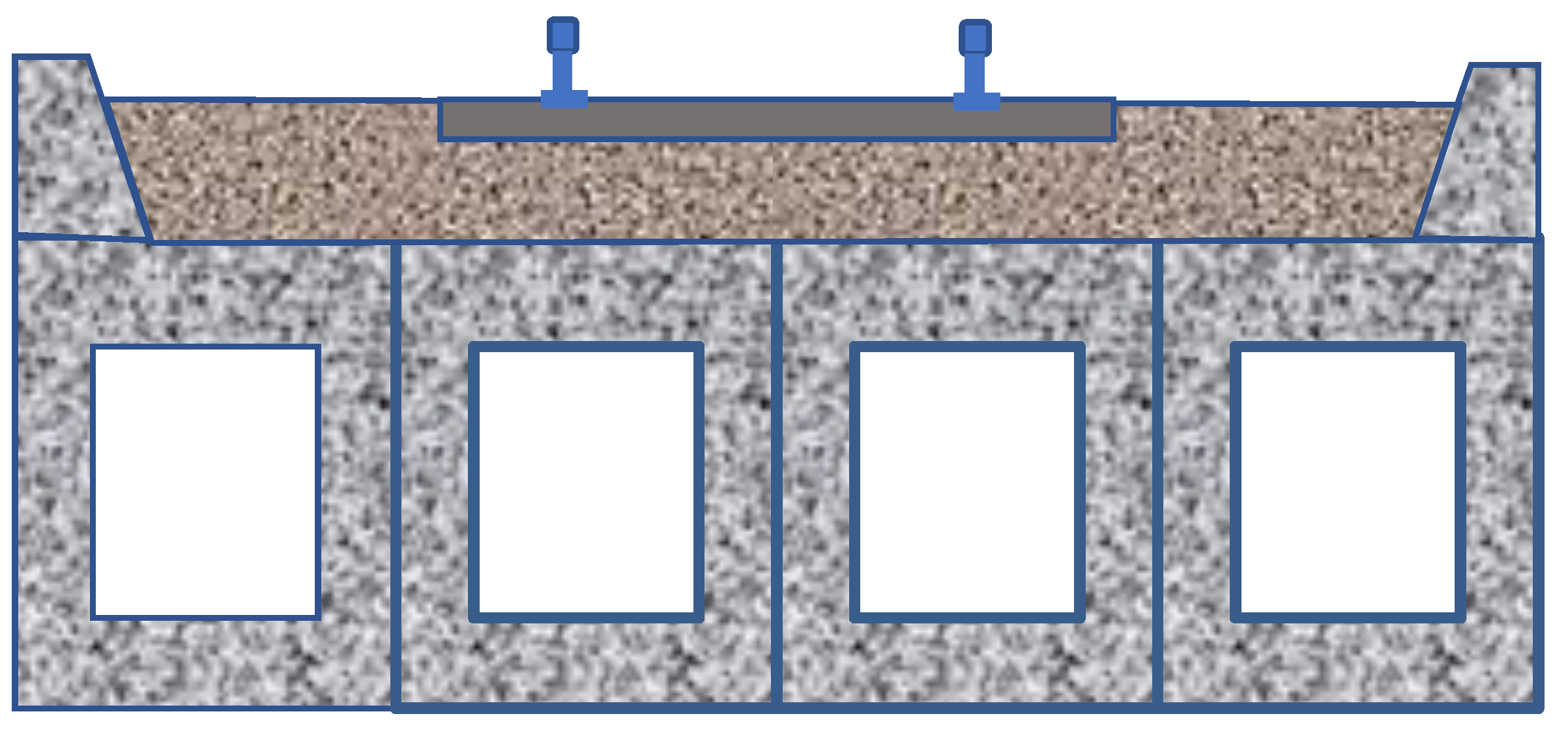
Figure 2.
Axle Loads of Cooper E-90 Loading as per AREMA.
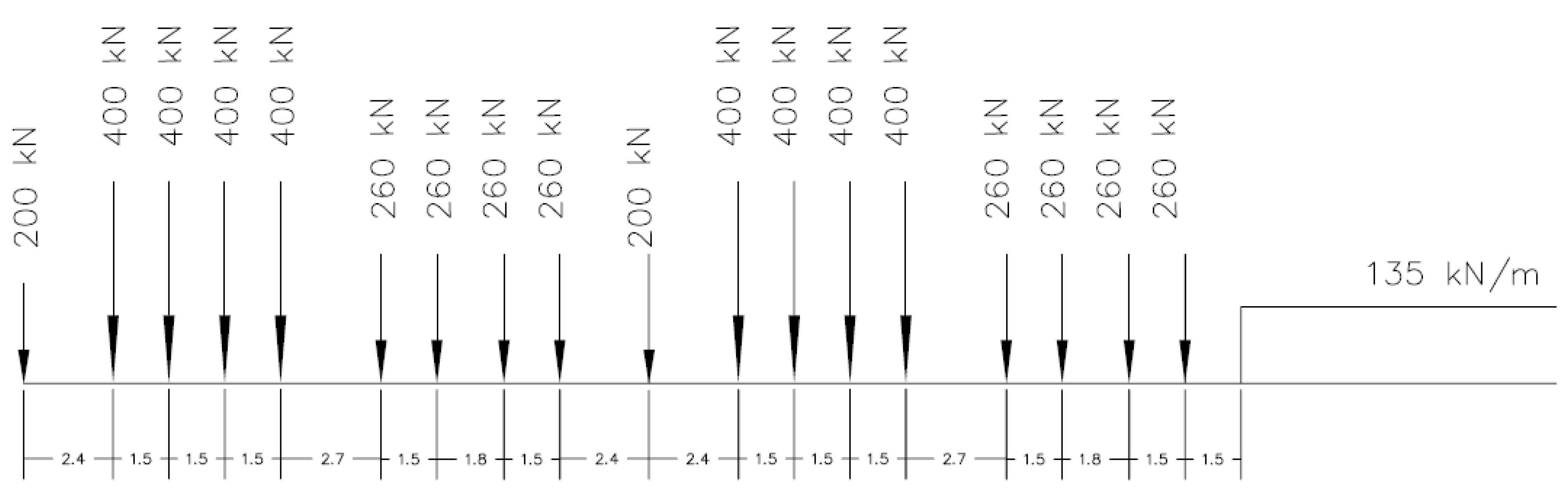
Figure 3.
View of the SAP2000 bridge model.
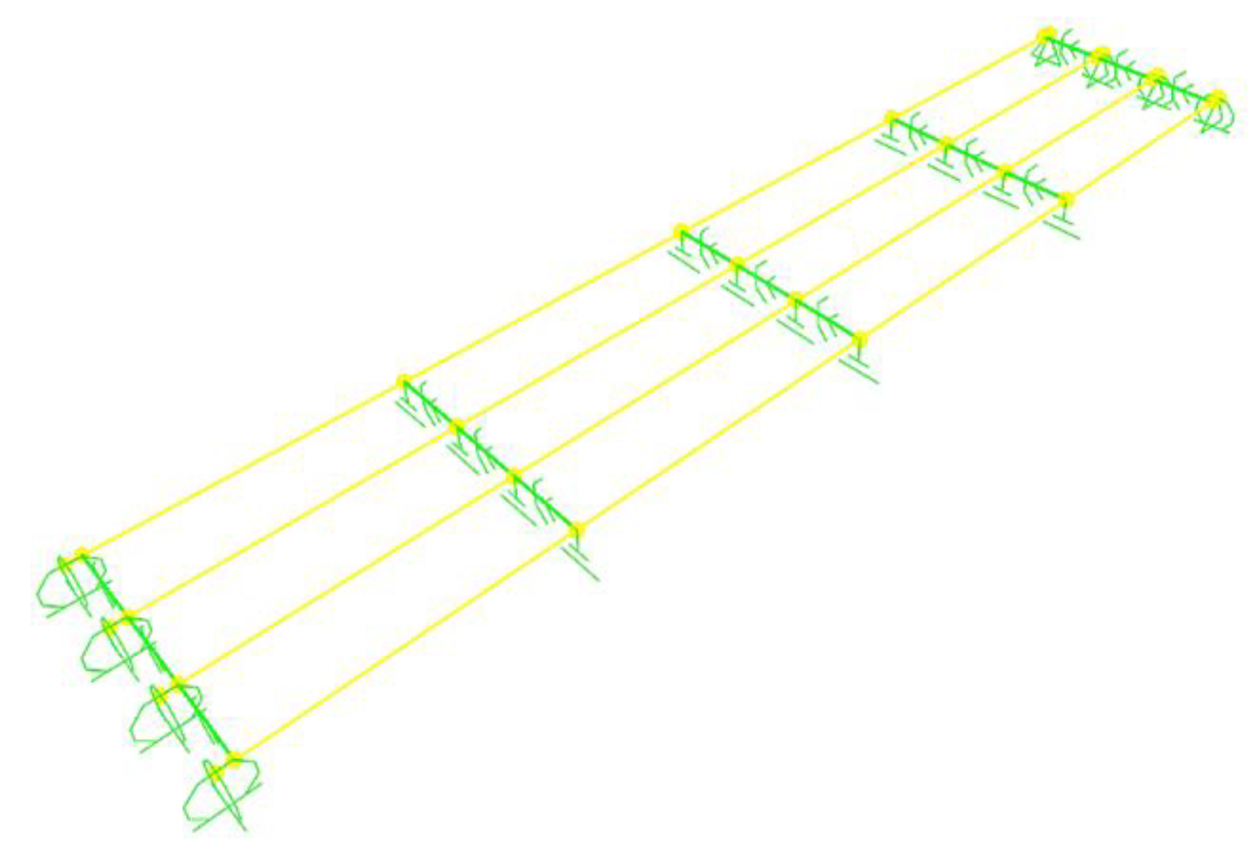
Figure 4.
Girder Cross Section.
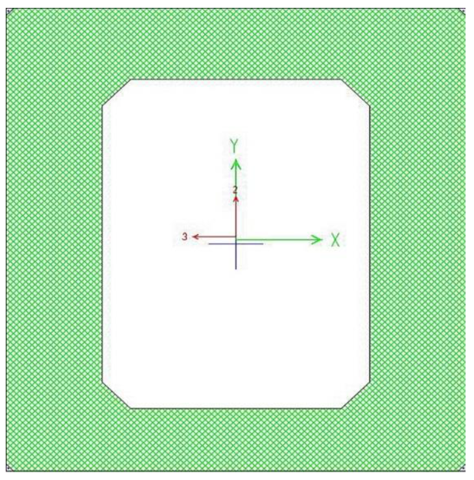
Figure 5.
Square Bridge reactions with variable friction coefficients.
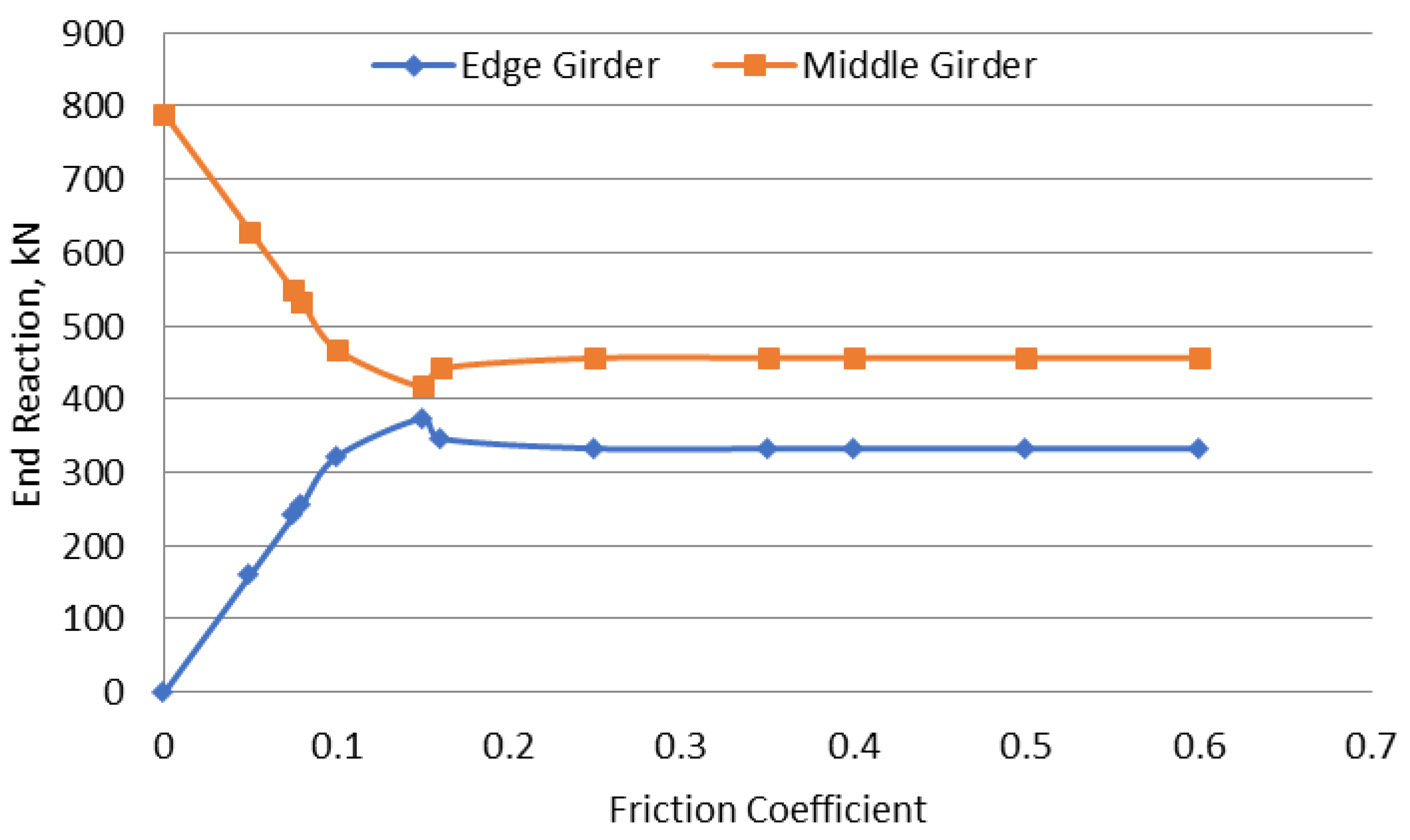
Figure 6.
Skew Bridge Reactions with variable friction coefficients.
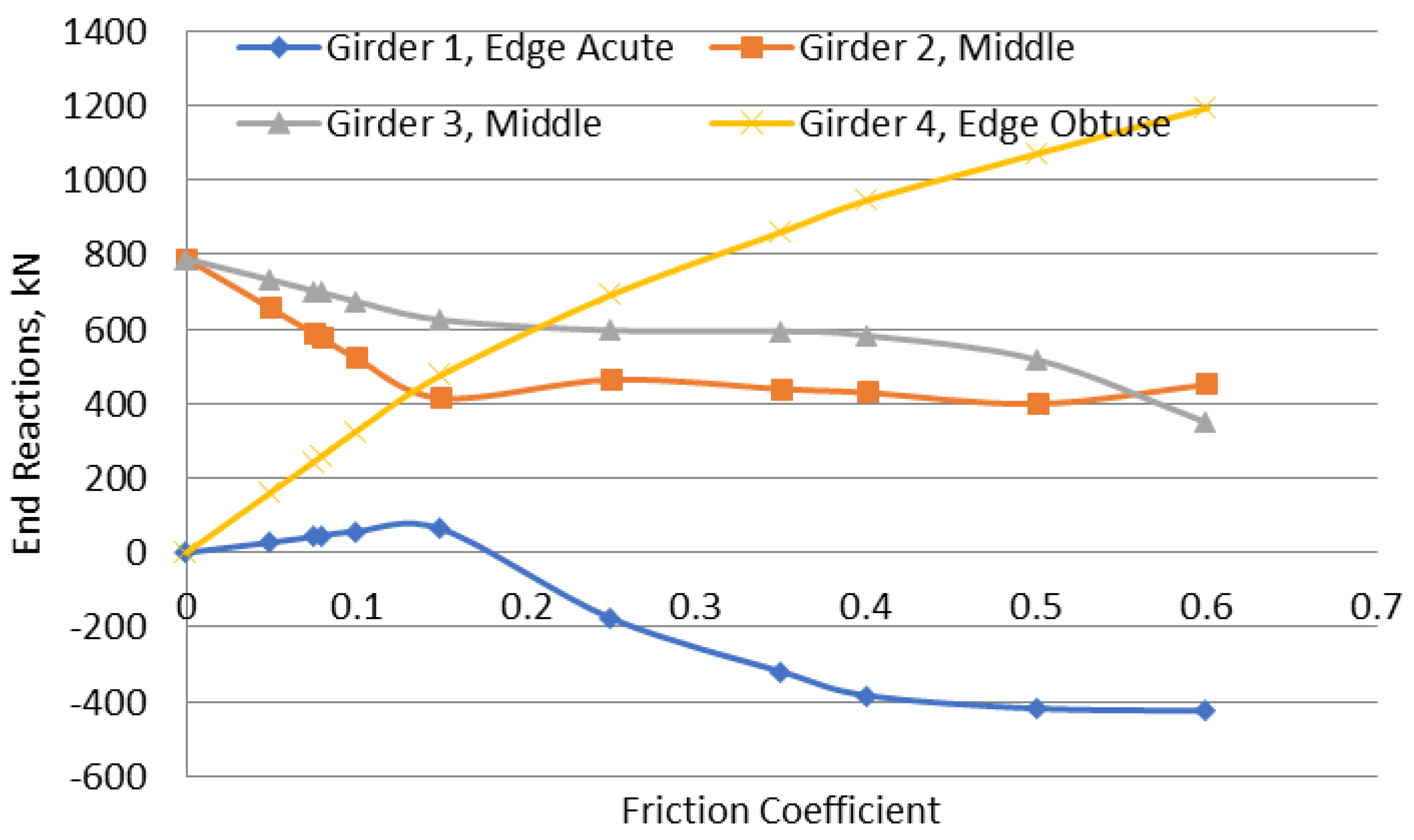
Figure 7.
Bending Moments for Square Bridge.
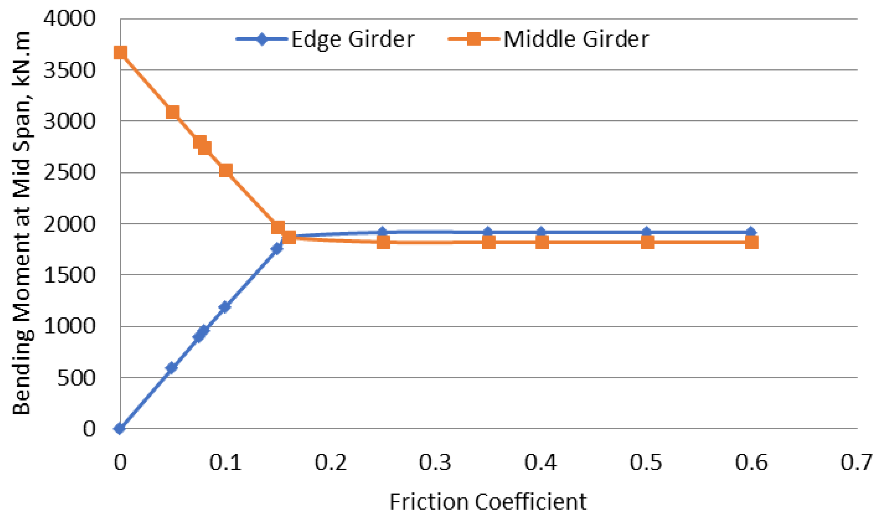
Figure 8.
Bending Moments for Skew Bridge.
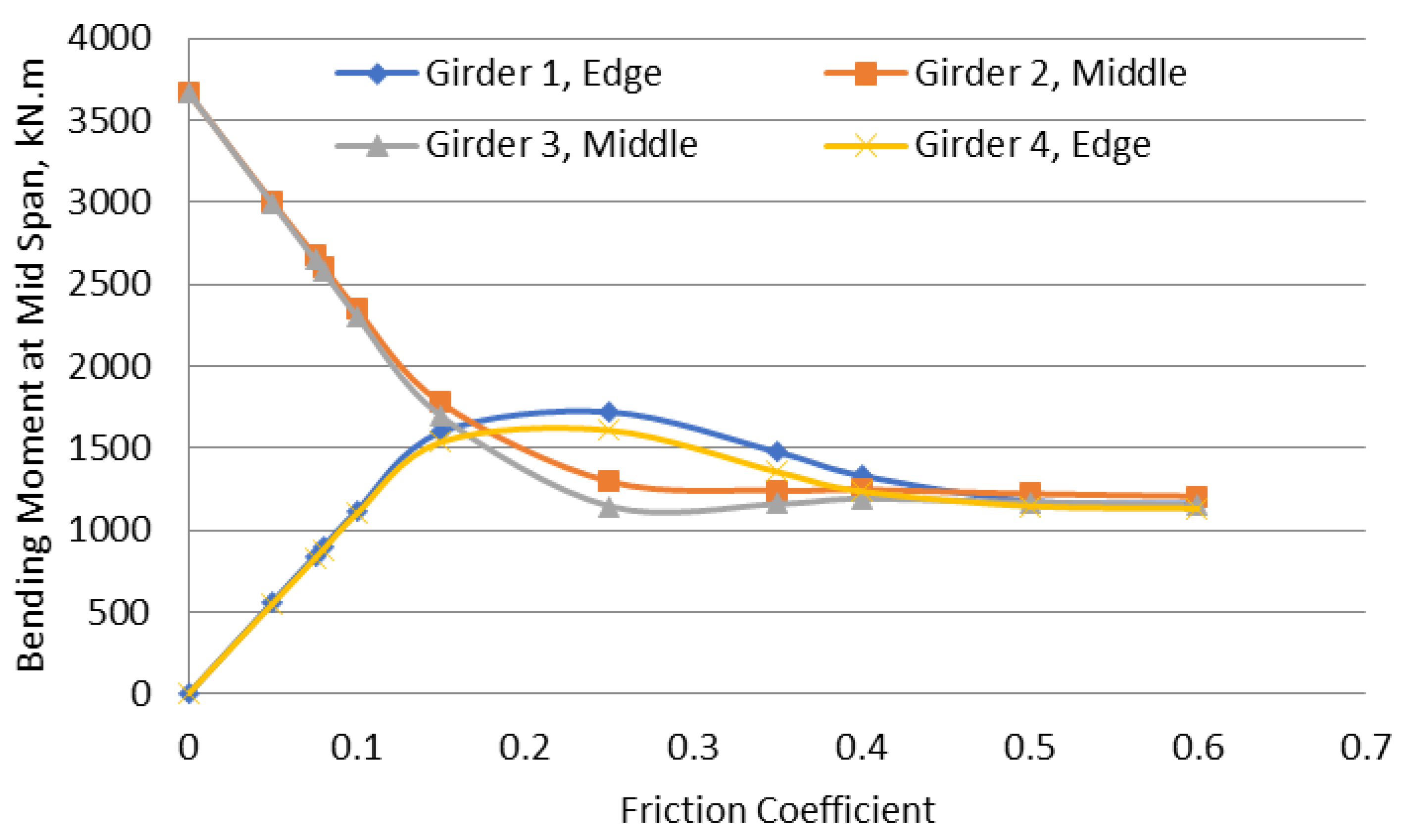
Table 1.
Reactions of square bridge for different friction coefficients.
| Friction Coefficient | Girder 1, Edge (kN) |
Girder 2, Middle (kN) |
Girder 3, Middle (kN) |
Girder 4, Edge (kN) |
| 0 | 0 | 788 | 788 | 0 |
| 0.05 | 161 | 627 | 627 | 161 |
| 0.075 | 241 | 547 | 547 | 241 |
| 0.08 | 257 | 531 | 531 | 257 |
| 0.1 | 322 | 467 | 467 | 322 |
| 0.15 | 374 | 416 | 416 | 374 |
| 0.25 | 332 | 456 | 456 | 332 |
| 0.35 | 332 | 456 | 456 | 332 |
| 0.4 | 332 | 456 | 456 | 332 |
| 0.5 | 332 | 456 | 456 | 332 |
| 0.6 | 332 | 456 | 456 | 332 |
Table 2.
Reactions of skew bridge for different friction coefficients.
| Friction Coefficient | Girder 1, Edge Acute Corner (kN) |
Girder 2, Middle (kN) |
Girder 3, Middle (kN) |
Girder 4, Edge Obtuse Corner (kN) |
| 0 | 0 | 788 | 788 | 0 |
| 0.05 | 28 | 654 | 731 | 163 |
| 0.075 | 43 | 587 | 702 | 244 |
| 0.08 | 46 | 574 | 697 | 260 |
| 0.1 | 57 | 521 | 674 | 326 |
| 0.15 | 63 | 414 | 624 | 477 |
| 0.25 | -177 | 464 | 596 | 692 |
| 0.35 | -320 | 439 | 594 | 861 |
| 0.4 | -383 | 429 | 582 | 945 |
| 0.5 | -418 | 399 | 517 | 1070 |
| 0.6 | -424 | 451 | 348 | 1193 |
Table 3.
Bending Moments at mid-span for square bridge.
| Friction Coefficient | Girder 1, Edge (kNm) |
Girder 2, Middle (kNm) |
Girder 3, Middle (kNm) |
Girder 4, Edge (kNm) |
| 0 | 0 | 3666 | 3666 | 0 |
| 0.05 | 595 | 3085 | 3085 | 595 |
| 0.075 | 895 | 2795 | 2795 | 895 |
| 0.08 | 955 | 2740 | 2740 | 955 |
| 0.1 | 1188 | 2515 | 2515 | 1188 |
| 0.15 | 1760 | 1967 | 1967 | 1760 |
| 0.25 | 1915 | 1820 | 1820 | 1915 |
| 0.35 | 1915 | 1820 | 1820 | 1915 |
| 0.4 | 1915 | 1820 | 1820 | 1915 |
| 0.5 | 1915 | 1820 | 1820 | 1915 |
| 0.6 | 1915 | 1820 | 1820 | 1915 |
Table 4.
Bending Moments at mid-span for Skew Bridge.
| Friction Coefficient | Girder 1, Edge (kNm) |
Girder 2, Middle (kNm) |
Girder 3, Middle (kNm) |
Girder 4, Edge (kNm) |
| 0 | 0 | 3666 | 3666 | 0 |
| 0.05 | 563 | 3023 | 3040 | 572 |
| 0.075 | 844 | 2720 | 2738 | 858 |
| 0.08 | 901 | 2661 | 2678 | 915 |
| 0.1 | 1117 | 2347 | 2306 | 1098 |
| 0.15 | 1597 | 1775 | 1695 | 1536 |
| 0.25 | 1720 | 1295 | 1145 | 1608 |
| 0.35 | 1475 | 1241 | 1158 | 1353 |
| 0.4 | 1894 | 1351 | 1345 | 1825 |
| 0.5 | 1955 | 1285 | 1305 | 1805 |
| 0.6 | 1930 | 1266 | 1285 | 1770 |
Disclaimer/Publisher’s Note: The statements, opinions and data contained in all publications are solely those of the individual author(s) and contributor(s) and not of MDPI and/or the editor(s). MDPI and/or the editor(s) disclaim responsibility for any injury to people or property resulting from any ideas, methods, instructions or products referred to in the content. |
© 2025 by the authors. Licensee MDPI, Basel, Switzerland. This article is an open access article distributed under the terms and conditions of the Creative Commons Attribution (CC BY) license (http://creativecommons.org/licenses/by/4.0/).
Copyright: This open access article is published under a Creative Commons CC BY 4.0 license, which permit the free download, distribution, and reuse, provided that the author and preprint are cited in any reuse.


