
Submitted:
12 August 2025
Posted:
13 August 2025
You are already at the latest version
Abstract
In the lateral joint widening projects of multi-span continuous concrete box girder bridges, significant differences in longitudinal shrinkage and creep deformation, as well as vertical deformation incompatibility between the new and old bridges, can easily lead to stress concentration within the structure, causing concrete cracking. This is particularly evident in the form of substantial overall lateral bending deformation of the structure, which affects the safety and reliability of the widened bridge. To address this common challenge, this paper proposes a novel sliding-type transverse connection structure. This structure allows the longitudinal shrinkage and creep deformation of the new bridge’s main girder to occur independently from that of the old bridge through a sliding mechanism. As a result, it effectively accommodates longitudinal deformation differences, significantly reducing both stress concentration and overall bending deformation caused by such discrepancies. To further verify its feasibility and load transfer mechanism, scaled model tests and finite element analyses were conducted. The results demonstrate that this connection structure not only effectively coordinates longitudinal deformation differences between the new and old bridges and accommodates vertical deformation between their flange plates, but also achieves efficient transverse load transfer through shear force transmission. The design of the structure is primarily governed by shear stress . These research findings indicate that the sliding-type transverse connection structure can significantly improve deformation coordination issues in bridge widening projects, ensuring good mechanical performance and safety reliability of the structure.
Keywords:
bridge widening
; sliding-type transverse connection structure
; model test
; deformation coordination
; transverse load transferring mechanism
1. Introduction
For multi-span concrete continuous box-girder bridges widened using traditional connection methods (such as wet joints or cast-in-place concrete slabs), noticeable transverse deformation often occurs at the bridge ends after several years. This is accompanied by significant shear deformation in the supports beneath the bridge ends, as well as the emergence of other related structural issues [1,2]. For example, as reported in some literature [3], for a specific continuous box-girder bridge, two years after the completion of bridge widening, significant lateral displacement occurred at the beam end, with a measured lateral offset of up to 50 mm. This led to cracking of the seismic blocks, excessive lateral shear deformation of the bridge bearings, and a loss of horizontal shear resistance capability. Additionally, longitudinal cracks were observed at the joints between the new and old sections of the bridge at the beam end.
In the widening of a continuous box-girder bridge, the longitudinal deformation caused by concrete shrinkage and creep in the new bridge is substantial, leading to a significant difference in longitudinal deformation between the new and existing bridges [3]. This difference gives rise to the following two major issues, (1) Transverse Bending Deformation Longitudinal deformation differences between the new and existing bridges can induce significant transverse bending deformation, especially at the end section of the widened structure. With increasing span length and number of spans, this transverse deformation increases rapidly, making it increasingly difficult to control. (2) Transverse Tensile Stress Concentration In addition to the difference in longitudinal deformation, there is also a disparity in foundation settlement deformation between the new and existing bridges. Under the combined influence of these two factors, the connection flange at the bridge end may experience substantial transverse tensile stress. This increases the likelihood of concrete cracking and poses a serious threat to structural safety.
Some scholars have carried out a lot of monitoring and analysis on the bridge widening of concrete girders, and the research results show that the problems mentioned above are common, the generation mechanism and prevention measures concerning the problems have also been explored. In 1998, Hosseini and Jefferson [4] studied a reinforced concrete simply supported solid slab bridge which has been widened, the results show that the longitudinal bending moment of the connection slab in the mid-span cross-section is twice the longitudinal bending moment produced by loading a 28000 kg truck here. However, no obvious transverse bending deformation was observed in this particular case. Several scholarly articles have conducted theoretical investigations and on-site monitoring of the widening of numerous long multi-span concrete continuous beam bridges[5,6,7,8] . The findings uniformly point to the significant difference by concrete shrinkage and creep between the new and existing ones, which leads to considerable transverse displacement at the end section of widened structure adopting cast-in-place concrete joints or slabs, with noticeable tensile stress detected at the connection flanges, severely impacting structural security. Researchers have proposed solutions to these problems, such as allowing the new bridge to stand for 3 to 6 months or even longer after pouring [9,10,11], but this would prolong the construction period, increase the time cost, and still be difficult to completely avoid structural defects such as lateral bending deformation after several years of connection [1,2,3].
In light of the aforementioned issues, this paper aims to investigate the control and coordination mechanism of longitudinal and transverse deformation differences between the existing and new bridges by proposing a novel sliding-type transverse connection structure. This innovative design seeks to minimize deformation differences and stress concentration, enhance the shear resistance of the structure, and improve the overall performance of the widened bridge. Furthermore, this study aims to offer a new approach and methodology for addressing structural defects in the widening of long multi-span concrete continuous box girders.
2. Segmental Model Test of Sliding-Type Transverse Connection Structure
2.1. Overview of the Test Model
To allow the new bridge to undergo free longitudinal deformation under the action of concrete shrinkage and creep, a novel sliding-type transverse connection structure (Figure 1) is proposed for the widening of long multi-span concrete continuous box girders by splicing.
The sliding-type transverse connection structure primarily consists of a square steel pipe, U-shaped steel bars, embedded steel bars, polyoxymethylene (POM) plates, and steel plates. Its operational principle is as follows:
(1) Primary structural framework: The U-shaped steel bars are embedded transversely into the existing bridge flange, and the square steel pipe is subsequently welded onto these bars to form the main structural framework.
(2) Transverse connection: A longitudinal slot is machined into the square steel pipe adjacent to the new bridge flange. The embedded steel bars are pre-installed within the new bridge flange, with stub steel bars welded to their end, and then the embedded steel bars are horizontally inserted into the slot of the square steel pipe. Then, after being rotated 90 degrees about their own axis, the stubs become vertically oriented, preventing the embedded steel bars from being pulled out of the square steel pipe slot. This ensures secure transverse connection between the new and existing bridge flanges without risk of separation.
(3) The first sliding interface: After the embedded steel bars are horizontally inserted into the slot of the square steel pipe, the interface between the embedded steel bars and the square steel pipe is meticulously polished, forming the first longitudinal sliding interface.
(4) The second sliding interface: Second sliding interface: POM plates and steel plates are placed between the new and existing bridge flanges, with the POM plates positioned against the new flange and the steel plates against the existing flange. This arrangement forms the second longitudinal sliding interface (as indicated by the red lines in Figure 1a).
Based on the widening of a three-span continuous concrete box girder bridge with variable-height cross-sections, located on the Shanghai-Nanjing Expressway in China and having a total length of approximately 140 m, this paper proposes the use of a sliding-type transverse connection structure for the widening of the aforementioned bridge. This proposal has been studied through both model testing and finite element analysis. Given that the stress state at the end segment of the widened structure is the most complex [12,13,14], this paper selects a segment of the box girder with a specific length as the research object. A segmental model of the sliding-type transverse connection structure is then designed and subjected to model testing. This paper will focus on the following aspects:
(1) In-service state of the connection structure. Under the combined effect of partial wheel loads and differential foundation settlement difference between the new and existing bridges, focus on whether the shear stress, tensile stress, as well as deflection, and other structural response indicators of the connection structure, compile with the requirements of the design code.
(2) Longitudinal sliding performance. Under the combined effect of partial wheel loads, differential foundation settlement and longitudinal deformation differences between new and existing bridges, carefully observe whether the sliding deformation and the amplitude of stress variation at the sliding interface during the sliding process, comply with the requirements of the design code, to verify the reliability of the sliding interface performance.
A portal-frame test model is developed to simulate the fixed-end constraints at the root sections of the new and existing bridge flanges. The cross-section of the model is shown in Figure 2. The longitudinal dimension of the model is 1.2 m, referring to the maximum effective distribution width of the wheel load acted on the end of the new bridge flange in the “General Specifications for Highway Bridge and Culvert Design (JTG D60-2015)” [15]. Based on the anchorage capacity of a single post-installed steel bar as specified in the Code for Design of Reinforcement of Concrete Structures (GB50367-2013) [16], the embedment lengths of U-shaped steel bars in the existing bridge flange and the embedded steel bars in the new bridge flange are determined.
2.2. Test Conditions
A sum of four test conditions have been designed in this paper to evaluate the reliability of mechanical properties and longitudinal sliding effect during the elastic working stage (as shown in Table 1).
2.3. Methods of Test Loading
During the test process, it is assumed that the existing bridge member remains fixed, and the new bridge member is longitudinally displaced by a longitudinal pushing jack, as shown in Figure 3.
Several AISI1045 steel cylinders are arranged longitudinally between the bottom formwork and bottom steel plate under the new bridge member in the test model, facilitating longitudinal sliding of the new bridge member, as shown in Figure 4a. Then, a longitudinal pushing jack applies longitudinal force to the new bridge member, inducing longitudinal displacement of the new bridge member, as shown in Figure 4b.
Two jacks are arranged at the bottom of the new bridge member, as illustrated in Figure 4. The vertical settlement deformation is controlled by the control system (PLC) within an electric oil pump, and displacement sensors are arranged for monitoring, thereby creating differential settlement difference between the new and existing bridge members. The maximum settlement displacement is set to 2.5 mm, simulating the foundation settlement deformation difference of approximately 5 mm at a scale ratio of 1:2 [2,3].
The double-point static loading method is adopted to simulate partial wheel loads, and the test model is loaded through a load-distribution beam and two loading pads, as shown in Figure 3. According to “General Code for Design of Highway Bridges and Culverts (JTG D60-2015)” [15], the test selects the rear-axle load of 140 kN as the single-axle wheel load. According to the principle of equal stress and a scale ratio of 1:2, the calculated value of loading in the jack is 70 kN, with each loading point being applied to a load of 35 kN. To test the most unfavorable stress state of the test model, the load-distribution beam is placed at the end of the model, as shown in Figure 3. Since the longitudinal deformation difference at the beam end section is the greatest after the transverse connection of the old and new bridges, it is considered that the beam end section is subjected to the most unfavorable loading condition as previously described. Based on the above reasoning, the transverse loading beam is therefore arranged at the beam end section.
2.4. Arrangement of Stress and Deflection Monitoring Instruments
The measurement points of concrete stress are only arranged on the front side of the model, as shown in Figure 5, with a 45° strain rosette attached at each measurement point. In Figure 5, F represents the single wheel load on the bridge deck, and points S1 to S12 represent the stress measurement points.
Stress measurement points for the steel bars inside the model are distributed on the surfaces. For the square steel pipe, as well as steel plates, the embedded steel bars, and other components, stress measurement points are also distributed on the surfaces. Strain gauges arranged on the structural steel bars are shown in Figure 6, and strain rosettes arranged on the surfaces of the square steel pipe and steel plates are shown in Figure 7. In Figure 6 and Figure 7, Figures S13 to S26 represent stress measurement points.
The deflection measurement points as shown in Figure 8 are arranged on the top surface of the test model, where points a and b are arranged on the surface of existing bridge flange, and points c and d are arranged on the surface of new bridge flange. Dial gauges are used to measure the deflection.
3. In-Service State of the Sliding-Type Transverse Connection Structure
Based on the test data from conditions 1 to 3, demonstrate the safety of in-service stress state of the connection structure, under the combined action of wheel loads on the bridge deck and the foundation settlement of new bridge.
The deflection distribution pattern of the deflection measurement points under each test condition are shown in Figure 9. The deflection data indicates that, the sliding-type transverse connection structure can coordinate the vertical deformation between the new and existing bridge flanges. The deflection difference at the joint indicates that the core component such as square steel pipe has undergone shear deformation, accompanied by the transverse transmission characteristics of vertical shear force.
Figure 10 shows the distribution of concrete principal tensile stress at each stress measurement point. It can be seen from the figure that the maximum concrete principal tensile stress at the root section of the flange is 2.39MPa, which is close to the standard value of tensile strength for C40 concrete, 2.40MPa. The sliding-type transverse connection structure doesn’t crack, indicating that the connection flange remains in the elastic working stage, with a sound in-service state.
Take condition 3 as an example, the stress scatter plot is shown in Figure 11. As can be seen from the figure, the stress at most measurement points on the steel bars is small. Only the stress measurement point S23 on the U-shaped steel bar at the loading cross-section, which is near the application point of single wheel load, has maximum axial tensile stress of 267.78 MPa at the top of vertical part, but this value is lower than the design value of tensile strength of HRB400.
The longitudinal stress and shear stress generated at the ends of the square steel pipe and steel plates are exceedingly small, which is not listed in detail due to space limitations. Both the square steel pipe and steel plates are in the safe in-service states.
As mentioned above, the test model is in the elastic working state, the sliding-type transverse connection structure does not crack, and the durability of the structure is guaranteed.
4. Verification Analysis of Sliding Performance
Based on condition 3, a longitudinal thrust is applied to the end section of new bridge member to generate longitudinal displacement, forming a new test condition (Condition 4). The longitudinal jacking displacement shall be controlled within 10mm to ensure the loading safety of the test structure. The comparing of deflection data at all measurement points between Conditions 3 and 4 (Figure 12) indicates that the sliding-type transverse connection structure remains in an elastic working state throughout the longitudinal sliding process. The comparison of concrete first principal stress from measurement points at the tensile zone between conditions 3 and 4 is shown in Figure 13. It can be seen from the figure that the deflection or stress state of this connection structure does not change significantly during the two conditions, and the transverse distribution law of settlement deformation difference in the connection flange does not change either. This indicates that the longitudinal deformation difference does not affect the transverse connection function of the structure.
In conclusion, the sliding-type transverse connection structure can effectively absorb the longitudinal deformation difference by concrete shrinkage and creep between the new and existing bridges, thereby avoiding the adverse mechanical effects resulting from the difference by concrete shrinkage and creep between the new and existing ones in the widened structure, which has good application prospects for the bridge connection widening.
5. Analysis of the Transverse Load Transferring Mechanism
To research the transverse load transferring mechanism of the sliding-type transverse connection structure, a finite element model of the segmental test model is established and analyzed by adopting the Diana FEA finite element analysis software.
5.1. Material Properties and Constitutive Relationship
According to the “Design Code for Highway Reinforced Concrete and Prestressed Concrete Bridges and Culverts (JTG 3362-2018)” [17], the material properties are shown in Table 2.
In the finite element model, the Von Mises plasticity model is selected as the constitutive relationship of the reinforcement and AISI1045 steel. The constitutive relationship of concrete in the tensile state adopts the exponential model (as shown in Figure 14a); The constitutive relationship of concrete in the compressive state adopts the parabolic model (as shown in Figure 14b). In the figure, is the I-type (open-type) tensile fracture energy, and its calculation formula refers to relevant literature [18,19]; is the nonlinear compressive fracture energy, and its value is taken according to relevant literature [20,21], is the standard value of tensile strength; is the standard value of compressive strength; h is the thickness index. According to the literature[22,23] , the yield tensile strength of the copolymerized formaldehyde material, POM M90, can be taken as 60 MPa, and the tensile modulus of elasticity can be taken as 2760 MPa; the flexural strength is 61 MPa, and the flexural modulus is 2400 MPa. The bond-slip constitutive relationship of anchored rebars in the concrete is set according to the relevant provisions in the “Code for Design of Concrete Structures (2015 Edition) (GB 50010-2010)” [24].And the allowable stress of the welds between U-shaped steel bars and the square steel pipe is 49.5MPa.
The connection structure mainly adopts hexahedral solid elements HX24L, while a small number of tetrahedral solid elements TE12L and triangular prism solid elements TP18L are adopted for the concrete, steel plates, polyformaldehyde plates, etc., which are at the end of the flanges near the joint. The concrete element mesh size is set to 25 mm. The thickness of the polyformaldehyde plates and steel plates at the connection structure is relatively small, and the corresponding element mesh sizes are set to 5 mm and 6 mm respectively. Rebar-type elements are adopted for the steel bars inside the concrete, with the element mesh size of 50 mm. Beam-type elements L13BE are adopted for U-shaped steel bars and embedded steel bars, both with the element mesh size of 25 mm.
In the finite element model of Diana FEA[25], discrete interface elements are adopted to simulate the interface performance between U-shaped steel bars and the square steel pipe; Bond-slip interface elements are adopted to simulate the interface performance between U-shaped steel bars or embedded steel bars and the concrete; Nonlinear friction interface elements are adopted to simulate the characteristics of POM-steel interface. The finite element model contains 154392 elements.
Figure 15 shows the finite element model and the simulated boundary conditions, in which the consolidated walls of the flanges are omitted. The X-axis in the coordinate system is the longitudinal bridge direction of the test model, and the longitudinal push direction is the positive direction; The Y-axis is the transverse bridge direction, and the new bridge member is in the positive Y-axis direction; The Z-axis is the vertical bridge direction, and upward is the positive direction. The boundary conditions of sliding-type transverse connection structure can be simulated as a fixed constraint set at the root section of the existing bridge flange, restricting all degrees of freedom; For the new bridge flange, a translational constraint is set at its root section, restricting its translational degree of freedom in the transverse direction (Y-axis) and all rotational degrees of freedom.
Under the same test conditions, select key deflection measurement points, and then compare test results with finite element analysis results, to verify the accuracy of the finite element model in simulating actual deformation for sliding-type transverse connection structure.
5.2. Elastic Working State
This section focuses on analyzing the working mechanism of the sliding-type transverse connection structure under the action of partial wheel loads, when the internal force is transferred from the new bridge flange to the existing bridge flange. This study aims to investigate the vertical deformation behavior of the connection structure and the stress distribution within key components.
The partial wheel loads are consistent with ones in the model test. Under the action of partial wheel loads, vertical deformation diagrams of the new and existing bridge flanges at the loading cross-section, as well as the square steel pipe, U-shaped steel bars and embedded steel bars are shown in Figure 16. As shown in Figure 16, the wheel loads on the bridge deck applied on the new bridge flange, causing its end to deflect downward. The deflection of the new bridge flange also causes the square steel pipe to deflect downward. Subsequently, the vertical parts of U-shaped steel bars welded to the square steel pipe also undergo vertical displacement, causing the existing bridge flange to deflect downward ultimately. This realizes transverse load transmission and deformation coordination between the new and existing bridge flanges. The vertical deformation curves of the two flanges have different curvatures at the connection structure, indicating that the deformation coordination between the new and existing bridge flanges is achieved by transferring shear force rather than bending moment.
To clearly illustrate the transverse load transmission mechanism, the principal stress trajectory lines of each component in the sliding-type transverse connection structure are analyzed. The principal stress trajectory lines at the ends of the new and existing bridge flanges, as well as the square steel pipe, the U-shaped steel bar and embedded steel bar at the cross-section of wheel loads application are shown in Figure 17. In the figure, S is the principal stress, the warm-colored lines represent the principal tensile stress, and in contrast, the cool-colored lines represent the principal compressive stress. The longer the line, the larger the principal stress at the location, and the extension direction of the line is the direction of the principal stress.
From the principal stress trajectory lines, it can be known that the transverse load transferring mechanism of sliding-type transverse connection structure under the partial wheel loads is as follows: Single wheel load causes the concrete above the groove of the new bridge flange to experience shear stress and deform downward to squeeze the square steel pipe, resulting in significant principal compressive stress in the concrete above the groove (as shown in Figure 17a,b); The concrete above the groove of the new bridge flange transmits pressure to the upper surface of the square steel pipe, causing the upper limb of the square steel pipe to bend transversely, at the same time, the vertical part of the square steel pipe experiences significant vertical shear force, resulting in large principal compressive stress in it (as shown in Figure 17c); As the vertical part of the square steel pipe experiences significant downward shear stress, the vertical part of the U-shaped steel bar at the loading cross-section primarily experiences vertical principal stress, and the axial tensile stress decreases gradually from top to bottom until the lower part enters compressive state (as shown in Figure 17d); There is almost no transverse principal stress in the horizontal part of the U-shaped steel bar, indicating that, after transverse load is transferred to the vertical parts of U-shaped steel bars, the load continues to be transferred to the interior of existing bridge flange by the form of shear force.
According to the above analysis, it can be known that the path of transverse load transmission from the new bridge flange to existing bridge flange is as follows: The single wheel load acted on the end of new bridge flange causes the new bridge flange to deflect downward, and the downward deformation of the square steel pipe is caused by the squeezing of the concrete above the groove of new bridge flange and the upper limb of the square steel pipe; Then, through the welding relationship between the vertical parts of the square steel pipe and U-shaped steel bars, the vertical parts of U-shaped steel bars experience vertical displacement, resulting in the deflection of the existing bridge flange. This achieves transverse load transferring and deformation coordination between the new and existing bridge flanges.
Figure 17 (d) also shows that the embedded steel bars experience transverse principal stress at only one end close to the root section of the flange, which is related to the fixed constraint there. This indicates that embedded steel bars do not participate in the transverse load transmission, which only serve the function of connecting components to limit the width of the connection joint, avoiding separation of new and existing bridge flanges from each other.
The transverse load transferring mechanism in the elastic working stage shows that the transverse stress state of sliding-type transverse connection structure is mainly controlled by shear stress, and the transverse load transmission is realized by transferring shear force. The squeeze deformation between the concrete above the groove and the upper limb of the square steel pipe is closely related to as follows: the shear resistance of the concrete above the groove, as well as the thickness of the square steel pipe, and the welding strength between the vertical part of the square steel pipe and vertical parts of U-shaped steel bars.
6. Conclusions
(1) When the novel sliding-type transverse connection structure is employed for the widening of long multi-span concrete continuous box girder bridges, the new bridge is capable of effectively accommodating longitudinal deformations caused by concrete shrinkage and creep. This capability holds even under the combined effects of wheel loads on the bridge deck and differential foundation settlement. Overall, the widened bridge can effectively accommodate the longitudinal deformation difference between the new and existing bridge segments, thereby significantly reducing structural incompatibility and stress concentration at the connection interface.
(2) This paper proposes a testing method that simultaneously imposes wheel loads on the bridge deck, differential foundation settlement, and longitudinal deformation differences between the new and existing bridge segments onto the transverse connection structure. This approach effectively simulates actual engineering conditions, producing more realistic structural responses and enhancing the overall quality of the research.
(3) The transverse stress state of the sliding-type transverse connection structure is predominantly governed by shear stress, with the structure primarily relying on the transfer of shear forces to achieve effective transverse load transmission. The squeeze deformation at the interface between the upper limb of the square steel pipe and the overlying concrete, together with the shear action between the vertical segments of the square steel pipe and the U-shaped steel bars, constitute the two primary mechanisms for transverse load transfer between the new and existing bridge flanges. In addition, the transverse flexural stiffness of the square steel pipe and the shear resistance of the welds connecting it to the U-shaped steel bars contribute to enhanced transverse connection stiffness of the structural system. To ensure effective transverse load transmission between the new and existing bridge flanges, all these factors are critical and require careful consideration during the design phase.
This study focused on the experimental investigation of the serviceability performance of the new connection structure. Further research is required to investigate the failure modes, load-carrying capacity, and the key factors influencing structural behavior observed in the model tests. Moreover, optimization studies on the cross-sectional form of the sliding-type connection structure are necessary, aiming not only to satisfy the requirements under normal service conditions but also to improve the overall structural performance.
Supplementary Materials
The following supporting information can be downloaded at website of this paper posted on Preprints.org.
Acknowledgments
The authors are grateful for the funding support of the National Natural Science Foundation of China (52278149).
References
- Wen, Q.J. Long-term effect analysis of prestressed concrete box-girder bridge widening. Construction and Building Materials 2011, 25, 1580–1586. [Google Scholar] [CrossRef]
- Shi, X.; Li, X.; Ruan, X.; et al. Analysis of structural behavior in widened concrete box girder bridges. Structural Engineering International 2008, 18, 351–355. [Google Scholar] [CrossRef]
- Wu, W.; Tang, Z.; Zhang, H.; et al. Research on structural diseases due to a joint widening of concrete continuous box girder bridge. China Journal of Highway and Transport 2018, 31, 63–73. [Google Scholar] [CrossRef]
- Hosseini, M.; Jefferson, A.D. Time-dependent behavior of widened reinforced concrete under-bridge. Materials and Structures 1998, 31, 714–719. [Google Scholar] [CrossRef]
- Chen, K.M.; Wu, Q.X.; Chen, B.C.; et al. Research on connection of long pre-stressed concrete continuous beam bridge. Journal of Guangxi University (Natural Science Edition) 2016, 41, 1238–1245. [Google Scholar] [CrossRef]
- Fang, Z.; Chang, H.H.; Yang, X.Q.; Yuan, Y. Lateral Effects Caused by Shrinkage and Creep in Widened and Spliced Concrete Box Girder Bridges. China J. Highw. Transp. 2013, 26, 65–72. [Google Scholar] [CrossRef]
- Wu, W.; Zhang, H. Analysis of structural diseases in widened structure due to the shrinkage and creep difference of new bridge. AIP Conference Proceedings 2018, 1944, 020001. [Google Scholar] [CrossRef]
- Tu, B.; Fang, Z.; Dong, Y.; Frangopol, D.M. Time-Variant Reliability Analysis of Widened Deteriorating Prestressed Concrete Bridges Considering Shrinkage and Creep. Eng. Struct. 2017, 153, 1–16. [Google Scholar] [CrossRef]
- Wu, W.; Zhang, H.; Liu, Z.; et al. Numerical Analysis on Transverse Connection Structure for the Widening of a Long Multi-Span Highway Concrete Continuous Box Girder Bridge. Materials 2022, 15, 6805. [Google Scholar] [CrossRef]
- American Concrete Institute. Guide for widening highway bridges: ACI 345.2R-13[S]. Farmington Hill, MI, USA: American Concrete Institute, 2013.
- Chai, Y.H.; Hung, H.J. Waiting period for closure pours in bridge widening or staged construction. Journal of Bridge Engineering 2016, 21, 4016006. [Google Scholar] [CrossRef]
- Wu, W.; Cao, C.; Wu, Y.; et al. Numerical Analysis on Sliding-Type Transverse Connection Structure Applied in Widening Continuous Concrete Box-Girder Bridge. Buildings 2025, 15, 35. [Google Scholar] [CrossRef]
- Jefferson, A.D.; Hosseini, M. Design problem in RC bridge widening[C]//Modification of Concrete Bridges CBDG Seminar. London, 1995.
- Niwa, J.; Fakhruddin Matsumoto, K.; et al. Experimental study on shear behavior of the interface between old and new deck slabs. Engineering Structures 2016, 126, 278–291. [Google Scholar] [CrossRef]
- Ministry of Transportation, People’s Republic of China. General Code for Design of Highway Bridges and Culverts: JTG D60-2015[S]. Beijing: People’s Communications Press, 2015.
- Ministry of Housing and Urban-Rural Development, People’s Republic of China. Design Code for Reinforcement of Concrete structures: GB50367-2013[S]. Beijing: China Building and Architecture Press, 2013.
- Ministry of Transportation, People’s Republic of China. Code for Design of Reinforced Concrete and prestressed Concrete Bridges and culverts for highway: JTG 3362-2018[S]. Beijing: People’s Communications Press, 2018.
- Khalilpour, S.; BaniAsad, E.; Dehestani, M. A review on concrete fracture energy and effective parameters. Cement Concrete Res. 2019, 120, 294–321. [Google Scholar] [CrossRef]
- CEB 1990. CEB-FIP Model code for concrete structures. EN1990. Lausanne, Switzerland: CEB.
- Song, X. Development of compressive fracture energy model for confined normal-strength concrete. ACI Structural Journal 2024, 121, 5–18. [Google Scholar] [CrossRef]
- Welt, T.; Lehman, D.; Lowes, L.; LaFave, J. A constitutive model for confined concrete in slender rectangular RC sections incorporating compressive energy. Constr. Build. Mater. 2018, 193, 344–362. [Google Scholar] [CrossRef]
- Mohanraj, J.; Barton, D.C.; Ward, I.M.; Dahoun, A.; Hiver, J.M.; G’Sell, C. Plastic deformation and damage of polyoxymethylene in the large strain range at elevated temperatures. Polymer. 2006, 47, 5852–5861. [Google Scholar] [CrossRef]
- Filanova, Y.; Hauptmann, J.; Längler, F.; Naumenko, K. Inelastic behavior of polyoxymethylene for wide strain rate and temperature ranges: constitutive modeling and identification. Materials. 2021, 14, 3667. [Google Scholar] [CrossRef] [PubMed]
- Ministry of Housing and Urban-Rural Development of China. 2015. Code for design of concrete structures (2015 edition). GB 50010-2010. Beijing, China: Ministry of Housing and Urban-Rural Development of China.
- Diana FEA user’s manual; release 10.1. 2017. Diana FEA Corp., Delft, Netherlands.
Figure 1.
Novel sliding-type transverse connection structure: (a) cross-section diagram (unit: cm); (b) partial magnification of the square steel pipe (unit: cm); (c) partial magnification of the embedded steel bars and (d) Schematic of transverse connection between new and old bridge box girders.
Figure 1.
Novel sliding-type transverse connection structure: (a) cross-section diagram (unit: cm); (b) partial magnification of the square steel pipe (unit: cm); (c) partial magnification of the embedded steel bars and (d) Schematic of transverse connection between new and old bridge box girders.
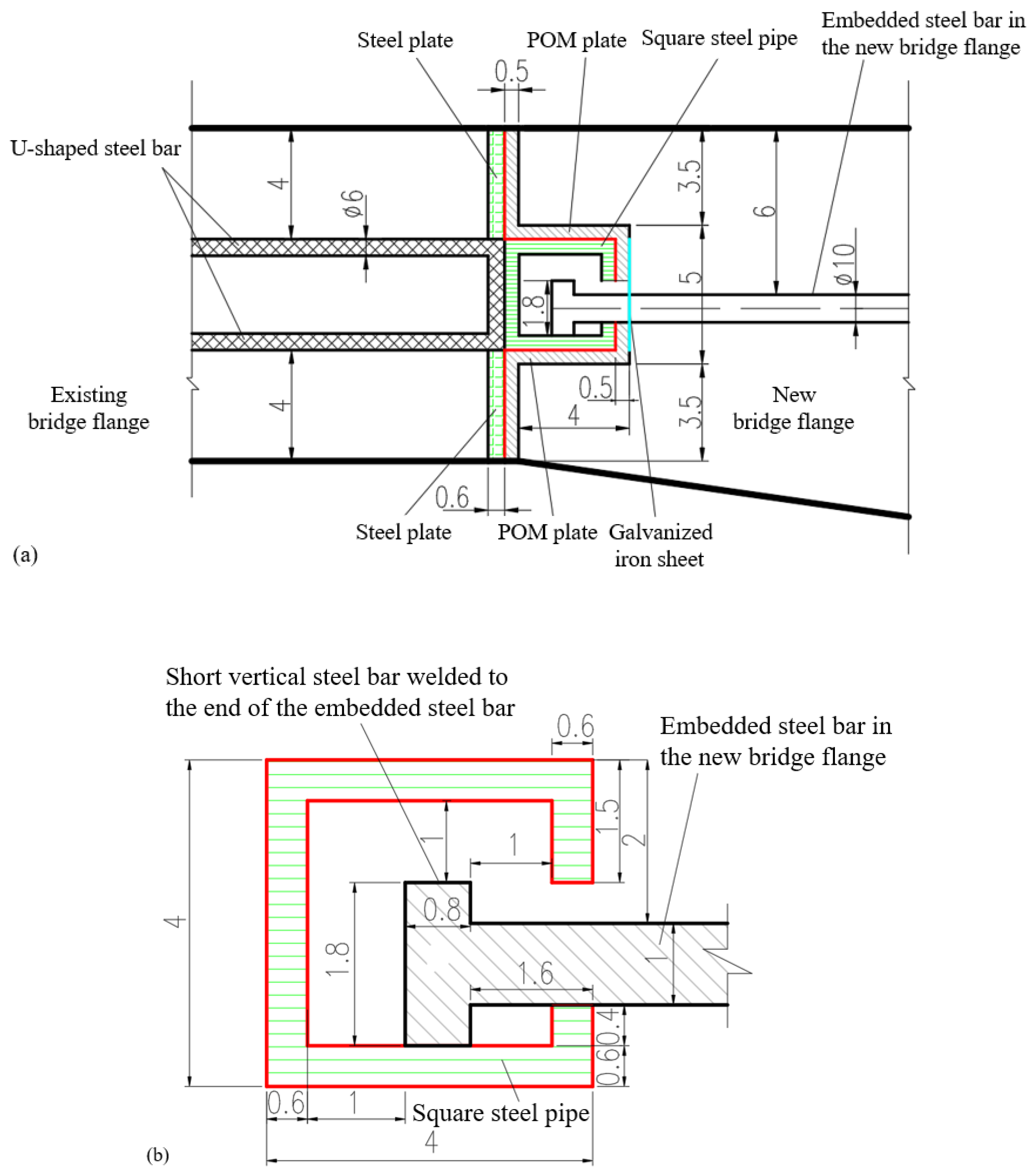
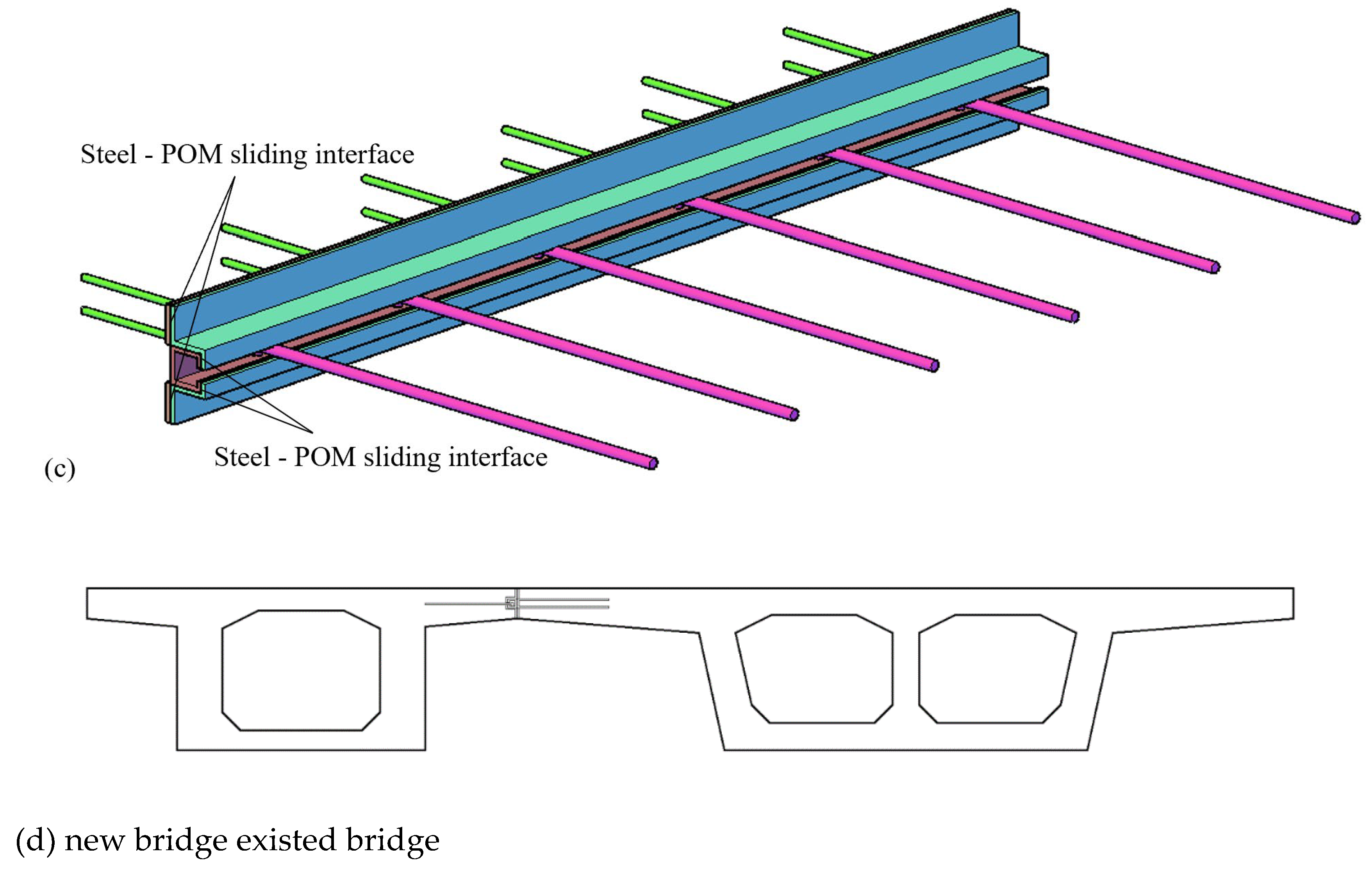
Figure 2.
Design of test model (unit: cm).
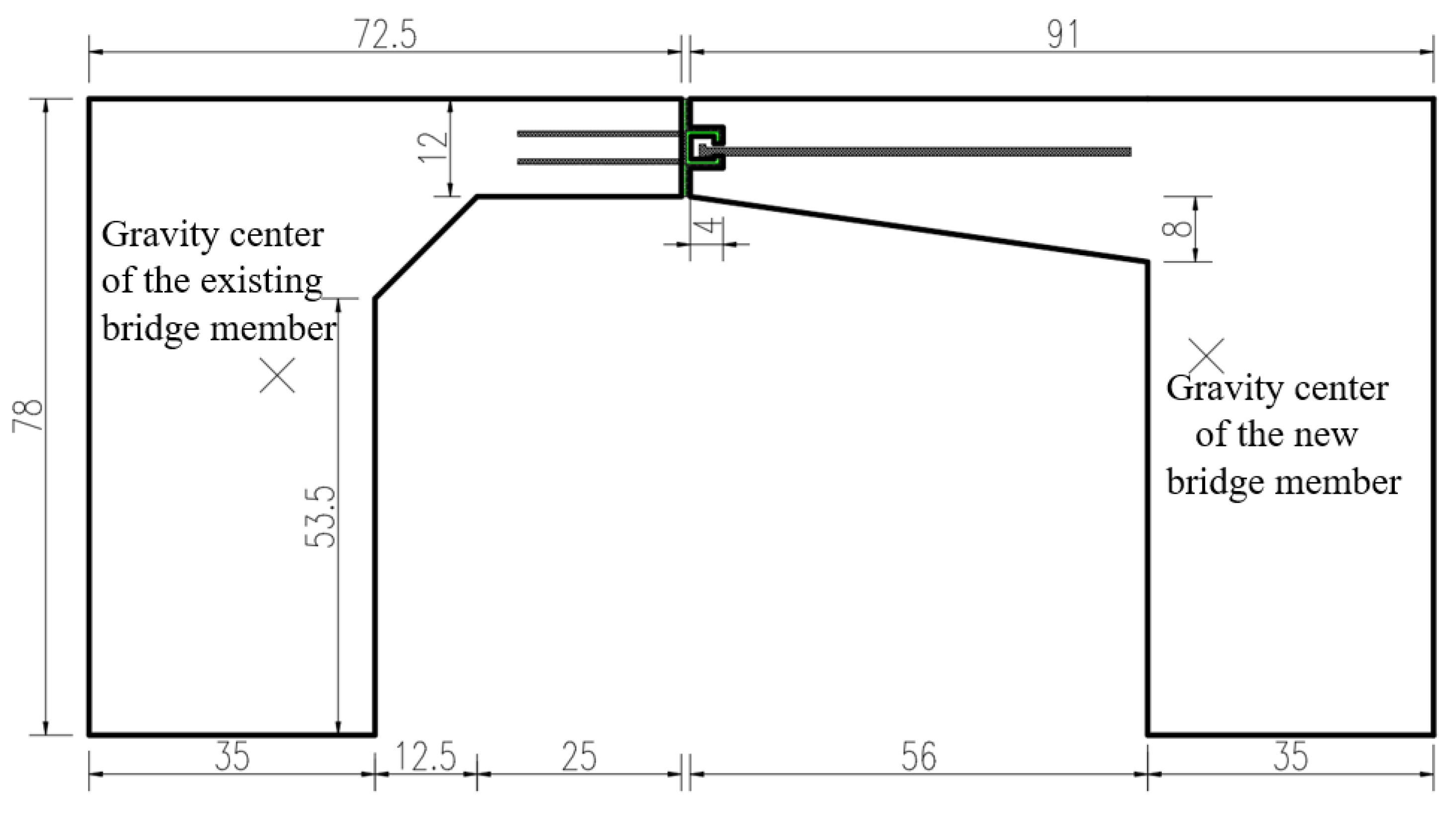
Figure 3.
Three-dimensional schematic of wheel loads application on the bridge deck.
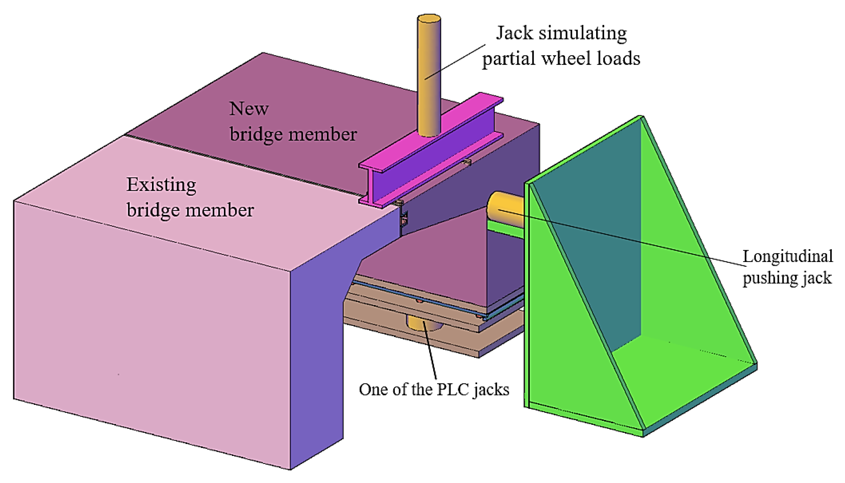
Figure 4.
Schematic diagrams of loading devices for (a) simulating longitudinal sliding effect and vertical foundation settlement; and (b) simulating longitudinal deformation of the segment.
Figure 4.
Schematic diagrams of loading devices for (a) simulating longitudinal sliding effect and vertical foundation settlement; and (b) simulating longitudinal deformation of the segment.
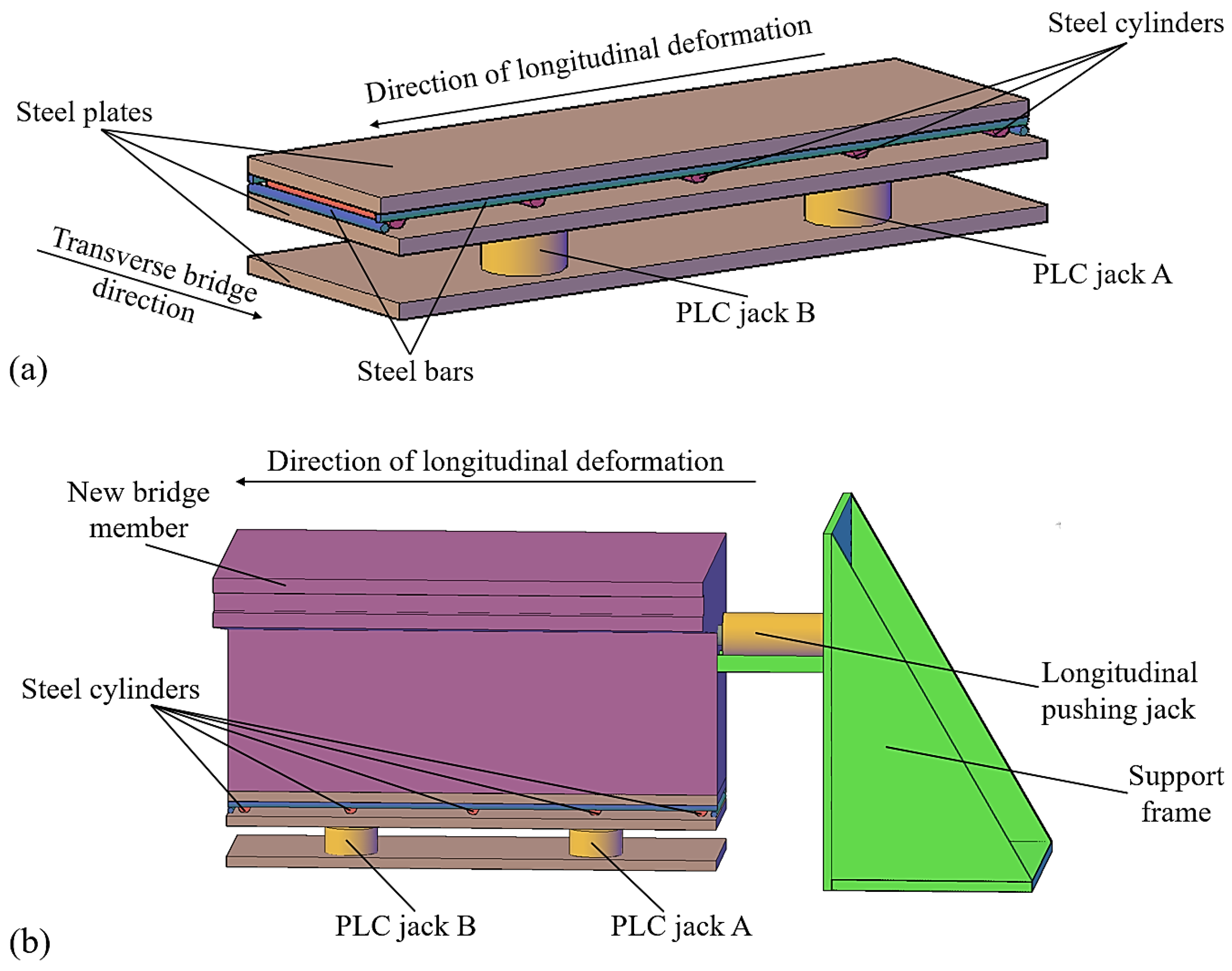
Figure 5.
Concrete stress measurement points on the front cross-section: (a) layout of strain rosettes (unit: cm); and (b) photograph of concrete stress measurement points.
Figure 5.
Concrete stress measurement points on the front cross-section: (a) layout of strain rosettes (unit: cm); and (b) photograph of concrete stress measurement points.
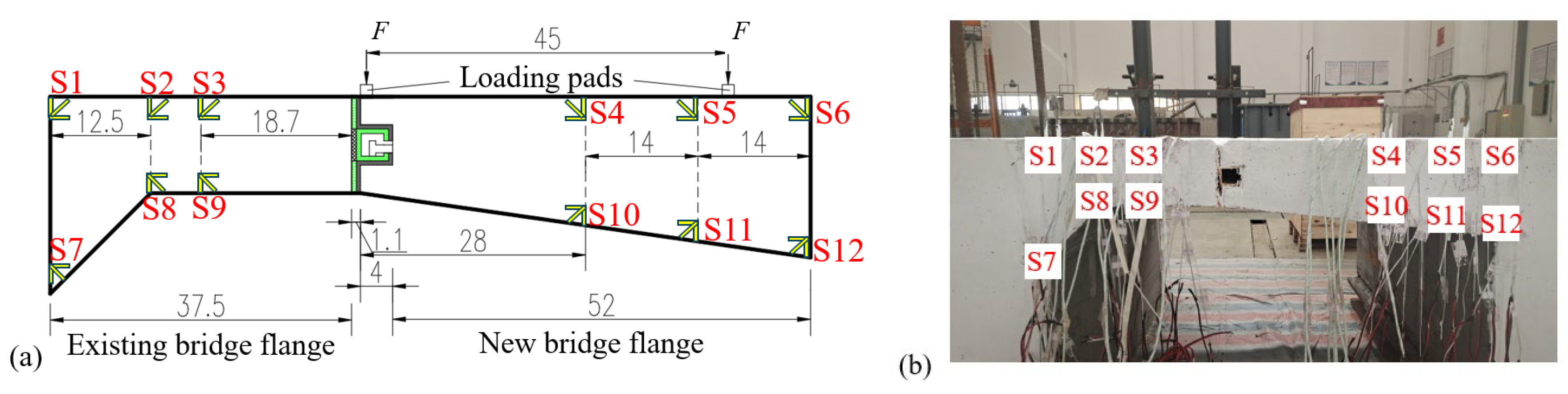
Figure 6.
Stress measurement points for steel bars (unit: cm): (a) inside the concrete at the end of the flanges; and (b) outside the concrete at the connection structure.
Figure 6.
Stress measurement points for steel bars (unit: cm): (a) inside the concrete at the end of the flanges; and (b) outside the concrete at the connection structure.
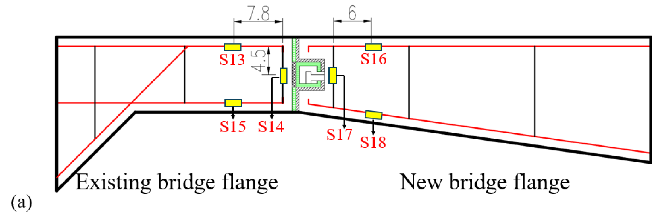
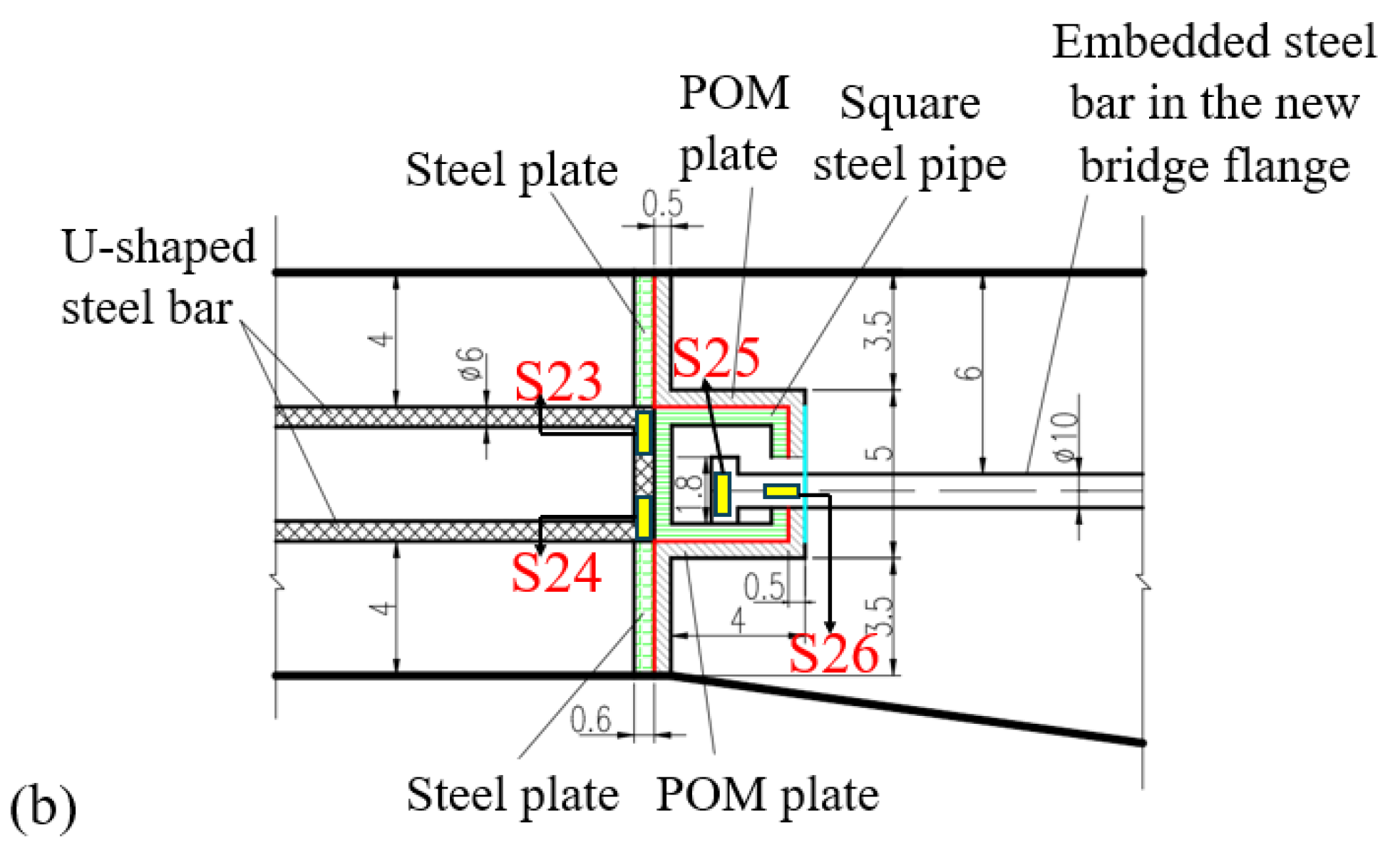
Figure 7.
Layout of stress measurement points: (a) on the upper steel plate and top surface of the square steel pipe; (b) on the lower steel plate and bottom surface of the square steel pipe.
Figure 7.
Layout of stress measurement points: (a) on the upper steel plate and top surface of the square steel pipe; (b) on the lower steel plate and bottom surface of the square steel pipe.
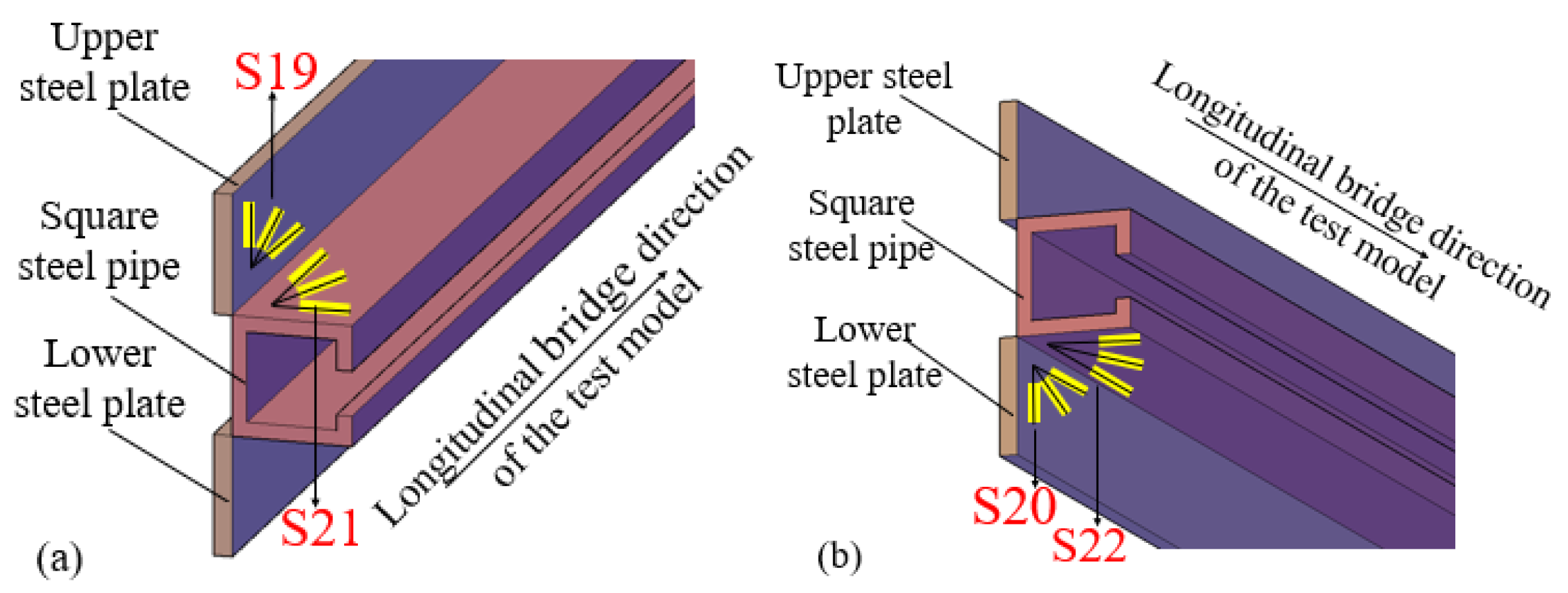
Figure 8.
Elevation layout of deflection measurement points (unit: cm).
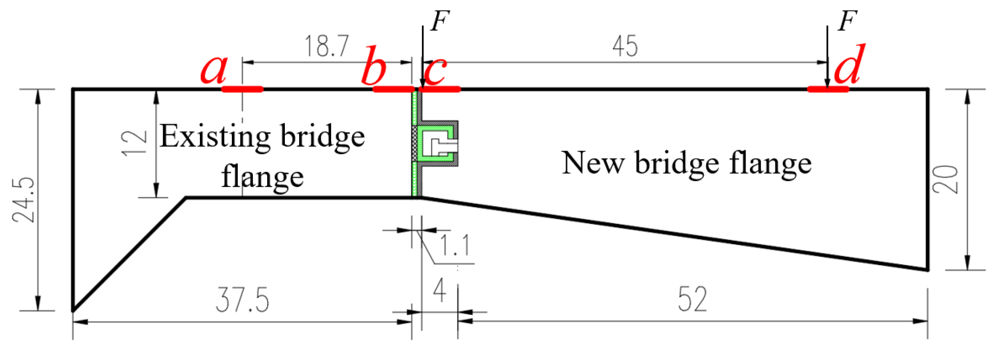
Figure 9.
Deflection distribution pattern.
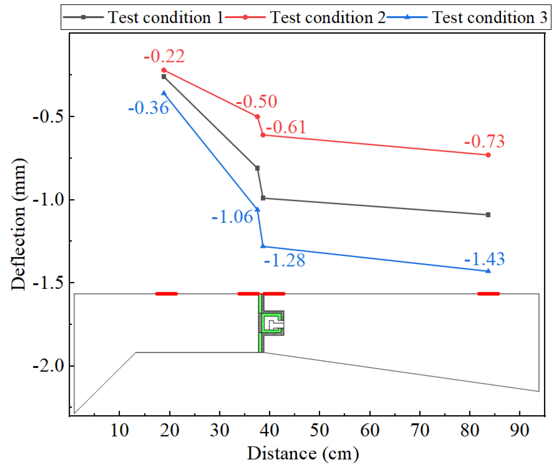
Figure 10.
Distribution of concrete principal tensile stress in the flanges.
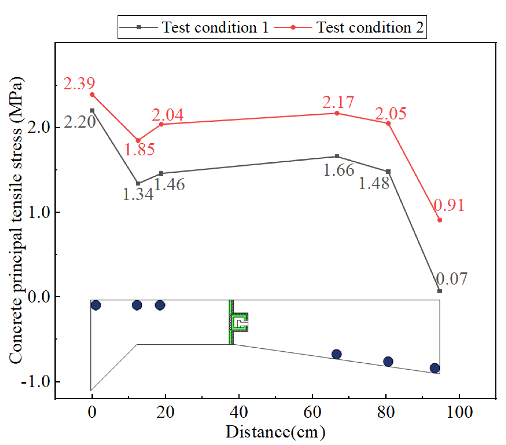
Figure 11.
Scatter plot of axial stress test data in steel bars.
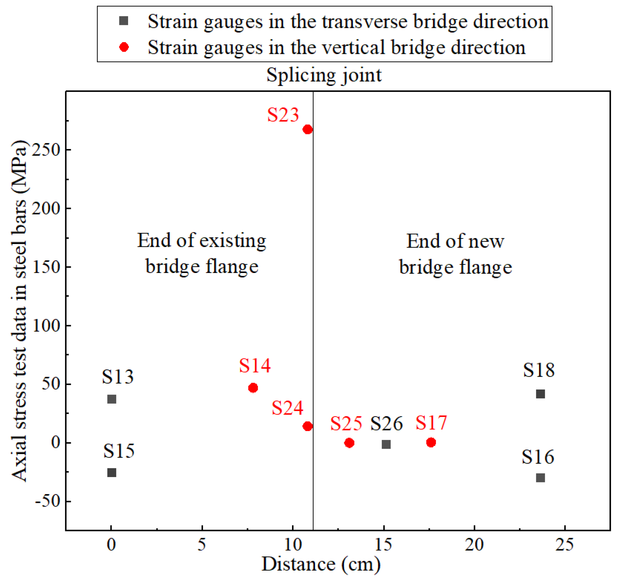
Figure 12.
Comparison of deflection test data between Condition 3 and 4.
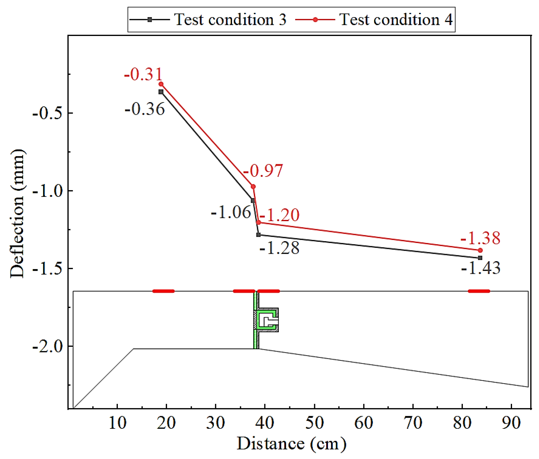
Figure 13.
Comparison of concrete first principal stress.
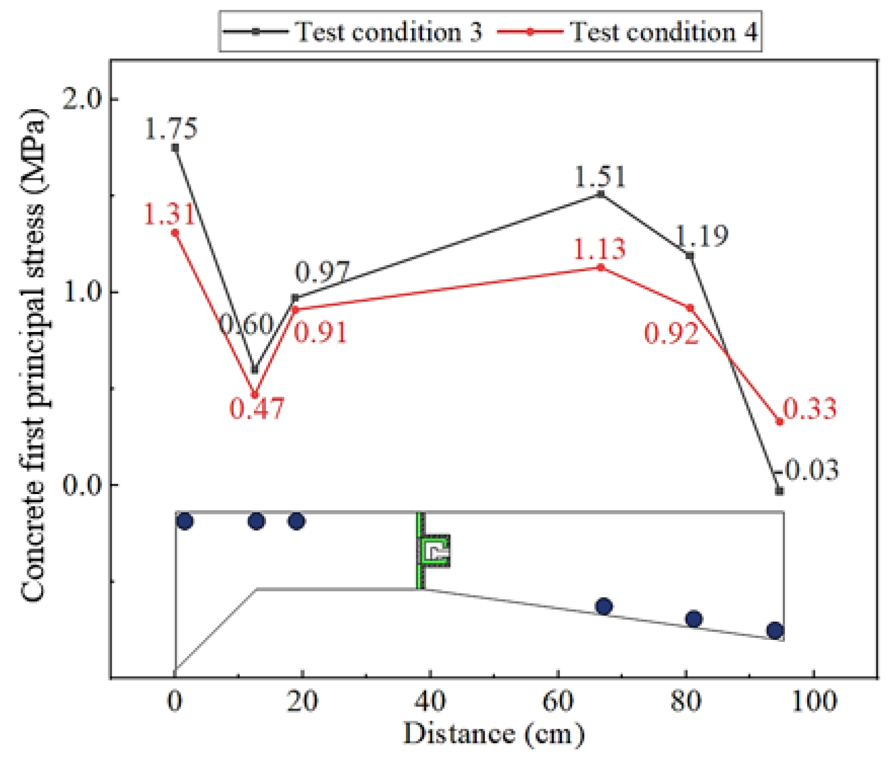
Figure 14.
Constitutive relationship curve of concrete: (a) the exponential model; and (b) the parabolic model.
Figure 14.
Constitutive relationship curve of concrete: (a) the exponential model; and (b) the parabolic model.
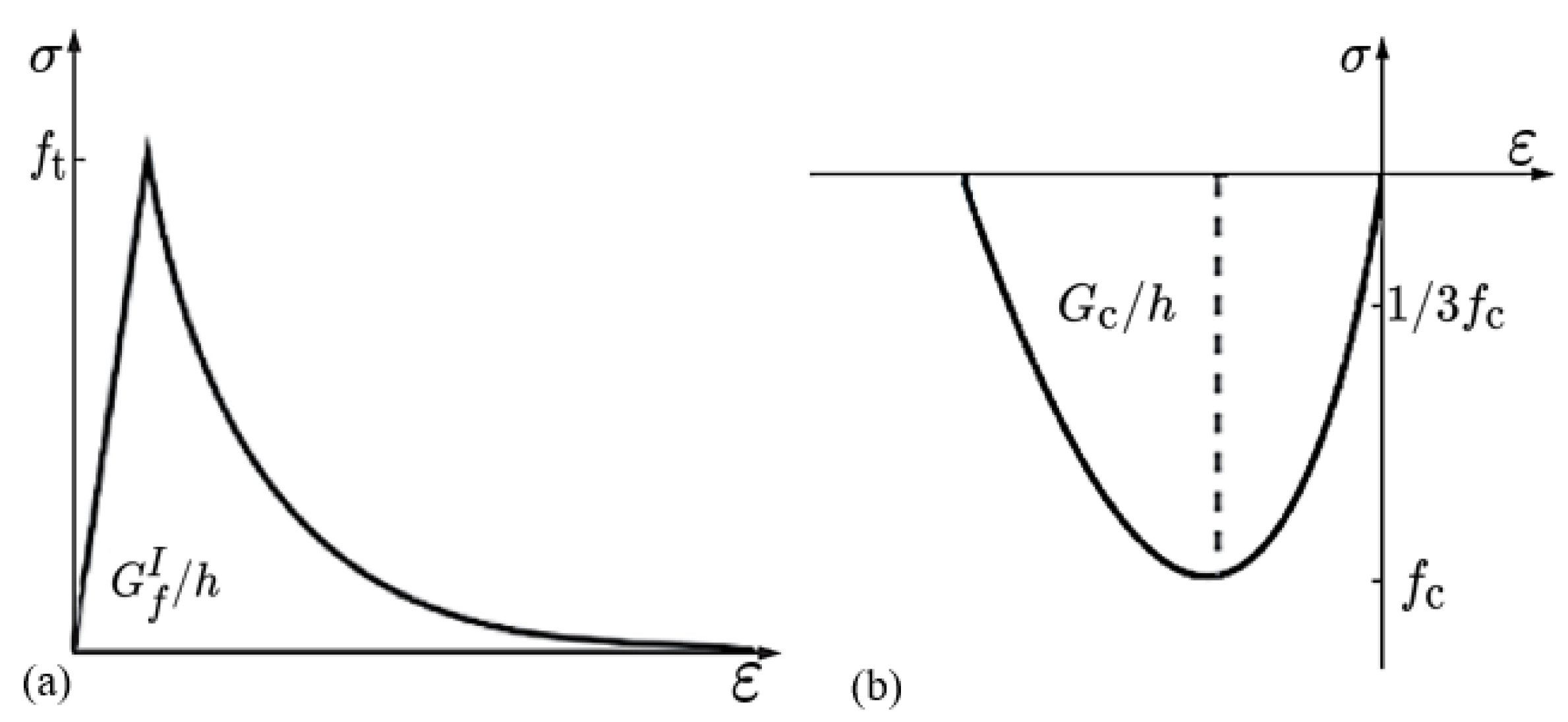
Figure 15.
Finite element model and simulated boundary conditions: (a) elevation view; (b) 3D diagram; and (c) partial enlarged detail of the connection structure.
Figure 15.
Finite element model and simulated boundary conditions: (a) elevation view; (b) 3D diagram; and (c) partial enlarged detail of the connection structure.
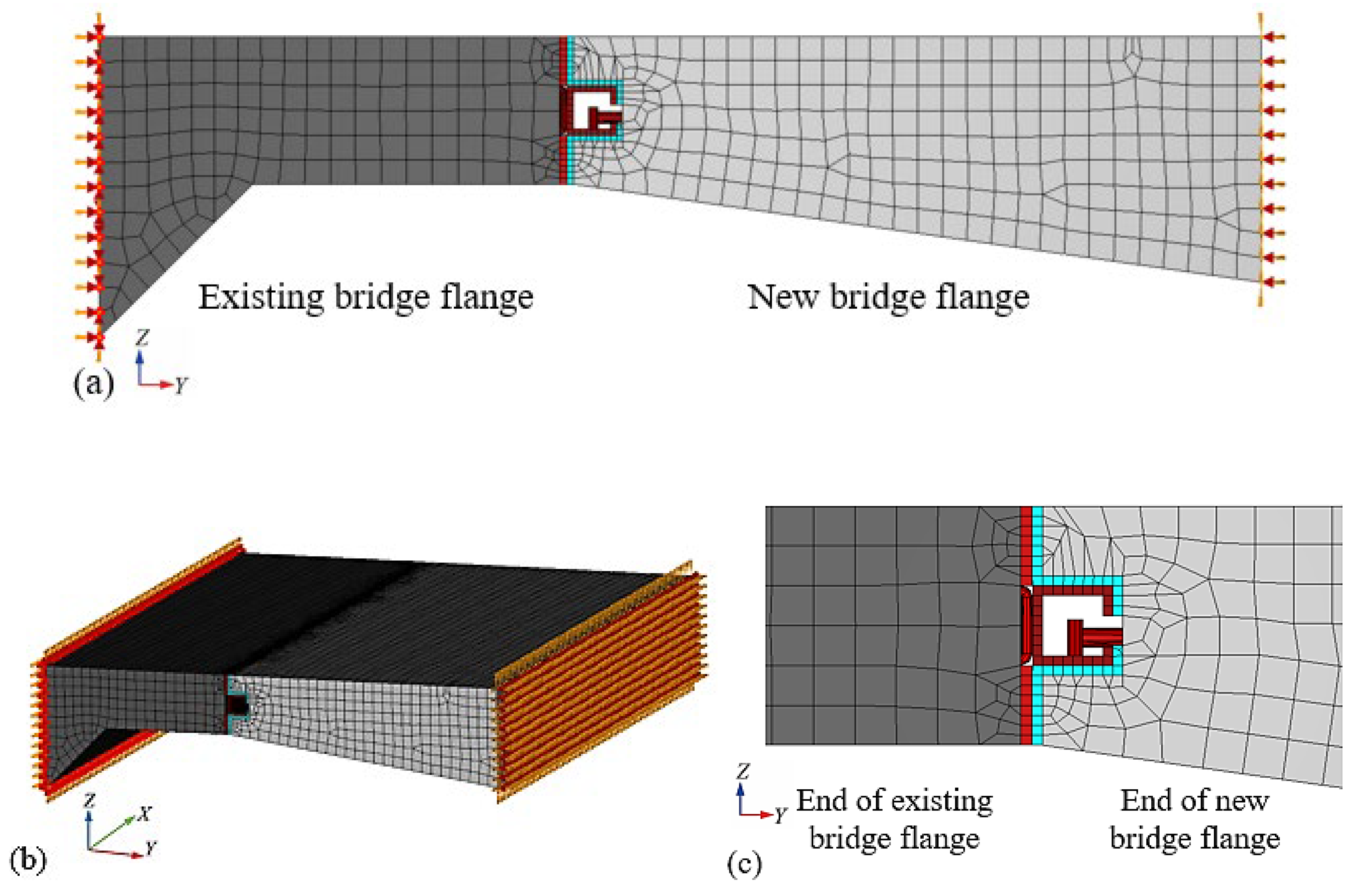
Figure 16.
Vertical deformation diagrams of each component at the loading cross-section of (unit: mm): (a) new and existing bridge flanges; (b) square steel pipe; and (c) square steel pipe and its adjacent components.
Figure 16.
Vertical deformation diagrams of each component at the loading cross-section of (unit: mm): (a) new and existing bridge flanges; (b) square steel pipe; and (c) square steel pipe and its adjacent components.
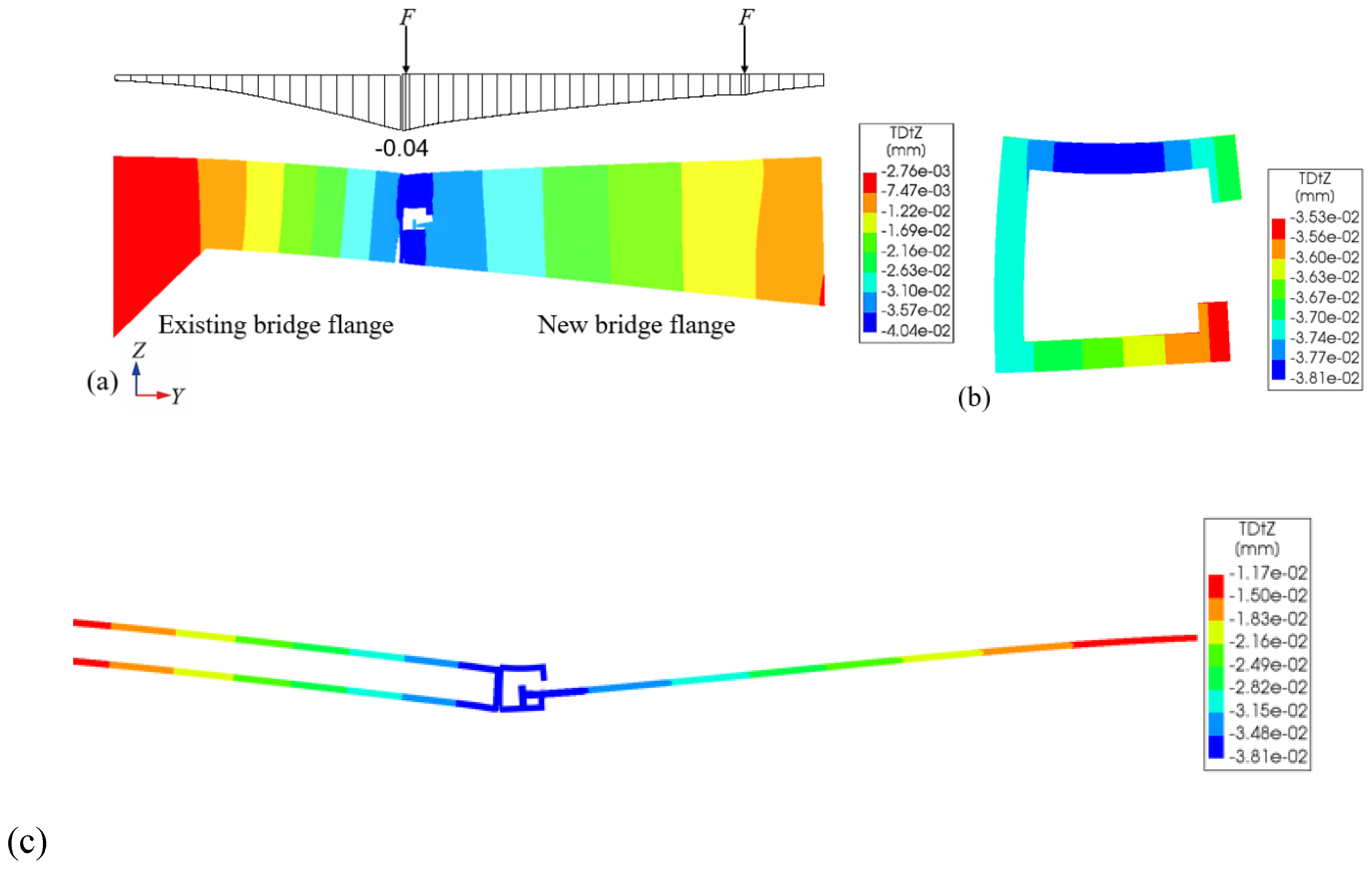
Figure 17.
Principal stress trajectory lines of (unit: MPa): (a) end of existing bridge flange; (b) end of new bridge flange; (c) end cross-section of square steel pipe; and (d) U-shaped and embedded steel bars.
Figure 17.
Principal stress trajectory lines of (unit: MPa): (a) end of existing bridge flange; (b) end of new bridge flange; (c) end cross-section of square steel pipe; and (d) U-shaped and embedded steel bars.
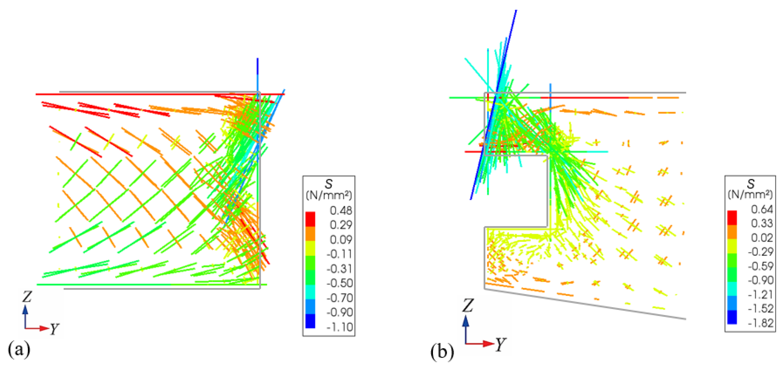
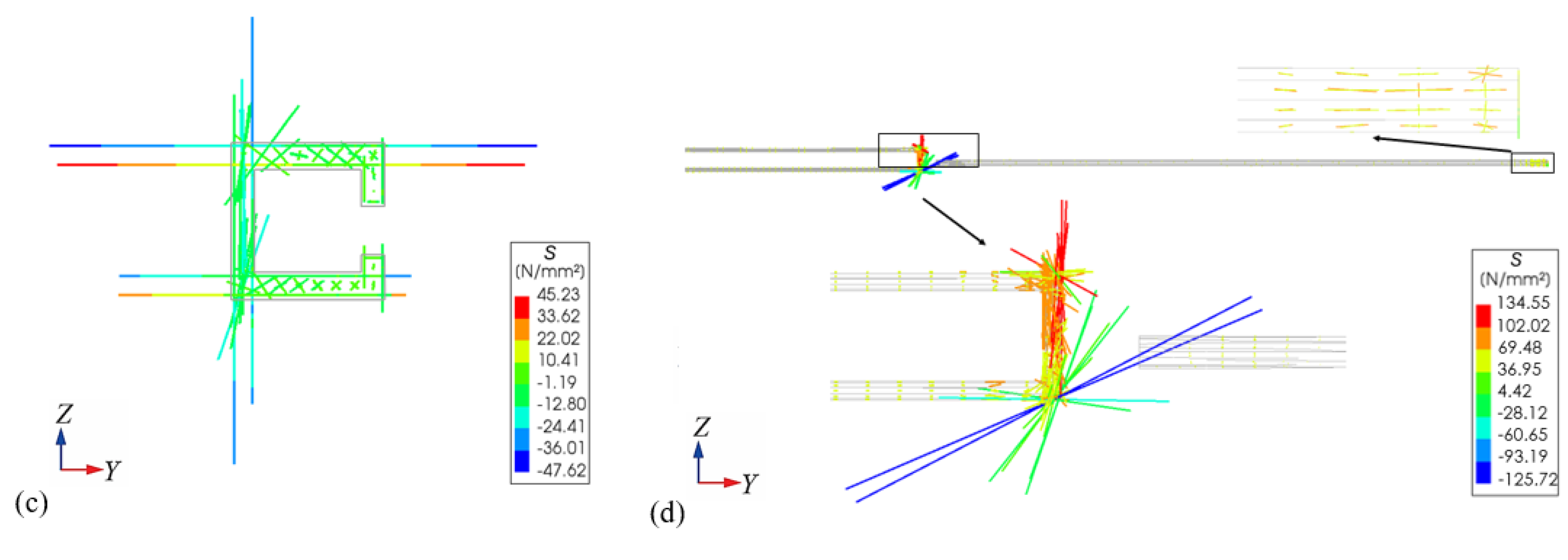

Table 1.
Key conditions achieved in the model test.
| Elastic working stage | Test conditions (No.) |
Wheel loads on the bridge deck (double-point static load) |
Uniform settlement of new bridge member | Non-uniform settlement of new bridge member | Concrete shrinkage and creep of new bridge segment | |
|---|---|---|---|---|---|---|
| PLC Jack A |
PLC Jack B |
|||||
| Elastic working stage | 1 | √ | 1mm | - | - | - |
| 2 | √ | - | 1mm | 0mm | - | |
| 3 | √ | - | 2mm | 1mm | - | |
| 4 | √ | - | 2mm | 1mm | √ | |
Table 2.
Material properties of concrete, rebar and AISI1045 steel.
| Materials | Modulus of elasticity (MPa) | Density (kg/m3) | Poisson’s ratio | Main mechanical parameters (MPa) | |
|---|---|---|---|---|---|
| C40 concrete | 3.25×10⁴ | 2.43×10³ | 0.2 | Tensile strength (design value) | 1.65 |
| Compressive strength (design value) |
18.4 | ||||
| HRB400 rebar | 2×10⁵ | 7.85×10³ | 0.3 | Yield strength (design value of tensile strength) | 330 |
| AISI1045 steel | 2.06×10⁵ | 7.85×10³ | 0.3 | Yield strength | 355 |
Disclaimer/Publisher’s Note: The statements, opinions and data contained in all publications are solely those of the individual author(s) and contributor(s) and not of MDPI and/or the editor(s). MDPI and/or the editor(s) disclaim responsibility for any injury to people or property resulting from any ideas, methods, instructions or products referred to in the content. |
© 2025 by the authors. Licensee MDPI, Basel, Switzerland. This article is an open access article distributed under the terms and conditions of the Creative Commons Attribution (CC BY) license (http://creativecommons.org/licenses/by/4.0/).
Copyright: This open access article is published under a Creative Commons CC BY 4.0 license, which permit the free download, distribution, and reuse, provided that the author and preprint are cited in any reuse.


