
Submitted:
12 February 2025
Posted:
13 February 2025
You are already at the latest version
Abstract
This paper introduces the design and evaluation of an RFID-based inventory robot that uses vision and a 3-degree-of-freedom (DOF) manipulator for dynamic antenna positioning. The robotic system is designed to enhance RFID tag detection performance and efficiency in inventory management by autonomously detecting objects, orienting an RFID antenna towards them, and executing a circular scanning motion that ensures complete coverage of the object’s surface. This paper also present a comparative analysis of three scanning strategies: (1) a conventional fixed antenna approach, where the antenna remains stationary on one side of the robot; (2) a predefined path strategy, where the manipulator moves the antenna across preset spatial points to maximize coverage; and (3) an intelligent detection and dynamic positioning method. In the latter, a pre-trained YOLO model identifies probable products and utilizes forward and inverse kinematics to precisely position the manipulator’s end effector (The antenna) to perform a tailored circular motion around the object, ensuring comprehensive RFID tag scanning. Experimental results, illustrated through comparative graphs, highlight the superior performance of the vision-assisted dynamic positioning approach. This method significantly outperforms the fixed and predefined path strategies in terms of the total number of RFID tags read over time, particularly in scenarios with varied object heights and spatial distributions. The work in this paper marks a step forward in the development of autonomous inventory robots and autonomous warehouse systems, offering enhanced capabilities for real-time inventory tracking and management.
Keywords:
n/a
; RFID
; Inventory Robots
; RFID-based Inventory
1. Introduction
Efficient inventory management is crucial for modern supply chains, where the rapid and accurate tracking of products is essential to meet the demands of global commerce. Ground inventory Autonomous Mobile Robots (AMRs) using Radio Frequency Identification (RFID) have emerged as a solution to this challenge [1], offering automated systems that navigate warehouse environments to track and manage inventory. Research in this field has matured enough to see these robots already operating in retail shops and warehouses [2,3,4,5]. However, these robots typically employ the RFID antennas on or in their chassis in a static fixed position, which limits their ability to fully scan items represented by RFID tags from all angles, especially in cluttered or densely packed environments. This limitation often results in incomplete inventory data, necessitating manual verification and reducing overall efficiency. To overcome these challenges, scientists in [6] and [7] develop autonomous inventory aerial robots (UAVs) for this task, leveraging UAVs equipped with RFID sensors to scan items placed in areas that are hard to reach and be detected by ground AMRs. Although these systems offer a broader perspective and can access areas that ground robots cannot, they are hindered by limited flight times, complex navigation in confined spaces, and the need for frequent recharging. Additionally, the accuracy of RFID readings from aerial platforms can be compromised due to the distance between the antenna and the tags, leading to incomplete or inaccurate inventory data. Scientists attempt to compromise the benefits and mitigate the limitations of UAVs and AMRs by developing Hybrid robots with the capability of ground and aerial mobility [8,9]. In research [10], scientists design a hybrid robot that combines the aerial capabilities of a UAV with the ground mobility of a wheeled platform for the problem of RFID-based 3D inventory in warehouses. Although these hybrid robots can operate in both confined spaces and across large areas makes them versatile for diverse warehouse layouts, however, these robots often face challenges related to energy consumption and coordination between their different modes, which can impact their operational endurance and require sophisticated control systems to manage their complex movements effectively. Another approach involves ground robots with advanced sensor arrays, such as the AMR Dextory robot [11]. The latter features an extendable 12-meter tower mounting an array of sensors, cameras, and LiDARs. This system can scan entire racks as the robot moves along warehouse aisles. Despite its advanced capabilities and extensive coverage range, this approach is complex and costly, requiring sophisticated infrastructure and maintenance. Moreover, the reliance on high-mounted sensors may still miss tags located in obscured or hard-to-reach areas, leading to incomplete scans. scientists in [12] developed a robot called "The MONITOR Robot" that involves the use of rotary antenna RFID inventory robots, where the RFID antenna is mounted on a rotating platform (a fixed motor) to scan in all directions. Their method did improves coverage and tag readings compared to fixed antennas, however, it remains limited by its inability to dynamically adjust the antenna’s position based on the specific geometry and location of objects. This often results in suboptimal scanning, particularly for items placed at varying heights or orientations. To address these challenges, this paper proposes a novel design for a vision-assisted dynamic antenna positioning RFID-based inventory robot with a 3DOF manipulator called (RFID-HAND robot). The proposed system combines the flexibility of a robotic arm with advanced vision-based object detection, enabling the RFID antenna to dynamically adjust its position and orientation to optimize tag detection. Unlike previous approaches, this system can detect and locate a list of items or objects using a pre-trained YOLO model, calculate the optimal antenna position using forward and inverse kinematics, and perform a circular scanning motion tailored to the object’s size and orientation. This ensures comprehensive coverage of the object’s surface, maximizing the number of RFID tags detected and representing a significant step forward in the development of autonomous inventory robots.
2. Robot Design
2.1. RFID-HAND Robot Hardware Description
The hardware description of the RFID-HAND robot can be categorized and explained into three blocks as shown in Figure 1
- Robot arms block: The robot is designed with a robotic hand offering 3 DOF, powered by three cost-effective servo motors equipped with feedback capabilities for precise and accurate movement. An RFID antenna is mounted on the end effector, allowing for efficient spatial manipulation. The joints of the robotic hand are interconnected with an elastic rubber band, capable of supporting weights up to 30 kg, which not only reduces pressure on the servos but also enhances the stall torque limit, thus optimizing the performance of each joint.
- Sensors block: The sensor array of the robot is meticulously arranged, featuring a Lidar sensor mounted atop the chassis for critical proximity detection and 3D environmental mapping. Additionally, an RGBD camera is integrated to capture both color images and depth information, enabling the robot to accurately perceive the shape, size, and distance of objects in its vicinity. The computational backbone of the robot is a cost-effective and energy-efficient single-board computer (SBC), specifically the n100, which processes sensor data, executes control algorithms, and supports advanced functionalities such as neural network-based object recognition, navigation, and localization.
- Mobility block: For mobility, the robot is equipped with two 24V high-torque motors, each fitted with hall sensors and a motion controller, ensuring precise control over the robot’s movement, velocity, and acceleration. The power system is designed for sustained operation, either via a rechargeable battery pack or an external power source, ensuring the robot’s continuous functionality.
2.2. RFID-HAND Robot Software Description
The software architecture deployed on the robotic platform is centered around the Robot Operating System 2 (ROS2) framework [13], which provides a robust and scalable foundation for complex robotic operations. The integration of the differential drive motor controller with ROS2’s control software [14] facilitates precise communication, enabling accurate odometry and controlled locomotion.
The robot’s navigation system utilizes the ROS2 Nav2 stack [15], a multilayered software that enables the creation of both local and global costmaps. These costmaps are derived from sensor data gathered by the robot’s comprehensive perception layer, allowing for sophisticated interaction with the environment. The perception layer is a critical component, comprising a meticulously arranged array of sensors designed to optimize the detection and observation of obstacles. This sensor suite includes a 360-degree LiDAR for comprehensive proximity data, an RGBD depth camera for enhanced environmental awareness through depth perception, and localization sensors, such as hall sensors integrated into the motors and an Inertial Measurement Unit (IMU), which contribute to the robot’s spatial orientation and map generation. Collectively, these sensory inputs provide the necessary data to construct and refine maps, which are essential for effective navigation and obstacle avoidance. The navigation and path-planning module leverages data from the perception layer to compute optimal trajectories toward predefined goals while dynamically avoiding obstacles. This capability is achieved through path-planning algorithms that process real-time sensor data to assess the environment, analyze current conditions, and determine the most efficient and safe paths for the robot’s movement. In addition to navigation, the software system includes a custom-designed controller for the robotic arms mounted on the platform. This controller acts as an intermediary, integrating inverse kinematics algorithms from ROS2 MoveIt [16] with essential data on joint angles, velocities, and feedback, ensuring precise control of the robot’s arms. Through its interface with ROS2 MoveIt, the custom controller translates high-level motion plans into executable commands, enabling the robot’s arms to operate with accuracy and responsiveness. Moreover, The robot’s software system incorporates an algorithm that utilizes detection-information from a pre-trained YOLO model [17] to identify potential warehouse items within its environment. Upon detecting an item, the algorithm computes the optimal kinematic movements for the robot’s 3-DOF arm, which is equipped with an RFID antenna at its end effector. The algorithm precisely orients the arm toward the detected item, ensuring accurate targeting. Once aligned, the arm performs a controlled circular motion around the item’s perimeter, effectively covering its entire surface area to maximize RFID scanning efficiency and ensure comprehensive data capture of the item.
3. Technical Overview
The robot employs a pre-trained YOLO9 model to detect boxes and similar warehouse products that are attached to RFID tags. YOLO9 provides bounding boxes and pixel positions of detected objects in the camera’s image plane. To interact with these objects, the robot translates the 2D-pixel positions into 3D world coordinates utilizing the information of the depth point supplied by the camera, enabling the robotic arm to orient its end effector accurately. The depth value is obtained from the RGB-D depth camera corresponding to the center pixel . The camera’s intrinsic matrix K is defined as:
where and are the focal lengths, and is the optical center. For a detected object’s bounding box with the top-left corner and the bottom-right corner , the center of the bounding box in pixel coordinates and the 3D world coordinates of the detected object can be derived in Equations (2) and (3)
A position of the center of a detected object is therefore extracted with coordinates . Using trigonometry equations in Equations (4), (5), (6), and (8) and as illustrated in Figure 2 we compute the position along the line . h is the desired point position to move the end effector (RFID antenna) to a point at the center of the detected object. We assume that which is the angle of the elbow joint shown in Figure 2 is as the robotic arm should be extended to the maximum for forming a pointing shape towards a target.
For further manipulation of the robotic arm Forward and Inverse kinematics model is used to move the frames as such as shown in Figure 2. To represent the kinematic chain, we use the Denavit-Hartenberg (DH)[18] convention to define each joint’s transformation matrix. Using the DH parameters, the transformation matrices for each joint T1, T2, and T3 respectively are represented as Equations (9)–(11).
The overall transformation from the base to the end-effector is given by Equation 12
Inverse kinematics involves determining the joint angles given the desired position in the cartesian coordinate system and can be extracted using the previous equations.
From the obtained transformation matrix T, the position of the end-effector is defined as .
The computed joint angles are fed into the robotic arm controller, which adjusts the arm’s position dynamically. To optimize RFID tag scanning and inventory management, the robot ensures that the RFID antenna at the end effector points toward and covers entirely the detected object. To move the end effector in a circular motion around the product, the robot must adjust the angles , , and dynamically. The circle’s radius must be appropriate to cover the product surface, with the center at . From the given boundary box of the detected item, the distance between the maximum edge of the boundary box to the center would be considered as the radius r. The desired circular motion path that the end effector would need to follow is a set of consecutive points defined as . The parametric equations for the circular path are shown in Equation (13)
where t ranges from 0 to .
4. Experiments
4.1. Short Aile Low Shelves Scanning
The objective of experiment Section 4.1 is to assess the comparative effectiveness of two RFID scanning approaches for inventory management. This study specifically evaluates the performance of the RFID-HAND robot using a static RFID antenna versus a predefined path strategy, where the manipulator moves the antenna across preset spatial points. The primary metric of comparison is the number of RFID tags detected while scanning shelves containing tagged boxes in a controlled environment. The experiment was conducted in a controlled laboratory, with shelves arranged along one side, each containing boxes with RFID tags placed inside. The robot navigated a given path, conducting two distinct experiments in the scenario illustrated in Figure 3.
4.1.1. Fixed Antenna
In experiment Section 4.1.1, the robot was programmed to navigate in a straight line along the aisle, maintaining a constant speed. The antenna was fixed in one position, oriented perpendicular to the shelves to scan for RFID tags as shown in Figure 4. The robot made a single pass navigating along the aisle, recording the number of RFID tag reads.
4.1.2. Articulated Antenna
In experiment Section 4.1.2, the robot was programmed to navigate the same straight line path along the aisle at the same speed as in Experiment Section 4.1.1. As the robot moved, the robotic arm articulated in 3D space, moving the antenna in a sweeping motion to cover a broader spatial plane. The motion pattern of the arm was pre-programmed to ensure consistent coverage as shown in Figure 5. The robot made a single pass along the aisle, recording the number of RFID tag reads.
Upon completion of both experiments, the RFID read data were analyzed to determine the number of unique RFID tags detected in each scenario. The results in Figure 6, demonstrated a significant difference in the number of RFID tags detected between the two scanning methods. The fixed antenna position resulted in a limited detection range, with a total of 117 tags read, however, the articulated robotic arm significantly increased the coverage area, resulting in 438 tags read from 500 total placed tags in the environment.
The articulated antenna setup showed a higher number of RFID reads, indicating improved spatial coverage and detection capability. This improvement is attributed to the dynamic motion of the antenna, which allowed for better orientation and positioning relative to the tags.
4.2. Tall Ailes High Shelves Scanning
The objective of experiment Section 4.2 is to compare the effectiveness and performance of the two different RFID scanning methods for inventory management as in experiments Section 4.1.1 and Section 4.1.2 in addition to an intelligent detection and dynamic positioning method, where a pre-trained YOLO model identifies probable products and utilizes forward and inverse kinematics to precisely position the manipulator’s end effector (The antenna) to perform a tai- lored circular motion around the object, ensuring comprehensive RFID tag scanning. The experiments were conducted in a controlled warehouse aisle with high and low placed shelves arranged along one side as shown in Figure 7. Each shelf contained boxes with RFID tags placed inside. The robot navigated along the aisle, performing two separate experiments:
4.2.1. Fixed Antenna
As in experiment Section 4.1, the robot also was programmed to navigate in a straight line along the aisle, maintaining a constant speed. The antenna was fixed in one position, oriented perpendicular to the shelves to scan for RFID tags. The robot made a single pass along the aisle, recording the number of RFID tag reads from both high and low shelves.
4.2.2. Articulated Antenna
As in experiment Section 4.2, the robot was programmed to navigate the same path and with the same speed along the aisle at the same speed as in Experiment Section 4.2. As the robot moved, the robotic arm articulated in 3D space, moving the antenna in a sweeping motion to cover both high and low shelves. The same pre-programmed motion pattern of the arm was used to ensure consistent coverage of all shelf levels. The robot made a single pass along the aisle, recording the number of RFID tag reads from both high and low shelves.
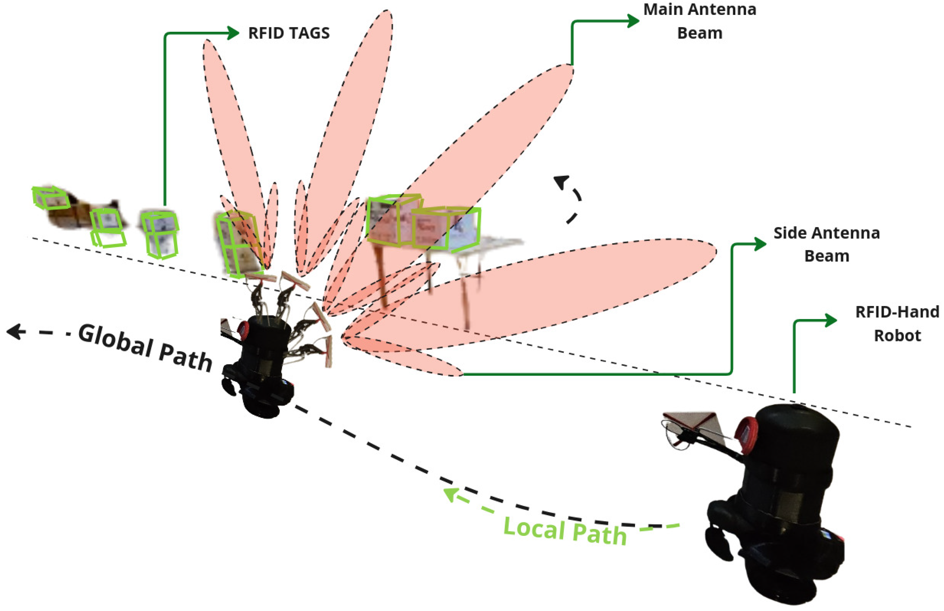
4.2.3. Dynamic Movement Articulated Antenna
For experiment Section 4.2.3, the robot was programmed to navigate the same straight-line path along the aisle at the same speed as in previous experiments. As the robot moved, utilizing the information from the detections from the YOLO model the algorithm dynamically guided the robotic arm, adjusting the antenna’s main radiation lobe toward the detected boxes with RFID tags in real-time then performing a controlled circular motion around the item’s perimeter, effectively covering its entire surface area as explained in Section 2.2. The robot made a single pass along the aisle, recording the number of RFID tag reads from both high and low shelves.
Figure 9.
A Graph of the resulted RFID tag readings from the robot with fixed antenna in experiment Section 4.2 and articulated antenna in experiment Section 4.2.2.
Figure 9.
A Graph of the resulted RFID tag readings from the robot with fixed antenna in experiment Section 4.2 and articulated antenna in experiment Section 4.2.2.
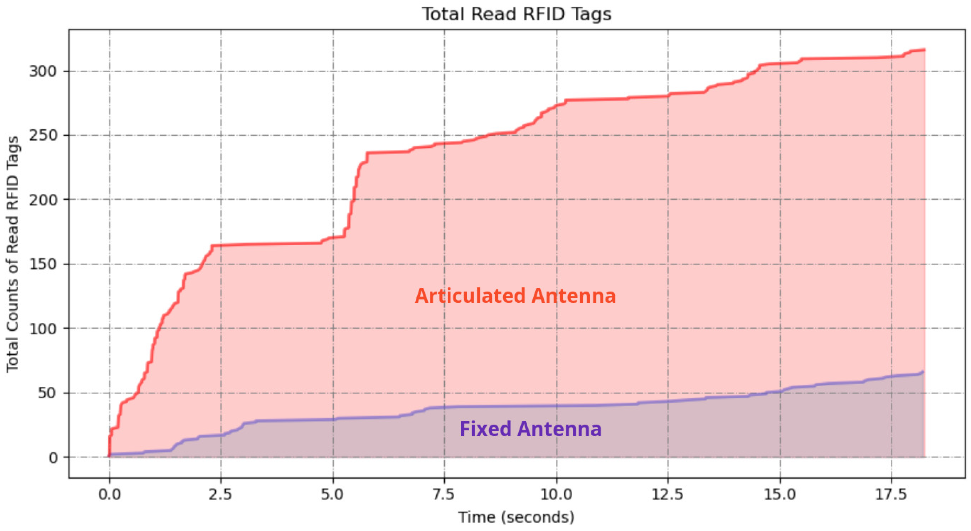
Figure 10.
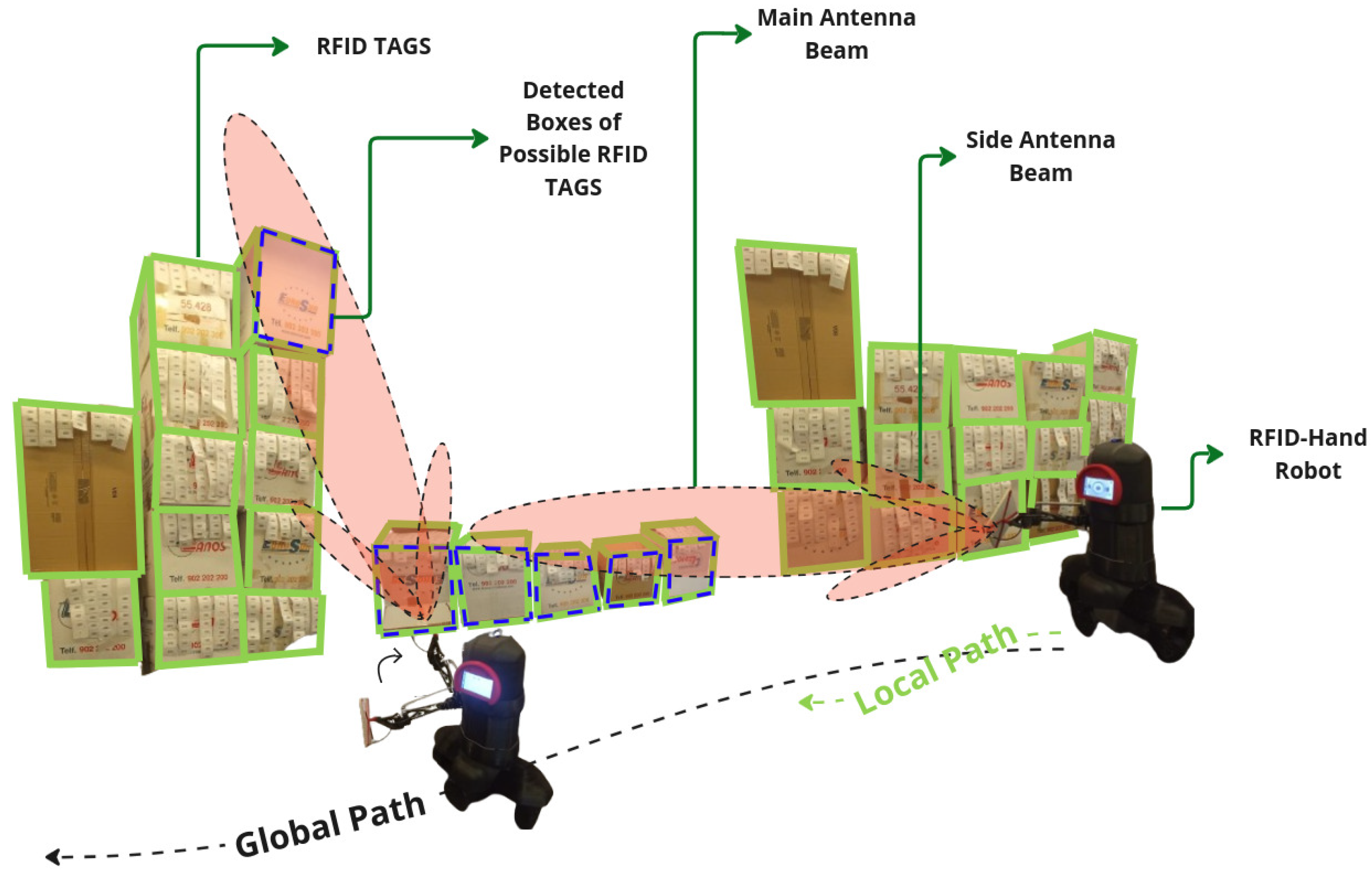
A descriptive illustration of the RFID-HAND robot performing inventory with an dynamic moving articulated antenna.
Figure 10.
A descriptive illustration of the RFID-HAND robot performing inventory with an dynamic moving articulated antenna.
The results demonstrated significant differences in the number of RFID tags detected between the three scanning methods, particularly for the high shelves.
Figure 11.
A Graph of the resulted RFID tag readings from the robot with fixed antenna in experiment Section 4.2, articulated antenna in experiment Section 4.2.2, and articulated antenna in experiment Section 4.2.3.
Figure 11.
A Graph of the resulted RFID tag readings from the robot with fixed antenna in experiment Section 4.2, articulated antenna in experiment Section 4.2.2, and articulated antenna in experiment Section 4.2.3.
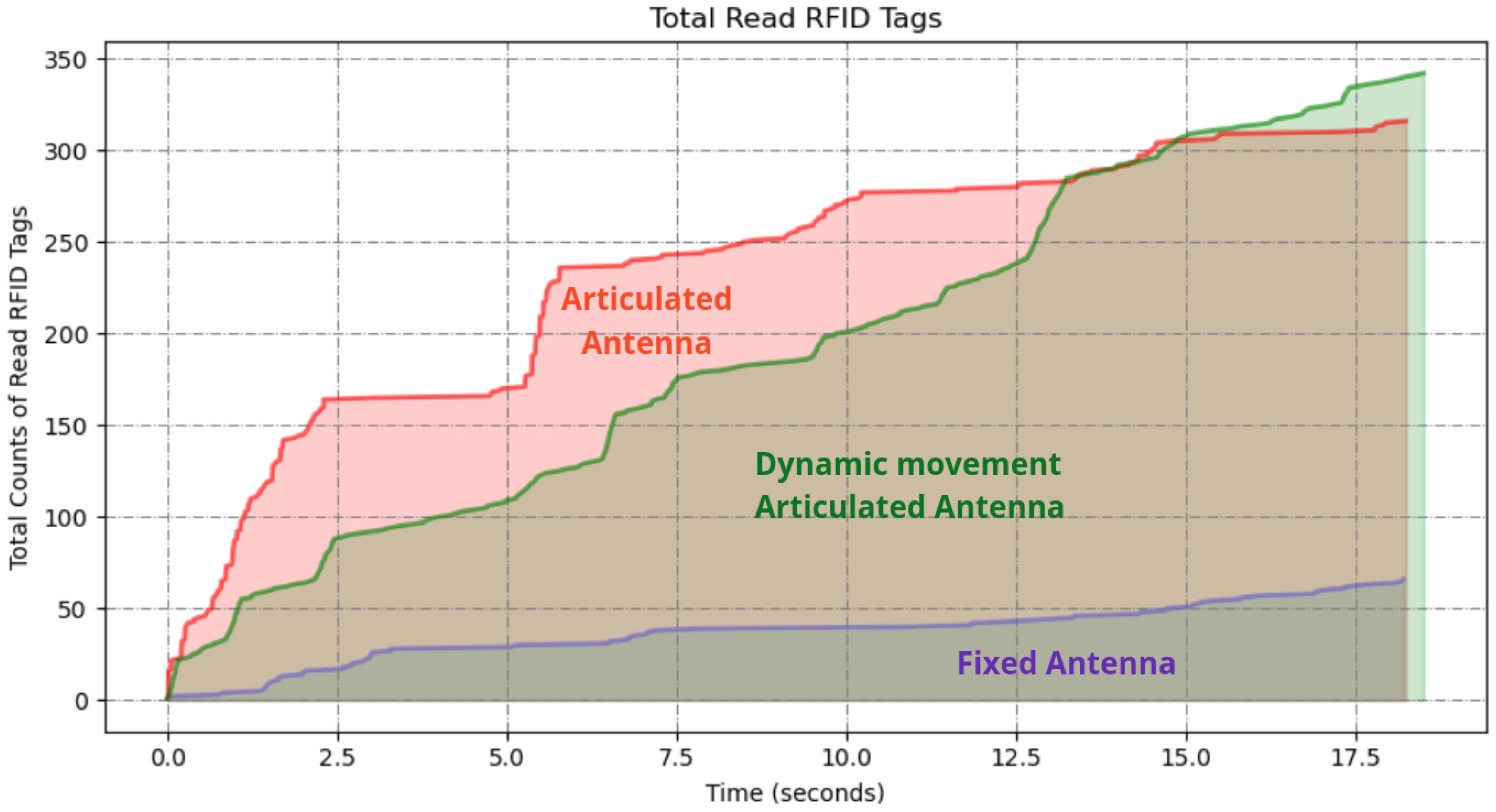
The fixed antenna position as in experiment Section 4.2 resulted in a limited detection range, with a total of 67 tags read from high and low shelves. The programmed motion of the articulated arm increased the coverage area, resulting in a total of 314 tags read RFID tags read from shelves from a total of 350 RFID tags placed. However, the vision-assisted dynamic antenna positioning further increased the coverage area. The approach outperformed the others resulting in 343 tags read from all shelves.
5. Conclusions
In this study, we presented the design and implementation of a vision-assisted dynamic antenna positioning RFID-based inventory robot utilizing a 3DOF manipulator. The robot integrates a 3DOF arm with an RFID antenna at its end effector, capable of detecting and scanning objects within a warehouse environment. Our approach leverages both forward and inverse kinematics to precisely position the antenna, allowing for a comprehensive scan of RFID tags through circular motion tailored to the object’s size. The comparative analysis demonstrated that our proposed method outperforms traditional fixed antenna configurations and predefined movement strategies in terms of tag detection efficiency and coverage. Specifically, the dynamic positioning and targeted scanning enabled by YOLO-based object detection significantly increased the number of RFID tags read across various object sizes and heights, marking a substantial advancement in inventory management robotics.
6. Future Work
Future research will focus on further refining the robot’s object detection and antenna positioning algorithms to enhance accuracy and reduce processing time. Additionally, we aim to explore the integration of machine learning techniques to adapt the scanning patterns based on real-time feedback, potentially improving performance in highly cluttered environments. Another area of interest is the expansion of the robot’s capabilities to handle a broader range of object shapes and materials, as well as the development of multi-robot systems for cooperative inventory tasks. Ultimately, the goal is to create a more autonomous and adaptable inventory management solution that can operate efficiently in diverse and dynamic warehouse settings.
References
- Motroni, A.; Buffi, A. RFID Robots and Vehicles for Item Inventory and Localization. In Proceedings of the 2023 17th European Conference on Antennas and Propagation (EuCAP), 2023, pp. 1–5. [CrossRef]
- Gareis, M.; Parr, A.; Trabert, J.; Mehner, T.; Vossiek, M.; Carlowitz, C. Stocktaking Robots, Automatic Inventory, and 3D Product Maps: The Smart Warehouse Enabled by UHF-RFID Synthetic Aperture Localization Techniques. IEEE Microwave Magazine 2021, 22, 57–68. [Google Scholar] [CrossRef]
- Morenza-Cinos, M.; Casamayor-Pujol, V.; Soler-Busquets, J.; Sanz, J.L.; Guzmán, R.; Pous, R. Development of an RFID inventory robot (AdvanRobot). Robot Operating System (ROS) The Complete Reference (Volume 2) 2017, pp. 387–417.
- Sharma, R.; Patange, A.D.; Padalghare, R.; Kale, R.C. Development of LiDAR operated inventory control and assistance robot. Proceedings of the Institution of Mechanical Engineers, Part E: Journal of Process Mechanical Engineering 2024, 238, 192–202. [Google Scholar] [CrossRef]
- Zhang, J.; Lyu, Y.; Roppel, T.; Patton, J.; Senthilkumar, C. Mobile robot for retail inventory using RFID. In Proceedings of the 2016 IEEE international conference on Industrial technology (ICIT). IEEE, 2016, pp. 101–106.
- Alajami, A.A.; Moreno, G.; Pous, R. Design of a UAV for Autonomous RFID-Based Dynamic Inventories Using Stigmergy for Mapless Indoor Environments. Drones 2022, 6. [Google Scholar] [CrossRef]
- Beul, M.; Droeschel, D.; Nieuwenhuisen, M.; Quenzel, J.; Houben, S.; Behnke, S. Fast Autonomous Flight in Warehouses for Inventory Applications. IEEE Robotics and Automation Letters 2018, 3, 3121–3128. [Google Scholar] [CrossRef]
- Alajami, A.A.; Santa Cruz, L.D.; Pous, R. Design of an Energy-Efficient Self-Heterogeneous Aerial-Ground Vehicle. In Proceedings of the 2023 9th International Conference on Automation, Robotics and Applications (ICARA). IEEE, 2023, pp. 213–218.
- Cao, M.; Xu, X.; Yuan, S.; Cao, K.; Liu, K.; Xie, L. DoubleBee: A Hybrid Aerial-Ground Robot with Two Active Wheels. In Proceedings of the 2023 IEEE/RSJ International Conference on Intelligent Robots and Systems (IROS), 2023, pp. 6962–6969. [CrossRef]
- Alajami, A.A.; Perez, F.; Pous, R. The Design of an RFID-Based Inventory Hybrid Robot for Large Warehouses. In Proceedings of the 2024 9th International Conference on Control and Robotics Engineering (ICCRE), 2024, pp. 50–54. [CrossRef]
- Dexory. Dexory Inventory Robot. https://www.dexory.com/, 2024. Accessed: 2024-08-09.
- Bernardini, F.; Motroni, A.; Nepa, P.; Tripicchio, P.; Buffi, A.; Del Col, L. The MONITOR Project: RFID-based Robots enabling real-time inventory and localization in warehouses and retail areas. In Proceedings of the 2021 6th International Conference on Smart and Sustainable Technologies (SpliTech). IEEE, 2021, pp. 1–6.
- Macenski, S.; Foote, T.; Gerkey, B.; Lalancette, C.; Woodall, W. Robot Operating System 2: Design, architecture, and uses in the wild. Science Robotics 2022, 7, eabm6074. [Google Scholar] [CrossRef] [PubMed]
- Christoph Fröhlich. Ros2 control framework. 2022.
- S. Macenski, T. Moore, A.M. From the desks of ROS maintainers: A survey of modern & capable mobile robotics algorithms in the robot operating system 2. Robotics and Autonomous Systems 2023.
- M.Görner.; R.Haschke. “Moveit! task constructor for task-level motion planning. IEEE Intl. Conf. on Robotics and Automation 2019.
- Redmon, J.; Divvala, S.; Girshick, R.; Farhadi, A. You Only Look Once: Unified, Real-Time Object Detection. In Proceedings of the 2016 IEEE Conference on Computer Vision and Pattern Recognition (CVPR); 2016; pp. 779–788. [Google Scholar] [CrossRef]
- Balasubramanian, R. The Denavit Hartenberg Convention. USA: Robotics Insitute Carnegie Mellon University 2011.
Figure 1.
RFID-HAND hardware description.
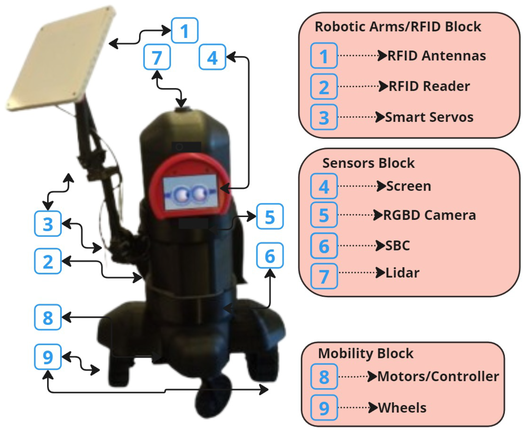
Figure 2.
(a) is an illustration of the joints, angles, lengths, and circular movement of the robotic hand towards the detected product. (b) Is an illustration of the trigonometry parameters to calculate the position .
Figure 2.
(a) is an illustration of the joints, angles, lengths, and circular movement of the robotic hand towards the detected product. (b) Is an illustration of the trigonometry parameters to calculate the position .
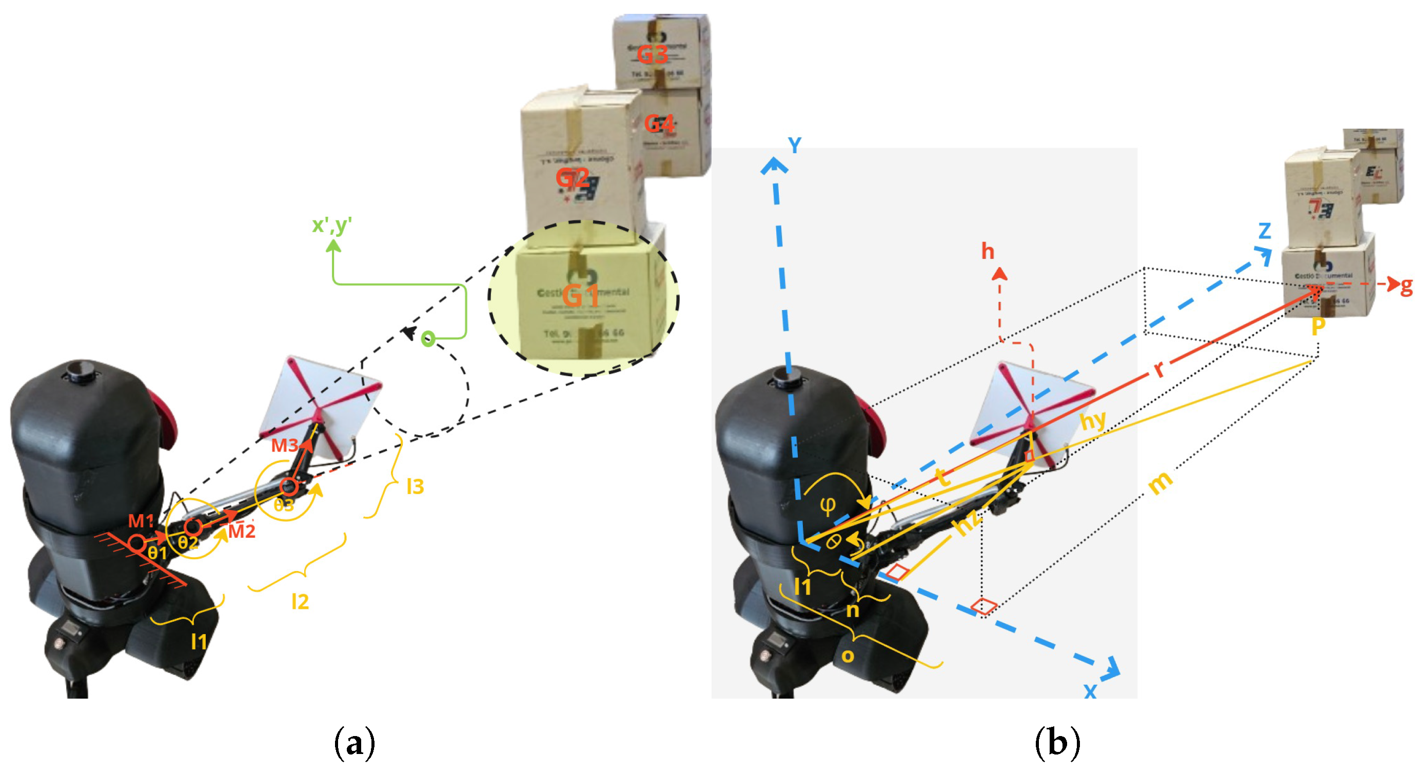
Figure 3.
Illustration of the controlled warehouse scenario.
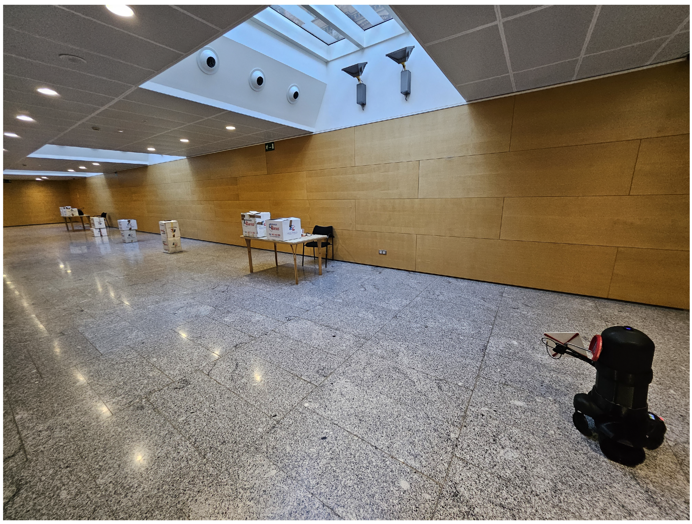
Figure 4.
A descriptive illustration of the RFID-HAND robot performing inventory with a fixed antenna.
Figure 4.
A descriptive illustration of the RFID-HAND robot performing inventory with a fixed antenna.
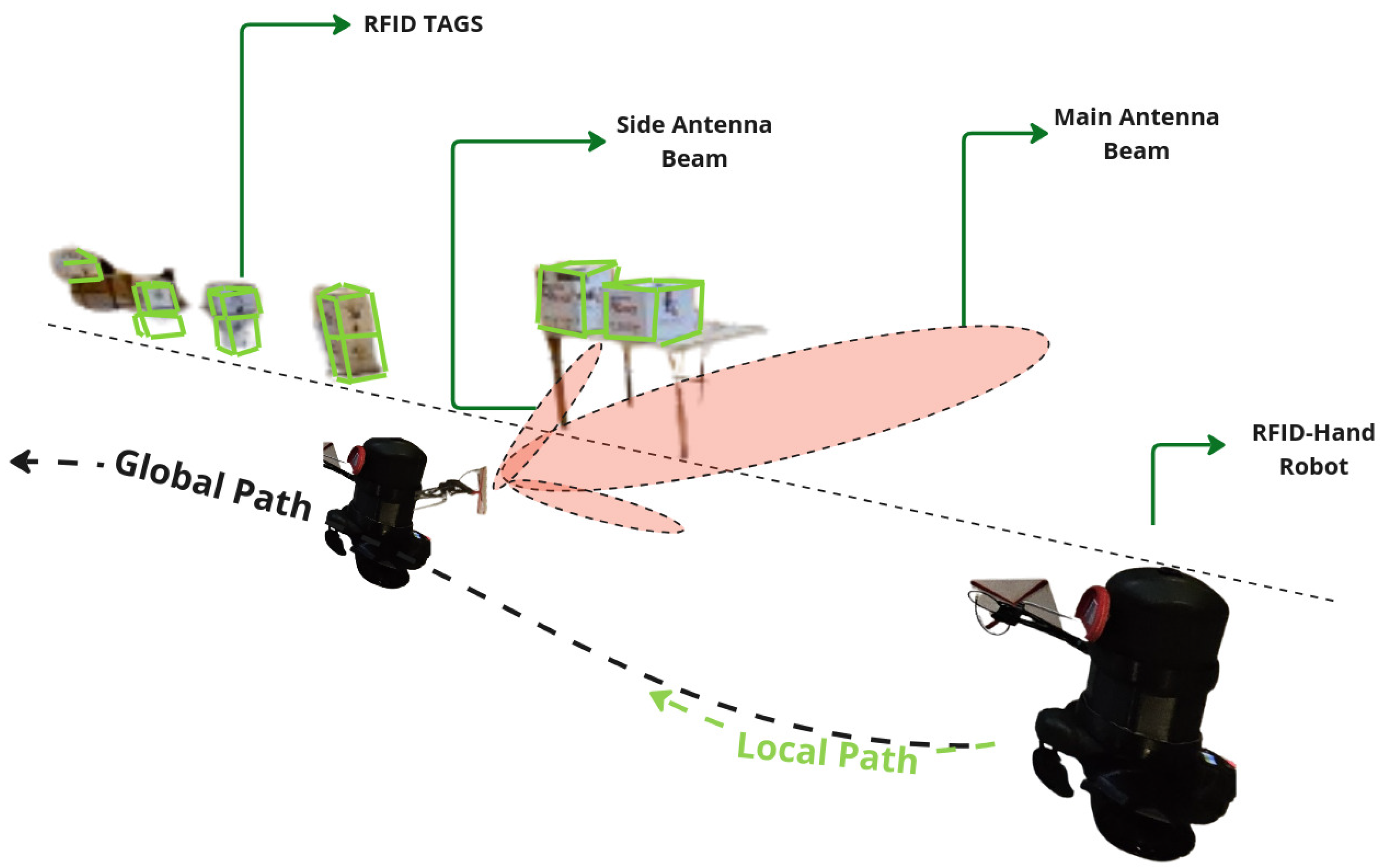
Figure 5.
A descriptive illustration of the RFID-HAND robot performing inventory with an articulated antenna.
Figure 5.
A descriptive illustration of the RFID-HAND robot performing inventory with an articulated antenna.

Figure 6.
A Graph of RFID tag readings from the robot with fixed antenna and articulated antenna experiments.
Figure 6.
A Graph of RFID tag readings from the robot with fixed antenna and articulated antenna experiments.

Figure 7.
A descriptive illustration of the RFID-HAND robot performing inventory with a fixed antenna.
Figure 7.
A descriptive illustration of the RFID-HAND robot performing inventory with a fixed antenna.
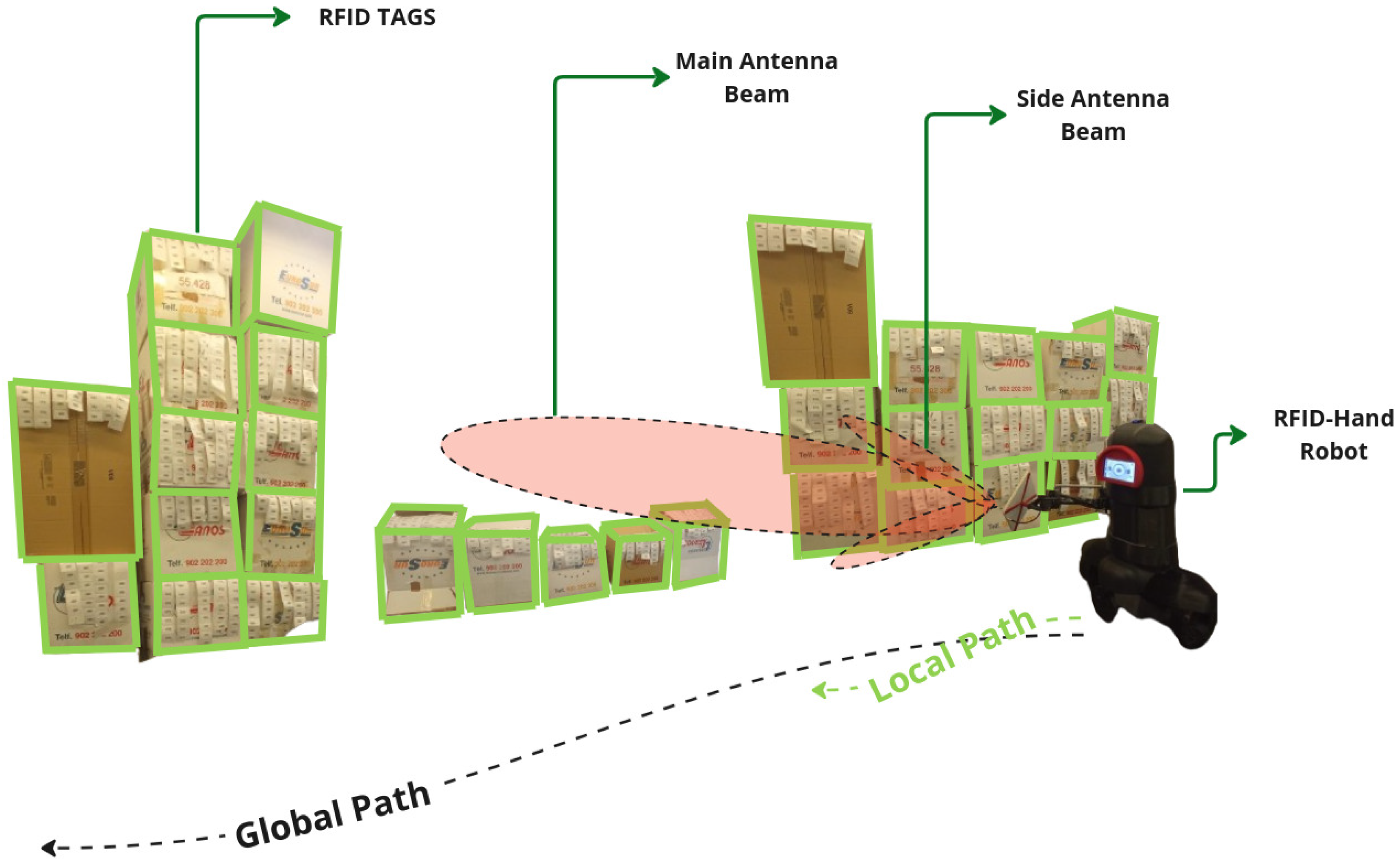
Figure 8.
A descriptive illustration of the RFID-HAND robot performing inventory with an articulated antenna.
Figure 8.
A descriptive illustration of the RFID-HAND robot performing inventory with an articulated antenna.
Disclaimer/Publisher’s Note: The statements, opinions and data contained in all publications are solely those of the individual author(s) and contributor(s) and not of MDPI and/or the editor(s). MDPI and/or the editor(s) disclaim responsibility for any injury to people or property resulting from any ideas, methods, instructions or products referred to in the content. |
© 2025 by the authors. Licensee MDPI, Basel, Switzerland. This article is an open access article distributed under the terms and conditions of the Creative Commons Attribution (CC BY) license (http://creativecommons.org/licenses/by/4.0/).
Copyright: This open access article is published under a Creative Commons CC BY 4.0 license, which permit the free download, distribution, and reuse, provided that the author and preprint are cited in any reuse.


