
Submitted:
21 January 2025
Posted:
22 January 2025
You are already at the latest version
Abstract
Robots are essential for carrying out tasks, for example, in a nuclear industry, where direct human involvement is limited. However, present-day nuclear robots are not versatile due to limited autonomy and higher costs. This research presents a teleoperated DexterTM nuclear robot’s transformation into an autonomous manipulator for nuclear sort and segregation tasks. The DexterTM system comprises a single/dual arm client manipulator designed to operate in extreme radiation environments and a similar single/dual arm local manipulator. In this paper, initially, a kinematic model and convex optimization based dynamic model identification of a single arm DexterTM manipulator is presented. This model is used for autonomous DexterTM control through Robot Operating System (ROS). A new integration framework incorporating vision, AI-based grasp generation and an intelligent radiological surveying method for enhancing the performance of autonomous DexterTM is presented. The efficacy of the framework is demonstrated on a mock-up nuclear waste test-bed using similar waste materials found in the nuclear industry. The experiments performed show potency, generality and applicability of the proposed framework in overcoming the entry barriers for autonomous systems in regulated domains like the nuclear industry and accelerate the adoption of automation without reinventing the wheel.
Keywords:
Nuclear Robot
; Sorting and Segregation
; Object detection
; Dynamics Identification
; Pick and Place
; Radiation detection
; Teleoperation
1. Introduction
Nuclear reactors are often preferred over fossil fuels for efficient and sustainable large-scale power generation without refueling for a long time. Developing nations worldwide consider nuclear energy as one of the important energy sources for meeting the growing energy demands [1]. Even though nuclear energy production contributes towards clean energy, disposal of nuclear wastes efficiently and safely is challenging[2]. In addition to that, efficient methods for decommissioning and clean-up of aging nuclear reactors, for example, Sellafield(UK) [3], and technology developments for handling nuclear disasters, for example, Fukushima (Japan) [4], are in need. The Nuclear Decommissioning Authority (NDA) oversees many legacy facilities in the UK that are in the process of being decommissioned and with rising nuclear wastes the scale of the problem is enormous [5]. Safe, effective and optimized waste management is a significant part of these long-term nuclear maintenance or decommissioning tasks. The radioactive wastes in nuclear power plants are commonly classified as High-Level Waste (HLW), Intermediate Level Waste (ILW), Low-Level Waste (LLW) and Very Low Level Waste (VLLW) according to the nature of material, level of radioactivity and the heat produced [6]. In order to facilitate a waste management strategy, these wastes needed to be sorted and segregated for optimal packing. Currently, these materials are handled by trained operators wearing personal protective equipment (PPE) [7] or by remotely controlled robots [8]. The human-led nuclear waste handling tasks are challenging due to proximity to radioactive wastes, limited efficiency, and high time consumption. In order to address these challenges, methodologies using robotic technologies have emerged to find ways to perform safe and efficient handling of nuclear materials.
Several attempts have been made earlier using robots [9,10,11,12], but robotic sorting and segregation of nuclear wastes are seldom reported in the literature. The Joint European Torus (JET) machine employs a human-in-loop approach for teleoperating the robotic boom and a dual-arm robotic system inside the JET Torus [13]. A robotic arm mounted on a mobile robot, Hydro-Lek, for nuclear decommissioning tasks is presented in [14,15]. Hydro-Lek is a seven degrees-of-freedom (DoF) hydraulic manipulator with a continuous jaw-rotation mechanism designed to grasp objects and cut ropes. The Oak Ridge National Laboratory’s Advanced Servomanipulator System and Dual-Arm Remote Sawing Manipulator System are task-specific robotic systems designed for specific nuclear decommissioning applications [16]. A modular robotic system for Reactor Core Detector Removal was presented in [17] for positioning, extracting, transporting, cutting, and coiling tasks. As robotics and artificial intelligence based computer vision technologies [18,19,20] have advanced through industrial automation, it is now clear that autonomous robotics can also play a key role in nuclear waste sort and segregation applications. [21,22] presented industrial non-nuclear waste sorting robotic methodologies using KUKA arms and a 4-DoF fast Parallel robot. Conventional robotic mechanisms and motion planning approaches work well for structured or semi-structured environments [23]. However, in harsh environment, the precarious nature of the physical tasks involved and regulatory constraints impose several other challenges in terms of deploying commercial robots for nuclear clean-up. A recent survey on challenges for future robotic sorters suggested the requirement for a highly dexterous dual-arm robotic systems for efficient sorting of unstructured and heap of objects [24]. Even though there is advancement in image-based detection of waste objects and environmental monitoring using computer vision and AI, developing a new autonomous dexterous robotic system specifically for sorting and segregation of nuclear waste is challenging.
Robotic remote operation technologies under human supervision are needed to perform hazardous decommissioning and sorting activities. For faster development and to overcome the entry barriers in a highly regulated nuclear domain, the authors solve the problem by building a novel solution to further automate and induce intelligence to the existing commercial DexterTM teleoperation system by Veolia Nuclear Solutions (VNS). A new methodology for switching from teleoperation to autonomous operation is presented based on rigorous system identification and dynamic modelling. This paradigm shift allows a quicker and more efficient introduction of shared autonomy into the previously manual tasks. The DexterTM manipulator comprises cable driven joints, complex gear assembly and parallel linkages. Identifying the dynamics of such a system is not straightforward and requires, precise modelling and system identifications. Dynamical model parameter identification of the DexterTM manipulator through excitation trajectories is one of the major contribution of this paper. The complex friction model and joint elasticity of cable-driven joints are also considered to obtain a comprehensive dynamic model through constrained optimization. This enables the DexterTM to perform sort and segregation tasks autonomously. The new framework presented realise object identification, classification, tracking, robotic grasping, sorting and packaging of nuclear wastes according to the radiation levels. For more complex grabs and tangled wastes, the integrated system would also have the ability to call on the expertise of a skilled operator to take over the task for manual operation; the remote DexterTM robot will replicate the operator’s movements on the local DexterTM. By sharing the tasks between human and computer intelligence, this approach offers a step change in safety and efficiency through limited intervention by operators for complex tasks. This methodology will enable accelerated adoption of automation and autonomy in extreme environments without rigorous changes in highly regulated sectors.
This paper first introduces the DexterTM robotic teleoperation system, and the sort and segregation experimental setup in Section II. In Section III, an outline of the proposed sort and segregation framework is presented. Section IV elaborates on the modeling, system identification, and control of the DexterTM for autonomous operation. The sensor integration and autonomous procedures for the radiation scanning, sorting, segregating, and packing of the wastes are described in Section V. Section VI covers experimental verification and validation, and finally, the concluding inferences are stated in Section VII.
2. Preliminaries and System Overview
This section presents relevant preliminary details that define the baseline architecture and building blocks of the new framework covered in Section III. Initially, the DexterTM, a commercial haptic-enabled and radiation-hardened teleoperated robotic platform, is introduced. Later, an overview of the experimental setup is provided, which accomplishes autonomous nuclear sort and segregation activities.
2.1. DexterTM teleoperation system
DexterTM, in Figure 1, is an exemplar of a collection of telemanipulation capabilities purposed for extremely hazardous environments, notably extreme radiation [13]. The DexterTM system is primarily developed for Human-in-Loop operations using kinematically identical local and remote arms, the former in a safe operations centre and the later in a hazardous operational environment. The Mascot (the predecessor to DexterTM) started life as an indispensable part of the Joint European Torus (JET) nuclear fusion program’s remote handling operation and it supports the nuclear fuel debris retrieval from a stricken reactor at the Fukushima Daiichi nuclear power plant in Japan. The capabilities of VNS’s DexterTM include a system that is able to repair, maintain and/or re-tool a larger complex mechanical system, including the ability to respond to unforeseeable upset conditions. In essence, this high-value system provides an insurance policy guaranteeing that the system can be kept in service despite not being accessible to humans. The human operator performs the tasks with the local manipulator, which the remote manipulator replicates in real-time in the remote location. The remote manipulator can be positioned up to from the local manipulator using only data cables and there is no mechanical connection between the two systems. One of the key feature of the DexterTM arm is that the arm can be considered as a straightforward replication of the operator’s arms. The human operator can prepare for tasks and carry them out almost exactly as if they were intervening in the environment directly. Along with the extreme smoothness, responsiveness, and sensitive force feedback of the arms coupled with camera feedback creates a sense of “Telexistence” for the operator.
A single arm of DexterTM system comprises all revolute joints to exhibit 6-DoF motion. The first three joints are driven by a gear system and last three joints are cable driven in addition to cable driven two finger end-effector. The electrical actuators responsible for each joint motions are placed together at the base of the DexterTM in a specialised configuration with in a protective casing. This is beneficial for reliable operations in a nuclear environment where radiations and high temperatures will effect the electrical systems. In order to achieve heavy load carrying capacity, a specialised parallelogram mechanism is also provided between joint one and three. For transforming this torque controlled DexterTM teleoperation system to autonomous system, where currently the remote arm joint positions follow local arm joint positions, an accurate kinematic and dynamical model has to be obtained. The dynamical model identification of DexterTM robot is challenging considering the above mentioned configurations and specialised actuation mechanisms. Further, the frictions in joints and the elasticity of cables bring additional challenges in model identification.
2.2. Sort and Segregation Experimental Setup Overview
The experimental setup comprising DexterTM local and remote arms is shown in Figure 2(a). The remote system is isolated to perform complete sort and segregation operations safely similar to a nuclear environment. As shown in Figure 2b, sensors and sorting tables are placed within the worspace of remote arm for performing autonomous operations. In order to obtain the 3D information of the object, two industrial grade SICK sensors are placed facing towards the robot workspace in an eye-to-hand configuration. Initially, the sorting table is loaded with all the waste objects that need sorting. Once a waste object is picked up and its characteristics identified, it will be deposited in ILW, LLW, or recycling trays, as shown in Figure 2(b). Since the robot base is stationary, a trolley mechanism manually moves the corresponding trays into the robot’s workspace after characterizing the waste item.
3. Outline of Proposed Framework
The new framework presented in this paper aims to advance the autonomy and automation of DexterTM system and integrate it with advanced characterization and tracking technologies to identify, classify, transfer and package waste items commonly found in the nuclear industry. Figure 3 shows a top-level system process flow for a nuclear sort-and-segregation task using the DexterTM system, which comprises various control modules, as shown in Figure 4. The low level control module consists of DexterTM kinematic and derived dynamic models, and position controllers. Using ROS framework, various submodules and Task Groups (TG) are interconnected for task transitions, sensor interfaces, safety, teleoperation and Digital Twin in the middle-level control. The GUI enables an interface to control various control tasks in middle-level control and also act as an information display system for the operator to make decisions. The system is designed such that high priority is given for system and operation safety of robot through process control. The process control is also responsible for identification of various failure modes, such as object slip and drop, and failure to generate feasible trajectory to desired pose. The failure modes will generate corresponding flags in the GUI for the operator to intervene and take necessary actions.
4. Robot Modelling, Identification and Control
This section initially describes DexterTM’s kinematic model and an analytical formulation of dynamic equations, including friction and joint elasticity components. Next, a system identification procedure is presented for obtaining reliable dynamic parameters. Finally, a joint space position controller is implemented using a pre-computed feed-forward torque controller.
An open kinematic chain of DexterTM joint frames, shown in of Figure 5, is considered for obtaining the minimal kinematic model of the robot. The calculated Denavit–Hartenberg (DH) notation based kinematic parameterization of the DexterTM is provided in Table 1, where , and are corresponding link length, offsets and joint angles of DexterTM as shown in Figure 5.
4.1. DexterTM Kinematic and Dynamic Model
The motion of the 6-DoF DexterTM manipulator can be described by the general rigid body dynamics as in (1)
where , , , represent the joint position, velocity, and acceleration vectors respectively. represent the mass/inertia matrix containing respective mass and inertia tensors . matrix contains corresponding Coriolis and Centrifugal forces/torques. The terms and are the gravitational force and input torque vectors respectively. In order to incorporate the dynamical effects due to friction and joint elasticity of DexterTM mechanisms, two additional terms and are incorporated into the dynamical model. The joint friction term is modeled as
where , , , and represents static, viscous, Coulomb and Striebeck constants respectively [25]. Similarly, the elasticity of the joints are modeled as
where is a diagonal stiffness matrix.
The identification of constant dynamical parameters for the DexterTM includes additional terms from the friction and elasticity models. These additional parameters are required for the accurate position of DexterTM through torque control, considering the complex gear systems and cable-driven actuation methods.
4.2. Dynamic Model Parameter Identification
The Dynamical parameter identification [26] is a crucial part in the process of transforming purely teleoperated DexterTM robot to an autonomous system. The direct identification of model parameters are not straightforward considering the advanced DexterTM robot mechanisms. Therefore, data collected by actuating the DexterTM manipulator using excitation trajectories are used to identify the dynamical model parameters through convex optimization. An outline of the parameter identification procedure is shown in Figure 6. From the generic dynamic model of the DexterTM robot (1), the unknown parameters that needs to be identified for link are mass , Center-of-Mass (CoM) , inertia parameters (), friction constants () and stiffness constant . In total 84 parameters need to be identified for a 6-DoF DexterTM manipulator.
For simplicity, (1) is represented in the linear form [27] by
where represents a regression matrix and represents the unknown dynamic parameters vector. From the DexterTM robot’s physical configuration its understandable that not all dynamical parameters will contribute to the dynamic model and becomes zero. Hence, a minimum set of identifiable parameters is obtained from (4) using numerical QR decomposition method [28]. The dynamic equation with reduced number of parameters () can be represented as
where and are reduced regression matrix and vector of identifiable dynamic parameter set. From an excitation trajectory , where time step, and using the collected joint position, velocity, acceleration and torque values, the linear equation in (5) can be represented as
where is an extended regression matrix
4.2.1. Identification by Minimization
The dynamical parameter estimation is posed as a minimization problem between measured torque vector and predicted torque vector in (6) using an excitation trajectory. The parameter identification is performed by solving the following constrained optimization problem
where represents the constraints and denotes search space. In order to obtain a physically feasible parameter set following physical consistency constraints, , are defined.
- The mass of the links must be positive definite: ,
- The inertia tensors must be positive definite ,
- Eigenvalues of the inertia tensors () must satisfy triangle inequality conditions , as in [29],
- The mass center should remain in its convex hull that is and [30], where and represents lower and upper bounds of the respectively,
- The stiffness of the spring is positive definite:
4.2.2. Optimal Excitation Trajectory Generation
It is important to ensure that the excitation trajectories provided to the DexterTM must induce all the modeled dynamical effects for accurate parameter identification. Therefore, finite Fourier Series based excitation trajectories are used to obtain variable amplitudes and frequencies. Using Fourier Series functions the angular position trajectories of joint can be written as
where , N and are frequency, the number of the harmonics and initial joint angles respectively. and are trigonometric term constants and parameters have to be identified per joint. Since the joint angle’s range and workspace of DexterTM manipulator is limited, another constrained nonlinear optimization is performed in order to generate sufficiently rich trajectories. Minimizing the condition number of the regression matrix [31] is defined as an objective function towards this with joint and pose constraints:
where represent task space end-effector positions.
4.3. Position Control System Design of DexterTM
Advanced control methods are required for highly non-linear robots like DexterTM for accurate and efficient trajectory execution. The computed torque control method with linearization for compensating the robot dynamics is one of the common nonlinear control methods [32]. Instead of altering the DexterTM’s internal low-level torque control architectures, an offline calculated feed-forward computed torque controller is utilized in this research.
Based on the desired joint trajectories (), predicted joints torques are obtained offline using (1). The controller then applies these predicted joints torques to DexterTM joints together with a Proportional–Integral–Derivative (PID) control as shown in Figure 7. The joint control command for the DexterTM system can be written as:
where joint error is defined as and are PID gains.
4.4. Motion Planning and Trajectory Generation
For generating optimal motion trajectories on DexterTM robot in-order to reach desired positions, Open Motion Planning Library’s (OMPL’s) Rapidly Exploring Random Tree (RRT*) algorithm is utilised through ROS [33]. The implemented motion planner considers joint limits, singularities and self-collisions of DexterTM manipulator. In order to avoid collisions with objects in the DexterTM workspace, a 3D occupancy grid map (Octomap) of the environment is also generated and included in the planner. The real-time point cloud input of the environment is obtained from depth cameras. Figure 8 presents the point cloud of the environment generated on the test setup described in Section II(B) for optimal trajectory generation with collision avoidance.
5. Autonomous Object Grasping and Packing
Autonomous detection of objects from a pile, its characterisation and packing using a robotic system requires efficient algorithms and their integration into a single framework. The autonomous framework developed in this research (Figure 3) around DexterTM system utilizes various AI based methodologies to perform nuclear sort and segregation tasks in a single pipeline. The methodologies used for identifying the objects, how and where to grasp the objects, material characterisation, radiation scanning of the objects and optimal packing are presented in this section.
5.1. Object Detection, Material Characterization and Grasp Point Generation
The vision system of the autonomous DexterTM consists of two stationary SICK Visionary-S RGBD sensors attached to the sensor frames as shown in Figure 2(b). These industrial sensors are traditionally used for verifying box packing and are ideal for identifying a large number of items simultaneously with high frequency of operation. Two SICK sensors are carefully placed in the DexterTM workspace such that a single point cloud of the whole scene can be generated from two RGBD images, which almost completely describes the scene in 3D. The next step in object detection and classification involves using efficient AI-based image processing algorithms.
In order to improve performance and to avoid integration complexities in terms of system requirements and dependencies, segmentation, classification and material characterization is implemented together using the SoftGroup [34] AI model. The 3D instance segmentation model, SoftGroup, also provided the flexibility for isolating point cloud of the target object from the robot gripper to perform efficient single object characterization rather than only from piles. Around 130 different objects commonly seen in nuclear waste sites were considered, and over 400 scans of these objects were carried out to formulate the training dataset for the SoftGroup model. Each scan was created by both SICK cameras taking an RGBD image simultaneously, which was then processed into a single point cloud of the whole scene. Along with the scans from a pile of objects on the sorting table, objects held by DexterTM above the sorting table were also collected at different orientations. In the preprocessing stage, ground truth segmentation masks and classification tags consisting of object category, material, mass, volume and density were manually annotated. For material categorisation of the objects, the object category and material classifications are merged to encode both geometric/semantic and material information. For example, instead of having “steel” and “aluminium” as material classes and “rod” and “metal scrap” as category classes, “steel rod”, “steel scrap”, “aluminium rod” and “aluminium scrap” are considered as separate independent classes. In this way, a single SoftGroup model performs all segmentation and classification tasks for the whole system, significantly reducing the system’s complexity and running time, without sacrificing the model’s prediction accuracy.
Once the objects in the pile are detected and identified, the next step is to identify feasible grasp poses [35] on the objects in order to perform grasping by the DexterTM. An object grasp pose generator pipeline is developed using Contact-GraspNet [36], which takes the segmented and classified point cloud as input.
5.2. Geometry Characterisation and Mass Estimation
Objects’ geometric information, such as length, width, height, surface area, and volume, is another important characteristic required for optimal packing. This information is crucial, along with the object type and name in nuclear applications for keeping a catalog of objects in a packed container, especially if radioactive. The geometric characterisation is performed on objects in a pile and also after the objects held by the gripper for revalidation. A sequence of operations is performed using the point cloud generated by two cameras, which outputs a watertight mesh of the object under consideration for geometric characterisation. Generally, with two RGBD cameras, the complete capture of all the sides of the object is not possible, and the corresponding mesh is unreliable for accurate characterisation. In the first step, the combined 3D point cloud obtained from two cameras is down sampled and an interpolation is performed to fill the vacant space on the object point cloud. Next, a simple mesh (dense 3D geometry) is created from the interpolated point cloud using a surface reconstruction method called Ball pivoting using Open3D [37]. In order to calculate the volume of objects, a watertight mesh consisting of a continuous and closed surface is needed. Using the manifold method in Open3d, the watertight meshes are generated, and finally, the geometric information of the object is obtained.
On top of identifying the object mass from camera input, a direct mass estimation model using DexterTMrobot is also developed for better accuracy. For this, 25 different objects with known masses and the torque value of DexterTM joint-1 to lift the object are considered. After the object is grasped, the DexterTM is moved to a specific predefined configuration to estimate the mass. Using the ground truth mass and corresponding torque values, a fourth-order function is fitted using the linear least square curve fitting method Figure 9. Using this mapping, the object’s mass m is obtained using the following function:
where is the corresponding measured torque values to lift the object.
5.3. Radiological Surveying and Decision
In a nuclear sort and segregation application, one of the crucial tasks is the efficient detection of object’s radioactivity levels. In this research, real radioactive objects were not available for testing and therefore a radiological surveying pipeline is designed where random activity levels are assigned to segmented items in the point cloud and radiation measurements are simulated on a mock up radiation detector held by the DexterTM robot. For performing radiation scanning, a 2D end-effector trajectory is generated at a fixed height from the tray where objects that need to be picked are placed. Although the trajectory planner aims to scan the whole tray, it is focused more on the object location inputs from the point cloud and segmentation outputs to reduce scan time requirements. The DexterTM performs slow and detailed scanning movements near the objects and finally, if calculated confidence for waste sentencing is low, random scanning is performed over the tray in order to obtain a more accurate object activity result.
The radiation detector demonstrated here is Createc’s N-Visage Recon. As this is a gamma detector, the alpha and beta content of waste items is determined though application of radionuclide fingerprints in this example. Use of an alpha/beta monitor was explored and the positional accuracy of the DexterTM demonstrated surface monitoring with this type of monitor to be possible for simple flat surfaces though challenging for more complex surfaces. The output activity for each waste item is obtained through calculation in Createc’s N-Visage algorithm [38], where measurement uncertainty and Minimum Detectable Activity (MDA) is determined through a Monte Carlo based random sampling method in the algorithm and application of the Currie Equation [39]. For sorting the object into one of the ILW, LLW, or recycling trays by the DexterTM, this activity model is used.
5.4. Bin Packing
Efficient bin packing is another challenge that is faced in the nuclear industry. The strategy of dropping objects randomly into the bin often results in instability of heterogeneous objects inside the bin, uneven weight distribution and inefficient space utilization. An efficient container packing algorithm, Tetris, is utilized for autonomous bin packing using DexterTM robot[40]. The algorithm calculates the quasi-optimal position and orientation to place the picked objects in the destination container. Initially, using the 2D Tetris algorithm the bottom layer of the bin is filled using a target function such that it minimizes the total unoccupied bottom surface area of the container. The target function places the objects as close as possible to this bottom wall and also minimize the holes in the bottom surface area of the container. Next, based on the shape of the object in hand and the landscape of the existing objects in the container, another target function executes Tetris in the z-direction and tries to maximize the number of objects packed and simultaneously minimize the gap volume of the container. With this target function, it would try to put each object onto the lowest region as possible in the container, but in the meantime, also try to minimise the void volume underneath the object that would be created after putting it, as this volume would not be recovered.
6. Experimental Evaluation
This section presents the experimental evaluation of the proposed sort-and-segregation framework, outlined in Section III, using DexterTM manipulator. The experimental setup with cameras and sorting tables is shown in Figure 2. The initial part of this section presents the results of DexterTM dynamical model parameter identification. For verifying its effectiveness, the tracking performance is studied by implementing a position controller. Next, the results of sort and segregation subsystems, presented in Section V, are provided. Finally, the integrated system performance is evaluated through successful nuclear sort-and-segregation experiments on similar objects from the nuclear industry.
6.1. Parameter Identification and Model Validation
The input excitation trajectories for dynamical model parameter identification of the DexterTM manipulator are generated by solving (10) using convex optimization, as explained in Section IV(B). The generated reference trajectories induces the modeled dynamical effects, friction and elasticity, of the DexterTM manipulator. The corresponding joint positions are shown in Figure 10.
Using these reference trajectories, the DexterTM joints are actuated using the position controller shown in Figure 7 where an approximate of dynamical parameters were used from DexterTM CAD model. In order to find the exact dynamical model parameters, initially, the executed joint torques and angular motion information () are collected and stacked across each time step as the training data set. Using this data, a suitable set of dynamic parameters is estimated through convex optimization using (8). The designed position controller (11) is tested along with the updated dynamical parameters to accomplish DexterTM autonomous control as shown in Figure 11. Although there are minimal deviations during the motion due to the nonlinearity caused by its cable-driven nature and the unmodeled dynamic effects, the controller showed good performance that enabled the desired target to be achieved.
Table 2 compares the torque tracking error and their deviation for all joints for the generated training and test trajectory. Even though joint-2 and joint-3 errors are slightly higher, overall percentage error and standard deviations are minimal, resulting in less than end-effector mean positional error through the feed-forward nonlinear control. These results confirm the accuracy of the dynamical model parameters identified.
6.2. Sort and Segregation Subsystems
The results of sort and segregation operation performed using experimental setup, explained in Section II(B), in a real environment are provided below. Integrating individual subsystems led to expected full system performance, which successfully sorted and segregated various objects from a heap.
6.2.1. 3D Instant Segmentation and Classification
The pipe-line for sort and segregation process starts by generating two point clouds of the environment using two SICK sensors. Initially, the two point clouds were processed into a single point cloud of the whole scene using conventional Multiview Stereo (MVS) reconstruction method [41] and performed a denoising. The denoising is required to overcome the intrinsic device limitation of the SICK sensors, especially when measuring highly reflective surfaces. The developed SoftGroup model takes the combined point cloud input and performed segmentation and classification of each object agnostically from the pile and object in Dexter’s hand. An example of such a pair of acquired RGB-D images for a scene, merged single point cloud and the result of the SoftGroup model-based pipeline are shown in Figure 12. It can be seen that most objects were cleanly segmented, and the safety hat in the gripper was correctly classified (other objects were also classified by the model but not illustrated in the figure for brevity). A second level of object classification, while DexterTM holds the object and rotates it to three predefined orientations, is also performed by extracting its isolated point cloud. The SoftGroup model predicts the probabilistic vector of the target object belonging to each candidate category. The pipeline then reports the most likely category of the target object as the category with the highest probability averaged across the predictions. The target object’s point cloud was extracted from each scan orientation’s using the segmentation mask predicted by the SoftGroup model, and then merged together to obtain a complete point cloud of the object. Figure 13 shows the complete extracted point cloud of a safety hat, and also the overall categorical probability histogram of it as averaged across the detailed scans’ model predictions. A sample of the objects used and their category are provided in Table 3.
6.2.2. Radialogical Surveying
After scanning the pile and detecting objects, radiological surveying is conducted. Initially, DexterTM grasps the radiation detector and performs the scanning operation according to the scanning trajectory calculated offline. The radiation scanning trajectory is generated based on the segmented object positions in the point cloud of the pile. Figure 14 demonstrates the generated end-effector trajectories, which perform slow scanning near objects and a final random scanning if confidence in radiation measurement and subsequent waste sentencing route is determined to be low. In the absence of real radioactive waste items, random radioactivity levels are assigned to objects for the experiments conducted. In experiments, the implemented model creates simulated detector measurements and uses these to create a radioactivity map superimposed on the point cloud while the trajectory is being executed. Item radiation activity is then matched with associated detected objects. The video (https://youtu.be/v2hlDxKDGcM) demonstrates a radiation-scanning experiment post object detection.
6.2.3. Grasp Pose Generation
The core grasp-pose candidate generation method used in this research is Graspnet (Section 5.1). On top of Graspnet, a heuristic system is implemented on the generated grasp candidates to create higher quality and deterministic/reproducible grasp poses in cluttered piles and extreme cases such as the small lego block. This grasp generation system prioritizes grasp poses of the targeting objects having larger top surface areas and higher up in a pile. This strategy helped to pick the objects without much disturbance to the pile and identify objects that were hidden in the previous scan. It also prioritizes grasp poses closer to the geometric centre of each object, as such grasp poses would lead to a lower chance for the object to rotate, tip over, or slip out from the gripper during grasping and after being picked up. Figure 15 shows the top 3 highest priority grasp poses generated by the algorithm for two different clutter piles.
6.2.4. Object Characterisation
The pipeline for object geometry and physical characterization was based on conversion of point cloud of the object into a watertight mesh body, as explained in Section 5.2. Figure 16 shows two examples of the extracted point clouds for a wellington boot on the table and a Plastic hose held by DexterTM. By using Open3D’s inbuilt functionality, approximate geometric information of the object from the watertight mesh is obtained. On comparing the accuracy against the ground truth manual measurements of over 50 objects, closer results were observed except for objects with complex shapes, in particular, those with internal hollowness or folded structures. The estimated masses of objects were calculated using the estimated volume of object from Open3D, the estimated object material from category classification and the object category density values. In addition, an estimated mass of the object held by the DexterTM gripper is also calculated based on the torque feedback of the motors. The torque-based measurements were more closer to the mass of ground truth objects. Hence, the vision-based mass information is used as a redundant information for second validation.
6.3. Bin Packing
Four different types of “human benchmarks” packing algorithms are analysed and tested in simulation to validate the efficacy of the developed Tetris algorithm. The benchmarks are 1) Center Algorithm: randomly oriented object dropped at the center of the container, 2) Random Algorithm: randomly oriented object dropped at a random position of the container, 3) Lower Bound Algorithm [42], and 4) Orthogonal Low algorithm [43]. Each algorithm runs ten times for the same pile of objects. Table 4 presents the average values of the performance of the algorithms for comparison.
The unoccupied volume (voidage) of the container is used as a scoring method for comparison and is calculated as the volume of voidage = volume of container - the total volume of objects. The packed container volume in the experiments is . Although the Tetris algorithm is slower than the other algorithms, the optimal packing with the minimum voidage rate is achieved. The result of bin packing using the developed Tetris algorithm in a real experiment is shown in Figure 17. In this experiment, a total of 40 items are placed into the container with a total volume of and voidage . A container voidage is obtained in this experiment with an average pose generation run time of .
6.4. Full System Demonstration
The designed sort and segregation subsystems and the DexterTM control systems are integrated into a full system demonstrator, as shown in Figure 18. It consists of a DexterTM manipulator, two SICK Visionary-S cameras, one sorting tray, LLW, ILW, and recyclable trays. The full system provides a continuous sequential operation of sub-tasks, as shown in Figure 19. The examples provided in Figure 19 show the complete execution of the integrated system, from picking to dropping for various objects.
Multiple experiments are performed and the efficacy of the developed system and framework was observed through successful sorting and segregation of the objects used. The result showcases the successful and efficient segregation of objects into LLW, ILW, and recyclable trays. The database created contains the objects utilized, their properties and parameters Table 5) and a summary of each container (Table 6). The video (https://youtu.be/iIb8am8WkWs) presents a complete sort and segregation system demonstration for a pile of objects. The video shows that the designed system can successfully sort and segregate nuclear waste. It is also shown in the video that the process is completed by switching to teleoperation mode as a result of the manipulation error due to a huge object in the pile that cannot get into the scanning position.
7. Conclusion
Efficient and scalable robotic methodologies are required to overcome the entry barriers for autonomous systems in challenging environments like the nuclear industry. An autonomous robotic sort and segregation framework for nuclear waster handling was presented by introducing autonomy into DexterTM, a purely teleoperated nuclear robot. The framework relies on dynamical model parameter identification of DexterTM through Fourier series based excitation trajectories for autonomous operations and integration of methodologies for object identification, classification, characterisation and radiological surveying through ROS. For more complex grabs and tangled waste, the integrated system can call on the expertise of a skilled operator to take over the task through teleoperation. The effectiveness of this framework was verified by performing several sort and segregation operations safely on a mock-up nuclear waste test-bed using similar waste materials found in the nuclear industry. A new database of the objects packed into different bins and their properties is also generated and catalogued for future referencing. The results presented in this paper show a paradigm shift in enabling the adoption of autonomy in addition to automation in the regulated sectors.
Author Contributions
Conceptualization: Mini Rai, Amir G Esfahani, Marc Hanheide and Mike Moulin-Ramsden; Control methodology and software development: Mithun Poozhiyil, Omer F Argin and Ryan King; Image processing software and Integration: Mithun Poozhiyil, Wen Yang, Laura Palacio Garc´ıa; GUI: Iain Mackay, Sho Okamoto and Kelvin Yeung; Radiological surveying methodology: Ross Fawkes, Writing—original draft preparation: Mithun Poozhiyil and Omer F Argin; Review and Editing: Mini Rai; Funding acquisition and project administration and supervision: Mini Rai, Amir G Esfahani, Marc Hanheide, Phil Saunderson, Mike Moulin-Ramsden and Abhishek Mishra; All authors have read and agreed to the published version of the manuscript.
Funding
This research was funded by Innovate UK SBRI Competition - Sort and Segregate Nuclear Waste (Project Id. 10014065)
Conflicts of Interest
The authors declare no conflicts of interest. The funders had no role in the design of the study; in the collection, analyses, or interpretation of data; in the writing of the manuscript; or in the decision to publish the results.
Abbreviations
The following abbreviations are used in this manuscript:
| ROS | Robot Operating System |
| AI | Artificial Intelligence |
| NDA | Nuclear Decommissioning Authority |
| UK | United Kingdom |
| NDA | uclear Decommissioning Authority |
| HLW | High-Level Waste |
| ILW | Intermediate-Level Waste |
| LLW | Low-Level Waste |
| VLLW | Very Low-Level Waste |
| JET | Joint European Torus |
| DoF | Degrees-of-Freedom |
| VNS | Veolia Nuclear Solutions |
| TG | Task Group |
| GUI | Graphical User Interface |
| DH | Denavit–Hartenberg |
| PID | Proportional–Integral–Derivative |
| RRT | Rapidly Exploring Random Tree |
| MDA | Minimum Detectable Activity |
| CAD | Computer Aided Design |
| MVS | l Multi-View Stereo |
| OMPL | Open Motion Planning Library |
| PPE | Personal Protective Equipment |
References
- Yuldashev, N.; Saidov, M. The Economy of the Countries of the World is Experiencing the Need for Nuclear Power Plants. American Journal of Economics and Business Management 2023, 6, 86–99. [Google Scholar]
- Deng, D.; Zhang, L.; Dong, M.; Samuel, R.E.; Ofori-Boadu, A.; Lamssali, M. Radioactive waste: A review. Water Environment Research 2020, 92, 1818–1825. [Google Scholar] [CrossRef]
- Baldwin, N. Remediating Sellafield: A New Focus for the Site. In Proceedings of the International Conference on Radioactive Waste Management and Environmental Remediation; 2003; Vol. 37327, pp. 35–40. [Google Scholar]
- Nagatani, K.; Kiribayashi, S.; Okada, Y.; Otake, K.; Yoshida, K.; Tadokoro, S.; Nishimura, T.; Yoshida, T.; Koyanagi, E.; Fukushima, M.; et al. Emergency response to the nuclear accident at the Fukushima Daiichi Nuclear Power Plants using mobile rescue robots. Journal of Field Robotics 2013, 30, 44–63. [Google Scholar] [CrossRef]
- NDA. UK Radioactive Waste Inventory. https://ukinventory.nda.gov.uk/[Last Accessed: 31 Jan 2024].
- NDA. Integrated Waste Strategy. https://assets.publishing.service.gov.uk/government/uploads/system/uploads/attachment_data/file/838828/Radioactive_Waste_Strategy_September_2019.pdf/[Last Accessed: 31 Jan 2024].
- Teunckens, L.; Walthéry, R.; Lewandowski, P.; Millen, D.; Baumann, S. Individual Protection Equipment and Ergonomics Associated with Dismantling Operations in a Hostile Environment. In Proceedings of the International Conference on Radioactive Waste Management and Environmental Remediation. American Society of Mechanical Engineers; 2001; Vol. 80166, pp. 583–587. [Google Scholar]
- Tokatli, O.; Das, P.; Nath, R.; Pangione, L.; Altobelli, A.; Burroughes, G.; Jonasson, E.T.; Turner, M.F.; Skilton, R. Robot-assisted glovebox teleoperation for nuclear industry. Robotics 2021, 10, 85. [Google Scholar] [CrossRef]
- Buckingham, R.; Graham, A. Dexterous manipulators for nuclear inspection and maintenance—case study. In Proceedings of the 2010 1st International Conference on Applied Robotics for the Power Industry. IEEE, Montreal, QC, Canada; 2010; pp. 1–6. [Google Scholar]
- Iqbal, J.; Tahir, A.M.; ul Islam, R.; et al. Robotics for nuclear power plants—challenges and future perspectives. In Proceedings of the 2012 2nd international conference on applied robotics for the power industry (CARPI). IEEE, Zurich, Switzerland; 2012; pp. 151–156. [Google Scholar]
- Kim, C.h.; Seo, Y.c.; Lee, S.u.; Choi, B.s.; Moon, J.k. Design of a heavy-duty manipulator for dismantling of a nuclear power plant. In Proceedings of the 2015 15th International Conference on Control, Automation and Systems (ICCAS). IEEE, Busan, Korea (South); 2015; pp. 1154–1158. [Google Scholar]
- Tsitsimpelis, I.; Taylor, C.J.; Lennox, B.; Joyce, M.J. A review of ground-based robotic systems for the characterization of nuclear environments. Progress in nuclear energy 2019, 111, 109–124. [Google Scholar] [CrossRef]
- Sanders, S. Remote operations for fusion using teleoperation. Industrial Robot the international journal of robotics research and application 2006, 33, 174–177. [Google Scholar] [CrossRef]
- Bakari, M.J.; Zied, K.M.; Seward, D.W. Development of a multi-arm mobile robot for nuclear decommissioning tasks. International Journal of Advanced Robotic Systems 2007, 4, 387–406. [Google Scholar] [CrossRef]
- Montazeri, A.; Ekotuyo, J. Development of dynamic model of a 7DOF hydraulically actuated tele-operated robot for decommissioning applications. In Proceedings of the 2016 American control conference (ACC). IEEE, Boston, MA, USA; 2016; pp. 1209–1214. [Google Scholar]
- Trevelyan, J.; Hamel, W.R.; Kang, S.C. Robotics in hazardous applications. Springer handbook of robotics 2016, pp. 1521–1548.
- Han, Z.; Tian, H.; Meng, F.; Wen, H.; Ma, R.; Duan, X.; Zhang, Y.; Liu, C. Design and experimental validation of a robotic system for reactor core detector removal. In Proceedings of the 2021 IEEE International Conference on Robotics and Automation (ICRA). IEEE, Xi’an China; 2021; pp. 2473–2479. [Google Scholar]
- Lu, W.; Chen, J. Computer vision for solid waste sorting: A critical review of academic research. Waste Management 2022, 142, 1023–1040. [Google Scholar] [CrossRef]
- Bohg, J.; Morales, A.; Asfour, T.; Kragic, D. Data-driven grasp synthesis—a survey. IEEE Transactions on robotics 2013, 30, 289–309. [Google Scholar] [CrossRef]
- Xie, C.; Xiang, Y.; Mousavian, A.; Fox, D. Unseen object instance segmentation for robotic environments. IEEE Transactions on Robotics 2021, 37, 1343–1359. [Google Scholar] [CrossRef]
- Kiyokawa, T.; Katayama, H.; Tatsuta, Y.; Takamatsu, J.; Ogasawara, T. Robotic waste sorter with agile manipulation and quickly trainable detector. IEEE Access 2021, 9, 124616–124631. [Google Scholar] [CrossRef]
- Leveziel, M.; Laurent, G.J.; Haouas, W.; Gauthier, M.; Dahmouche, R. A 4-DoF parallel robot with a built-in gripper for waste sorting. IEEE Robotics and Automation Letters 2022, 7, 9834–9841. [Google Scholar] [CrossRef]
- Pan, Z.; Zeng, A.; Li, Y.; Yu, J.; Hauser, K. Algorithms and systems for manipulating multiple objects. IEEE Transactions on Robotics 2022, 39, 2–20. [Google Scholar] [CrossRef]
- Kiyokawa, T.; Takamatsu, J.; Koyanaka, S. Challenges for Future Robotic Sorters of Mixed Industrial Waste: A Survey. IEEE Transactions on Automation Science and Engineering 2022, 21, 29–43. [Google Scholar] [CrossRef]
- Armstrong-Hélouvry, B.; Dupont, P.; De Wit, C.C. A survey of models, analysis tools and compensation methods for the control of machines with friction. Automatica 1994, 30, 1083–1138. [Google Scholar] [CrossRef]
- Han, Y.; Wu, J.; Liu, C.; Xiong, Z. An iterative approach for accurate dynamic model identification of industrial robots. IEEE Transactions on Robotics 2020, 36, 1577–1594. [Google Scholar] [CrossRef]
- Siciliano, B.; Sciavicco, L.; Villani, L.; Oriolo, G. Robotics: Modelling, Planning and Control; Springer-Verlag: New York, NY, USA, 2009. [Google Scholar]
- Gautier, M. Numerical calculation of the base inertial parameters of robots. Journal of robotic systems 1991, 8, 485–506. [Google Scholar] [CrossRef]
- Gaz, C.; Cognetti, M.; Oliva, A.; Giordano, P.R.; De Luca, A. Dynamic identification of the franka emika panda robot with retrieval of feasible parameters using penalty-based optimization. IEEE Robotics and Automation Letters 2019, 4, 4147–4154. [Google Scholar] [CrossRef]
- Sousa, C.D.; Cortesao, R. Physical feasibility of robot base inertial parameter identification: A linear matrix inequality approach. The International Journal of Robotics Research 2014, 33, 931–944. [Google Scholar] [CrossRef]
- Argin, O.F.; Bayraktaroglu, Z.Y. Consistent dynamic model identification of the Stäubli RX-160 industrial robot using convex optimization method. Journal of Mechanical Science and Technology 2021, 35, 2185–2195. [Google Scholar] [CrossRef]
- Khalil, W.; Dombre, E. Modeling identification and control of robots; CRC Press, 2002.
- Sucan, I.A.; Moll, M.; Kavraki, L.E. The open motion planning library. IEEE Robotics & Automation Magazine 2012, 19, 72–82. [Google Scholar]
- Vu, T.; Kim, K.; Luu, T.M.; Nguyen, T.; Yoo, C.D. Softgroup for 3d instance segmentation on point clouds. In Proceedings of the Proceedings of the IEEE/CVF Conference on Computer Vision and Pattern Recognition; New Orleans, Louisiana, 2022; pp. 2708–2717. [Google Scholar]
- Newbury, R.; Gu, M.; Chumbley, L.; Mousavian, A.; Eppner, C.; Leitner, J.; Bohg, J.; Morales, A.; Asfour, T.; Kragic, D.; et al. Deep learning approaches to grasp synthesis: A review. IEEE Transactions on Robotics 2023. [Google Scholar] [CrossRef]
- Sundermeyer, M.; Mousavian, A.; Triebel, R.; Fox, D. Contact-graspnet: Efficient 6-dof grasp generation in cluttered scenes. In Proceedings of the IEEE International Conference on Robotics and Automation (ICRA). IEEE, Xi’an China; 2021; pp. 13438–13444. [Google Scholar]
- Zhou, Q.Y.; Park, J.; Koltun, V. Open3D: A modern library for 3D data processing. arXiv preprint arXiv:1801.09847, arXiv:1801.09847 2018.
- Shippen, B.A.; Adams, J.; Joyce, M.J.; Mellor, M.P. Inverse radiation modelling for plant characterisation. In Proceedings of the IEEE Nuclear Science Symposium and Medical Imaging Conference Record (NSS/MIC). IEEE, Anaheim, CA, USA; 2012; pp. 284–294. [Google Scholar]
- Hilsabeck, J. 3D Gamma Source Mapping and Intervention Analysis-19243. WM Symposia, Inc., PO Box 27646, 85285-7646 Tempe, AZ (United States), 2019.
- Shome, R.; Tang, W.N.; Song, C.; Mitash, C.; Kourtev, H.; Yu, J.; Boularias, A.; Bekris, K.E. Towards Robust Product Packing with a Minimalistic End-Effector. In Proceedings of the International Conference on Robotics and Automation (ICRA), Montreal, Canada; 2019; pp. 9007–9013. [Google Scholar] [CrossRef]
- Scharstein, D.; Szeliski, R. A taxonomy and evaluation of dense two-frame stereo correspondence algorithms. International journal of computer vision 2002, 47, 7–42. [Google Scholar] [CrossRef]
- Korf, R.E. A new algorithm for optimal bin packing. In Proceedings of the Eighteenth national conference on Artificial intelligence, Edmonton, Alberta, Canada; 2002; pp. 731–736. [Google Scholar]
- Martello, S.; Pisinger, D.; Vigo, D. The three-dimensional bin packing problem. Operations research 2000, 48, 256–267. [Google Scholar] [CrossRef]
Figure 1.
A schematic of DexterTM teleoperation system architecture comprising local and remote manipulators.
Figure 1.
A schematic of DexterTM teleoperation system architecture comprising local and remote manipulators.
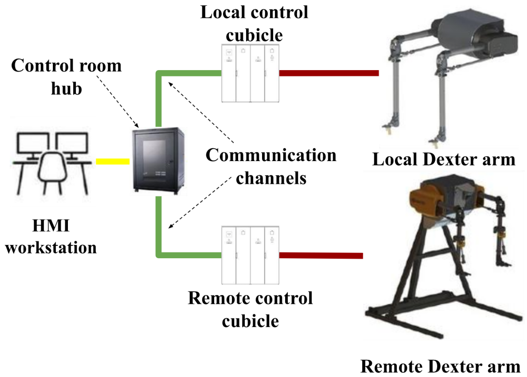
Figure 2.
The experimental setup comprising a mock-up of nuclear waste sorting test-bed. (a) DexterTM local and remote arms. (b) Remote arm with associated sensors and sorting table.
Figure 2.
The experimental setup comprising a mock-up of nuclear waste sorting test-bed. (a) DexterTM local and remote arms. (b) Remote arm with associated sensors and sorting table.
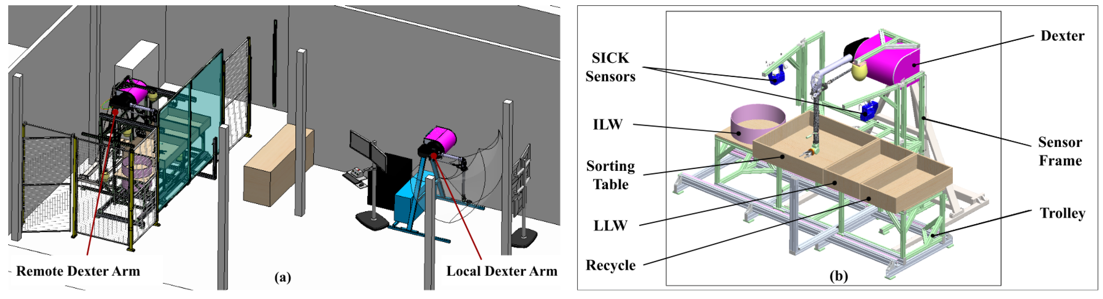
Figure 3.
Top level system process flow for DexterTM system based nuclear Sort and Segregation application
Figure 3.
Top level system process flow for DexterTM system based nuclear Sort and Segregation application
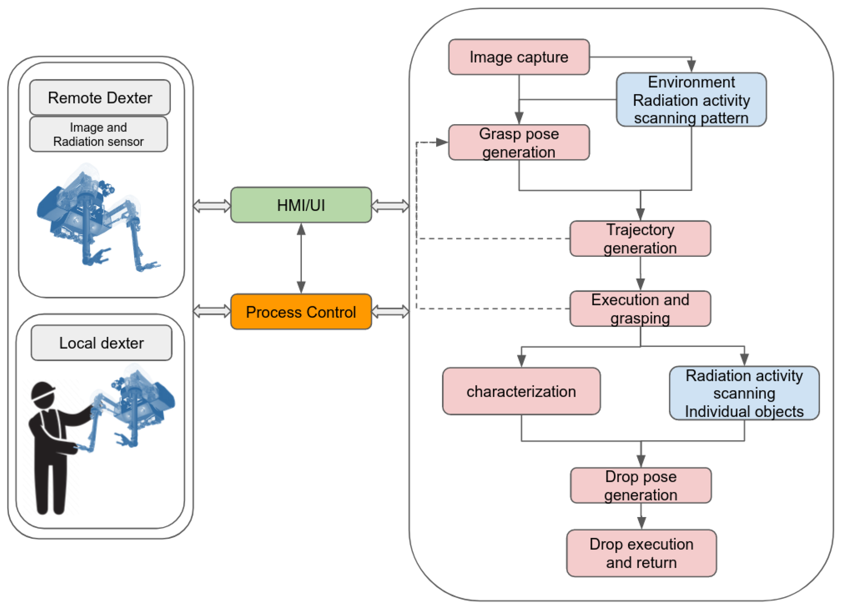
Figure 4.
Nuclear sort and segregation system architecture
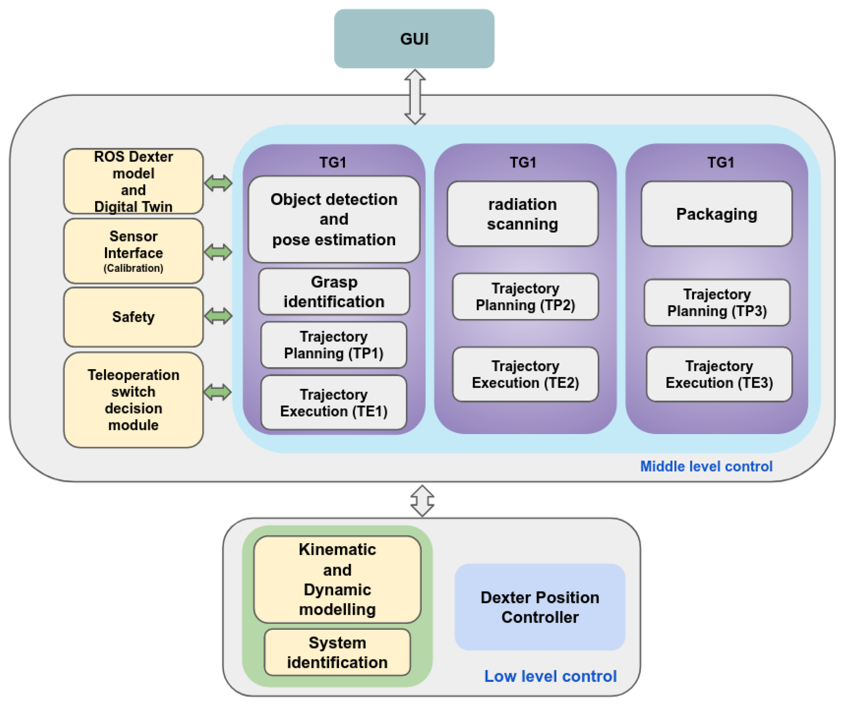
Figure 5.
Frame definition of the DexterTM manipulator.
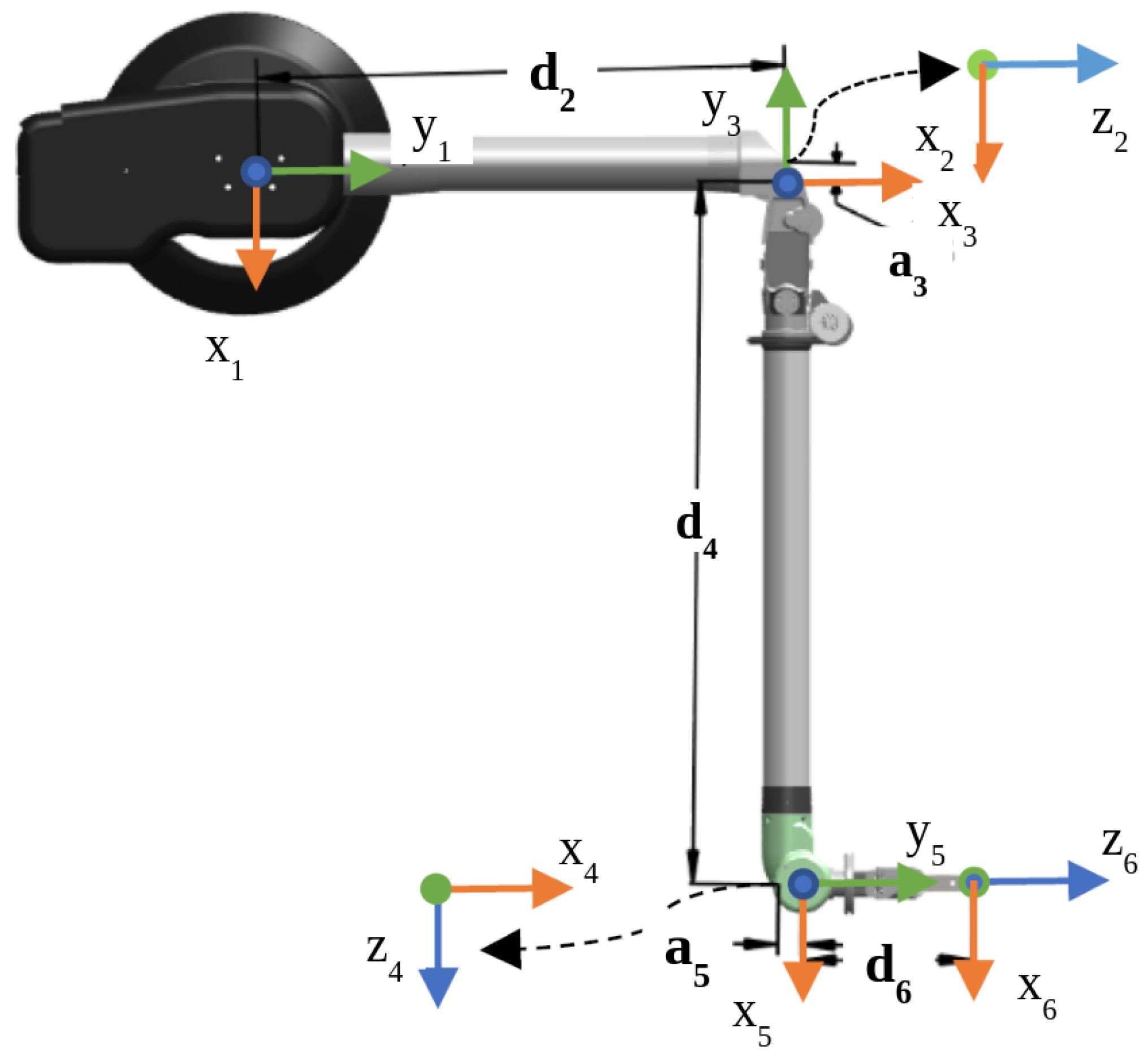
Figure 6.
Dexter dynamic model parameter identification process.
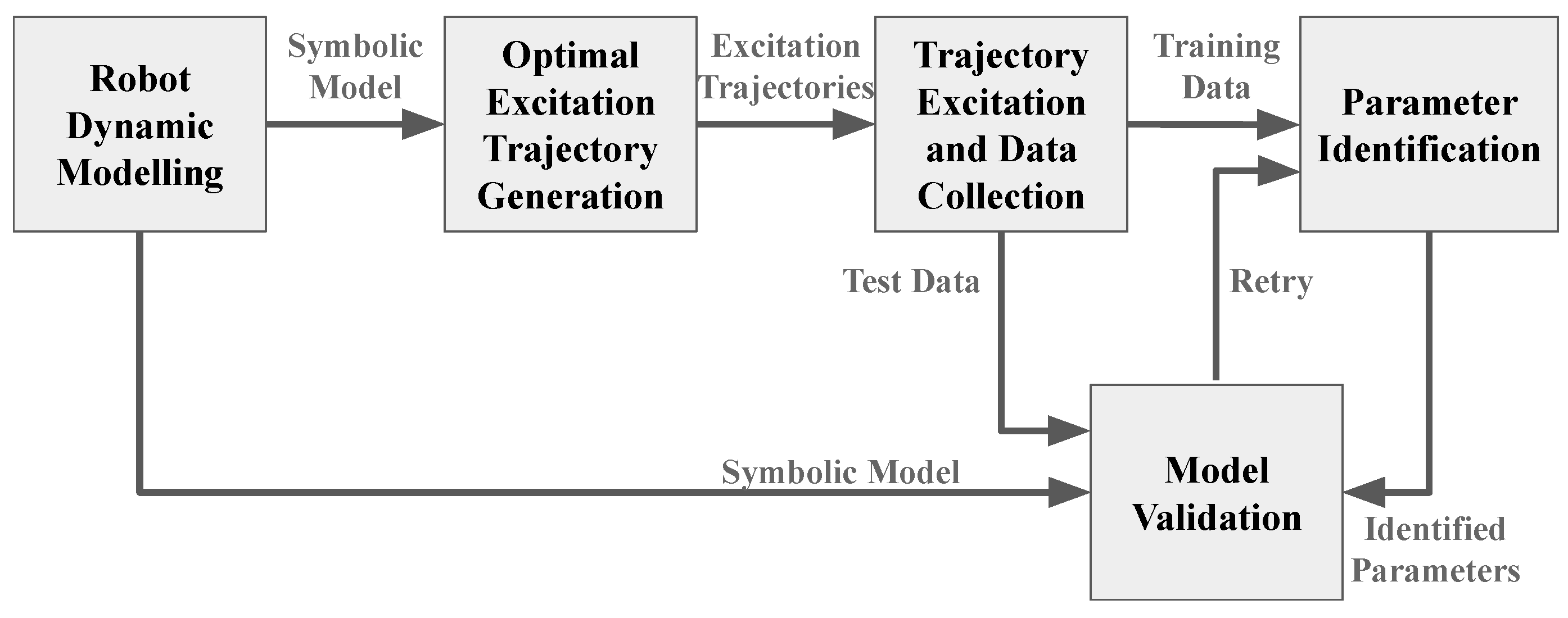
Figure 7.
Joint space feedforward nonlinear control scheme.
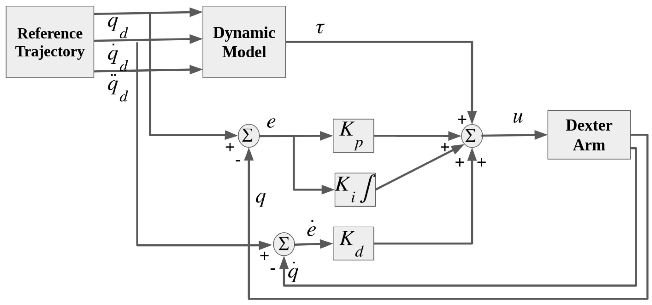
Figure 8.
Octomap of the environment and ROS-Rviz simulation model.
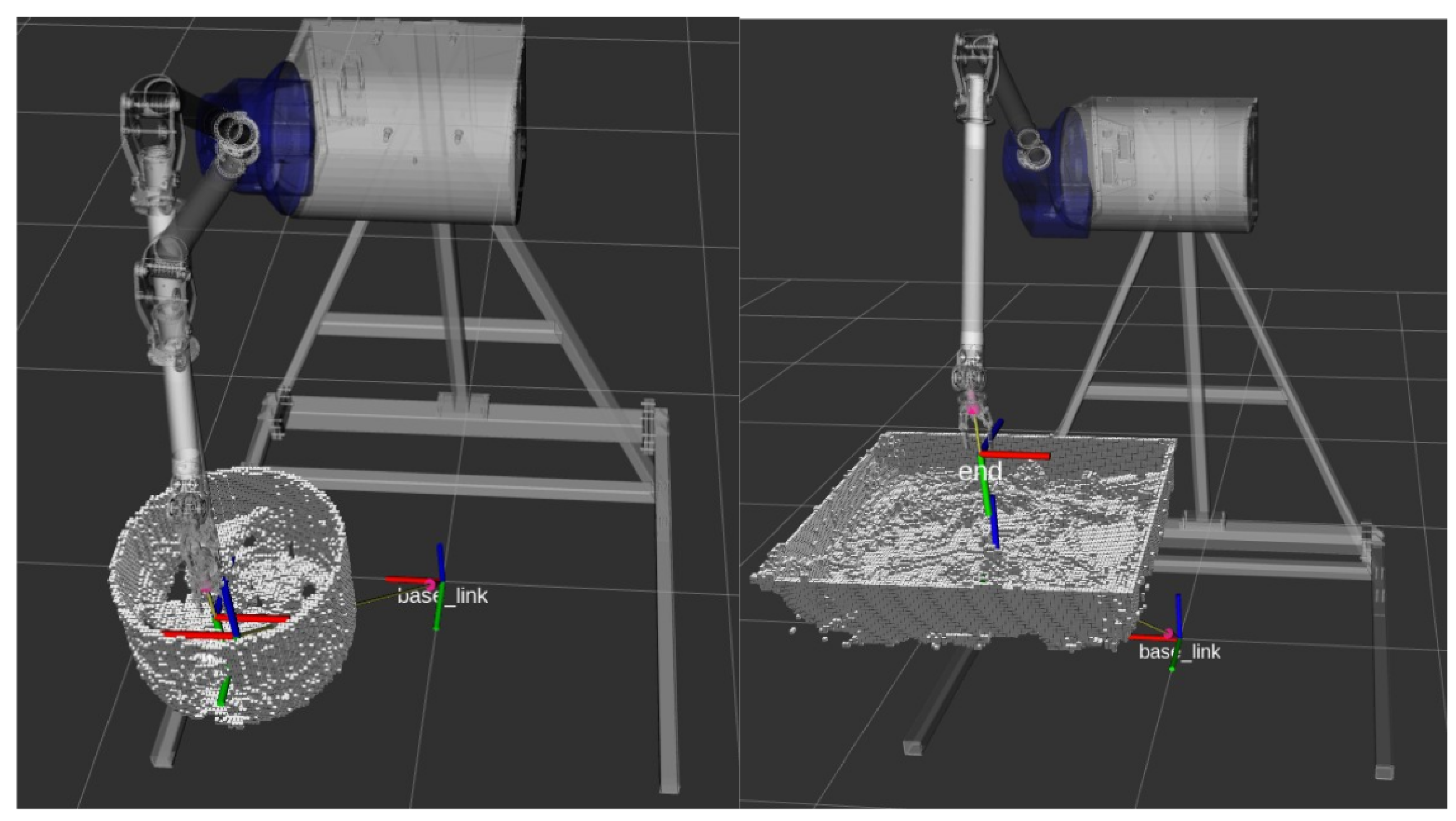
Figure 9.
Curve fitting to mass estimation.
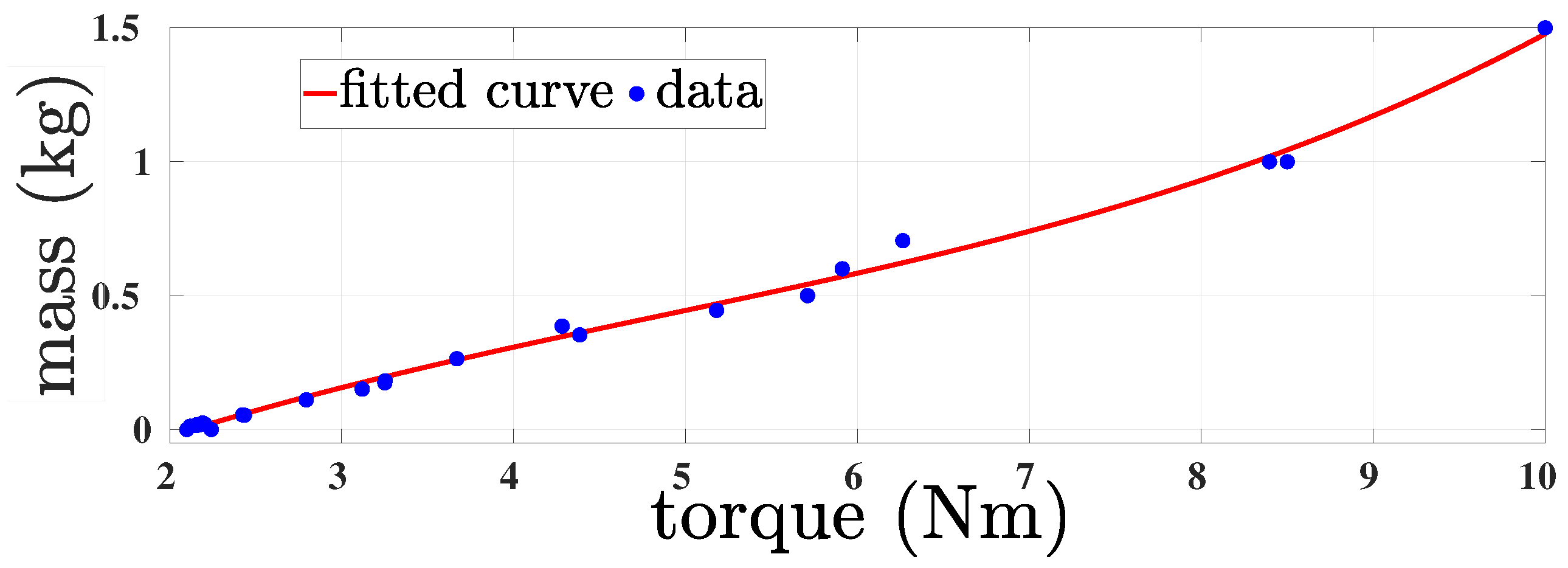
Figure 10.
Fourier series based excitation trajectories generated for dynamical parameter identification of DexterTM manipulator. Joint trajectories for (a) training and (b) testing.
Figure 10.
Fourier series based excitation trajectories generated for dynamical parameter identification of DexterTM manipulator. Joint trajectories for (a) training and (b) testing.
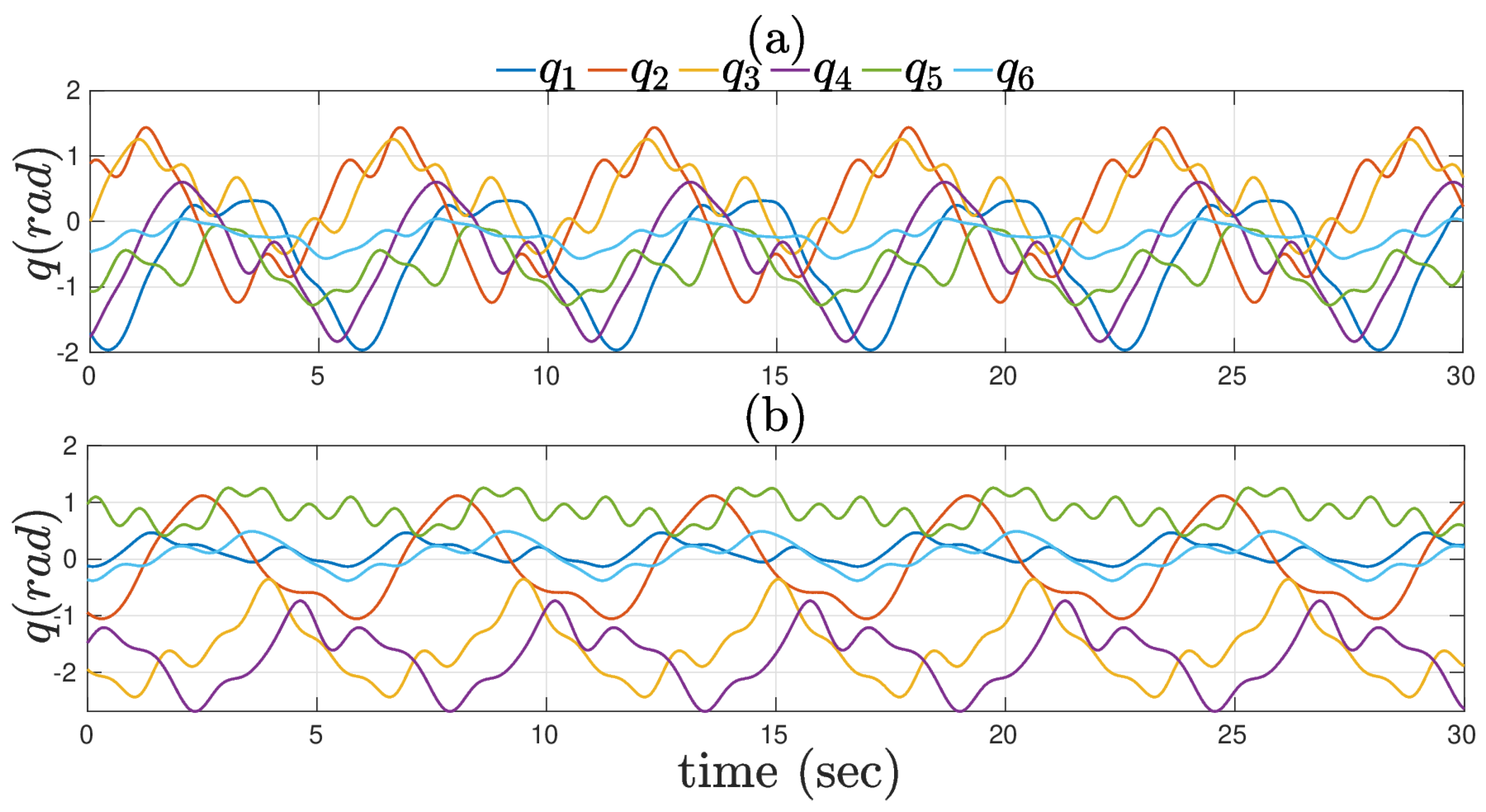
Figure 11.
Predicted and measured torques for the test trajectory using estimated dynamical parameters of DexterTM manipulator.
Figure 11.
Predicted and measured torques for the test trajectory using estimated dynamical parameters of DexterTM manipulator.
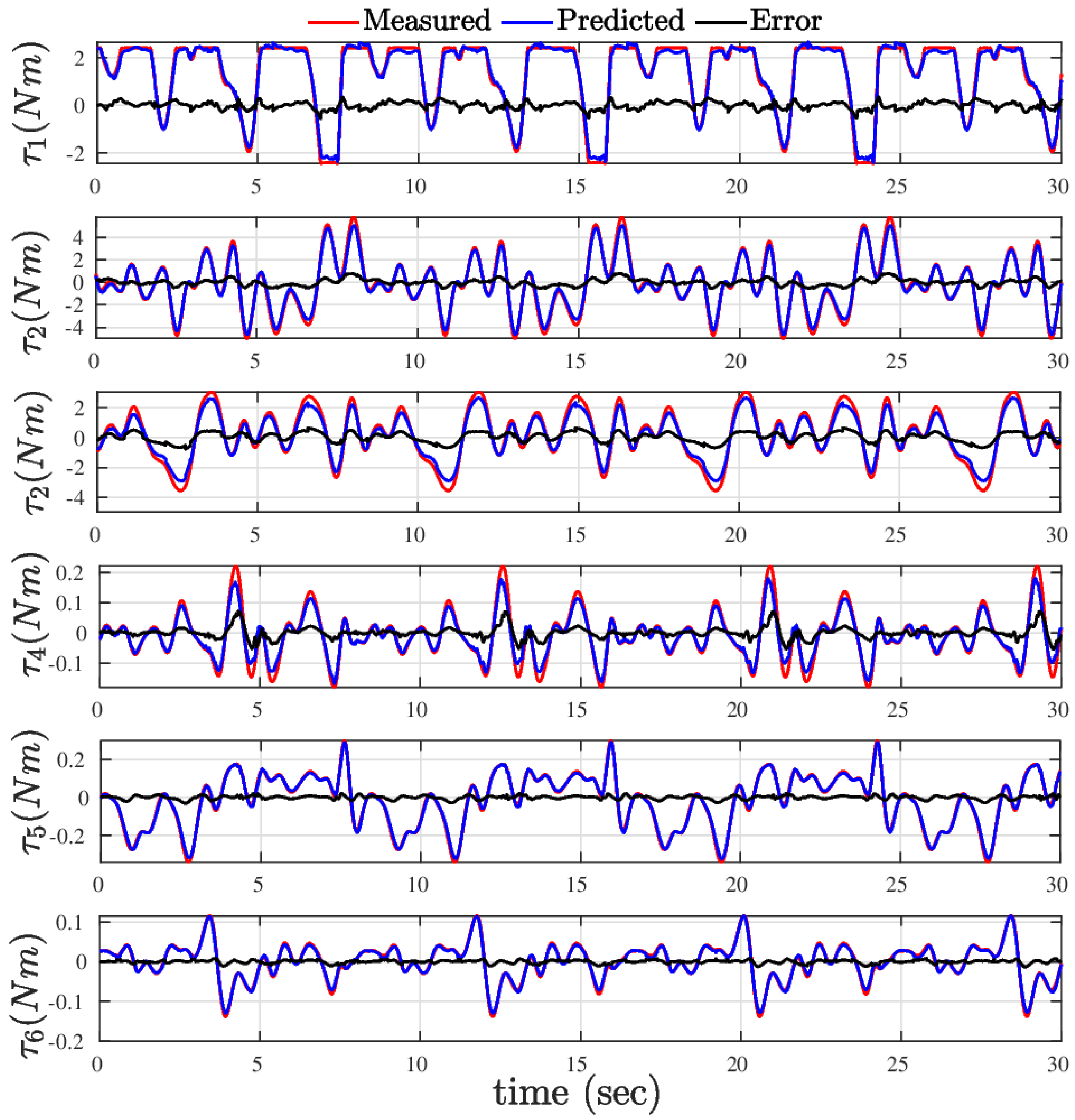
Figure 12.
Result of object detection and classification from two RGB-D images of a scene. Images from left to right shows the test objects in the environment from two cameras, their depth images, Multiview Stereo (MVS) reconstruction and filtered point cloud, and SoftGroup model-based classification and object detection outputs.
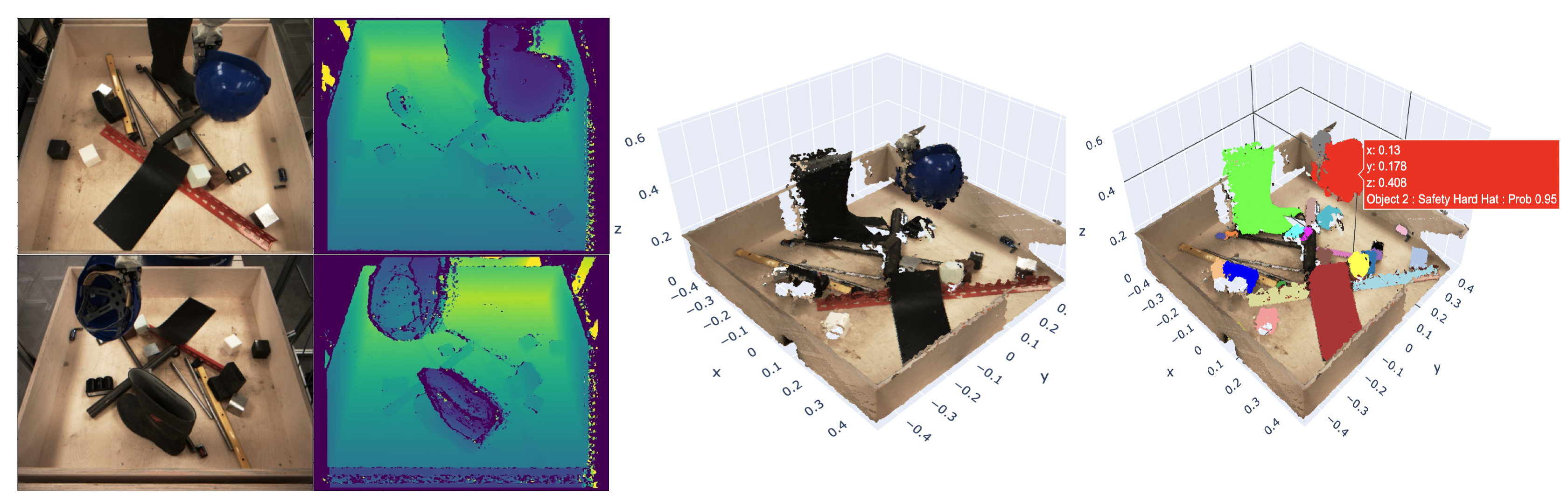
Figure 13.
Single object point cloud reconstruction from three different object pose performed by DexterTM after grasping and the category classification result.
Figure 13.
Single object point cloud reconstruction from three different object pose performed by DexterTM after grasping and the category classification result.
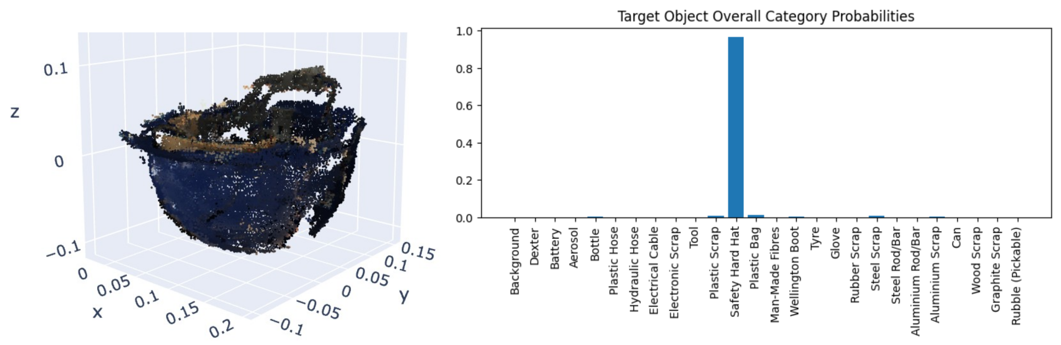
Figure 14.
Radiological surveying: objects, radiation scan trajectories, and radiation levels.
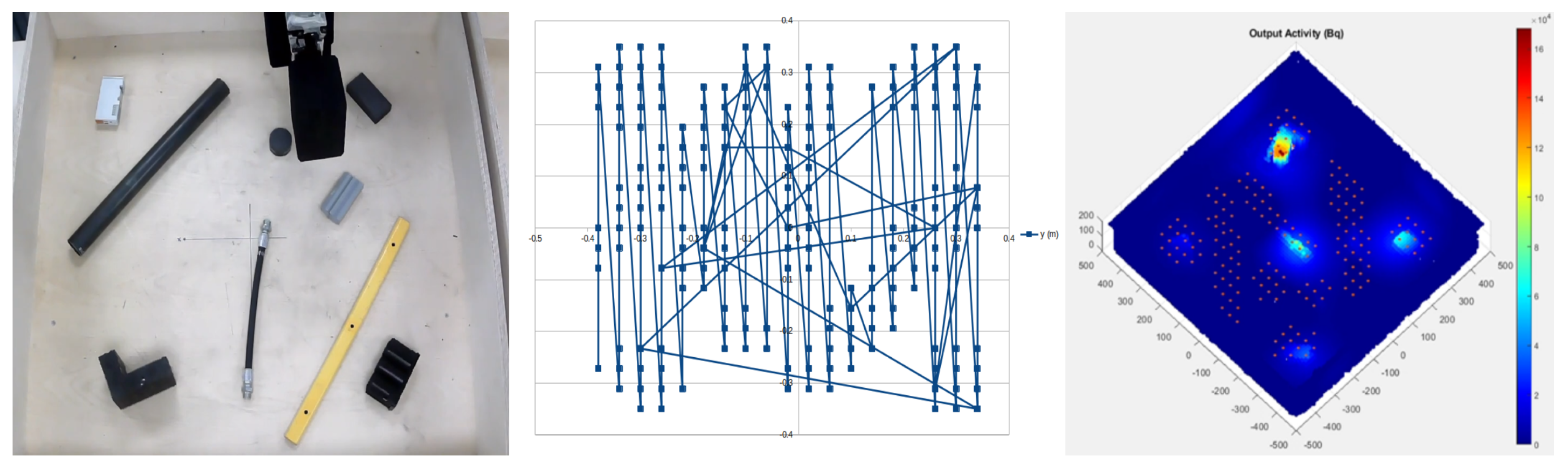
Figure 15.
Grasp pose generation results from two object piles.
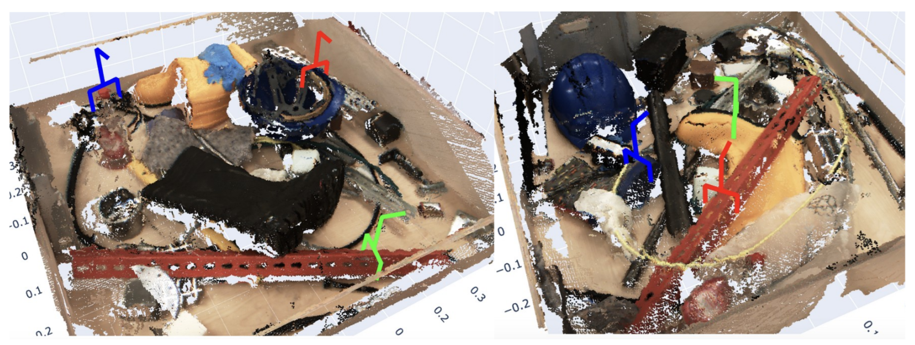
Figure 16.
Geometry characterizations of wellington boot (Row 1) and Plastic hose (Row 2). Column 1: 3D point cloud of the environment. Column 2: Watertight mesh generated from detected object point cloud. Column 3: Geometrical characterization of detected object.
Figure 16.
Geometry characterizations of wellington boot (Row 1) and Plastic hose (Row 2). Column 1: 3D point cloud of the environment. Column 2: Watertight mesh generated from detected object point cloud. Column 3: Geometrical characterization of detected object.
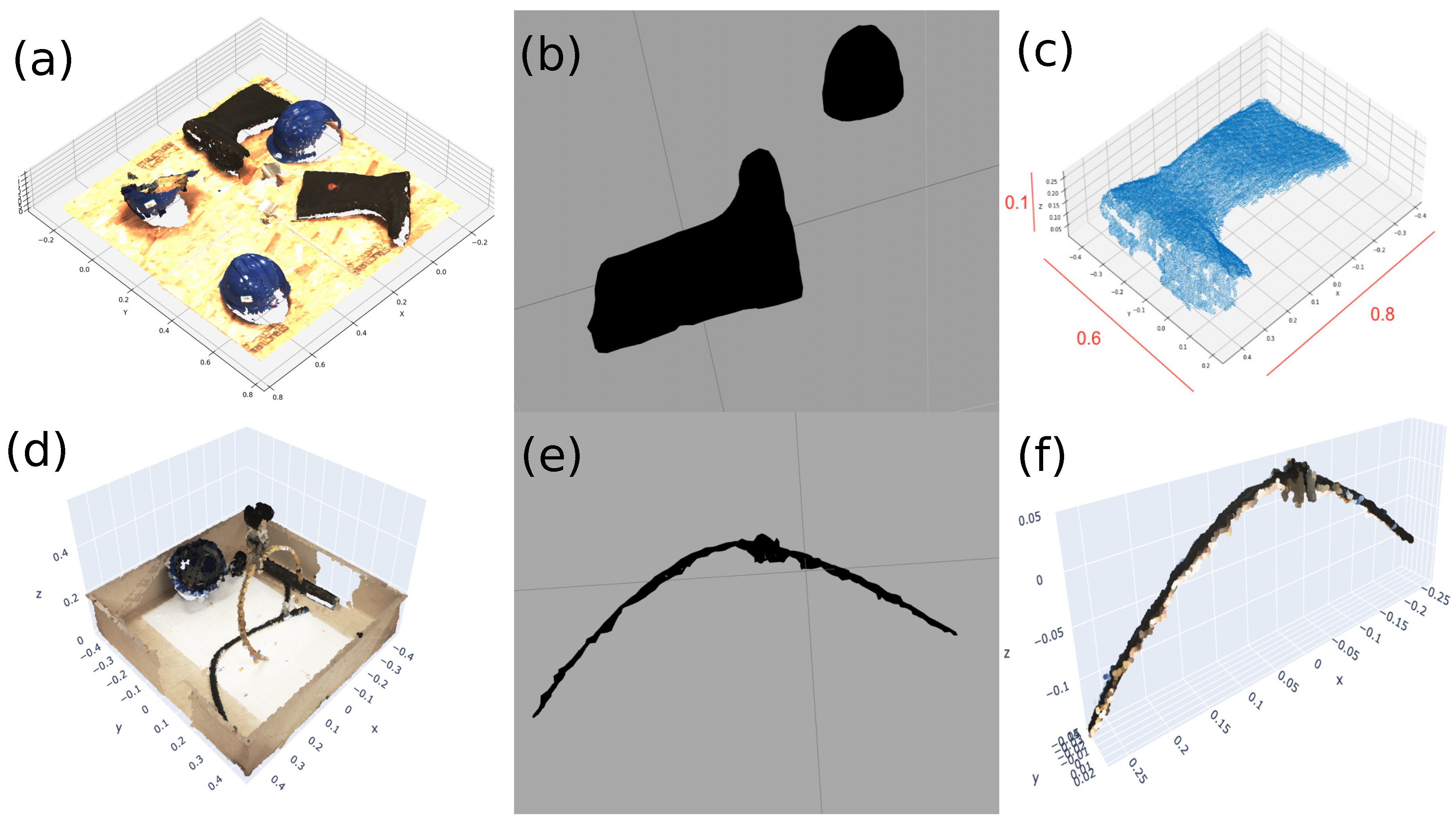
Figure 17.
Experimental result of the bin packing.
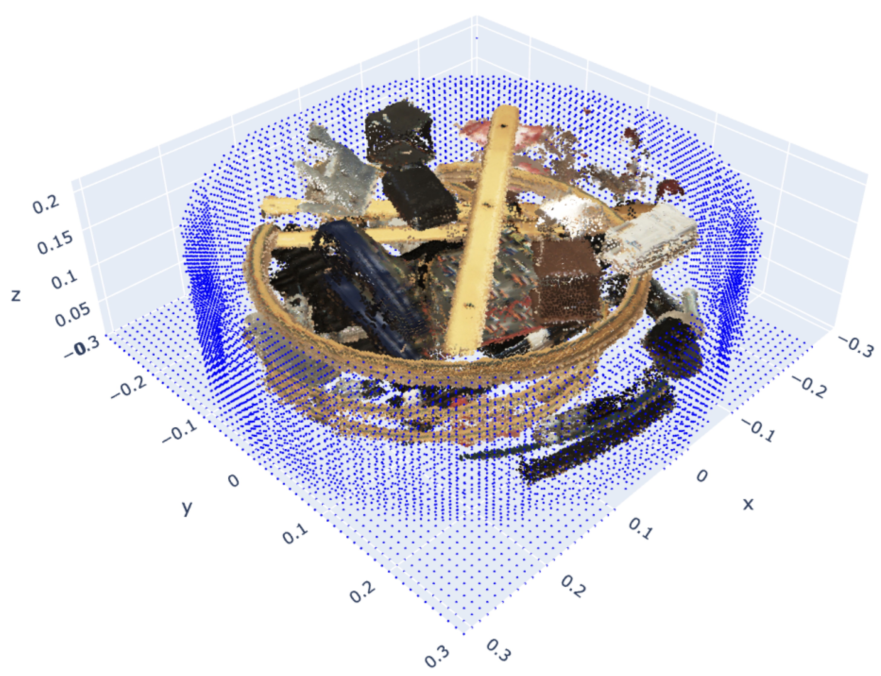
Figure 18.
Full system demonstrator.
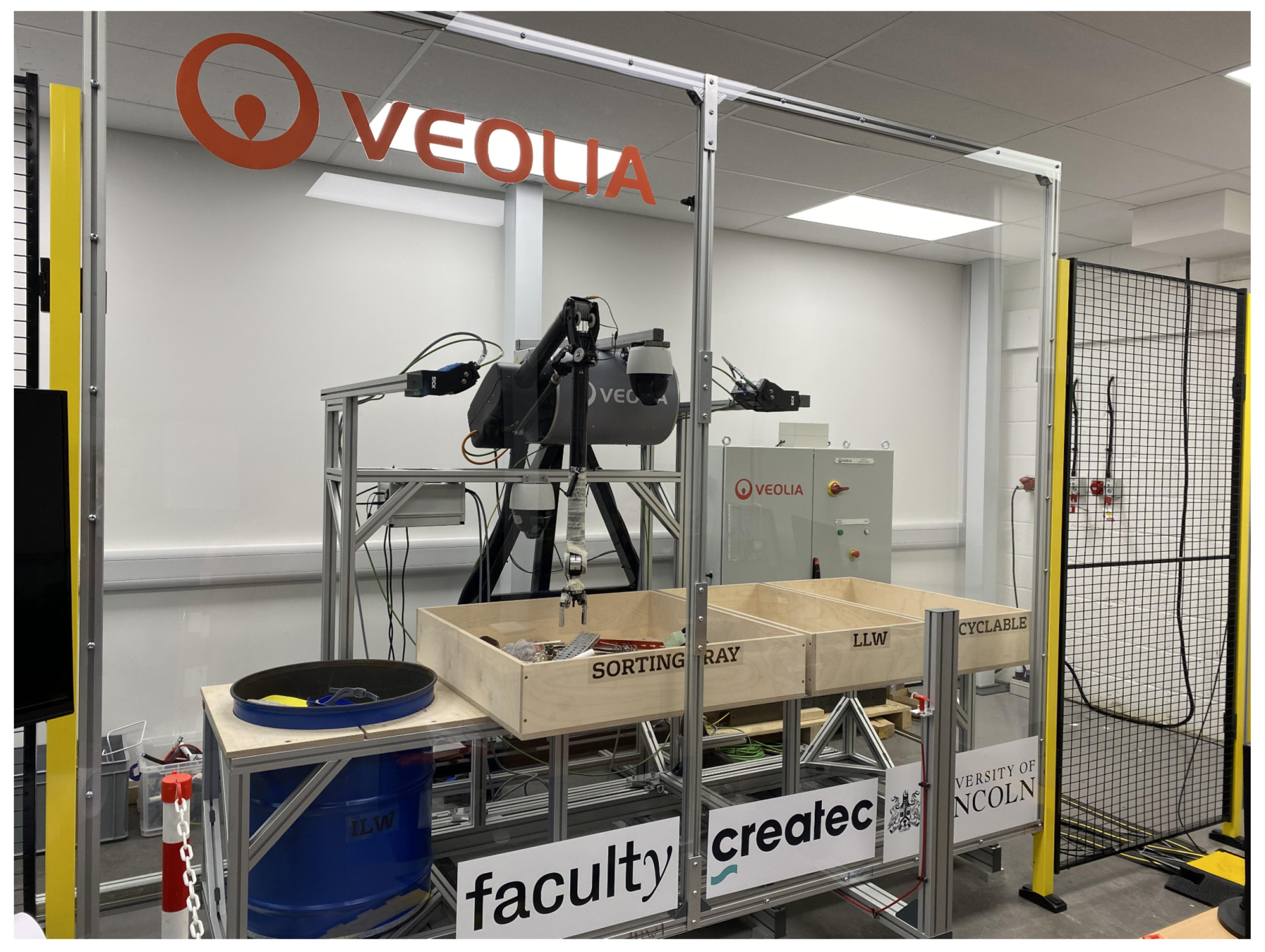
Figure 19.
Execution of the integrated system from picking to dropping for four example objects.
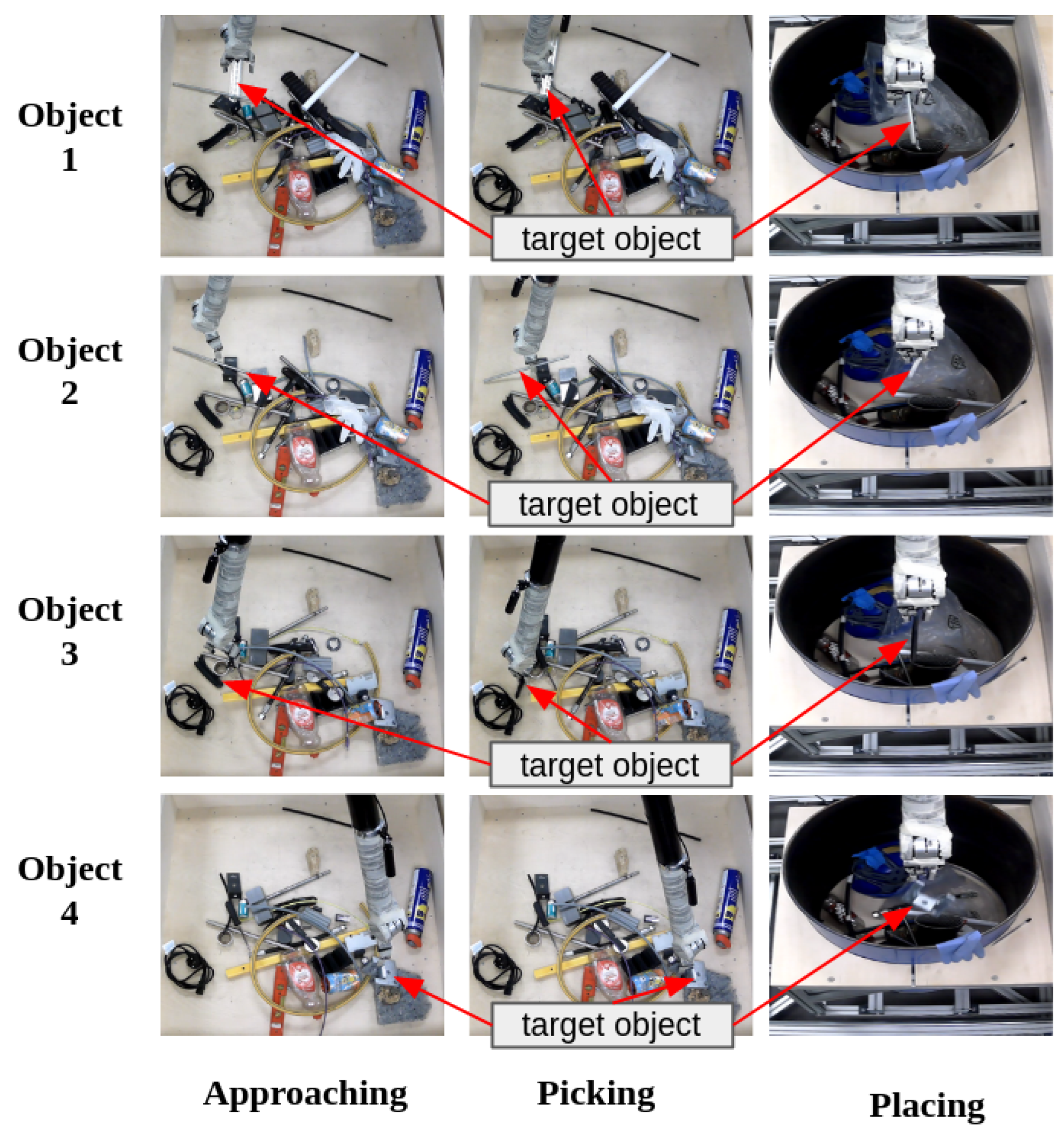

Table 1.
DH PARAMETERS OF DEXTERTM ROBOT.
| joint | ||||
| 1 | 0 | 0 | ||
| 2 | 0 | |||
| 3 | 0 | |||
| 4 | 0 | |||
| 5 | 0 | |||
| 6 | 0 |
Table 2.
Joint torque and position tracking mean percentage error and standard deviation of the training and test trajectories.
Table 2.
Joint torque and position tracking mean percentage error and standard deviation of the training and test trajectories.
| joint | Torque Tracking (Nm) | Position Tracking (rad) | ||||||
| Train | Test | Train | Test | |||||
| % | Std. | % | Std. | % | Std. | % | Std. | |
Table 3.
Sample of objects and category
| Object Name | Object Category |
|---|---|
| Safety Hard Hat, Plastic Scrap, Glove, Electronic Scrap |
Plastic |
| Man-Made Fibres | Man-Made Fibres |
| Wellington Boot | Rubber |
| Steel Rod/Bar | Steel |
| Can | Metal |
| Steel Scrap | Plastic+Metal |
Table 4.
Performance comparison of the bin packing algorithms.
| Algorithm | Center | Random | Lower | Orth. Low | Tetris |
|
Total Packed Object |
22.2 | 27.6 | 31.0 | 34.8 | 38.4 |
|
Total Objects Volume |
12.567 | 14.465 | 15.708 | 18.453 | 20.408 |
|
Container Voidage |
30.686 | 28.796 | 27.553 | 24.808 | 22.853 |
|
% of Container Voidage |
70.933 | 66.564 | 63.69 | 57.345 | 52.826 |
|
Average pose gen run time |
0.00052 | 0.00428 | 0.0047 | 0.00909 | 0.74237 |
Table 5.
The database of sorted objects and their characteristics. A record of packed objects is generated as part of the developed framework of autonomous sort and segregation system.
Table 5.
The database of sorted objects and their characteristics. A record of packed objects is generated as part of the developed framework of autonomous sort and segregation system.
| Category | Material | Category probability |
Material probability |
Estimated volume |
Surface area |
Length |
Width |
Height |
Alpha activity |
Beta activity |
Estimated mass |
Density avg |
Destination |
|---|---|---|---|---|---|---|---|---|---|---|---|---|---|
| Safety Hard Hat |
Plastic | 96.7 | 98.6 | 3050 | 5650 | 31.6 | 28.6 | 18.2 | 1.44 | 10.1 | 484 | 159 | ILW |
| Man-Made Fibres |
Man-Made Fibres |
95.2 | 95.3 | 1130 | 2590 | 26.2 | 23.8 | 18.2 | 4.9 | 34.2 | 74.1 | 656 | ILW |
| Plastic Scrap |
Plastic | 52.8 | 53.1 | 1780 | 2420 | 36 | 30.4 | 9.4 | 7.02 | 48.9 | 436 | 244 | ILW |
| Safety Hard Hat |
Plastic | 97.2 | 99.1 | 2410 | 4620 | 31 | 27.4 | 19.2 | 4.9 | 34.2 | 469 | 195 | ILW |
| Man-Made Fibres |
Man-Made Fibres |
95.8 | 96.0 | 2370 | 2160 | 28 | 21.4 | 15 | 2.51 | 17.5 | 18.1 | 765 | ILW |
| Wellington Boot |
Rubber | 58.6 | 60.0 | 3190 | 8810 | 46.4 | 36 | 15.8 | 4.9 | 34.2 | 222 | 694 | ILW |
| Steel Rod/Bar |
Steel | 87.4 | 99.5 | 31.6 | 150 | 22.4 | 4.2 | 2.6 | 2.51 | 17.5 | 254 | 8.03 | ILW |
| Coke can |
Metal | 79.9 | 80.1 | 209 | 429 | 13 | 7.2 | 6.6 | 1.12 | 7.83 | 30 | 143 | Recycle |
| Steel Scrap |
Plastic + Metal |
99 | 48.4 | 113 | 536 | 24 | 10.6 | 6.4 | 4.9 | 34.2 | 334 | 2.95 | Recycle |
| Wood Scrap |
Stone | 99 | 38.4 | 66.2 | 336 | 16 | 15.2 | 4.6 | 2.51 | 17.5 | 95.8 | 1.45 | Recycle |
| Medical Glove |
Plastic | 99 | 49.5 | 401 | 1270 | 27.6 | 12.4 | 10 | 1.12 | 7.83 | 37.1 | 927 | Recyc. |
| Electronic Scrap |
Plastic | 99 | 24.2 | 56.6 | 278 | 11.2 | 7.2 | 6 | 858 | 5.98 | 42.4 | 749 | Recycle |
| Plastic Scrap |
Plastic | 51.5 | 53.3 | 330 | 1330 | 26 | 22.8 | 7.6 | 1.12 | 7.83 | 121 | 366 | LLW |
Table 6.
A record generated as part of developed sort and segregation framework for obtaining each packed container information.
Table 6.
A record generated as part of developed sort and segregation framework for obtaining each packed container information.
| Container | ILW | LLW | Recyclable |
|---|---|---|---|
| Total number items | 7 | 1 | 5 |
| Total mass (kg) | 2.41 | 0.121 | 0.539 |
| Total net volume | 0.0148 | 0.00033 | 0.000846 |
| Total surface area | 2.85 | 0.133 | 0.285 |
| Total alpha activity (MBq/kg) | 38 | 1.12 | 10.5 |
| Total beta/gamma activity (MBq/kg) | 264 | 7.83 | 73.3 |
| Container fill level | 23.4 | 2.2 | 7.9 |
| Container voidage | 13.5 | 77.0 | 83.6 |
Disclaimer/Publisher’s Note: The statements, opinions and data contained in all publications are solely those of the individual author(s) and contributor(s) and not of MDPI and/or the editor(s). MDPI and/or the editor(s) disclaim responsibility for any injury to people or property resulting from any ideas, methods, instructions or products referred to in the content. |
© 2025 by the authors. Licensee MDPI, Basel, Switzerland. This article is an open access article distributed under the terms and conditions of the Creative Commons Attribution (CC BY) license (http://creativecommons.org/licenses/by/4.0/).
Copyright: This open access article is published under a Creative Commons CC BY 4.0 license, which permit the free download, distribution, and reuse, provided that the author and preprint are cited in any reuse.


