Submitted:
08 December 2025
Posted:
09 December 2025
You are already at the latest version
Abstract
The increasing integration of collaborative robots into industrial manufacturing processes necessitates continuous improvements in their mechanical properties. While collaborative robots are designed to enable flexible and safe human-robot interactions, their comparatively low structural stiffness poses a challenge for high-precision machining and heavy assembly tasks. Addressing this limitation is essential for enhancing performance by reducing deformation-related errors and improving overall efficiency in manufacturing processes. This paper proposes an approach for enhancing the stiffness of collaborative robots by means of situational coupling. Initially, an analysis is conducted to determine the kinematic limitations of coupled collaborative robots. Subsequently, the stiffness of coupled collaborative robots is modelled using the finite element method. Experimental stiffness measurements of a collaborative robot are utilized to validate this model. On basis of this model, it is demonstrated, that the approach of coupling has the potential to enhance the stiffness by up to 37.19 times in comparison with a solitary collaborative robot.
Keywords:
collaborative robots
; stiffness
; robot cooperation
1. Introduction
Flexible process automation is playing an increasingly decisive role in the economic competitiveness and sustainability of modern production systems [1]. Due to global market volatility, rising production costs and demographic changes, the use of robots is becoming progressively more important to ensure efficiency gains and production reliability. This is reflected in the continuously rising annual installation rate of robots. This amounted to over 500,000 units each year from 2021 to 2023, and further acceleration of this growth is forecast for the coming years [2]. Collaborative robots (cobots), in particular, are gaining importance due to their unique advantages, the most significant of which is their capability for direct and safe human-robot interaction – a key distinction from industrial robots [3]. This is also reflected in their steadily increasing market share, which reached almost 10 % of total robot sales in 2023 [2].
Despite these advantages, the comparably low structural stiffness k of cobots remains one of the major challenges for their application in high-precision machining processes and assembly work with high process forces FP. Low structural stiffness k can lead to deformations that negatively impact machining speed, process stability and energy efficiency. The open kinematic chain of a serial 6-axis cobot causes the structure to bend, similar to a machine tool frame in C-design, which leads to a deterioration in the pose accuracy T at the tool center point (TCP) and thus to errors in the execution of the cobot’s task, see Figure 1a.
Higher structural stiffness k not only improves the pose accuracy T, payload capacity and process stability but also extends the range of industrial tasks that cobots can reliably perform and thus facilitates a more flexible and safe production. Numerous research projects therefore focus on increasing structural stiffness k, whereby a distinction can be made between design and compensatory measures. Design measures focus on increasing structural stiffness k by modifying the robot structure. Implementation of these measures is generally only possible retrospectively or iteratively, if at all, by means of extensive conversion work. According to Grote [4], the differentiation of robots in terms of their kinematics can be categorized into three distinct classifications: open, closed and partially closed chains. The serial arrangement of arm members and the resulting long-cantilevered arm structure result in open kinematic chains that exhibit low structural stiffness k. Integration of a parallelogram mechanism between axes 2 and 3 alleviate the load on the drive of axis 2, thereby enhancing the structural stiffness k and positional accuracy T of the robot [5]. However, the closed kinematic sub-chain imposes constraints on flexibility and working space. Completely closed kinematic chains are also characterized by high structural stiffness k with lower flexibility and mobility. In this context, Tanev, Yeshmukhametov et al., and Fang et al. investigated hybrid serial-parallel kinematic chains [6,7,8]. In contrast, numerous robot manufacturers prioritize increasing the robot arm's cross-section to enhance its structural stiffness, as evidenced by the findings of Wu et al. [9]. However, an increase in the arm’s cross-section results in an elevated dead weight, concurrently compromising the robot’s dynamic performance. An alternative approach was presented by Lai et al. [10], wherein two serial 3-axis industrial robots were permanently connected. The main structure is equipped with a spindle at the end effector. The support structure is attached to the end effector of the main structure. During the machining process, the support structure is anchored to a fixed point within in the working space. In this configuration, the system employs parallel kinematics with serial arms. In this coupled operating state, a parallel connection of the two Cartesian stiffnesses kkart of the serial arms has been postulated in regard to the structural stiffness k. Conversely, compensatory measures are intended to enhance positional accuracy T without the need for structural modifications. The prevailing focus of research in this field is the development of globally applicable compensation measures. These measures are based on models that describe the causes of error in the robot’s kinematic model [11,12,13]. Depending on the complexity of the models under consideration, Roth et al. [14] introduced a distinction between three calibration categories:
- level-1 calibration: Compensation for joint axis angle errors,
- level-2 calibration: Compensation for geometric errors (regarding angle errors and arm lengths),
- level-3 calibration: Compensation for non-geometric errors (e. g. elastic and thermal deformations, friction, gear backlash, gear ratio errors).
As demonstrated in numerous studies, the implementation of a level-2 calibration results in a 90 % enhancement in positional accuracy T [15]. However, it proves inadequate for processes characterized by high process forces FP and accuracy requirements due to the low structural stiffness k. While the gradual increase in model complexity enhances model quality, it concurrently complicates parameter identification. Furthermore, the complexity of the model is constrained by the necessity of a sufficiently brief calculation time.
In light of the aforementioned context, this paper proposes an innovative approach to improving the stiffness k by means of situational coupling of two 6-axis cobots. Due to the optimized force flow in the coupled operating state, a significant increase in stiffness k is expected, similar to a machine tool in O-design, see Figure 1b. Coupling of industrial robots is proposed by Goebels et al. [16], Neusser et al. [17], Mühlbeier et al. [18] and Ye et al. [19], however, these studies are limited to conventional industrial robots. The systematic coupling of cobots has not yet been explored and the characteristic features of cobots fundamentally impose different requirements for achieving safe and fully synchronized cobot coupling [20]. Most importantly, the lightweight and compliant design driven by safety requirements is a key characteristic of cobots and should be preserved. Therefore, it is essential to specifically enhance the structural stiffness k through the coupling of two cobots in order to ensure precise and stable collaboration without compromising their fundamental safety advantages.
2. Concept for the Situational Coupling
From the results of the aforementioned studies concerning the coupling of conventional industrial robots it is assumed that situational coupling in the overlapping workspace of two cobots offers the opportunity of direct integration of tasks with high process forces FP and accuracy requirements. Therefore, it is hypothesized that such a configuration will enhance flexibility in cobot-based process chains, thereby facilitating automation and increasing productivity, even with small batch sizes. Additionally, this approach ensures that both cobots maintain their inherent high degree of flexibility and dynamics in the decoupled operating state, see Figure 2.
This requires the use of a flexible coupling interface, which enables a fully automated coupling and decoupling process of both cobots and fulfils the conflicting requirements of lightweight construction, high stiffness, high precision and low costs. Furthermore, the native control system of both cobots has to be adapted. It is essential to ensure that both cobots follow a synchronized trajectory. The technical prerequisites in the form of two cobots within range of each other are already in place in many industrial cobot-based process chains, so that the approach can be easily implemented and integrated into industry.
3. Kinematic Model for the Coupled Operating State
In order to both coordinate the cobots in the coupled operating state and to generate possible joint angle configurations for the stiffness model, a mathematical representation of the coupled kinematics is required. The cooperative cobot system is considered a combination of two serial cobots I, I ϵ {A|B}. In addition to the two Cartesian base coordinate systems KI, I ϵ {A|B}, a working coordinate system Kx is introduced. The constant homogeneous transformation matrix represents the rotation and displacement of Kx relative to KI. The homogeneous transformation matrix between the base coordinate system and the end effector flange can be determined according to Formula 1.
In Formula 1, represents the homogeneous transformation matrix between the working coordinate system and the working point, while represents the homogeneous transformation matrix between the working point and the end effector flange of the cobot. Figure 3 illustrates the definitions of the homogeneous transformation matrices.
The so-defined coupled kinematics was implemented in the software MATLAB R2023b of the company The Mathworks Inc., Natick, USA. Figure 4 exemplifies the resulting coupled working space given a base distance dh = 1,500 mm.
For modelling purposes, the forward and backward kinematics of the cobot of type UR10e from the company Universal Robots A/S, Odense, Denmark, were implemented. For the sake of simplicity, it will be referred to as UR10e from here on out. Since the end effectors of the cobots should be connected to each other preventing any relative motion, a point constraint was defined, accordingly. The distance between the base coordinate systems of the cobots was set to dh = 1,500 mm, as this provides the optimal ratio of work space to installation area. The maximum working space between the cobots corresponds to the maximum reach of the cobots, which is lUR10e = 1,300 mm. Evidently, due to inherent structural limitations, including the diameter of the cobot's base db = 190 mm, a base distance dh = 1,300 mm is infeasible. To ensure sufficient space, this results in a base distance of dh = 1,500 mm. Consequently, the resulting working space volume is determined to be VA,coup = 1.06 m3. Comparing the usable working space volume of a single UR10e VA,UR10e ≈ 3.50 m3 with that of the coupled cobots reveals that the latter is only about 30.23 %. In order to avoid noticeable loss of flexibility through permanent coupling, the implementation of fully automated coupling mechanisms is of crucial importance. This enables either a high degree of flexibility or high stiffness k to be achieved, depending on the requirements of the application.
4. Stiffness Tests of the Cobot
In order to enable an increase in system stiffness k throughout coupling of cobots, it is essential to investigate the stiffness k of a single UR10e. Therefore, stiffness tests were carried out. According to the manufacturer’s datasheet, the UR10e’s maximum payload capacity is mP,UR10e = 12.50 kg. Its reach measures to lR,UR10e = 1,300 mm and its net weight to mE,UR10e = 33.50 kg [21].
4.1. Experimental Procedure
To determine the stiffness k of the UR10e, a radial force Frad is applied to its end effector and the corresponding displacement u of the end effector is measured. To carry out the tests, the end effector of the UR10e is moved to a specific position. This position along the base coordinate system’s x-axis corresponds both to the UR10e’s nominal operational configuration and to the midpoint of the simulated working space. The positions in the y- and z-direction remained invariant, due to the given environmental conditions. During the application of the radial force Frad at the designated operating point, the UR10e is in switched-on mode without performing any movement, so that the experiments could be conducted under quasi-static conditions. The radial force Frad is applied to the UR10e’s end effector in the respective opposite direction from which it has been moved to its target position. A type 9257B multi-component dynamometer from the company Kistler Group, Winterthur, Switzerland is used to measure the radial force Frad. The radial force Frad is using the LabVIEW interface from the company National Instruments, Austin, USA and is applied by a fine thread screwing device, which is connected to the multi-component dynamometer by a screw connection. The displacement u of the end effector is measured using a laser triangulator of the type ILD2200-10 from the company MICRO-EPSILON Optronic GmbH, Dresden, Germany. Both radial force Frad and displacement u are recorded at a sampling rate of fs = 1 Hz. The entire measurement procedure was repeated three times. Figure 5 illustrates the experimental setup.
4.2. Results and Evaluation
Figure 6 shows the mean values of the measured displacement u in the x- and y-direction subject to radial force Frad imposed on the end effector along with the respective standard deviation. In order to determine the in-plane and out-of-plane stiffness k of the UR10e, radial forces Frad were applied in both the x- and y-direction. The amplitude of which ranged up to two orders of magnitude. Utilizing a weighted least square algorithm, the average stiffness of kx = 95.94 N/mm in the x-direction and ky = 57.42 N/mm in the y-direction was obtained on the basis of the three repetitions. Thus, the UR10e exhibits a structural stiffness k which is about 67 % higher in x-direction than in y-direction.
The maximum displacement ux,max ≈ 3.09 mm in the x-direction occurred at the corresponding maximum radial force of Frad,x,max ≈ 220 N. In accordance with a priori expectations, the UR10e demonstrated a capacity of a maximum radial force of only Frad,y,max ≈ 82 N in the y-direction, resulting in a displacement of uy,max ≈ 7.01 mm. This is consistent with the observations made during the experiments, where at a threshold of radial force Frad,y ≈ 75 N and displacement uy ≈ 1.42 mm any additional rotation of the fine thread screwing device would result in only a slight increase in the measured radial force Frad,y, while a substantial increase in the corresponding displacement uy occurred. In x-direction, the same amplitude of radial force Frad resulted in a displacement of merely ux = 0.73 mm. To characterize these spatial differences in the UR10e’s behavior, the pointwise stiffness kpw, as defined in Formula 2, was determined.
Figure 7, accordingly, illustrates the mean values of pointwise stiffness kpw in the x- and y-direction subject to radial force Frad imposed on the end effector along with the respective standard deviation.
The observed anisotropy in the stiffness k may be attributed to the UR10e’s kinematic structure, in particular the general arrangement and alignment of its joints and the resulting transmission of force and momentum, as well as the pose under consideration within the conducted tests.
5. Stiffness Evaluation of Cobots in Coupled Operating State
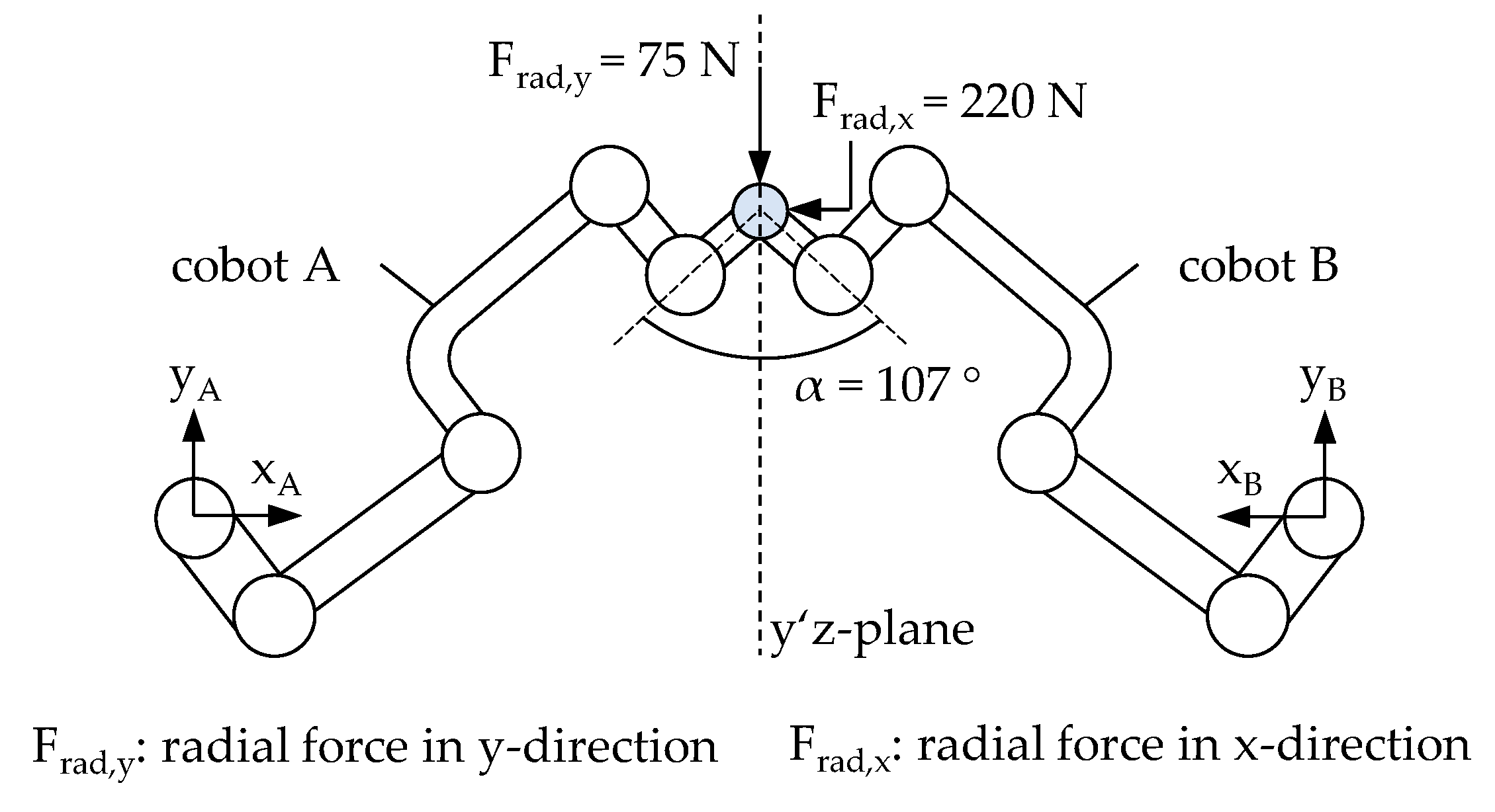
To investigate the effect of coupling two cobots regarding compound stiffness kC, a simulation-based analysis was conducted. For this purpose, a multibody simulation model was implemented in the finite element software Ansys 2025 R2 provided by the company Ansys Inc., Canonsburg, USA. In order to obtain general insides in the overall effect, certain assumptions have been made, e. g. the simplification to a quasistatic problem due to slow force application, negligible influence of material properties as all arms are assumed to be stiff and discrete localization of all compound compliances sC in the six or twelve cobot joints, respectively. The joints were configured as purely rotational, with one degree of freedom each, and independent torsional stiffnesses cT,i. These torsional stiffnesses cT,i were utilized as parameters for phenomenologically adjusting the behavior of a single cobot. Therefore, experimental data presented in chapter 4.2 have been reproduced numerically varying each joint’s torsional stiffness cT. In coupled operating state the coupling object between the two cobots was modelled as stiff, preventing any relative motion between the end effectors and reflecting a typically state of pretension in these components, see Figure 3. Boundary conditions at the bases were set according to the fixed clamping of both cobots to ground. The model has been implemented such that the second cobot is mirrored to the first one with respect to the y’z-plane resulting in a relative angle of α = 107 °, see Figure 8.
Loading has been configured according to single cobot experiments as stated in chapter 4.2 and was applied to the common node of the end effectors. The simulation could prove exemplarily expediency of the concept, as in the coupled operating state an increased compound stiffnesses kC,x ≈ 212 N/mm and kC,y ≈ 2.95 kN/mm was observed. It should be noted that an additional side effect of the angled arrangement is that both cobots compensate for the more compliant spatial direction of the other. This results in an overall stiffer structure, as the results illustrate.
6. Conclusions
In this paper, the concept of situational coupling of two cobots was presented. For this purpose, the resulting working space of the coupled cobots was determined by a kinematic model. Furthermore, pose related stiffness in the planar main axis system of a single cobot of type UR10e was investigated experimentally. Therefore, radial forces Frad,i in the x- and y-direction have been applied to the UR10e's end effectors and the resulting displacement ui has been measured. The results of the analysis yield a stiffness ratio η ≔ kx/ky ≈ 1.67 with respect to the UR10e’s base coordinate system.
Consecutively, a multi-body simulation model of the UR10e was implemented and parameterized phenomenologically utilizing experimentally obtained measurement data. The adapted parameter values then were used to numerically investigate the coupling of two UR10e. Compound stiffnesses kC,i exhibited an enhancement in comparison to single operating state, with an increase of approximately 200 % in x-direction and approximately 5,940 % in y-direction. In light of these findings, an angular arrangement of the two cobots was found to be advantageous in terms of compensating for the respective more compliant direction of movement. These findings substantiate the conceptual viability of situationally coupled cobots and indicate the necessity for further research to investigate the scope of applications in which the structural advantages of collaborative industrial robots can be leveraged. Future research, therefore, may aim to extend this investigation throughout the entire working space, incorporating stiffness characteristics of cobot’s arm segments. Furthermore, the determination of an optimal angle α in the coupled operating state with regard to compound stiffness kC and optimal pretension of the end effectors represent potential subjects for further investigation.
Author Contributions
Conceptualization, methodology, writing—original draft preparation, formal analysis, visualization, Marie-Noëlle Fielers; software, validation, data curation, Marie-Noëlle Fielers and Thomas Pache; writing—review, Eckart Uhlmann; supervision, project administration, funding acquisition, Eckart Uhlmann; All authors have read and agreed to the published version of the manuscript.
Funding
This research was funded by the Federal Ministry for Economic Affairs and Energy and the project organizer VDI/VDE Innovation + Technik GmbH, grant number 16TNW0008E.
Data Availability Statement
The raw data supporting the conclusions of this article will be made available by the authors on request.
Conflicts of Interest
The authors declare no conflicts of interest.
References
- International Federation of Robotics (IFR). World Robotics Report. 2023. [Google Scholar]
- Müller, C. World Robotics Industrial Robots 2024. VDMA Services GmbH, Frankfurt, Germany, 2024. Available online: https://ifr.org/img/worldrobotics/Executive_Summary_WR_2024_Industrial_Robots.pdf (accessed on 28 March 2025).
- Patil, S.; Vasu, V.; Srinadh, K.V.S. Advances and perspectives in collaborative robotics: a review of key technologies and emerging trends. In Discover Mechanical Engineering; Warangal, India, 2023. [Google Scholar]
- Dubbel, 22. Aufl.; Brecher, C., Dannenmann, E., Dorn, L., Pritschow, G., Siegert, K., Spur, G., Grote, K.-H., Eds.; Springer-Verlag, 2007. [Google Scholar]
- Reinkober, S. Fräsbearbeitung von Nickelbasislegierungen mit Industrierobotern. Fraunhofer-Institut für Produktionsanlagen und Konstruktionstechnik;Dissertation, Fraunhofer IRB-Verlag, 2017. [Google Scholar]
- Tanev, T.K. Kinematics of a hybrid (parallel–serial) robot manipulator. Mechanism and Machine Theory 2000, 3, 1.183–1.196. [Google Scholar] [CrossRef]
- Yeshmukhametov, A.; Kalimoldayev, M.; Mamyrbayev, O.; Amirgaliev, Y. Design and kinematics of serial/parallel hybrid robots. 2017 3rd International Conference on Control, Automation and Robotics; pp. 162–165.
- Fang, L.; Liang, F.; Sun, L. Comparative Study of Stiffness Modeling Methods for A Novel Industrial Robotic Arm with Hybrid Open- and Closed-Loop Kinematic Chains. In Proceedings of the 2018 IEEE International Conference on Mechatronics and Automation (ICMA), Changchun, China, 2018; pp. 1765–1770. [Google Scholar]
- Wu, K.; Li, J.; Zhao, H.; Zhong, Y. Review of Industrial Robot Stiffness Identification and Modelling. Applied Sciences 2022, 12, 8719. [Google Scholar] [CrossRef]
- Lai, C.Y.; Villacis Chavez, D.E.; Ding, S. Transformable parallel-serial manipulator for robotic machining. The International Journal of Advanced Manufacturing Technology 2018, 97, 2.987–2.996. [Google Scholar] [CrossRef]
- Weigold, M. Kompensation der Werkzeugabdrängung bei der spanenden Bearbeitung mit Industrierobotern. Dissertation, Technische Universität Darmstadt, 2008. [Google Scholar]
- Klimchik, A. Enhanced stiffness modeling of serial and parallel manipulators for robotic-based processing of high performance materials. Ecole Centrale de Nantes, Dissertation, 2012. [Google Scholar]
- Peng, J.; Ding, Y.; Zhang, G.; Ding, H. An enhanced kinematic model for calibration of robotic machining systems with parallelogram mechanisms. Robotics and Computer-Integrated Manufacturing 2019, 59, 92–103. [Google Scholar] [CrossRef]
- Roth, Z.; Mooring, B.; Ravani, B. An overview of robot calibration. IEEE Journal on Robotics and Automation 1987, 3, 377–385. [Google Scholar] [CrossRef]
- Renders, J.-M.; Rossignol, E.; Becquet, M.; Hanus, R. Kinematic calibration and geometrical parameter identification for robots. IEEE Transactions on Robotics and Automation 1991, 7, 721–732. [Google Scholar] [CrossRef]
- Goebels, M.; Baumgärtner, J.; Fuchs, T.; Mühlbeier, E.; Puchta, A.; Fleischer, J. Milling using two mechatronically coupled robots. Proceedings of 57th CIRP Conference on Manufacturing Systems CMS 2024, Karlsruhe, 2024. [Google Scholar]
- Neusser, Z.; Valasek, M.; Necas, M. Stiffness increase and homogenization by coupled robots; Mechanics Based Design of Structures and Machines: Prague, Czech Republic, 2024. [Google Scholar]
- Mühlbeier, E.; Bauer, V.; Schade, F.; Gönnheimer, P.; Becker, J.; Fleischer, J. Mechatronic Coupling System for Cooperative Manufacturing with Industrial Robots. 56th CIRP Conference on Manufacturing Systems, 2023. [Google Scholar]
- Ye, X.; Schwartz, M.; Hohmann, S. Stiffness Optimized Multi-Robot Behavior Planning using Reduced Hessian Method; IFAC-Papers OnLine: Karlsruhe, 2022; Volume 55, 38. [Google Scholar]
- Kulkarni, A.; Raut, R.; Dhatrak, P. A comprehensive review on configuration, design and programming of robotic systems used in various applications. International Journal of Intelligent Robotics and Applications 2025, 1187–1213. [Google Scholar] [CrossRef]
- Universal Robots Homepage: UR10e Technische Daten. Available online: https://www.universal-robots.com/media/1811481/ur10e-product-factsheet-de-web.pdf (accessed on 17 April 2025).
Figure 1.
Force flow and displacement: (a) open kinematic chain of a 6-axis cobot; (b) closed kinematic chain of coupled cobots.
Figure 1.
Force flow and displacement: (a) open kinematic chain of a 6-axis cobot; (b) closed kinematic chain of coupled cobots.
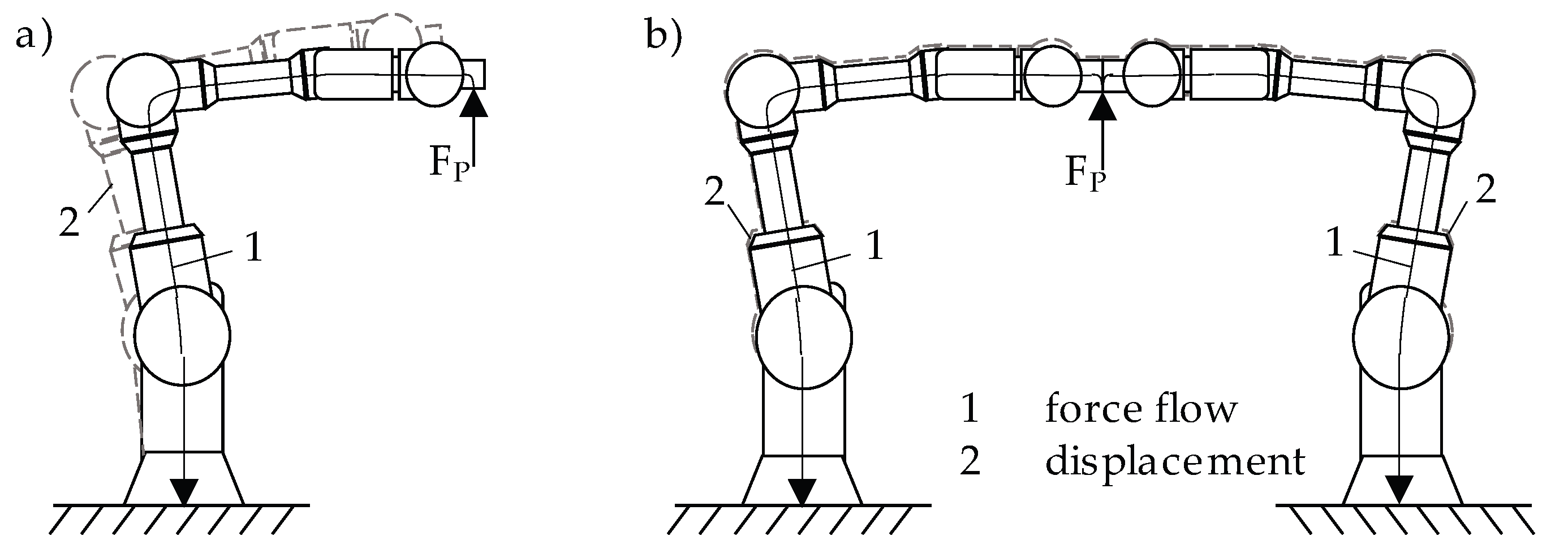
Figure 2.
Organizing the working space of cooperating cobots according to the requirements.
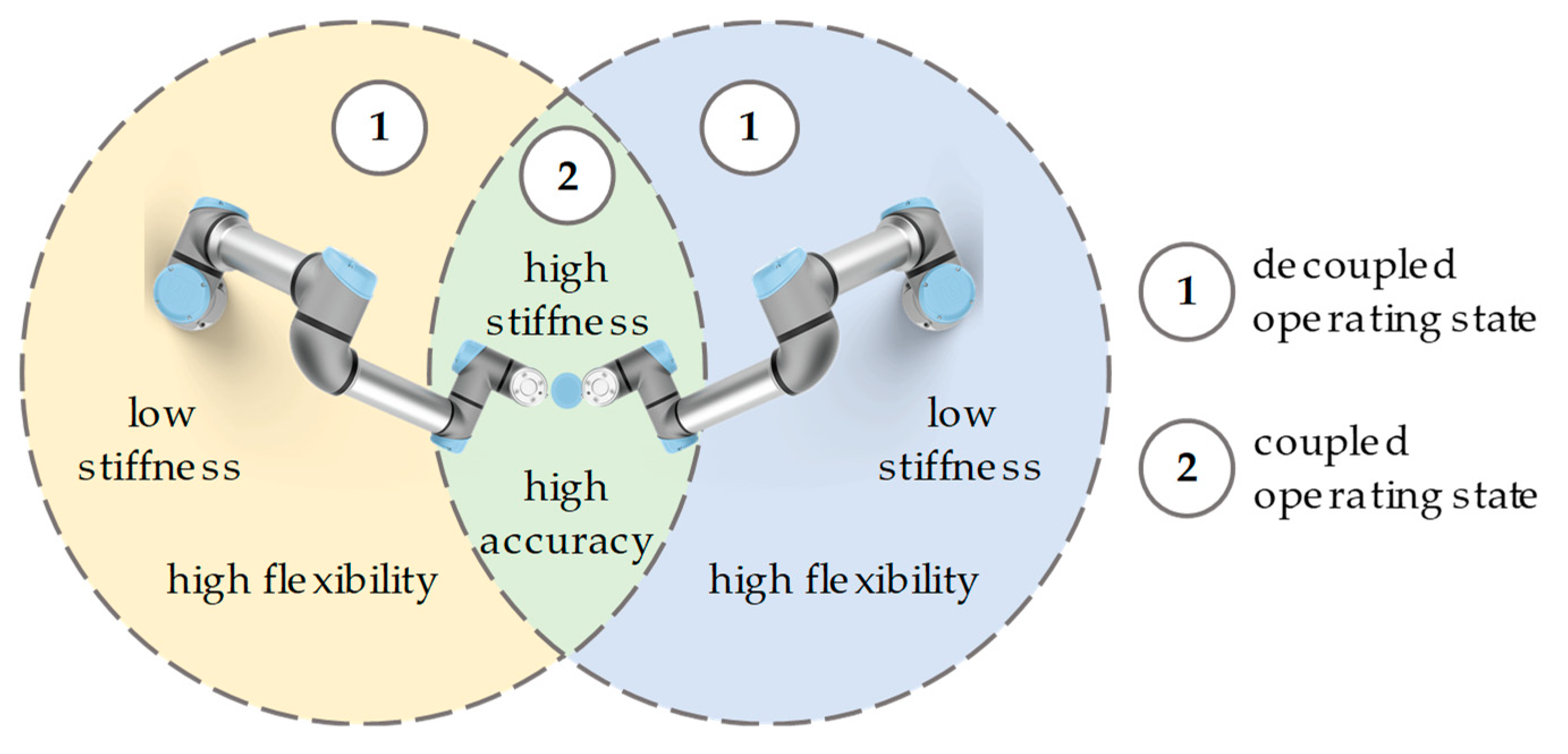
Figure 3.
Kinematics of two cobots in coupled operating state.
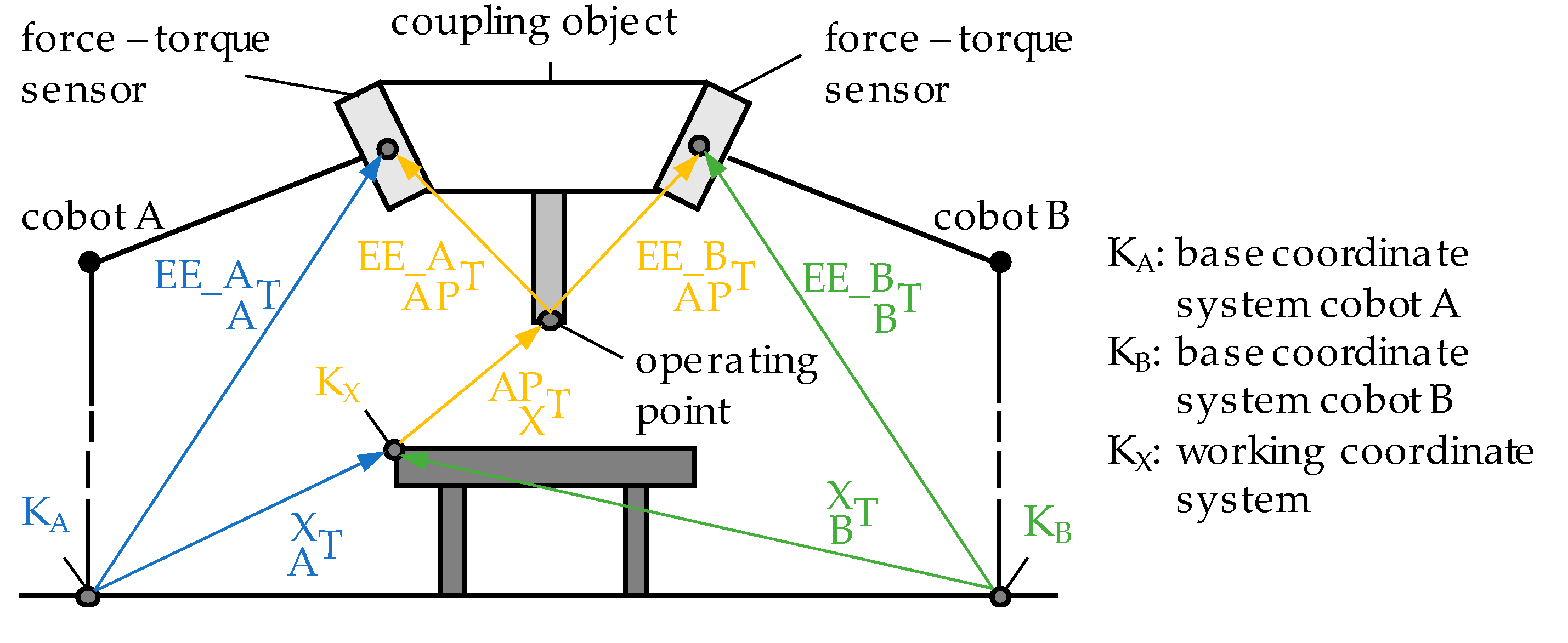
Figure 4.
Simulated working space of two coupled cobots: (a) X-Z-view; (b) X-Y-view.
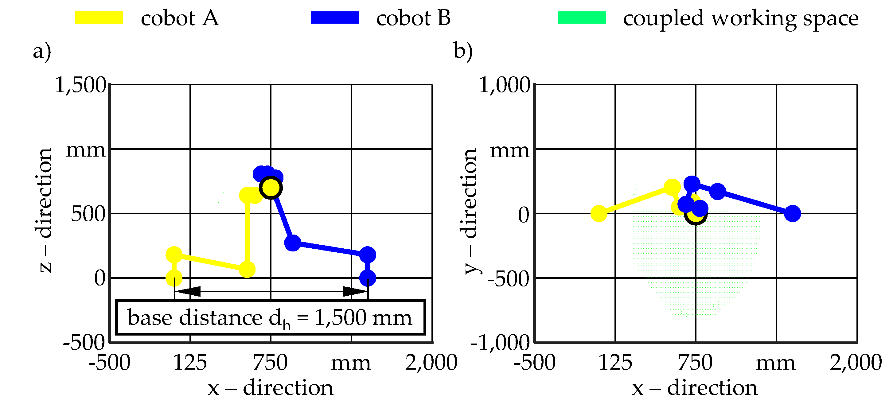
Figure 5.
Experimental setup for stiffness tests with a UR10e.
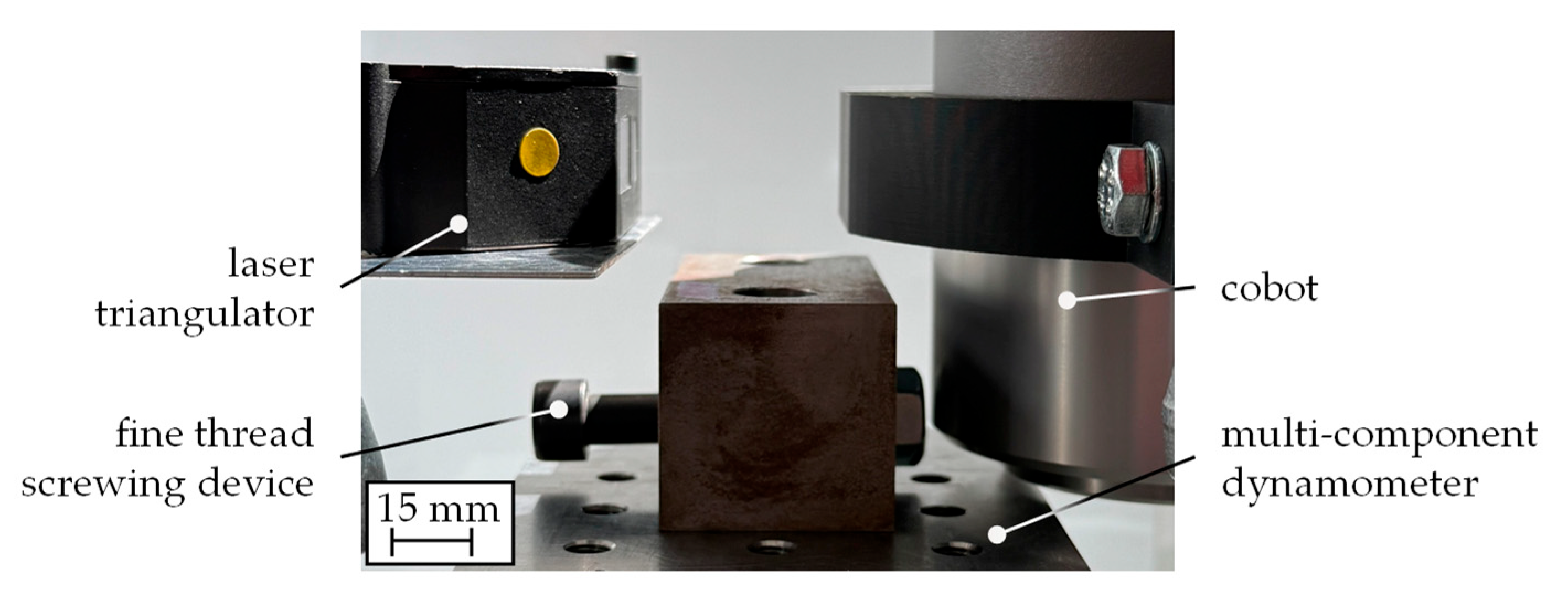
Figure 6.
Displacement-force diagram for measurements conducted with the UR10e.
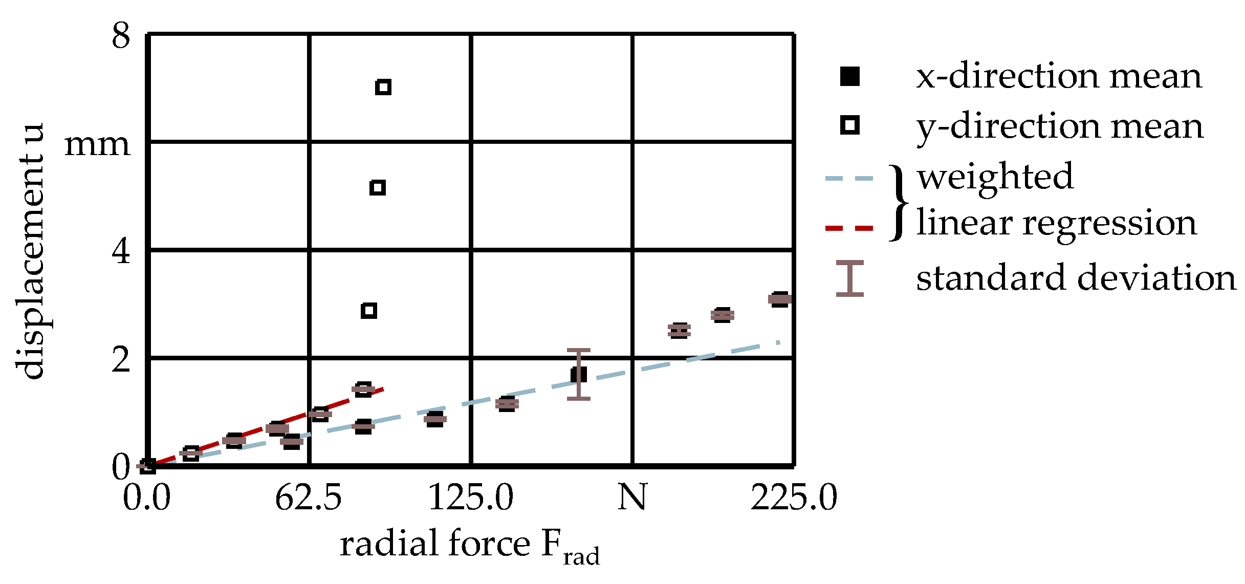
Figure 7.
Pointwise stiffness kpw of the UR10e at the different levels of radial force Frad under consideration.
Figure 7.
Pointwise stiffness kpw of the UR10e at the different levels of radial force Frad under consideration.
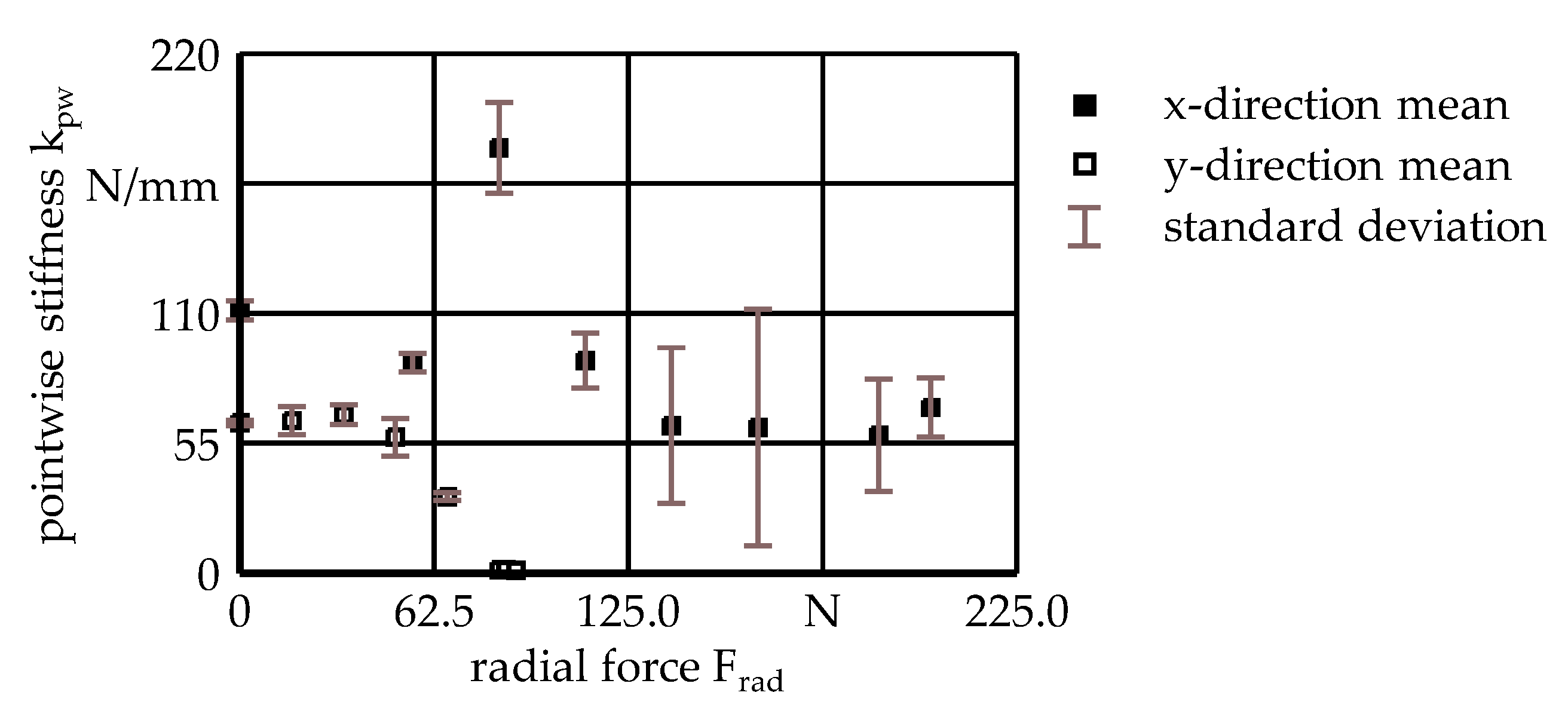
Figure 8.
Schematic of the finite element model in single and coupled operating state.
Disclaimer/Publisher’s Note: The statements, opinions and data contained in all publications are solely those of the individual author(s) and contributor(s) and not of MDPI and/or the editor(s). MDPI and/or the editor(s) disclaim responsibility for any injury to people or property resulting from any ideas, methods, instructions or products referred to in the content. |
© 2025 by the authors. Licensee MDPI, Basel, Switzerland. This article is an open access article distributed under the terms and conditions of the Creative Commons Attribution (CC BY) license (http://creativecommons.org/licenses/by/4.0/).
Copyright: This open access article is published under a Creative Commons CC BY 4.0 license, which permit the free download, distribution, and reuse, provided that the author and preprint are cited in any reuse.


