1. Introduction
In today’s highly competitive industrial environment, manufacturers face increasing pressure to achieve high productivity while reducing time-to-market. As product portfolios expand and product life cycles shorten, conventional manufacturing strategies, optimized for producing large quantities of a few product types, are no longer sufficient. Modern production systems therefore require a high degree of flexibility to efficiently handle product diversity and frequent design modifications.[
1]
Enhancing manufacturing adaptability has led to the development of flexible robotic systems and reconfigurable fixturing technologies [
2]. In this context, the present work investigates the use of passive Stewart–Gough platforms (hexapods) as flexible fixtures for low-volume production environments.
Active parallel mechanisms based on the Stewart–Gough architecture have been widely studied as generic six-degree-of-freedom motion generators in robotics and machine tools since the pioneering works of Gough, Whitehall and Stewart [
3,
4]. These architectures are particularly attractive in applications requiring accurate six degree of freedom pose control, for example in motion simulation, flight simulators, and precision positioning stages. A comprehensive overview of the kinematics, dynamics, singularities, and applications of Stewart platforms is provided in the review by Dasgupta and Mruthyunjaya [
5].
Industrial implementations of Stewart platforms driven by electromechanical actuators and servo controllers have been reported for motion control and trajectory tracking tasks, such as reproducing cycloidal and ocean wave trajectories [
6], or evaluating commercial motion controllers for hexapod operation [
7]. Parallel platforms of this type have also been explored for aerospace related applications [
8] and for base motion compensation in vibration sensitive systems [
9].
However, the proposed hexapods are passive mechanisms without actuators, instead equipped with mechanical brakes that lock the structure in the desired configuration (see
Section 2). To improve static performance and load-bearing capacity, custom designed Cardan joints have been integrated into leg assemblies [
10]. Although this design enhances rigidity, it also introduces additional complexity in the direct and inverse kinematic analyses.
Accurate geometric modeling and calibration of Stewart–Gough platforms remain active research topics. Early work by Zhuang and Roth introduced leg-wise calibration methods for these mechanisms [
11], and a recent survey by Karmakar and Turner provides an extensive review of modern calibration strategies [
12]. Reliable kinematic modeling is essential for estimating the pose of each hexapod and ensuring robust production planning, particularly when multiple platforms simultaneously secure a single workpiece. Earlier hexapod prototypes [
10] omitted joint encoders to reduce cost. However, in the current design, each leg incorporates a linear encoder, allowing precise measurement of leg extension and thereby improving configuration estimation. Nonetheless, encoder data alone are insufficient without a corresponding, accurate kinematic model.
The introduction of preloaded axis offset Cardan joints renders traditional Stewart–Gough kinematic formulations inapplicable. Previous studies, such as [
13], have examined the kinematics and singularities of mechanisms with axis offset Cardan joints, focusing primarily on the identification of all possible solutions. Building upon these foundations, this paper presents a novel iterative kinematic method designed to compute the configuration of a hexapod near a known initial pose. The proposed approach can also be generalized to determine direct and inverse kinematic solutions for hexapods with arbitrary leg geometries.
The remainder of this paper is organized as follows:
Section 2 describes the design and mechanical characteristics of the developed passive hexapod fixtures.
Section 3 and
Section 4 introduce the proposed iterative kinematic modeling approach and outlines its mathematical formulation.
Section 5 presents experimental validation and discusses the accuracy and performance of the proposed method. Finally,
Section 6 summarizes the main findings and outlines directions for future research.
2. Hexapod Design Overview
The mechanical design of the proposed hexapod is based on a passive Gough–Stewart platform engineered to deliver high rigidity and full reconfigurability for robotic assembly applications. The structure comprises two rigid plates: a base plate fixed to the robotic workcell and a top plate outfitted with modular workpiece locating assemblies. These plates are interconnected by six extendable legs, each equipped with a cilindrical joint, an integrated hydro-mechanical brake, and two custom designed Cardan joints at both ends [
14]. This configuration enables the top plate to move freely across all six degrees of freedom during reconfiguration and to be locked precisely in place for operation. When the hydraulic brakes are disengaged, the platform can be repositioned manually or by a robot through a tool-exchange interface mounted on the top plate. Once the desired pose is achieved, the brakes are activated, fixing the structure with exceptional stiffness and positional accuracy.
A key feature of the design is the hydro mechanical braking system integrated into each leg [
15]. Each brake consists of a deformable sleeve surrounding the moving rod and three concentric pressure chambers radially arranged around the outside of the sleeve. In the unpressurized state, the sleeve geometry provides a high radial preload against the rod, generating a large normal force that rigidly locks the leg. When hydraulic pressure is applied to the chambers, the sleeve deforms releasing the contact pressure and letting rod can slide freely. This pressure-to-release principle means that any loss of hydraulic pressure during operation leads to an inherently safe state in which all legs remain locked. The brake, in its locked state, can withstand substantial axial loads without slippage, and its compact geometry and simple hydraulic interface make it well suited for integration into industrial hexapod fixtures and other reconfigurable support systems.
The Cardan joints used in the system introduce several improvements over conventional universal joint configurations. Each joint incorporates non intersecting rotational axes together with a central hub featuring adjustable preload that eliminates play and micro gaps, which are common sources of backlash (see Figure 3). The separation of axes and the adjustable preload contribute to increased structural stiffness when the brakes are engaged. Additionally, the joint geometry promotes more uniform load distribution, reducing wear on the contact surfaces and improving long term reliability. Despite these enhancements, the design maintains a compact form factor while providing high load bearing capacity.
Together, the hydro mechanical braking system and enhanced Cardan joints enable the hexapod to achieve sub millimeter repeatability, minimal backlash, and exceptional rigidity while maintaining a fully passive, low cost design. The modular top plate can be fitted with interchangeable fixtures, such as centering pins and pneumatic lever clamps, allowing adaptation to a wide range of components, for example, various automotive light housings. Furthermore, multiple hexapods can be combined to form a flexible, robotically reconfigurable fixture system. In general, the integration of precision mechanical locking, adjustable kinematic joints, and modular adaptability delivers an optimal balance between flexibility, structural performance, and precision, establishing the hexapod as a highly capable platform for reconfigurable robotic manufacturing systems.
2.1. Encoder Integration
Several authors have employed external vision systems for kinematic calibration of Stewart platforms, including omnidirectional cameras [
16] and stereo vision [
17]. A broader survey of calibration methods for spatial parallel mechanisms using internal and external sensing is provided by Majarena et al. [
18]. Additional approaches exploiting supplementary sensing, such as dedicated motion controllers or industrial servo hardware, have also been reported for calibration and state estimation [
6,
7].
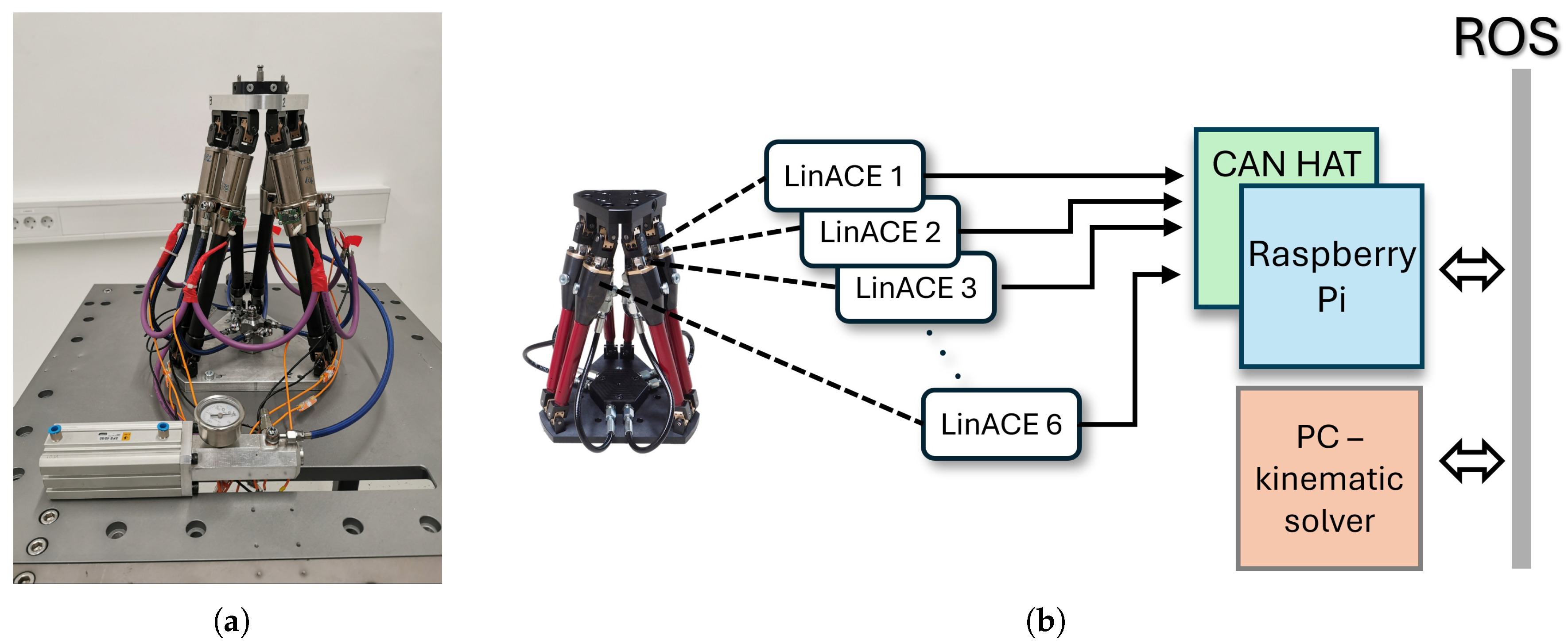
In contrast to these external techniques, the sensor-integrated hexapod developed here uses LinACE™ absolute linear encoders installed on all six legs (
Figure 1(a)). LinACE technology employs variable magnetic permeability (VMP) sensing: an absolute pseudo-random binary sequence is embedded directly into the steel shaft as regions of differing magnetic permeability, which modulate an applied magnetic field. A compact single-die Hall sensor array reads these field variations, and internal signal-processing algorithms reconstruct the absolute position with micrometer-scale accuracy. This solid-state magnetic encoding provides drift-free measurement and preserves absolute position even after power loss.
Each encoder communicates via CAN bus with a Raspberry Pi located in the hexapod base. Because the Raspberry Pi lacks native CAN support, a two-channel isolated MCP2515/SN65HVD230 CAN-HAT ensures robust communication. The Raspberry Pi runs a ROS node [
19] that continuously acquires the encoder values and publishes the raw joint data on the ROS network at 1 Hz. Importantly, the Raspberry Pi functions solely as an edge-level data acquisition device: the inverse kinematic computation of the hexapod pose is performed on an external PC. Once the PC calculates the updated platform pose, the Raspberry Pi records this information in its non-volatile memory (SD card), enabling seamless pose recovery after shutdown or extended storage. The block scheme of the setup is given in
Figure 1(b).
Integrating absolute encoders significantly increases fixture reliability and operational continuity. With measurement accuracy exceeding that of most industrial robots, robot–fixture alignment becomes simpler and more repeatable. Native ROS communication further supports effortless integration into modular robotic workcells, enabling real-time monitoring and automated calibration routines.
A remaining limitation is that the encoders measure only linear leg extensions rather than the full six-degree-of-freedom pose of the top plate. Accurate pose recovery therefore requires solving the hexapod’s inverse kinematics. Conventional models are not directly applicable due to the use of preloaded Cardan joints with non-intersecting rotational axes, which alter the mechanism’s geometry and constraints. To address this, a dedicated computational method was developed to reliably reconstruct the platform pose despite the non-standard joint configuration. The resulting system combines precise sensing, robust embedded communication, and advanced external computation, delivering a reliable and reconfigurable fixture well suited for modern robotic manufacturing environments.
3. Direct and Inverse Kinematics of Parallel Mechanisms
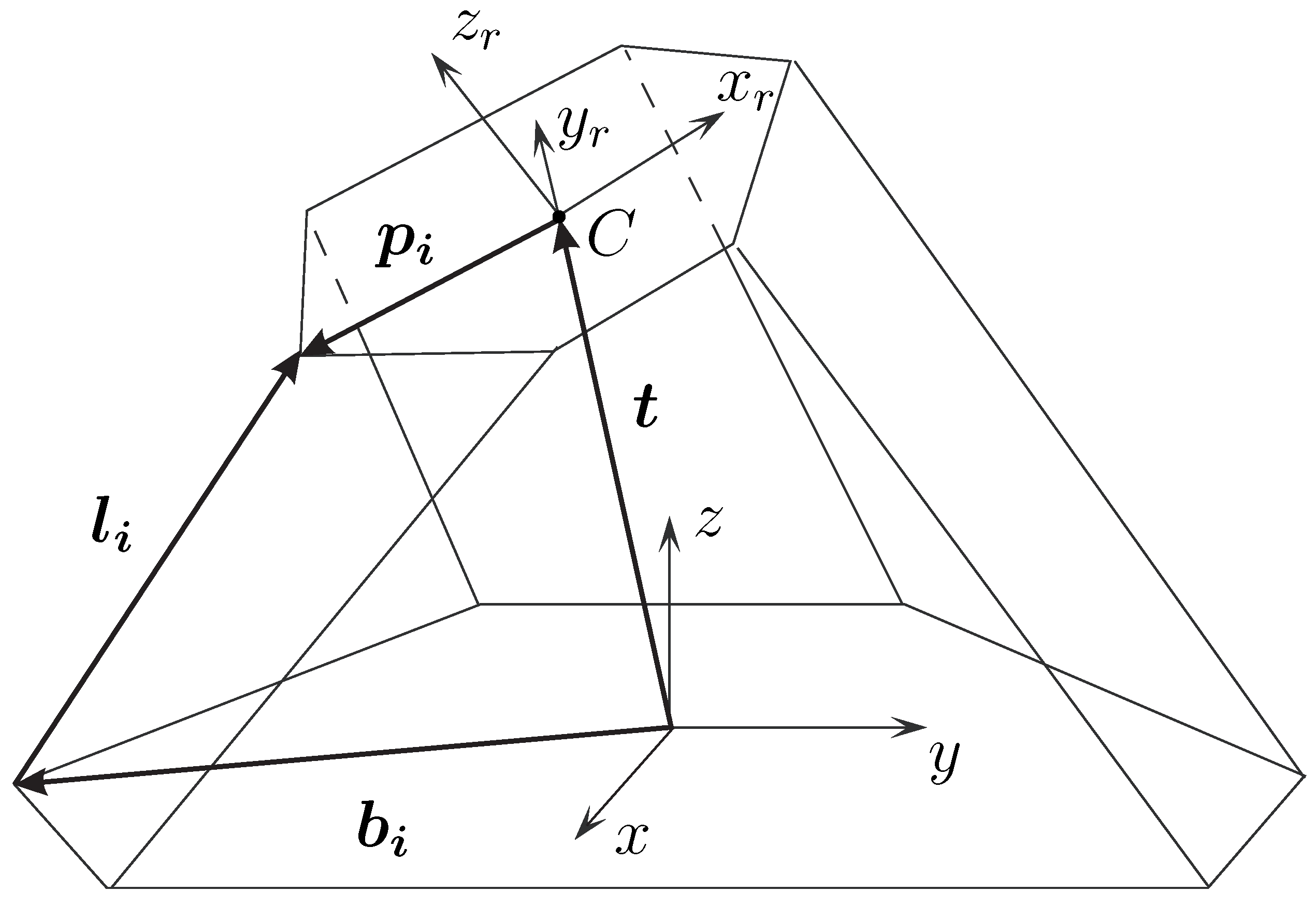
In this section, we summarize the standard Stewart–Gough model used for platforms with spherical joints, which will later serve as a reference when experimentally comparing it to the modified kinematic model developed for our mechanism with preloaded Cardan joints.
Figure 2.
Schematic representation of a Stewart–Gough platform.
Figure 2.
Schematic representation of a Stewart–Gough platform.
For standard Stewart–Gough platforms, the inverse kinematics problem is straightforward [
20]. Given the pose of the moving platform, the leg directions follow from the vector loop equation
where
R is the rotation matrix of the platform,
is the position, and
,
are the fixed leg attachment-point vectors on the base and platform. The leg lengths follow from
In contrast, the direct kinematics problem–computing
from measured leg lengths—is considerably more difficult and may admit multiple solutions [
13]. For obtaining the configuration nearest to a known state, a Newton–Raphson [
21] iteration may be used:
where
are the measured leg lengths and
is the Jacobian
However, this formulation assumes ideal spherical joints and therefore cannot be applied to our platform, which incorporates twelve preloaded Cardan joints. In this case, the leg direction vectors in (
1) are insufficient because the rotational axes of the joints are offset and do not intersect. The kinematics must instead be expressed through homogeneous transformations, as described next.
4. Kinematics of Stewart–Gough Platform with Preloaded Cardan Joints
The procedure presented here constitutes a modification of the algorithm introduced in
Section 3, for which two closely related variants are proposed. In the Cardan-joint-aware model, the direct kinematics is obtained by solving the full set of 72 scalar equations defined by Equation
5, whereas the Optimized Cardan-joint-aware model reduces the number of required equations from 72 to 36 by enforcing only the subset in Equation
11, thereby significantly decreasing the computational load (see Figure 6). Both formulations are mathematically equivalent and converge to the same solution for a given set of encoder readings; consequently, their numerical accuracy was not compared separately, and the analysis focuses solely on differences in computational efficiency.
Each leg of the hexapod mechanism is described by two homogeneous transformations. The platform side transformation
, and the leg-side transformation
obtained from the Denavit–Hartenberg chain (see
Figure 3 for additional explanation of variables in the Denavit–Hartenberg chain).
Starting from the full Cardan-joint-aware model defined by equation
5, a more efficient formulation is obtained by comparing rotations using a minimal three-parameter rotation error vector (eqation
8) and translations using a three-dimensional difference vector (eqation
10). For each leg, we define the relative transformation:
A valid configuration satisfies
Let the rotation and translation parts of
and
be denoted by
and
Matching translations requires
To compare two rotations, we compute the relative rotation
If the rotations match,
. The rotational mismatch is captured compactly using the skew-symmetric part of
:
This three-element rotation-error vector in the Optimized Cardan-joint-aware model replaces the nine scalar equations that would otherwise arise from directly equating
and
. For each leg, we thus obtain three translational constraints and three rotational constraints, yielding a total of six scalar equations per leg and, for six legs,
nonlinear equations. We collect these constraints for leg
i as
4.1. Direct Kinematics
In the direct kinematic problem, the measured leg lengths
are known, while the platform pose
and all internal Cardan-joint angles are unknown. For each leg, its DH transformation
depends on five joint variables, denoted as
We collect all unknowns into
The system of nonlinear equations
thus consists of 36 scalar equations and 36 unknowns. Although the corresponding Jacobian
is square, its conditioning can deteriorate significantly during the Newton–Raphson iteration, and it may even become locally rank-deficient. In such cases a direct inversion of
is numerically unreliable or impossible. To improve robustness, we therefore use the Moore–Penrose pseudoinverse
in the Newton update. The pseudoinverse provides a well-defined generalized inverse that remains stable under ill-conditioning and yields the appropriate least-squares correction step, ensuring consistent convergence even when
cannot be safely inverted.
The iteration stops when
with the initial guess
obtained from the previous known configuration of the hexapod and
is the desired maximal error norm.
4.2. Inverse Kinematics
For inverse kinematics, the platform pose
is prescribed, and the unknown variables are the six leg lengths and the Cardan-joint angles:
The constraint equations remain
with the solution again obtained through the Newton–Raphson update
As before, the initial estimate is taken from the most recently known configuration of the hexapod.
An important feature of the proposed method deserves emphasis. First, the formulation is capable of solving an
arbitrary selection of unknown variables that constitute the kinematic chain defined in Eq. (
5), rather than being limited to a fixed set of joint coordinates during the calculation of inverse and direct kinematics. Independently of this, the symbolic treatment of the constraint equations and their derivatives allows the method to be applied to hexapods with non-standard leg kinematics and arbitrary top- and bottom-plate geometries. Although this leads to increased computational effort, it results in a unified and general framework suitable for a wide range of Stewart-platform architectures.
5. Experimental Validation
5.1. Experimental Setup
The experimental validation was conducted on a passive hexapod equipped with six LinACE
™ absolute linear encoders embedded in the mechanisms legs. To generate reproducible and spatially diverse test poses, a UR10e collaborative robot [
22] was rigidly mounted to the same support frame as the hexapod. A custom top plate with a tool-changer interface was added to the hexapod, enabling direct mechanical coupling to the UR10e end effector. This arrangement ensured a stable connection while allowing the robot to displace the platform into random poses throughout its workspace.
To obtain independent ground-truth pose measurements, a PrimeX 22 OptiTrack motion-capture system was used [
23]. Six infrared cameras were arranged to cover a compact measurement volume of approximately
, maximizing triangulation accuracy within the region of interest. A rigid marker cluster was mounted on the hexapod’s top plate and tracked at full frame rate. Prior to experimentation, the OptiTrack system was calibrated using the standard wand-calibration procedure, followed by rigid-body alignment between the OptiTrack reference frame and the hexapod base frame. The resulting setup provided sub-millimeter positional accuracy and sub-degree rotational accuracy.
During validation, the UR10e robot moved the top plate of the hexapod to a sequence of randomly generated poses within the workspace. At each pose, three data sources were collected synchronously: the 6-DoF ground-truth pose from OptiTrack, the six leg-extension values from the LinACE encoders, and the robot TCP pose, used solely for motion execution and not for accuracy evaluation. A total of 3000 pose configurations were recorded.
Two numerical kinematic models were evaluated: the proposed Optimized Cardan-joint-aware model that accounts for the specific preloaded Cardan-joint geometry, and the standard Stewart–Gough formulation based on the spherical-joint assumption[
4,
5]. Both models used the same encoder-derived leg lengths to compute platform pose estimates for comparison against the OptiTrack measurements.
5.2. Procedure
Random target configurations were generated by sampling translations within of the workspace center and Euler-angle rotations within . Each candidate pose was validated using inverse kinematics; poses requiring leg lengths outside the mechanical limits were discarded and regenerated.
For each feasible pose, the UR10e robot—attached to the hexapod top plate via the tool-changer interface—manipulated the platform into the corresponding spatial configuration. Once the target pose was reached, the hexapod brakes were engaged to lock the structure. The robot then retracted to avoid occluding the OptiTrack cameras, and all measurements were recorded after a short stabilization interval.
For each of the 3000 valid poses, the encoder readings were processed using both the Optimized Cardan-joint-aware and standard Stewart–Gough models. The resulting pose estimates were stored along with the corresponding OptiTrack reference pose for subsequent accuracy evaluation.
Ground-truth and model-estimated poses were compared using separate metrics for translation and rotation. The translational error was computed as
where
is the OptiTrack position measurement and
is the position estimated by the computational model.
Orientation error was computed using the norm of the rotation-vector representation:
where
is the OptiTrack rotation matrix,
is the estimated rotation, and
denotes the matrix logarithm mapping
to its rotation-vector representation[
21]. This formulation is equivalent to computing the minimal-angle orientation difference.
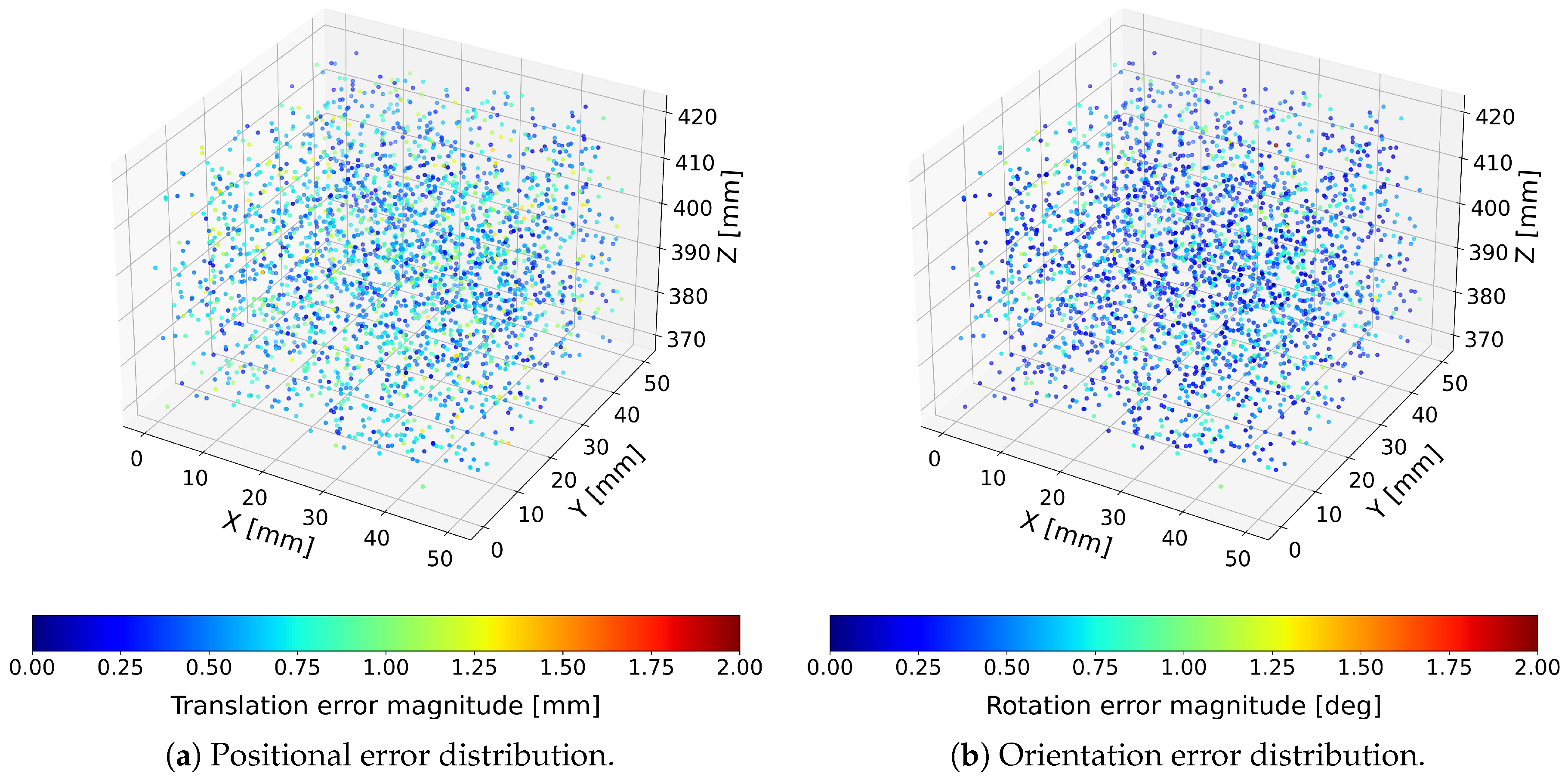
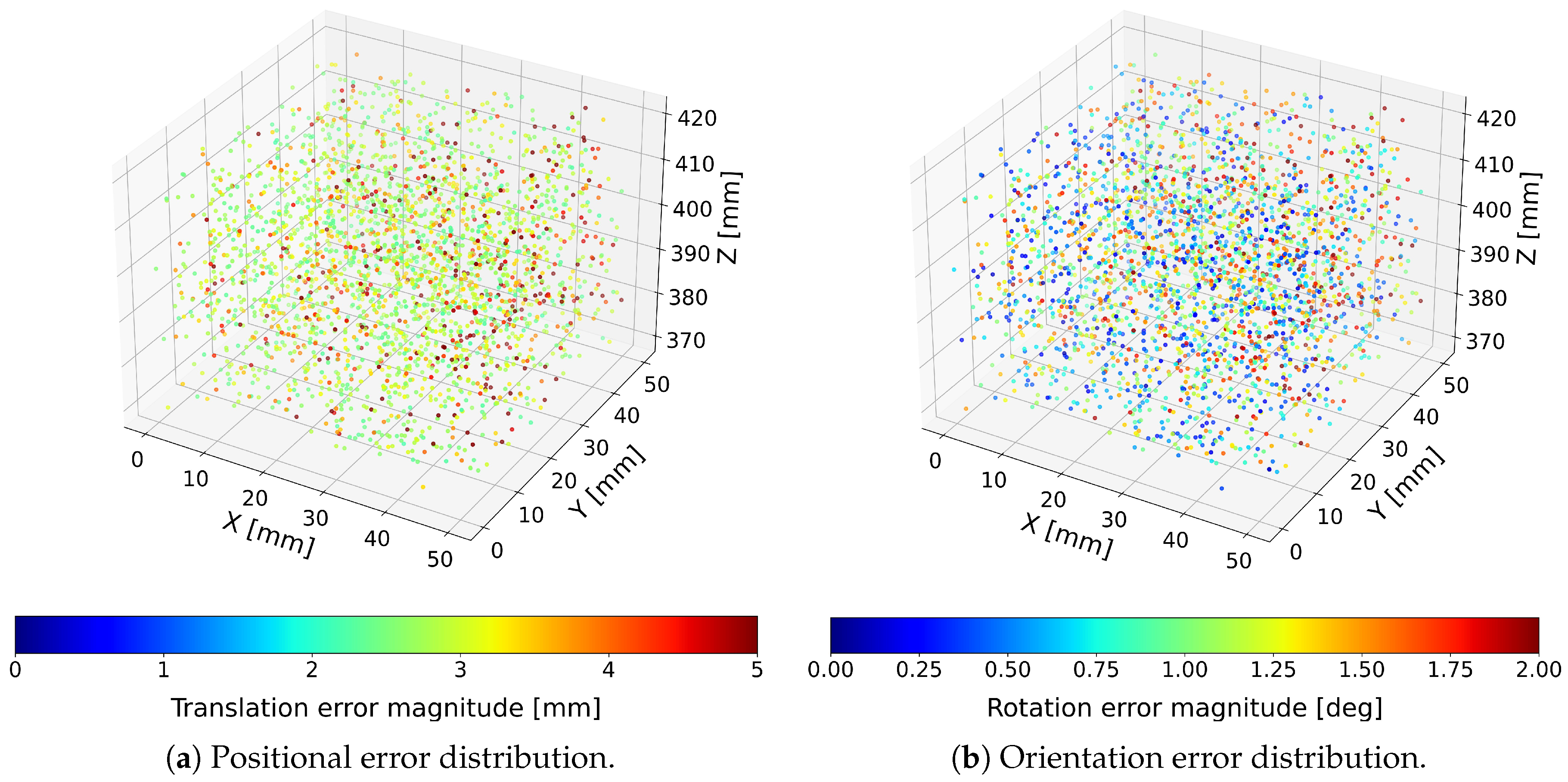
To visualize the spatial distribution of errors across the workspace, both translation and orientation errors were represented as color-encoded point clouds, where each point corresponds to a single tested pose and its color encodes the magnitude of the respective error. Positional and rotational errors were visualized separately due to their different physical units. Results for the proposed Optimized Cardan-joint-aware and standard Stewart–Gough computational models are presented in
Figure 4 and
Figure 5.
Across all 3000 tested configurations, the hexapod achieved mean translational errors below
and mean orientation errors below
when evaluated using the Optimized Cardan-joint-aware model. The afforementioned model consistently outperformed the standard Stewart–Gough model [
11,
12,
18]. These results demonstrate that the integration of absolute linear encoders, combined with a joint-geometry-aware kinematic model, enables sub-millimeter and sub-degree pose estimation, confirming the suitability of the sensor-enhanced hexapod for high-precision industrial fixturing applications[
6,
7]. The corresponding Statistical analyses for the Optimized Cardan-joint-aware model and standard Stewart–Gough model are summarized in
Table 1.
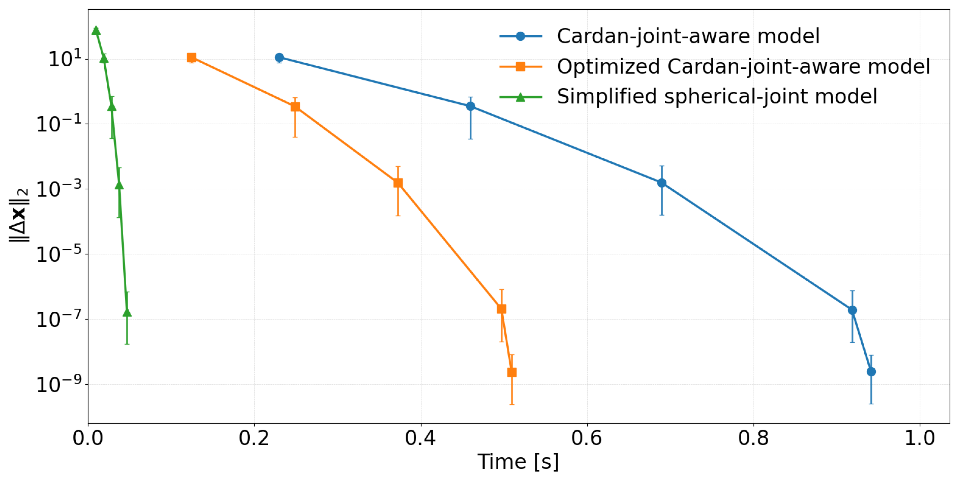
In addition to the workspace error statistics, we analysed the convergence behaviour of the three inverse-kinematic solvers by plotting the parameter-update norm
given in equation
21 as a function of computation time [
21] (see
Figure 6).
All three methods exhibit a nearly linear decrease on the semi-logarithmic scale, indicating stable and well-conditioned Newton iterations (see
Figure 6). The two detailed model variants—the Cardan-joint-aware model, which solves the full equation system in (
5), and the Optimized Cardan-joint-aware model, which solves the reduced systems (
10) and (
11)—are both based on the same matematical model and converge to essentially identical final parameter values. Consequently, the translational and rotational errors they produce are indistinguishable within numerical resolution, and the only practical difference between them is the time required to reach the stopping criterion, with the modified formulation being consistently faster. The reported computation times were obtained on a desktop PC equipped with an AMD Ryzen 9 9950X3D 16-core processor, and all solvers were implemented in Python.
In contrast, the standard Stewart–Gough model converges much more rapidly in time, with its convergence curve shifted far to the left, but the error distributions in the 3D plots reveal substantially larger translation and rotation errors across the workspace. This indicates that, although numerically efficient, the simplified formulation does not reproduce the true mechanism kinematics as accurately as the proposed models. It is therefore best regarded as a fast approximation or an initial-guess generator rather than a replacement for the full kinematic description when high absolute accuracy is required.
Note that the relatively long computation times are primarily a consequence of the symbolic calculation performed using the SymPy package. While this symbolic formulation offers substantial flexibility, particularly the ability to accommodate arbitrary kinematic structures as discussed in
Section 4.2, it also makes the approach too computationally demanding for real-time execution on the Raspberry Pi. As part of our future work, we plan to derive an optimized set of analytical expressions tailored to a specific hexapod configuration, enabling the kinematic calculations to be executed directly on the Raspberry Pi with significantly reduced computational effort.
Finally, we performed a series of tests to demonstrate that the robot can accurately manipulate the hexapod after it has been randomly displaced by a human operator. In this experiment, we used the hexapod equipped with six LinACE™ absolute linear encoders together with a UR10e collaborative robot. Both the robot and the hexapod were fitted with a Destaco QC30–TP30 tool-changer interface, and communication between the two systems was handled through ROS.
During each trial, the human operator manually displaced the hexapod and then engaged its hydro-mechanical brakes to lock its position. The robot then read the pose of the hexapod’s top plate, approached it, and connected the two halves of the clamping mechanism. Achieving this requires sub-millimeter absolute accuracy.
We performed 50 repetitions of the experiment and achieved a 100 % success rate. Videos of the experiment are provided in the supplementary materials.
6. Conclusion
This work experimentally validated a direct kinematics formulation for a passive hexapod fixture equipped with absolute linear encoders embedded in its cylindrical leg joints. Using a UR10e robot to move the mechanism and an OptiTrack PrimeX 22 motion-capture system as an external reference, 3000 randomly selected poses were recorded and evaluated. Across all tested configurations, the proposed Cardan-joint-aware model achieved mean translational errors below 0.62 mm and mean orientation errors below 0.26°, confirming that the combination of encoder instrumentation and an accurate joint-geometry model enables high-precision pose estimation suitable for industrial fixturing and flexible assembly applications.
The choice of an optical measurement system as the ground-truth reference requires some clarification. This system enabled the acquisition of a large number of measurements within a short time, allowing the entire operational workspace of the hexapod to be thoroughly sampled. Although its absolute accuracy is lower than that of high-precision coordinate metrology equipment, it remains sufficient for evaluating performance in the intended industrial, non-human-interaction applications, as well as for robot-assisted manipulation of the hexapod. Using a precision coordinate measuring device would yield higher absolute accuracy and might demonstrate even better agreement with the hexapod’s built-in sensors; however, such increased precision would not meaningfully affect the assessment of the system’s practical usability.
The comparison between the three inverse-kinematics variants showed a clear trade-off between model fidelity and computational cost. The Optimized Cardan-joint-aware model is relatively slow, as all kinematic quantities are represented and manipulated symbolically, but this design choice allows the same model to be used consistently for both direct and inverse kinematics and to handle arbitrary input vectors, with the remaining hexapod parameters being inferred automatically from the symbolic equations. Evaluating this unified symbolic formulation in more detail, including its behavior for different choices of input variables, is an important topic for future work.
The two proposed models, which both incorporate the modified Cardan-joint geometry, converge to essentially identical pose estimates and therefore yield the same translation and rotation error distributions over the workspace. Their only practical difference lies in runtime: the Optimized Cardan-joint-aware model reaches the same convergence threshold significantly faster, making it the preferable choice for real-time or high-throughput implementations. The standard Stewart–Gough model, in contrast, exhibits much smaller computation times and a rapid decay of the Newton update norm, but its translational and rotational errors are substantially larger and show stronger spatial variation. This indicates that the standard Stewart–Gough model does not capture the true mechanism kinematics with sufficient accuracy and is best used as a fast approximation or as an initial-guess generator rather than as a stand-alone solution when absolute accuracy is critical.
Overall, the results demonstrate that a passive hexapod equipped with absolute encoders and driven by a numerically efficient, geometry-aware direct kinematics model can provide reliable 6-DoF pose feedback without resorting to external measurement systems during operation. This makes the concept particularly attractive for reconfigurable fixtures in flexible manufacturing, where rapid changeovers and reproducible positioning are essential. In particular, the ability to reconstruct the platform pose solely from internal encoder measurements is a key enabling technology for human–robot collaboration: any manual repositioning of the hexapod by an operator would otherwise be unobservable and therefore unusable by the robot controller in the absence of such a feedback system. Future work will focus on extending the approach to dynamic loading conditions, studying long-term stability under thermal and mechanical drift, and exploring alternative high-level, task-oriented optimization criteria that enable optimal changeover from one workpiece to another. Moreover, we will derive an optimized set of analytical expressions tailored to a specific hexapod configuration, enabling the kinematic calculations to be executed directly on the Raspberry Pi.
Conflicts of Interest
The authors declare no conflict of interest.
References
- Koren, Y.; Shpitalni, M. Design of reconfigurable manufacturing systems. Journal of Manufacturing Systems 2010, 29, 130–141. [Google Scholar] [CrossRef]
- Gameros, A.; Lowth, S.; Axinte, D.; Nagy-Sochacki, A.; Craig, O.; Siller, H.R. State-of-the-art in fixture systems for the manufacture and assembly of rigid components: A review. International Journal of Machine Tools and Manufacture 2017, 123, 1–21. [Google Scholar] [CrossRef]
- Gough, V.E.; Whitehall, S.G. Universal Tyre Test Machine. In Proceedings of the Proceedings of the 9th International Technical Congress FISITA, 1962, pp. 117–137.
- Stewart, D. A Platform with Six Degrees of Freedom. Proceedings of the Institution of Mechanical Engineers 1965, 180, 371–386. [Google Scholar] [CrossRef]
- Dasgupta, B.; Mruthyunjaya, T.S. The Stewart Platform Manipulator: A Review. Mechanism and Machine Theory 2000, 35, 15–40. [Google Scholar] [CrossRef]
- Silva, D.; Garrido, J.; Riveiro, E. Stewart Platform Motion Control Automation with Industrial Resources to Perform Cycloidal and Oceanic Wave Trajectories. Machines 2022, 10, 711. [Google Scholar] [CrossRef]
- Engblom, C. Evaluation of Galil DMC-4080 as a Controller of Stewart Platform. PhD thesis, Lund University, Lund, Sweden, 2014. Master’s thesis, ISRN LUTFD2/TFRT–5946–SE. [Google Scholar]
- Lim, S.J.; et al. Modeling and Simulation of a Stewart-Platform Type Parallel Structure Robot. In Proceedings of the NASA Conference on Space Telerobotics, Pasadena, CA, USA, 1989. [Google Scholar]
- Ono, K.; coauthors. Analysis and Control of a Stewart Platform as Base Motion Compensators. Nonlinear Dynamics 2022, 110, 2283–2304.
- Kovač, I.; Bem, M.; Gašpar, T.; Bevec, R.; Ude, A. Robot Aided Reconfiguration Concept in Assembly. In Proceedings of the Procedia Manufacturing, 2019. [Google Scholar]
- Zhuang, H.; Roth, Z.S. Method for Kinematic Calibration of Stewart Platforms. Journal of Robotic Systems 1993, 10, 391–405. [Google Scholar] [CrossRef]
- Karmakar, S.; Turner, C.J. A Literature Review on Stewart–Gough Platform Calibrations. Journal of Mechanical Design 2024, 146, 1–27. [Google Scholar] [CrossRef]
- Husty, M.; Pernkopf, F. Model of a U-Joint with skew axes. In Proceedings of the Proceedings of the 11th World Congress in Mechanics and Machine Science, Tianjin, China, 2004. [Google Scholar]
- Kovac, I. Cardan Joint. WO 2018/197439 A1, 2018. PCT/EP2018/060387, priority GB 201706520 (25 April 2017).
- Vrhovec, M. Self-Locking Fluidic Clamping Device. US US20230220856A1, jul 2023. Published patent application.
- Dallej, T.; Nubiola, A.; Renaud, M.; et al. Kinematic Calibration of a Gough–Stewart Platform Using an Omnidirectional Camera. In Proceedings of the 2006 IEEE/RSJ International Conference on Intelligent Robots and Systems (IROS), 2006; pp. 2604–2609. [Google Scholar] [CrossRef]
- Fu, L.; Yang, M.; Liu, Z.; Tao, M.; Cai, C.; Huang, H. Stereo Vision-based Kinematic Calibration Method for the Stewart Platforms. Optics Express 2022, 30, 47059–47069. [Google Scholar] [CrossRef] [PubMed]
- Majarena, A.C.; Santolaria, J.; Samper, D.; Aguilar, J.J. An Overview of Kinematic and Calibration Models Using Internal/External Sensors or Constraints to Improve the Behavior of Spatial Parallel Mechanisms. Sensors 2010, 10, 10256–10297. [Google Scholar] [CrossRef] [PubMed]
- Koubaa, A. Robot Operating System (ROS): The Complete Reference (Volume 3), 1st ed.; Springer Publishing Company, Incorporated, 2018. [Google Scholar]
- Lenarčič, J.; Bajd, T.; Stanišić, M.M. Robot Mechanisms; Springer Science+Business Media: Dordrecht, 2013. [Google Scholar]
- Nocedal, J.; Wright, S.J. Numerical Optimization, 2 ed.; Springer: New York, NY, USA, 2006. [Google Scholar] [CrossRef]
- Universal Robots A/S. UR10e Technical Specifications. Product datasheet, 2023. Available online: https://www.universal-robots.com/products/UR10e (accessed on 25 Nov 2025).
- NaturalPoint, Inc. PrimeX 22 Motion Capture Camera. Product page, 2023. Available online: https://optitrack.com/cameras/primex-22/ (accessed on 25 Nov 2025).
|
Disclaimer/Publisher’s Note: The statements, opinions and data contained in all publications are solely those of the individual author(s) and contributor(s) and not of MDPI and/or the editor(s). MDPI and/or the editor(s) disclaim responsibility for any injury to people or property resulting from any ideas, methods, instructions or products referred to in the content. |
© 2025 by the authors. Licensee MDPI, Basel, Switzerland. This article is an open access article distributed under the terms and conditions of the Creative Commons Attribution (CC BY) license (http://creativecommons.org/licenses/by/4.0/).