
Submitted:
09 October 2025
Posted:
10 October 2025
You are already at the latest version
Abstract
Material extrusion is a widely employed additive manufacturing technique with the functional capability of fabricating solid objects or cellular structures by depositing molten thermoplastic material in successive layers according to the designed path of deposition beads. Carbon fiber sandwich composites are advanced structures, ideal in applications that require high strength and stiffness, and low weight. In the present work, sandwich composites consisting of a carbon fiber-reinforced polyamide core—3D printed with a cubic pattern at 50% infill density—and carbon fiber fabric skin, were fabricated using the hand lay-up method and experimentally investigated. The results showed that the tensile, flexural and impact strength of the sandwich composites increased by 64.5%, 24.5% and 69.0% respectively, compared to unreinforced 3D printed specimens with 50% infill density, and by 24.3%, 18.8% and 56.3% respectively, compared to unreinforced 3D printed specimens with 100% infill density. In addition, a reduction in the water absorption and the density of the sandwich composites was observed. Similar results were obtained for sandwich composites with one additional internal CFF layer. This work demonstrates that this specific combination of materials and manufacturing processes can be successfully employed for lightweight, water-resistant carbon fiber sandwich structures with improved mechanical strength.
Keywords:
sandwich composites
; carbon fiber fabric
; 3D-printed core
; fused deposition modeling
; PAHT-CF
; infill pattern
; mechanical strength
; hardness
; water absorbance
1. Introduction
Carbon fiber sandwich structures have been extensively used in automotive, aerospace, construction, energy and shipbuilding industries due to their low specific weight, high strength-to-weight ratio, enhanced bending stiffness, good energy absorption and corrosion resistance [1-3]. Their basic form consists of a thick, low-density core and a thin, high-strength carbon fiber-reinforced polymer (CFRP) skin firmly bonded to the outer surfaces of the core. The advanced properties of carbon fiber sandwich composites are mainly attributed to the high mechanical strength of the CFRP skin, as well as the high shear and compressive strength of the core and its ability to support the skin and prevent its buckling [4]. The properties of CFRP are highly dependent on fiber orientation, fiber volume fraction, and fiber–matrix bonding. CFRPs exhibit high specific strength and stiffness, low thermal expansion, excellent fatigue resistance, and corrosion resistance. However, they are relatively brittle compared to metals and can be sensitive to impact damage, leading to microcracking or delamination. Manufacturing techniques for CFRP composites vary depending on application requirements and cost considerations. These processes range from simpler methods, such as hand lay-up and vacuum bagging, to more advanced techniques, including vacuum infusion and compression molding. Such methods are employed not only to fabricate the CFRP skins with the desired structural properties but also to integrate them effectively with the core material, thereby producing high-performance sandwich composites. The core can be manufactured in various forms, including porous structures made of foam or balsa wood, corrugated structures with a wave-like pattern, auxetic cellular structures characterized by a negative Poisson's ratio, and lattice truss structures referring to a network of repetitive three-dimensional unit cells of intricate geometry [4-6].
In the last decades, a lot of research has been carried out on the design and manufacturing of cellular cores for sandwich composites. As these cellular cores exhibit complex topology and geometry, they are difficult or impractical to fabricate by conventional subtractive manufacturing. In contrast, the emerging technology of additive manufacturing (AM) and in particular the AM material extrusion technique allows the fabrication of highly complex structures with high accuracy and efficiency [7]. In addition, a wide range of advanced and high-strength materials can be employed, including engineering and high-performance polymers, metal-polymer composites, as well as glass, carbon and aramid-fiber reinforced polymers. 3D-printed parts can serve both as prototypes and end-use functional products, satisfying critical requirements for industries such as shipbuilding [1], automotive [2], aerospace [8] and energy [9].
Fused deposition modelling (FDM) or Fused Filament Fabrication (FFF) is a widely employed material extrusion process that creates objects by depositing fused thermoplastic material in subsequent layers [10]. The feedstock material in the form of a filament is extruded through a nozzle in a semi-molten stage and deposited on subsequent layers onto the building platform. The material is deposited in beads (also referred to as rasters) in the XY plane of the platform following the designed contour - path defined in the 3D printing software. Then, subsequent layers are built on the Z axis until the object is complete. The mechanical properties as well as quality (i.e., geometrical accuracy, surface roughness) of the 3D-printed object depend to a considerable extent on the filament material characteristics, such as melt flow rate, crystallization and viscosity, as well as the user-defined printing parameters, including infill pattern, infill density, layer height, raster width, building orientation, printing speed and extrusion temperature [10].
One of the main advantages of FDM 3D printing is the operational ease of manufacturing customized cellular core structures of two-dimensional patterns or three-dimensional unit cell geometries. Two-dimensional cellular cores are structures with a repetitive grid pattern in each core layer (also referred to as in-plane porosity) and are usually designed using computer-aided design (CAD) software. Some common two-dimensional core structures include honeycomb, hexagonal, re-entrant, triangular and prismatic [7,11]. Three-dimensional lattice cores are arrangements of repeated three-dimensional unit cells, such as octet, octahedral, pyramidal, X-type, Y-type, gyroid, diamond, Kagome, and others [7,11]. These porous structures can either be strut-based or surface-based, and their design is usually performed using mathematical algorithms and specialized software to create triple periodic minimum surfaces (TPMS) topologies [12].
A less complicated procedure to create cellular cores, which eliminates the extensive design and modelling process, is the determination of the infill pattern of the core structure directly in the 3D printing slicing software. Recent developments in advanced slicing software allow the design of intricate infill geometry by specifying parameters including infill density, infill line spacing, infill layer thickness, gradual infill step height and localized infill variations [13]. Infill patterns can be generated as two-dimensional grid pattern (e.g., lines (or rectilinear), triangles (or triangular), zig zag, concentric, tri-hexagonal), or as a network of three-dimensional unit cells (e.g., cubic, gyroid, cubic subdivision, cross 3D, octet, 3D honeycomb) [14]. In the first case, the beads are deposited according to a two-dimensional pattern which is identical in each layer in the XY plane, whereas in the second case, three-dimensional unit cell shapes are created in the infill, and the deposition path of the beads varies in each layer [15-17].
The infill pattern plays a crucial role in determining the stiffness, strength and weight of the 3D-printed core. The maximum strength of a 3D-printed object is generally achieved when the beads are aligned with the direction of the applied loads (e.g., compression, tension, or shear) [18]. In the case of applications with loads that cause multidirectional stress, the infill pattern must ensure uniform distribution of strength in all directions. To achieve this, either three-dimensional infill patterns or two-dimensional patterns that change the direction of deposition in subsequent layers, would be more suitable [14].
In addition to the infill pattern, the infill density which determines the percentage of filling material in the inner volume is also an important factor that affects the strength and stiffness of the 3D-printed part [19,20], as well as the printing time, the amount of material used and the cost of the filament. An optimal combination of infill pattern and infill density for the core can lead to lightweight structures and material savings, while the use of high-strength materials, such as carbon fiber-reinforced polymers or polymer/carbon nanotube composites, can further enhance the strength and structural integrity of the core.
In the present work, sandwich composites that combine a high temperature carbon fiber-reinforced polyamide (PAHT-CF) core and carbon fiber fabric (CFF) skin have been fabricated. The core of the specimens was additively manufactured on a FDM 3D printer with a cubic infill pattern at 50% infill density. Using the hand lay-up method, one layer of carbon fiber fabric impregnated in epoxy resin was bonded on either side of the core. The strength performance of the sandwich composites was then experimentally determined through tensile test, three-point bending test, impact test and hardness measurements and the results were compared to unreinforced PAHT-CF specimens 3D printed at 50% and 100% infill density. In addition, density and water absorption measurement were performed for the unreinforced specimens and the sandwich composites.
This work contributes to the growing body of literature referring to sandwich-type composite materials with a 3D-printed core as follows:
- The proposed sandwich structure, consisting of a carbon fiber fabric/epoxy resin skin and a 3D-printed PAHT-CF core, prepared using the hand lay-up technique, has not yet been experimentally benchmarked in the literature, to the best of the authors’ knowledge.
- A series of different tests have been carried out, including tensile, three-point bending, impact, hardness, density and water absorption tests, providing a comprehensive view of the most important properties, often required in a variety of engineering applications.
- Although the effect of the cubic infill pattern on the properties of FDM 3D-printed samples has been investigated in literature, it has not been studied for PAHT-CF material, to the authors' knowledge. In this work three infill patterns have been examined in terms of their mechanical strength.
- The outcomes of this work highlight the suitability of the proposed sandwich composites as lightweight, high-strength and water-resistant structures for relevant applications.
The rest of the paper is organized as follows: Section 2 provides an overview of the most recent experimental studies on sandwich structures with a 3D-printed core as well as on 3D-printed carbon fiber-reinforced polymers. Section 3 presents the materials, fabrication process and testing methods employed in this work. The results and discussion are presented in Section 4, including, first, the preliminary evaluation of different infill patterns for 3D-printed PAHT-CF specimens and, second, the investigation of the properties for the unreinforced specimens and the sandwich composites. The conclusions are presented in Section 5.
2. Literature Overview
2.1. Sandwich Composites with Additively Manufactured Core
The transition from subtractive manufacturing to additive manufacturing has enabled the fabrication of 3D-printed cellular cores of intricate geometry, which are either intentionally designed as two-dimensional/ three-dimensional cellular structures or by defining the infill pattern parameters directly in the slicing software.
In the literature, extensive research has been conducted on sandwich structures with 3D-printed cores. In many of the recent studies, both the core and the skin are fabricated by additive manufacturing. In particular, the skin can either be 3D printed separately and then bonded to the 3D-printed core using adhesives [21] or can be 3D printed simultaneously with the core in a single AM process eliminating the need for additional joining. The latter can be performed on advanced multi-materials 3D printers with two nozzles. The primary nozzle deposits layers of the thermoplastic material (pure polymer or chopped fiber-reinforced polymer) and the second nozzle creates the skin by depositing layers of continuous fiber-reinforced polymer [22,23] or continuous fibers usually prepreg in thermoplastic resin [24].
In addition to sandwich structures manufactured entirely using 3D printers, experimental studies have also investigated the performance of sandwich composites with 3D-printed core and skin reinforcement, which are manufactured using conventional techniques such as hand lay-up, pressure vacuum bagging or vacuum infusion. Table 1 summarizes the more recent studies in the last five years that refer to conventionally manufactured sandwich structures with 3D-printed core and fiber-reinforced skin, focusing on the hand lay-up technique.
The growing body of the literature demonstrates the interest of researchers and industry in lightweight sandwich structures with improved mechanical performance. Currently, polylactic acid (PLA) is the most commonly used material for core manufacturing due to its biodegradability, cost-effectiveness, and ease of printing. Three-point bending strength, compressive strength and low-velocity impact resistance are the properties of greatest interest for these structures. It is therefore clear that research in this area is still in its early stages. The wide range of materials, from recycled and biodegradable polymers to high-performance polymers, combined with the design freedom of the core structure, offer endless possibilities for combinations in complex sandwich structures. Further research should focus on investigating and/or predicting the performance of sandwich composite structures through the development of optimal combinations of materials and core configurations that could satisfy a wider range of application-specific requirements (e.g., tensile strength, flexural strength, bending stiffness, impact toughness, low-velocity impact performance, temperature resistance, and chemical resistance).
2.2. Effect of Infill Pattern on the Strength of 3D-Printed Carbon Fiber-Reinforced Polymers
The mechanical performance of FDM 3D-printed parts depends significantly on the properties of the filament and the printing parameters set in the slicing software. Even if the same filament is used, different values of the user-defined printing parameters can produce 3D-printed parts with different properties, making it difficult to predict their mechanical strength from the outset. This uncertainty arises, as small variations in the values of the printing parameters can alter the quality of the intermolecular bonding of the thermoplastic material and, consequently, its physical and mechanical properties.
During the printing process, air gaps (also called inter-bead voids or raster gaps) are created between the adjacent deposition beads in each layer. Their size depends on certain printing parameters, such as layer height, raster width, nozzle temperature, printing speed, and infill pattern [41]. It has been reported [18] that reducing the layer height and raster width leads to smaller voids, as the cross-section of the beads is formed into a more rectangular shape with smaller rounded corners. In some cases, a negative air gap is preferred as it provides with overlapping between the beads, ensuring proper adhesion and improving the structural integrity of the 3D-printed part [41,42].
The bonding quality and presence of voids also depend on the nozzle temperature and printing speed, which are key parameters that must be set appropriately and in relation to each other. Studies have shown that setting a high nozzle temperature leads to good material fluidity, better fusion between the adjacent beads, and improved inter-raster bonding strength [10,18]. According to Syrlybayev et al. [43], fusion takes place before the extruded material cools to just below the glass transition temperature, and the longer it remains at a temperature close to the glass transition level (a slow printing speed is required at this stage), the better the bond becomes. However, a very high temperature combined with high printing speed impedes the cooling process, as the material does not have time to cool properly before a new layer is deposited. In such a case, excess overlapping between adjacent beads and layers may occur, resulting in the expansion of the 3D-printed part, geometric deviations and poor surface quality. On the other hand, a low printing temperature can lead to smaller dimensional deviations, but can also cause incomplete melting, the creation of positive air gaps, and poor adhesion between beads and layers.
The influence of printing process parameters on the mechanical performance of FDM 3D-printed parts has been excessively investigated in the literature. However, recent studies have focused on the effect of infill patterns on the mechanical strength of 3D-printed parts made of carbon fiber-reinforced polymers. These studies provide a comparative evaluation of various patterns, with or without varying other printing parameters. Table 2 presents a summary of recent experimental findings on the effect of infill pattern on the mechanical properties of 3D-printed carbon fiber-reinforced polymers. The infill pattern that leads to better mechanical properties is highlighted in bold.
It should be noted that for a given material and fixed printing parameters, a particular infill pattern may provide higher tensile strength compared to other infill configurations, while at the same time this pattern can result in lower strength when the 3D-printed parts are subjected to other loads, i.e., bending, as reported in the work of Pop et al. [48]. In addition, the behavior of the interaction between the infill pattern and other printing parameters, such as infill density, layer height and printing speed, can be quite complex, resulting in different properties. Recent studies have shown that infill density plays a crucial role in the way the infill pattern affects the mechanical properties. In the work of Andreozzi et al. [51], the higher compression strength for PA6 CF-GF samples at 100% infill density is provided by the concentric pattern, while for samples at 50% infill density it is provided by the grid pattern. Similar observations have been reported in the work of Ansari et al. [47], where the highest hardness value for PLA-CF samples at 100% infill density is provided by the grid and triangular pattern, while for samples at 75% infill density it is provided by the tri-hexagonal pattern.
3. Materials and Methods
3.1. Materials
For the additive manufacturing of the unreinforced specimens as well as the core of the sandwich specimens, the 3D printing filament Ultrafuse® PAHT CF15 was utilized. PAHT CF15 is a high temperature PA6-based copolymer with 15% chopped carbon fibers, with advanced mechanical properties, low water absorption, good dimensional stability, good printability, low wrapping and high temperature resistance up to 150 °C [53]. According to the supplier’s technical data sheet, it exhibits a tensile strength of 103.2 MPa (ISO 527), a flexural strength of 160.7 MPa (ISO 178) and an impact strength Izod (unnotched) (ISO 180) of 1.64 J/cm2. For convenience, Ultrafuse® PAHT CF15 will be referred to as PAHT-CF in the rest of the paper.
For the fabrication of the sandwich specimens, the twill weave 3K tow carbon fiber fabric EC3X-208T (208 g/m2) was used as the reinforcement. CFF was impregnated with epoxy resin (PRIMETM 37, d= 1.13 g/cm3) mixed with a slow hardener (AmpregTM 3X) at a ratio of 100:29 by weight and then was attached to the outer surfaces of the core to form the skin of the sandwich structure.
3.2. Fabrication Process
The CAD models of the test specimens were designed using the Autodesk Fusion software. Their dimensions were determined considering the standards for tensile test (ASTM D638), three-point bending test (ASTM D790), and impact test Izod (ISO 180:2019), as illustrated in Figure 1. The core of the sandwich specimens was 3D printed with a reduced thickness by 0.5 mm, considering the thickness of the CFF skin.
For each mechanical test, four categories of specimens were examined, as shown in Figure 2. The first two categories refer to the unreinforced specimens 3D printed at 50% and 100% infill density respectively. The third category refers to sandwich specimens with 3D-printed core and CFF skin reinforcement, while the fourth category refers to sandwich specimens with one additional internal CFF layer. A code has been assigned to each category for convenience.
3.2.1. 3D Printing of the Unreinforced Specimens and the Core
The unreinforced specimens as well as the core of the sandwich specimens were fabricated using an Ultimaker S5 FFF 3D printer. The Ultimaker Cura software was used to set the printing parameters, slice the CAD models, simulate the FDM printing process and automatically generate the G code. Table 3 lists the optimum printing parameters, determined according to the filament supplier’s guidelines, empirical printing tests by the authors [54,55], and printing parameters reported in the literature for the same material [56,57].
The infill density corresponds to the percentage of filling material in the interior of the 3D-printed part which is surrounded by the bottom and top layers and the walls. At 100% infill density, the specimens are solid, capable of withstanding significant loads. For the core, a 50% infill density was assumed appropriate to maintain the mechanical strength of the core while minimizing material usage. The values for other parameters, such as initial layer height, nozzle and build plate temperatures, print speed and initial layer speed, were chosen appropriately to prevent warping and provide good adhesion and high printing accuracy. It is also worth noticing that the core is fully enclosed into a shell which consists of a wall with a thickness of 1.74 mm, and three top and three bottom layers that correspond to a 0.45 mm thickness on either side. The top and bottom layers help to adhere the CFF skin and can reduce the possibility of skin debonding from the core after mechanical testing [58].
Regarding the infill pattern as well as the pattern of the top/bottom layers, a preliminary investigation was performed on the mechanical strength of 3D-printed specimens with different pattern combinations at 100% infill density, as illustrated in Figure 3. These specimens were then evaluated for dimensional accuracy, surface finish and mechanical strength, as described in Section 4.1.
3.2.2. Hand Lay-Up Technique for the Sandwich Specimens
The third category refers to sandwich specimens that consist of the 3D-printed PAHT-CF core at 50% density and the CFF skin. The hand lay-up technique was adopted, and one layer of CFF impregnated with epoxy resin was attached both on the top and bottom surface of the 3D-printed core. Epoxy resin was mixed with the appropriate amount of slow hardener to control the exothermic reaction and prevent the epoxy from hardening too quickly.
The fourth category refers to sandwich specimens that consist of the 3D-printed PAHT-CF core at 50% density, the CFF skin and one additional internal CFF layer. The core was 3D printed in two halves with appropriate thickness, to permit the placement of the CFF layer in the middle. Using the hand lay-up technique, a single CFF layer was impregnated with epoxy resin, placed among the halves and joined them into one piece. Then, one layer of CFF impregnated with epoxy resin was attached on each outer surface to form the CFF skin.
Prior to joining, the surfaces of the printed core were grinded with sandpaper #220 to create roughness on the surface and promote bonding. All sandwich specimens were fixed using clamps, left for seven days to achieve slow curing (Figure 4), and then machined with simple tools to obtain their final shape.
3.3. Testing Methods
Tensile and flexural strength were determined according to ASTM D3039 and D790 standards respectively using a universal machine with a load cell capacity of 10 kN (±0.01 kN accuracy) and a constant crosshead displacement of 2 mm/min. During the test, the load applied to the specimen gradually varied until the failure point of the specimen and the elongation was recorded by a Force-length meter. For the tensile test, a clamping collar was installed on the upper and lower side to hold the specimen, while for the flexural test, a three-point bending fixture was used instead.
The impact strength of the specimens was determined according to ISO 180:2019 using the Izod method at room temperature 20 °C. An Avery–Denison impact testing machine was used, equipped with a 0.975 kg hammer and a built-in dynamometer that records the energy of fracture. The impact speed of the hammer was set to 3.46 m/s. The unnotched specimens were placed in the holder in two different ways: (i) the impact force was applied perpendicular to the top surface of the 3D-printed specimen, and (ii) the impact force was applied perpendicular to the surface on the vertical side of the 3D-printed specimen.
Hardness (Shore-D grade) measurements were carried out according to standard ISO 868:2003. Three surfaces were examined for each specimen: the top surface, the surface on the vertical side, and the bottom surface. Hardness measurements were taken at five different points on each surface.
The density of the specimens was determined according to ASTM D3800 using the buoyancy method at room temperature 19 °C. A single piece of each specimen weighing 3−4 g was initially weighed in air and subsequently fully immersed in ethanol (density 0.79 g/cm3) using a suspension wire. The mass of the samples was measured using an electronic analytical balance of ±0.1 mg accuracy. Three different samples were tested for each category, and the results were obtained by averaging the data. The density of each sample was calculated in g/cm3 using the formula:
where dl is the density of ethanol, m1 is the mass of the wire in air, m2 is the mass of the wire immersed, m3 is the mass of the sample in air, and m4 is the mass of the sample immersed.
di = ((m3 – m1) ∙ dl) / ((m3 – m1) – (m4 – m2)),
The water absorption capability of the specimens was determined according to ASTM D570 at room temperature 19 °C. Single pieces of each specimen were immersed in glass containers with distilled water after being placed in an oven at 100 °C for 1 hour and then dried at room temperature. At various intervals, the pieces were removed from the containers, wiped to remove surface water and weighed using an electronic analytical balance of ±0.1 mg accuracy. The measurements were repeated until no significant change in mass was observed. Three different samples were tested for each category, and the results were obtained by averaging the data. Water absorption per unit volume was calculated in mg/cm3 using the formula:
where m0 is the initial mass of the sample (dry) at time t0, mi is the mass of the sample (immersed) at time ti, and V is the volume of the sample, given by V = m0/d, where d is the density of the sample.
Water absorbed = ((mi – m0) / V) · 1000,
4. Results and Discussion
4.1. Preliminary Evaluation of Infill Patterns for 3D-Printed PAHT-CF Specimens
For a given material, the maximum value of a mechanical property corresponds to a particular combination of printing process parameters, and, in some cases, is significantly affected by the interaction between the infill pattern and other printing process parameters, as mentioned in Section 2.1. In the literature, a limited number of studies [48,54,56,57,59] have investigated the properties of 3D-printed samples employing the same PAHT-CF material used in the present work. The results of these studies depend on the specific 3D printing equipment, the user-defined FDM process parameters, as well as the infill pattern (e.g., triangles, lines, concentric, zigzag, grid), making it difficult to draw direct conclusions about which infill pattern provides superior mechanical properties.
In this context, it was deemed necessary to conduct a preliminary study and investigate the effect of infill pattern on the mechanical strength of 3D-printed PAHT-CF specimens using the experimental processing conditions of the present work. Specimens were 3D printed at 100% infill density to provide maximum strength values, using different pattern combinations including three patterns for the infill (i.e., lines, concentric and cubic) and two patterns for the top/bottom layers (i.e., lines and concentric). Table 4 illustrates the four pattern combinations for the tensile specimen and the corresponding code symbols. The dimensional accuracy, surface finish, tensile strength, elongation at break and impact strength of the 3D-printed specimens were then evaluated.
Regarding the infill, the three specific patterns—lines, concentric, and cubic—were selected due to their distinct characteristics and advantageous applications across various models and requirements. Specifically, the lines pattern is one of the simplest and fastest patterns to print, uses minimal material and reduces filament cost [14]. The concentric pattern takes more time to print; however, it has been reported to exhibit a strong bonding between rasters at 100% infill density [18] and high surface quality [60].
The cubic pattern creates a network of three-dimensional tilted cubes in the infill domain, and provides uniform strength in all directions, which is important in engineering applications [14]. This three-dimensional pattern has recently gained popularity and its effect on the properties of FDM samples has been evaluated in comparison with other infill patterns [16,17,19,45,46,61]. However, the cubic pattern has not, to the authors' knowledge, been investigated to date for 3D-printed PAHT-CF specimens, unlike other patterns, such as grid, lines and triangles [48], triangles [54], concentric and zig zag [56], lines [57], triangles [59] and rectilinear [62].
Regarding the top/bottom layers, the lines and concentric patterns were primarily selected to ensure continuity with the corresponding infill patterns, that is, lines and concentric. Furthermore, these two patterns can provide a smooth surface finish if the material is deposited in beads that are close to each other [13]. For all specimens, a bed temperature of 100 C and a low initial layer speed of 15 mm/s were set to ensure good adhesion of the initial layer to the building platform, minimum edge warpage, and sufficient bonding among the printing beads of the bottom layers.
4.1.1. Mechanical Properties
Figure 5 shows the tensile stress-strain curves obtained for the 3D-printed PAHT-CF specimens at 100% infill density. Two specimens were 3D printed for each pattern combination and tested until failure. For all specimens, the fracture occurred along the length of the gauge.
The average values of the tensile properties are depicted in Table 5. The highest ultimate tensile strength was obtained for the Concentric/Concentric specimens (P100OO), i.e., 127.8 MPa, followed by the Cubic/Concentric specimens (P100CO), i.e., 117.3 MPa. Regarding elongation at break, the higher value was calculated for the P100OO specimens, followed by P100CL. However, the standard deviation values in %ε indicates that P100CL is more sensitive regarding the printing process, while P100CO is the most consistent for FDM 3D printing in terms of repeatability. The higher tensile strength of P100OO specimens was expected, as the tensile load is applied along with the larger dimension of the 3D-printed specimen, which is also the direction of the deposited beads (X-axis) in the concentric pattern. The higher elongation of P100OO specimens can also be explained, since strain depends on the orientation of the beads (raster angle) and is greater when the raster direction is consistent with the X-axis [63]. Unlike the concentric pattern, in the lines and cubic pattern the beads are deposited at 45o/135o raster angles, resulting in specimens with lower tensile strength.
As observed in Table 5, the tensile strength for the PAHT-CF specimens at 100% infill density was found to be close to the value specified by the supplier (i.e., 103.2 MPa according to ISO 527), as well as to values reported in similar experimental studies [54,56]. These small variations are likely due to the specific printing parameters used in this experimental work, which influence the mechanical strength of the specimens.
Impact strength was calculated as the absorbed energy per unit cross-sectional area of the specimens, when the impact force was applied vertically to the top surface (face-up) and vertically to the side surface (side) of the 3D-printed specimens. Figure 6 shows the direction of the impact force on the surfaces of the P100CO impact specimen.
Two unnotched specimens were tested for each pattern combination, and the results were obtained by averaging the data (see Table 5). It can be observed that when the impact force was applied vertically to the top surface, the specimens with the concentric pattern (P100OO) exhibited higher impact strength, i.e., 3.29 J/cm2, than those with the cubic pattern, i.e., 1.99 J/cm2. However, when the impact force was applied vertically to the side of the specimen, no significant difference in impact resistance was observed between the concentric and cubic infill patterns.
One possible explanation about the different impact resistance of the infill patterns relative to the impact force direction, could be the inter-bead and inter-layer bonding. Since the specimen is 3D printed along the Z axis, the adjacent beads are deposited in the XY plane while the layers are built successively along the Z axis. In the lines and concentric patterns, a 10% infill overlap was set, which created negative air gaps between the adjacent beads in each layer. This potentially improved the inter-bead bonding and when the impact force was perpendicular to the top surface, it restricted crack propagation through the top layers and the infill. On the contrary, the beads in the cubic pattern are not deposited in adjacent parallel lines in the XY plane and cannot be overlapped, thus small air gaps are created along each layer, resulting in a slightly lower impact resistance.
When the impact force is perpendicular to the side surface, i.e., perpendicular to the deposition of the 66 layers, it appears that the adhesion between successive layers is not particularly affected by the infill pattern, and therefore no change in impact resistance is observed. It can also be argued that in this case, the bonding between the successive layers depends mainly on the user-defined printing properties, such as layer height, nozzle temperature and print speed, rather than on the infill pattern.
4.1.2. Dimensional Accuracy and Surface Quality
Dimensional accuracy is a crucial factor for applications that require strict tolerances and high functionality. The achievement of the design dimensions mainly depends on the printing process parameters and the respective material behavior during the 3D process, and is affected by 3D printing issues (e.g., warping, shrinkage, inconsistent extrusion). To evaluate the precision of the different pattern combinations, dimensional measurements of the 3D-printed tensile specimens were performed using a micrometer with an accuracy of 0.01 mm. Three measurements were taken for each dimension, and average values are shown in Table 6.
In all cases there was a positive deviation in the size of the 3D-printed specimens in all three dimensions compared to the design dimensions of the CAD model. The Concentric/Concentric combination showed the best dimensional accuracy in both the X and Y axes (length and width of the specimen), followed by the Cubic/Concentric combination with a slight difference which ranges between 0.01 mm and 0.13 mm. Regarding the Z-axis (thickness of the specimen), the Cubic/Concentric and the Concentric/Concentric specimens showed the highest dimensional accuracy. The Lines/Lines and Cubic/Lines pattern combinations showed larger dimensional deviations, leading to the assumption that a higher temperature was developed in the adjacent beads in the top/bottom layers which resulted in enlargement of the specimen size.
Surface quality is also an important indicator of the appearance, quality and functionality of a 3D-printed object. It corresponds to surface imperfections such as visible grooves, grainy texture, small deviations and irregular patterns, and depends directly on the printing process parameters and the material used [64]. As can be seen in Figure 3b, the lines pattern resulted in poor surface quality with noticeable surface imperfections, such as visible grooves and low continuity between the infill and the walls. On the other hand, the concentric pattern provided a uniform and smooth surface finish on the top and bottom surfaces.
4.1.3. Infill Pattern Considerations
Some additional considerations arising from the FDM printing process that could potentially explain the effect of the infill pattern on the quality and mechanical strength of PAHT-CF 3D-printed parts, are as follows:
In the concentric infill pattern (Figure 7a), the deposition path follows the contours of the outer walls from the outside inwards, so each bead has enough time to cool before the next adjacent bead is deposited. In addition, since this two-dimensional pattern is the same at each layer, small air gaps are created between the beads, which extend vertically in the internal volume of the printed object. These vertical passages of voids are prone to crack propagation. Setting the infill overlap to 10% can further improve the inter-bead bonding. The concentric pattern is preferred for axial loads in one direction, particularly parallel to the largest dimension (as in the case of the tensile test specimens).
In the lines infill pattern, the material is deposited in parallel lines that alternate their direction from layer to layer (45° for the first layer and 135° for the next layer). The 45o/135o raster angles provide a more equal distribution of strength in both the X and Y directions, compared to the 0o/90o raster angles. However, in each layer, the length of the deposition lines is very short, and beads are deposited next to each other very quickly, resulting in very little time to cool properly. The high temperature which is developed between adjacent beads can cause a slight enlargement of the 3D-printed object, and this can be strongly observed in objects with a smaller size (for example in the case of the tensile specimens of 3mm thickness and 10mm width).
In the cubic infill pattern (Figure 7b), a network of three-dimensional cubes with one corner facing down, is formed. The deposition path of the beads is different in each layer in the XY plane, resulting in the creation of air gaps at different locations in each layer. In this way, there are no continuous vertical passages of voids along the specimen’s height where a crack could easily propagate. Moreover, the nozzle moves over longer distances along the entire XY plane in a random order, rather than in short parallel lines created in the lines pattern. These longer paths allow for proper cooling of the deposited material, as opposed to the lines pattern. In addition, beads are not parallel to only one stress axis (as occurs in the concentric pattern) but are deposited in 45o/135o raster angles providing uniform stress distribution along the X and Y directions.
Based on the 3D printing results and mechanical tests, the Concentric/Concentric pattern combination resulted in 3D-printed samples with the highest strength and good quality (dimensional accuracy and visual surface finish). However, the concentric pattern is more suitable for structures with a high length-to-width ratio, such as arms or beams, where the tensile load is applied to the longer dimension. Instead, the cubic pattern is considered more suitable to withstand stress in all three axes, which is generalized to most real-world structures, including biomedical devices, automotive components, aerospace components, and marine structures. Regarding the top/bottom layers, the concentric pattern exhibits a smoother surface finish without imperfections, compared to the lines pattern. Under this reasoning, the Cubic/Concentric pattern combination was considered as the most appropriate for 3D printing the unreinforced PAHT-CF specimens, as well as for the core of the sandwich specimens.
4.2. Experimental Investigation of the Performance of the Fabricated Specimens
4.2.1. Density and Water Absorption Measurements
The density was determined according to the standard ASTM D3800 at a room temperature of 19 °C. Three different samples (I, II, III) were tested for each one of the categories P100, P50 and P50R, and the results obtained by averaging the data, are presented in Figure 8.
The density of the unreinforced PAHT-CF specimens at 100% density (P100) was found to be lower than the density of the filament, as specified by the suppliers (i.e., 1.203 g/cm3 according to ISO 1183-1). This variation can be attributed to the porosity created during the printing process, i.e., the voids that are generated between the deposited beads and layers. Also, as expected, a decrease in density of 18.26% (average value) was observed for the P50 unreinforced specimens compared to the P100 unreinforced specimens.
Regarding the sandwich specimens with 3D-printed core and CFF skin (P50R), they exhibited a slight increase in density compared to the P50 specimens. This increase is mainly attributed to the higher density of CFF/epoxy resin which replaced the corresponding volume of PAHT-CF in the P50R specimens, compared to the density of the 50% infilled PAHT-CF material. It is also interesting that the density of the P50R sandwich specimens was found to be even lower than that of the solid P100 specimens. This is a particularly important finding, showing that this specific choice of materials and fabrication technique can provide structures with reduced weight.
Water absorption was determined according to the standard ASTM D3800 for three different samples for each one of the categories P100, P50 and P50R. The typical curves of water absorption expressed as mg H2O per 100 mg are shown in Figure 9. In addition, the average values of water absorbed by the specimens in a 35-days immersion period in distilled water, are reported in Table 7.
Regarding the P100 unreinforced specimens, the water absorption percentage was found to be equal to 3.20% after a 24-hour period (1 day) of immersion in distilled water. This percentage of water absorption is attributed to the presence of voids between the beads and layers created through the 3D printing process. This percentage is consistent with findings in similar experimental works [63], where the water absorption for PA6 specimens emerged in distilled water at room temperature for 24 hours was calculated to be approximately 2.8-2.9%. Regarding the P50 unreinforced specimens, it was found that reducing the infill density by 50% leads to a significant increase in water absorption of 51% after a 35-days immersion period, compared to the P100 specimens, which was expected.
It was also observed that the P50R sandwich specimens exhibited a significantly lower tendency to absorb water compared to the P50 specimens, even though both categories have the same infill density of 50%. It is also interesting that the water absorption tendency of P50R sandwich specimens was found to be even slightly lower than that of the solid P100 specimens at 100% infill density. This is mainly attributed to the replacement of the corresponding volume of PAHT-CF in the specimen with the epoxy resin skin, which exhibits high water resistance. Furthermore, the presence of the CFF skin delays or even prevents the penetration of water into the internal structure (cubic core) of the sandwich specimens. Although reducing the density of the PAHT-CF core by approximately 50% results in substantial air voids and increases the void volume fraction of the composite, the CFF skin reinforcement acts as a protective barrier that impedes moisture penetration, thereby limiting water absorption by the cellular cubic core.
The reduced density and water absorption tendency of the proposed sandwich specimens with 3D-printed PAHT-CF core and CFF skin, may prove beneficial for applications in the water sports and shipbuilding sectors, where lightweight and water-resistant structures are essential. The standard deviation for water absorption measurements regarding the P50R sandwich specimens was also found to be the lowest, indicating good reproducibility of the experimental results.
4.2.2. Hardness Measurements
Hardness measurements were performed on the P100 unreinforced specimens and P50R sandwich specimens according to standard ISO 868:2003. Regarding the unreinforced PAHT-CF specimens, Shore D hardness was measured on three surfaces: (i) the top surface (face-up), (ii) the bottom surface that was in contact with the glass build plate (face-down), and (iii) the surface on the vertical side of the specimen (side). The hardness values at five different points (I to V) on each surface, and the mean values are presented in Table 8.
According to the results for the unreinforced specimens, the hardness measured on the top and bottom surfaces were higher than those measured on the side surface. This indicates a good bonding between the beads in the top/bottom layers, which can be mainly attributed to the concentric pattern and the user-specified overlap parameter. In addition, the mean hardness was found to be higher than the hardness of the PAHT-CF, as specified by the supplier (i.e., 72 according to DIN ISO 7619-1). This variation can also be attributed to the user-defined printing parameters, which enhanced the hardness on the top and bottom surfaces of the 3D-printed specimens. Furthermore, the hardness on the side surface, i.e., perpendicular to the deposition of the 66 layers, was found lower, but close to the supplier’s value, indicating also good inter-layer bonding.
For the P50R sandwich specimens, hardness was measured on two surfaces: (i) the top surface of the CFF skin (face-up) and (ii) the bottom surface (face-down) that was in contact with the glass build plate (face-down). It was found that the CFF skin exhibited higher hardness compared to the PAHT-CF material, corresponding to an increase of 4.6% (on average).
4.2.3. Tensile Strength
Figure 10 depicts the tensile stress versus strain curves of the P100 and P50 unreinforced specimens as well as the P50R sandwich specimens. Five specimens were tested for each category, and the average values were obtained. The results showed that the P50R sandwich specimens exhibited the highest ultimate tensile strength of 145.8 MPa, which corresponds to a remarkable increase of 64.5% compared to the 50% density PA-CF specimens, i.e., 88.6 MPa, and an increase of 24.3% compared to the 100% density PA-CF specimens, i.e., 117.3 MPa. In addition, the P50R sandwich specimens also exhibit the highest elongation at break, indicating a more elastoplastic behavior compared to unreinforced specimens. This typical behavior is primarily attributed to the high tensile strength of the CFF skin, which enables it to carry almost all the in-plane tensile load, allowing the structure to withstand significantly higher loads without failure.
Figure 11 shows the five P50R sandwich specimens after fracture. Except for specimen no. 4, in all other specimens an initial brittle fracture occurred in the CFF skin along the gauge length, while the fractured surface of the PAHT-CF core appeared rough, with sharp peaks located in the porous regions, indicating ductile deformation. This tensile behavior aligns with typical fracture patterns reported in the literature for 3D-printed PAHT-CF samples [56], as well as for sandwich structures with polymer matrix cores and fiber-reinforced polymer skins [36].
The corresponding stress-strain curves for the acceptable specimens (except specimen no. 4) are depicted in Figure 12.
4.2.4. Impact Strength
To determine the impact strength of the P100, P50 and P50R specimens, the impact force was applied in two different ways: (i) perpendicular to the top surface of the specimens (face-up), and (ii) perpendicular to the side surface of the specimens (side). In addition, the R50M sandwich specimens, which consist of the 3D-printed core at 50% density, the CFF skin and one additional internal CFF layer, were also tested with the impact force perpendicular to the top surface (face-up). Three specimens were tested for each category, and the average values are shown in Figure 13.
Figure 13.
Impact strength of the fabricated specimens with respect to the impact force direction.
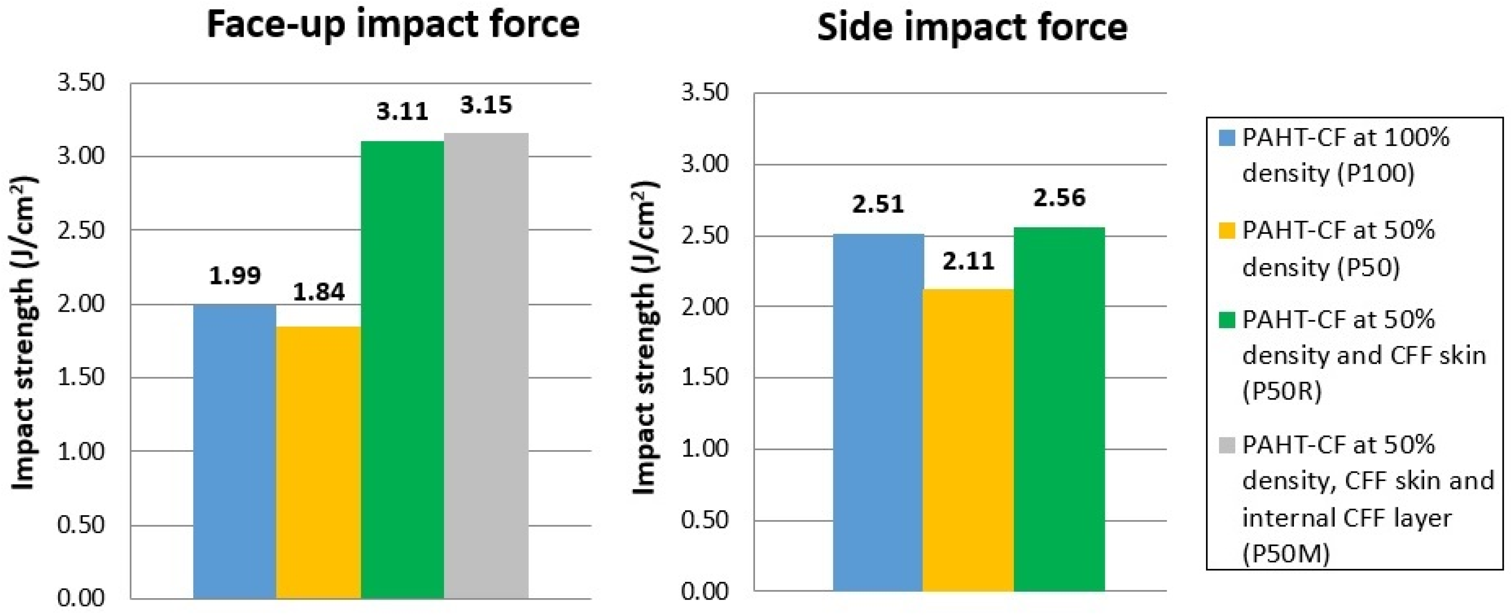
The results indicate that CFF skin reinforcement leads to a significant increase in the impact strength of the sandwich specimens. In particular, when the impact force was applied vertically to the side surface, the CFF skin reinforcement enhanced the impact strength of the P50R sandwich specimens by 21.3% compared to the P50 unreinforced specimens, while no difference was observed with the P100 specimens. On the other hand, when the impact force was applied vertically to the top surface (face-up), the impact strength of the P50R specimens increased by 69.0% compared to the P50 unreinforced specimens, and by 56.3% compared to the P100 unreinforced specimens. A similar impact strength was determined for the P50M sandwich specimens.
It can be clearly observed that although the density of the core has decreased to 50%, the sandwich structure showed improved impact resistance, even higher than that of the P100 specimens. This is mainly attributed to the carbon fiber skin, which distributes the impact load over a larger area and reduces local stress concentration in the core, allowing the absorption of larger amounts of energy thus increasing the overall impact strength.
Figure 14 shows the crack propagation generated during the impact test of the fabricated specimens.
Regarding the P100 and P50 unreinforced specimens, the fracture occurred suddenly with minimal plastic deformation, creating a rough fracture surface with sharp peaks locating in the voids (Figure 14a,b).
Regarding the P50R sandwich specimens, it was observed that the direction of the impact force has a significant effect on the failure mode. Figure 14c,d depicts a P50R specimen subjected to a side impact force. Both the core and skin of the specimen fractured suddenly along the same crack path, resulting in complete failure. For the P50R specimens subjected to a face-up impact force (i.e., perpendicular to the CFF skin), most of them exhibited brittle fracture initiating in the skin and propagating through the core. However, in a few specimens, as shown in Figure 14e,f, the core experienced complete fracture while the CFF skin remained uncracked but detached from the core.
Regarding the P50M sandwich specimens, the internal CFF layer provided additional strength to the sandwich structure. Figure 14g shows a P50M specimen subjected to a face-up impact force, in which both the core and the CFF skin cracked. However, the specimen did not fully separate, as it was held together by the upper CFF skin. Figure 14h depicts another P50M specimens, in which both the lower CFF skin and the internal CFF layer have detached from the core in the region of the specimen located outside the holder of the testing machine. Similarly, the specimen did not fracture completely but was held together by the CFF reinforcement.
4.2.5. Flexural Strength
To determine the flexural strength of the P100, P50 and P50R specimens, the bending load was applied in two different ways: (i) perpendicular to the top surface of the specimens (face-up), and (ii) perpendicular to the side surface of the specimens (side). The R50M sandwich specimens were also tested with the bending load perpendicular to the top surface (face-up). Three specimens were tested for each category, and the average values are shown in Figure 15.
It can be observed that CFF skin reinforcement enhances the flexural behavior of the sandwich specimens and leads to higher flexural strength compared to that of the unreinforced specimens. In particular, when the bending load was applied vertically to the top surface (face-up), the flexural strength of the P50R sandwich specimens increased by 24.5% compared to the P50 unreinforced specimens, and by 18.8% compared to the P100 unreinforced specimens. A similar flexural strength was determined for the P50M sandwich specimens. The enhancement of the flexural strength of the sandwich specimens is mainly attributed to the high modulus of elasticity of the carbon fiber skin, which carries most of the bending loads (tension/compression) and allows the core to resist shear loads. On the other hand, when the bending force was applied vertically to the side surface, the CFF skin reinforcement did not provide any significant increase in flexural strength compared to the unreinforced specimens.
Figure 16 shows the crack propagation generated during the three-point bending test of the specimens.
The fracture of the P100 and P50 unreinforced specimens occurred suddenly, forming a rough fracture surface with sharp peaks, consistent with the typical fracture behavior of PAHT-CF material (Figure 16a).
Regarding the P50R sandwich specimens, the direction of the bending load significantly affected the failure mode of the core and the CFF skin. In the case of side bending load (Figure 16b), both the core and the CFF skin fractured along the same crack propagation path. In the case of face-up bending load (i.e., perpendicular to the CFF skin), some specimens exhibited cracking in both the core and the CFF skin without complete separation (Figure 16c), while in others, the core and upper CFF skin fractured completely, whereas the lower CFF skin detached from the core (Figure 16d).
Regarding the P50M sandwich specimens, the CFF skin and in particular the internal CFF layer provided additional strength and rigidity to the sandwich structure and restricted fracture. In most P50M specimens, the lower CFF skin and the lower half of the core fractured; however, the specimen did not fully separate, as it was held together by the internal CFF layer and the upper CFF skin (Figure 16e). In a limited number of specimens, the lower CFF skin detached from the core (Figure 16f), probably due to insufficient skin-core interface adhesion.
4.2.6. Consideration of Quality-Related Issues
The hand lay-up technique is a cost-effective, widely used conventional manufacturing method for sandwich composites. However, it depends heavily on the user’s experience and quality issues may arise, including skin debonding, undesirable dimensional and geometrical deviations, as well as formation of wrinkles, bubbles, cracks, or other defects.
Figure 17a illustrates the side surface of a P50R specimen. It can be clearly observed that there is a poor adhesion of the resin-impregnated carbon fabric on the lower surface of the 3D-printed core. Similarly, Figure 17b depicts the side surface of a P50M specimen. It can be observed that the CFF skin and the internal CFF layer are not uniform and do not have the same thickness along the length of the specimen. This issue can be attributed to the amount of resin penetrating the fabric, the non-uniform holding of the samples with clamps during the epoxy curing process, or the deformation after unclamping.
Skin debonding often occurs in bending tests of sandwich composites as has been reported in the literature [4,25,26]. Ridlwan et al. [26] fabricated sandwich composites consisting of (a) 3D-printed PC core and carbon fiber skin, and (b) 3D-printed PLA core and glass fiber skin, using the hand lay-up method. During the bending test, the interface strength between the 3D-printed core and the skin could not withstand the stress that occurred, resulting in a debonding failure. According to the authors, when the crack reached the skin, the bending stress was much greater than the shear stress, so the crack changed in the horizontal direction and debonding failure occurred. Alshaer et al. [25] fabricated sandwich beams with CFRP face sheets and 3D-printed PA12 core structures, which underwent face/core debonding during three-point bending tests. Although in plane shear stresses were considered minimal at the core/face interface, skin separation was attributed to the tensile/compression stresses generated at the small areas of poor bonding or small cracks. Also, according to Zhao et al. [4], the higher compressive stress theoretically develops in the middle of the skin, and this location is most prone to debonding. However, since the uniformity at the interface between the skin and the core is not ensured, the location at which debonding occurs is random.
5. Conclusions
The ability of material extrusion additive manufacturing technology to create cellular core geometries combined with the wide range of materials that can be used, enables the manufacture of sandwich-type structures that can satisfy different application-specified requirements. However, the mechanical properties of sandwich composites with a 3D-printed core depend on various parameters, such as the core material, the infill pattern and infill density of the core, the skin material, the core and skin thickness, as well as the efficiency of the 3D printing and hand lay-up process.
In this study, the core of the sandwich composites has been 3D printed at 50% infill density using PAHT-CF material. PAHT-CF is a high-temperature polyamide reinforced with 15% chopped carbon fibers with enhanced mechanical strength. In carbon fiber-reinforced polyamide composites for fused filament fabrication, the carbon fibers are usually homogeneously distributed in the composite and highly oriented along the extrusion flow direction [65]. During the tensile test, the load is effectively transferred to the carbon fibers, when their orientation is along the load direction, and the tensile strength of PAHT-CF is significantly improved compared to unreinforced polyamide. Furthermore, during impact and flexural testing, carbon fibers can effectively prevent crack propagation when their orientation is perpendicular to the direction of the crack development [66].
The proposed 50% infill density for the core undoubtedly increases porosity in the 3D-printed material, and results in lower mechanical strength compared to a solid core 3D printed at 100% infill density. However, by reducing infill density, other process characteristics, such as material cost and printing time, are optimized. Specifically, in this work, 3D printing three samples (tensile, impact, and bending) at 50% infill density corresponded to a 23% reduction in printing time, 16% in filament material, and 24% in material cost, compared to 3D printing at 100% infill density.
Carbon fiber fabric is a high-strength material commonly used for composite structures in the automotive, aerospace and marine industry. The results of this work show that the combination of PAHΤ-CF core and CFF skin reinforcement can lead to sandwich composites with improved mechanical properties, including tensile, flexural, impact strength and hardness. The enhanced mechanical behavior is mainly attributed to the higher strength of the carbon fibers embedded in the polyamide matrix, which also provides increased resistance to crack propagation, reducing the likelihood of failure. In addition, the density and water absorption tendency of the fabricated sandwich specimens were found to be lower than those of the unreinforced specimens. The reduced water absorption is mainly attributed to the water resistance of the epoxy resin and depends also on the thickness of the skin.
Additional findings are summarized as follows:
- The results obtained in the preliminary study in Section 4.1. suggest that the infill pattern has a significant effect on the tensile and impact strength of 3D-printed parts. Among the three examined infill patterns, i.e., lines, concentric and cubic, the concentric pattern should be preferred for structures where tensile strength is a critical parameter, such as arms or beams, while the cubic pattern is more suitable for structures subjected to non-uniform loading.
- PAHT-CF material is easy to print, provided that sufficient print tests have been carried out to ensure the interaction between printing parameters and final properties. Temperature and humidity conditions affect the results, so a closed chamber that maintains temperature during printing and a dry filament to minimize porosity would be desirable.
- Possible solutions regarding the CFF skin detachment include applying epoxy adhesive to the core/skin interface, modifying the epoxy/hardener ratio or the curing time of the epoxy resin, treating the surfaces prior to joining, or using one additional layer of glass or aramid fibers between the skin and the core.
- The proposed fabrication process, which combines 3D printing of the core and hand lay-up technique, is relatively slower than other manufacturing methods for sandwich structures, such as compression molding or advanced 3D printing that integrates the fabrication core and face sheets, so it is more suitable for small-scale or customized products.
- For larger sandwich structures, the limited build volume of FDM 3D printers can be overcome by dividing large-dimensional core structures into many smaller parts. Then, the hand lay-up technique can be used to gradually attach the carbon fiber fabric and join all parts together with epoxy adhesive.
- Future research could include (a) the investigation of the effect of different 3D-printed core structures on the mechanical strength of the sandwich composites, (b) the fabrication of sandwich composites with 3D-printed core and CFF skin using pressure vacuum bagging aiming at reducing geometric deviations and improving the skin/core adhesion, and (c) the attachment of one additional woven roving (fiberglass) layer between the CFF skin and the 3D-printed core to prevent skin detachment.
Utilizing additive manufacturing technology to create the 3D-printed core for carbon fiber sandwich composites can be promising for small-scale lightweight structures with improved strength and stiffness. The unique characteristics of these structures can contribute to improved performance and increased energy efficiency in industries such as aerospace, automotive and shipbuilding. Specifically, for the shipbuilding industry, manufacturing lighter and water-resistant components and structures could lead to faster vessels, reducing the power required for propulsion, and subsequently reducing fuel consumption and harmful emissions. Furthermore, the use of advanced materials, such as carbon fiber-reinforced high performance polymers (HPPs) or stainless steel – polymer composite filaments, for the additive manufacturing of the core and/or the skin, could meet the specific requirements of industrial applications for high-strength products that are resistant to harsh environments.
Author Contributions
Conceptualization, S.D. and I.I.; methodology, S.D. and I.I.; software, G.S.; validation, I.I.; investigation, S.D., I.I. and G.S.; data curation, G.S.; writing—original draft preparation, S.D.; writing—review and editing, S.D., I.I. and D.-N.P. All authors have read and agreed to the published version of the manuscript.
Funding
This research received no external funding.
Data Availability Statement
Data supporting reported results will be available on request.
Conflicts of Interest
The authors declare no conflicts of interest.
References
- Rubino, F.; Nisticò, A.; Tucci, F.; Carlone, P. Marine Application of Fiber Reinforced Composites: A Review. J. Mar. Sci. Eng. 2020, 8, 26. [Google Scholar] [CrossRef]
- Mishra, P.K.; Jagadesh, T. Applications and Challenges of 3D Printed Polymer Composites in the Emerging Domain of Automotive and Aerospace: A Converged Review. J. Inst. Eng. India Series D 2022. [Google Scholar] [CrossRef]
- Hamzat, A.K; Murad, M.S.; Adediran, I.A.; et al. Fiber-reinforced composites for aerospace, energy, and marine applications: an insight into failure mechanisms under chemical, thermal, oxidative, and mechanical load conditions. Adv Compos Hybrid Mater 2025, 8. [Google Scholar] [CrossRef]
- Zhao, T.; Yang, J.; Chen, J.; Guan, S. Review of carbon fiber-reinforced sandwich structures. Polymers and Polymer Composites 2022, 30. [Google Scholar] [CrossRef]
- Feng, Y.; Hao, Q.; Yicong, G.; Hao, Z.; Jianrong, T. Creative design for sandwich structures: A review. Int. J. adv. Robot. Syst. 2020, 17. [Google Scholar] [CrossRef]
- Wu, Y.; & Fang, J.; Wu, C.; Li, C.; Sun, G.; Li, Q. Additively manufactured materials and structures: A state-of-the-art review on their mechanical characteristics and energy absorption. International Journal of Mechanical Sciences 2023, 108102. [Google Scholar] [CrossRef]
- Forés-Garriga, Albert.; Gómez-Gras, G.; Pérez, M.A. Lightweight hybrid composite sandwich structures with additively manufactured cellular cores. Thin-Walled Structures 2023, 191. [Google Scholar] [CrossRef]
- Boado-Cuartero, B.; Pérez-Álvarez, J.; Roibás-Millán, E. Material Characterization of High-Performance Polymers for Additive Manufacturing (AM) in Aerospace Mechanical Design. Aerospace 2024, 11, 748. [Google Scholar] [CrossRef]
- de Leon, A.C.C.; da Silva, I.G.M.; Pangilinan, K.D.; Chen, Q.; Caldona, E.B.; Advincula, R.C. High performance polymers for oil and gas applications. Reactive and Functional Polymers 2021, 162, 104878. [Google Scholar] [CrossRef]
- Krajangsawasdi, N.; Blok, L.G.; Hamerton, I.; Longana, L.; Woods, B.K.S.; Ivanov, D.S. Fused Deposition Modelling of FibreReinforced Polymer Composites: A Parametric Review. J. Compos. Sci. 2021, 5, 29. [Google Scholar] [CrossRef]
- Cuan-Urquizo, E.; Guerra, S.R. Fused Filament Fabrication of cellular, lattice and porous mechanical metamaterials: a review. Virtual and Physical Prototyping 2023, 18. [Google Scholar] [CrossRef]
- Feng, J.; Jianzhong, F.; Yao, X. Triply periodic minimal surface (TPMS) porous structures: From multi-scale design, precise additive manufacturing to multidisciplinary applications. Int. J. Extreme Manuf. 2022, 4. [Google Scholar] [CrossRef]
- UltiMaker Cura Infill settings. Available online: https://support.ultimaker.com/s/article/1667411002588 (accessed on 17 July 2025).
- Wickstrom, S. Mastering 3D Printing Infill Patterns: From Gyroid to Lightning. Available online: https://ultimaker.com/learn/mastering-3d-printing-infill-patterns-from-gyroid-to-lightning/ (accessed on 17 July 2025).
- Ma, Q.; Rejab, M.R.M.; Song, Y.; et al. Effect of infill pattern of polylactide acid (PLA) 3D-printed integral sandwich panels under ballistic impact loading. Materials Today Communications 2024, 38. [Google Scholar] [CrossRef]
- Garg, S.; Singh, A.; Murtaza, Q. Measuring the Impact of Infill Pattern and Infill Density on the Properties of 3D-Printed PLA via FDM. J. Mater. Eng. Perform. 2025. [Google Scholar] [CrossRef]
- Preetish, S.; Harish, S. Effect of Infill Pattern on Flexural Behaviour and Surface Roughness Behaviour of 3D Printed Poly Lactic Acid (PLA) Material. International Journal for Research in Applied Science and Engineering Technology 2024, 12, 1152–1157. [Google Scholar] [CrossRef]
- Akhoundi, B.; Behravesh, A.H. Effect of Filling Pattern on the Tensile and Flexural Mechanical Properties of FDM 3D Printed Products. Exp Mech 2019, 59, 883–897. [Google Scholar] [CrossRef]
- Mishra, P.K.; Senthil, P.; Adarsh, S.; Anoop, M.S. An investigation to study the combined effect of different infill pattern and infill density on the impact strength of 3D printed polylactic acid parts. Composites Communications 2021, 24. [Google Scholar] [CrossRef]
- Rodríguez-Reyna, S.L.; Mata, C.; Díaz-Aguilera, J.H.; Acevedo-Parra, H.R.; Tapia, F. Mechanical properties optimization for PLA, ABS and Nylon + CF manufactured by 3D FDM printing. Materials Today Communications 2022, 33. [Google Scholar] [CrossRef]
- Haldar, A.; Managuli, V.; Rahul, M.; Agarwal, R.; Guan, Z. Compressive Behavior of 3D Printed Sandwich Structures Based on Corrugated Core Design. Materials Today Communications 2020, 26, 10. [Google Scholar] [CrossRef]
- Kamalbabu, P.; Bhanumurthy, R.; Viswanathan, R.; et al. Additive Manufacturing of Honeycomb Core Sandwich Panels: An Evaluation of Flexural Performance. Journal of Physics: Conference Series 2024, 2925. [Google Scholar] [CrossRef]
- Scattareggia Marchese, S.; Epasto, G.; Crupi, V.; Garbatov, Y. Feasibility study on additive-manufactured honeycomb sandwich structural solutions for a Fast Patrol Vessel. Composite Structures 2025, 351, 118607. [Google Scholar] [CrossRef]
- Silva, R.G.; Pavez, G.M. Flexural characteristics of additively manufactured continuous fiber-reinforced honeycomb sandwich structures. Composites Part C: Open Access 2025, 16. [Google Scholar] [CrossRef]
- Alshaer, A.; Harland, D. An investigation of the strength and stiffness of weight-saving sandwich beams with CFRP face sheets and seven 3D printed cores. Composite Structures 2021, 257. [Google Scholar] [CrossRef]
- Ridlwan, M.; Syafi’i, N.M.; Nurgesang, F.A.; Riza, R. 3D Printed Polymer Core and Carbon Fiber Skin Sandwich Composite: An Alternative Material and Process for Electric Vehicles Customization, In Proceedings of 7th International Conference on Electric Vehicular Technology (ICEVT), Bali, Indonesia, 2022, pp. 34-37, 10.1109/ICEVT55516.2022.9924696. [Google Scholar]
- Zoumaki, M.; Mansour, M.T.; Tsongas, K.; Tzetzis, D.; Mansour, G. Mechanical Characterization and Finite Element Analysis of Hierarchical Sandwich Structures with PLA 3D-Printed Core and Composite Maize Starch Biodegradable Skins. J. Compos. Sci. 2022, 6, 118. [Google Scholar] [CrossRef]
- Acanfora, V.; Sellitto, A.; Russo, A.; Zarrelli, M.; Riccio, A. Experimental investigation on 3D printed lightweight sandwich structures for energy absorption aerospace applications. Aerospace Science and Technology 2023, 137, 108276. [Google Scholar] [CrossRef]
- Nur Ainin, F.; Azaman, M.D.; Abdul Majid, M.S.; Ridzuan, M.J.M. Investigating the low-velocity impact behaviour of sandwich composite structures with 3D-printed hexagonal honeycomb core—A review. Funct. Compos. Struct. 2023, 5, 012001. [Google Scholar] [CrossRef]
- Forés-Garriga, A.; Gómez-Gras, G.A.; Pérez, M.A. Lightweight hybrid composite sandwich structures with additively manufactured cellular cores. Thin-Walled Structures 2023, 191. [Google Scholar] [CrossRef]
- Junaedi, H.; Abd El-baky, M.A.; Awd Allah, M.M.; Sebaey, T.A. Mechanical Characteristics of Sandwich Structures with 3D-Printed Bio-Inspired Gyroid Structure Core and Carbon Fiber-Reinforced Polymer Laminate Face-Sheet. Polymers 2024, 16, 1698. [Google Scholar] [CrossRef]
- Francisco, M.B.; Gomes, R.A.; Pereira, J.L.J.; da Cunha, S.S.; Gomes, G.F. High-performance design of auxetic sandwich structures: A multi-objective optimization approach. Mech. Adv. Mater. Struct. 2024, 32(6), 1225–1240. [Google Scholar] [CrossRef]
- Shah, S.; Lee, J.; Altaf, K.; et al. Quasi-static indentation characteristics of foam-filled sandwich composite structures with additively manufactured CFRP and GFRP corrugated cores. J. Sandw. Struct. Mater. 2024, 27, 505–529. [Google Scholar] [CrossRef]
- Stepinac, L.; Galić, J. Preliminary investigation of the large-scale sandwich decks with graded 3D printed auxetic core. J. Sandw. Struct. Mater. 2024, 27, 260–278. [Google Scholar] [CrossRef]
- Abbas, M. Low-velocity impact behavior assessment of 3D printed sandwiched structure with varying infill patterns, M.Sc. Thesis, National University of Sciences & Technology (NUST), Pakistan, 2025. [Google Scholar]
- Azeem, M.; Nasir, M.A. Tensile behavior of sandwich structures using various 3D printed core shapes with polymer matrix composites. Int. J. Adv. Manuf. Tech. 2025, 137, 5665–5682. [Google Scholar] [CrossRef]
- Brejcha, V.; Böhm, M.; Holeček, T.; Jerman, M.; Kobetičová, K.; Burianová, I.; Černý, R.; Pavlík, Z. Comparison of Bending Properties of Sandwich Structures Using Conventional and 3D-Printed Core with Flax Fiber Reinforcement. J. Compos. Sci. 2025, 9, 182. [Google Scholar] [CrossRef]
- Kalaimagal, S.; Vasumathi, M.; Rashia Begum, S.; et al. Evaluation of impact resistance of sustainable sandwich structures with optimized FDM core geometries using low-velocity drop impact tests. Polym Compos. 2025, 1–16. [Google Scholar] [CrossRef]
- Mirzaei, J.; Nouri, N.M.; Nikouei, S. Mechanical characteristics of 3D -printed honeycomb sandwich structures: Effect of skin material and core orientation. Polym Compos 2025. [Google Scholar] [CrossRef]
- Muralidharan, B.; Kanmani Subbu, S.; Ajikumar, A.K.; et al. Experimental and numerical study of three-point bending test in five different FDM 3D printed PLA core with carbon fiber sandwich structures. Engineering Research Express 2025, 7. [Google Scholar] [CrossRef]
- Solomon, I.J.; Sevvel, P.; Gunasekaran, J. A review on the various processing parameters in FDM, Materials Today: Proceedings 2021, 37:509–514. [CrossRef]
- Gonabadi, H.; Hosseini, S.F.; Chen, Y.; et al. Size effects of voids on the mechanical properties of 3D printed parts. Int J Adv Manuf Technol, 5439. [Google Scholar] [CrossRef]
- Syrlybayev, D.; Zharylkassyn, B.; Seisekulova, A.; Akhmetov, M.; Perveen, A.; Talamona, D. Optimisation of Strength Properties of FDM Printed Parts—A Critical Review. Polymers 2021, 13, 1587. [Google Scholar] [CrossRef] [PubMed]
- Naranjo-Lozada, J.; Ahuett-Garza, H.; Pedro Orta-Castañón, P.; et al. Tensile properties and failure behavior of chopped and continuous carbon fiber composites produced by additive manufacturing, Additive Manufacturing 2019, 26:227-241, 10.1016/j.addma.2018.12.020.
- Rao, V.D.P.; Rajiv, P.; Geethika, V. Effect of fused deposition modelling (FDM) process parameters on tensile strength of carbon fibre PLA. Materials Today: Proceedings 2019, 18. [Google Scholar] [CrossRef]
- Ma, Q.; Rejab, R.; Kumar, A.P.; Fu, H.; et al. Effect of infill pattern, density and material type of 3D printed cubic structure under quasi-static loading. Proceedings of the Institution of Mechanical Engineers, Part C: J. Mech. Eng. Sci. 2020, 1:1-19. 10.1177/0954406220971667.
- Ansari, A.A.; Kamil, M. Izod impact and hardness properties of 3D printed lightweight CF-reinforced PLA composites using design of experiment, Int. J. Lightweight Mater. Manuf. 2022, 5. [Google Scholar] [CrossRef]
- Pop, M.A.; Zaharia, S. ; Chicos, L-A.; Lancea, C. et al. Effect of the infill patterns on the mechanical properties of the carbon fiber 3D printed parts. IOP Conference Series: Materials Science and Engineering 2022, 1235(1), 10.1088/1757-899X/1235/1/012006. [Google Scholar]
- Sun, B.; Mubarak, S.; Zhang, G.; Peng, K.; Hu, X.; Zhang, Q.; Wu, L.; Wang, J. Fused-Deposition Modeling 3D Printing of Short-Cut Carbon-Fiber-Reinforced PA6 Composites for Strengthening, Toughening, and Light Weighting. Polymers 2023, 15, 3722. [Google Scholar] [CrossRef]
- Abali, B.E.; Afshar, R.; Khaksar, N.; Segersten, D.; Vedin, T. Damage Behavior in Additive Manufacturing based on Infill Pattern and Density with Carbon Particle Filled PolyLactic Acid (CF-PLA) Polymer Filaments. In State of the Art and Future Trends in Materials Modelling 2. Advanced Structured Materials; Altenbach, H., Öchsner, A. Eds.; Springer, 2024; Volume 200, pp 1–16.
- Andreozzi, M.; Bianchi, I.; Archimede, F.; et al. Effect of infill percentage and pattern on compressive behavior of FDM-printed GF-CF PA6 composites. Conference Material Forming (ESAFORM), Materials Research Proceedings 2024, pp. 283-289, 10.21741/9781644903131-32.
- Hozdić, E.; Hozdić, E. Influence of Infill Structure Shape and Density on the Mechanical Properties of FDM 3D-Printed PETG and PETG+CF Materials. Advanced Technologies & Materials 2024, 49, 15–27. [Google Scholar] [CrossRef]
- Ultrafuse® PAHT CF15 TDS. Available online: https://forward-am.com/wp-content/uploads/2024/10/ Ultrafuse_PAHT_CF15_TDS_EN_v3.5-1.pdf (accessed on 17/07/2025).
- Dimitrellou, S.; Iakovidis, I.; Psarianos, D.R. Mechanical Characterization of Polylactic Acid, Polycarbonate, and Carbon Fiber-Reinforced Polyamide Specimens Fabricated by Fused Deposition Modeling. J. Mater. Eng. Perform. 2024, 33, 3613–3626. [Google Scholar] [CrossRef]
- Dimitrellou, S.; Iakovidis, I.; Stratos, G.; Lemonis, I. Strength performance of carbon fiber sandwich composites with an additively manufactured fiber-reinforced polyamide grid core. Proceedings of 8th International Conference of Engineering Against Failure, Greece, 22-25 June 2025. [Google Scholar]
- Tutar, M. A Comparative Evaluation of the Effects of Manufacturing Parameters on Mechanical Properties of Additively Manufactured PA and CF-Reinforced PA Materials. Polymers 2022, 15. [Google Scholar] [CrossRef] [PubMed]
- Condruz, M.; Paraschiv, A.; Badea, T.; et al. A Study on Mechanical Properties of Low-Cost Thermoplastic-Based Materials for Material Extrusion Additive Manufacturing. Polymers 2023, 15. [Google Scholar] [CrossRef] [PubMed]
- Acanfora, V.; Zarrelli, M.; Riccio, A. Experimental and Numerical Assessment of the Impact behaviour of a Composite Sandwich Panel with a Polymeric honeycomb Core. International Journal of Impact Engineering 2022, 171. [Google Scholar] [CrossRef]
- Prasad, S.; Prakash, S. Experimental investigation of laser texturing on surface roughness and wettability of PAHT CF15 fabricated by fused deposition modeling. Polymer Composites 2024, 46. [Google Scholar] [CrossRef]
- Lalegani Dezaki, M.; Ariffin, M.K.A.M.; Serjouei, A.; Zolfagharian, A.; Hatami, S.; Bodaghi, M. Influence of Infill Patterns Generated by CAD and FDM 3D Printer on Surface Roughness and Tensile Strength Properties. Appl. Sci. 2021, 11, 7272. [Google Scholar] [CrossRef]
- Aloyaydi, B. ; S., Sivasankaran, S.; Al-Areqi, A.M. Investigation of infill-patterns on mechanical response of 3D printed poly-lactic-acid. Polymer Testing 2020, 87. [Google Scholar] [CrossRef]
- Butt, J.; Khan, M.A.A.; Adnan, M.; Mohaghegh, V. Performance Analysis of FFF-Printed Carbon Fiber Composites Subjected to Different Annealing Methods. J. Manuf. Mater. Process. 2024, 8, 252. [Google Scholar] [CrossRef]
- Lay, M.; Thajudin, N.; Abdul, H.; et al. Comparison of physical and mechanical properties of PLA, ABS and nylon 6 fabricated using fused deposition modeling and injection molding. Composites Part B: Engineering 2019, 176. [Google Scholar] [CrossRef]
- Dimitrellou, S.; Strantzali, E.; Iakovidis, I. A decision-making strategy for selection of FDM-based additively manufactured thermoplastics for industrial applications based on material attributes. Sustainable Futures 2025, 9. [Google Scholar] [CrossRef]
- Dul, S. ; Fambri, L; Pegoretti, A. High-Performance Polyamide/Carbon Fiber Composites for Fused Filament Fabrication: Mechanical and Functional Performances. J. Mater. Eng. Perform. 2021, 30:5066–5085. [Google Scholar] [CrossRef]
- Liao, G.; Li, Z. ; Cheng,Y. et al. Materials & Design, 2: 12 composite parts fabricated by fused deposition modeling, Materials & Design 2018, 139, 2018. [Google Scholar] [CrossRef]
Figure 1.
Design dimensions of specimens for (a) tensile test, (b) impact test, and (c) flexural test.
Figure 1.
Design dimensions of specimens for (a) tensile test, (b) impact test, and (c) flexural test.
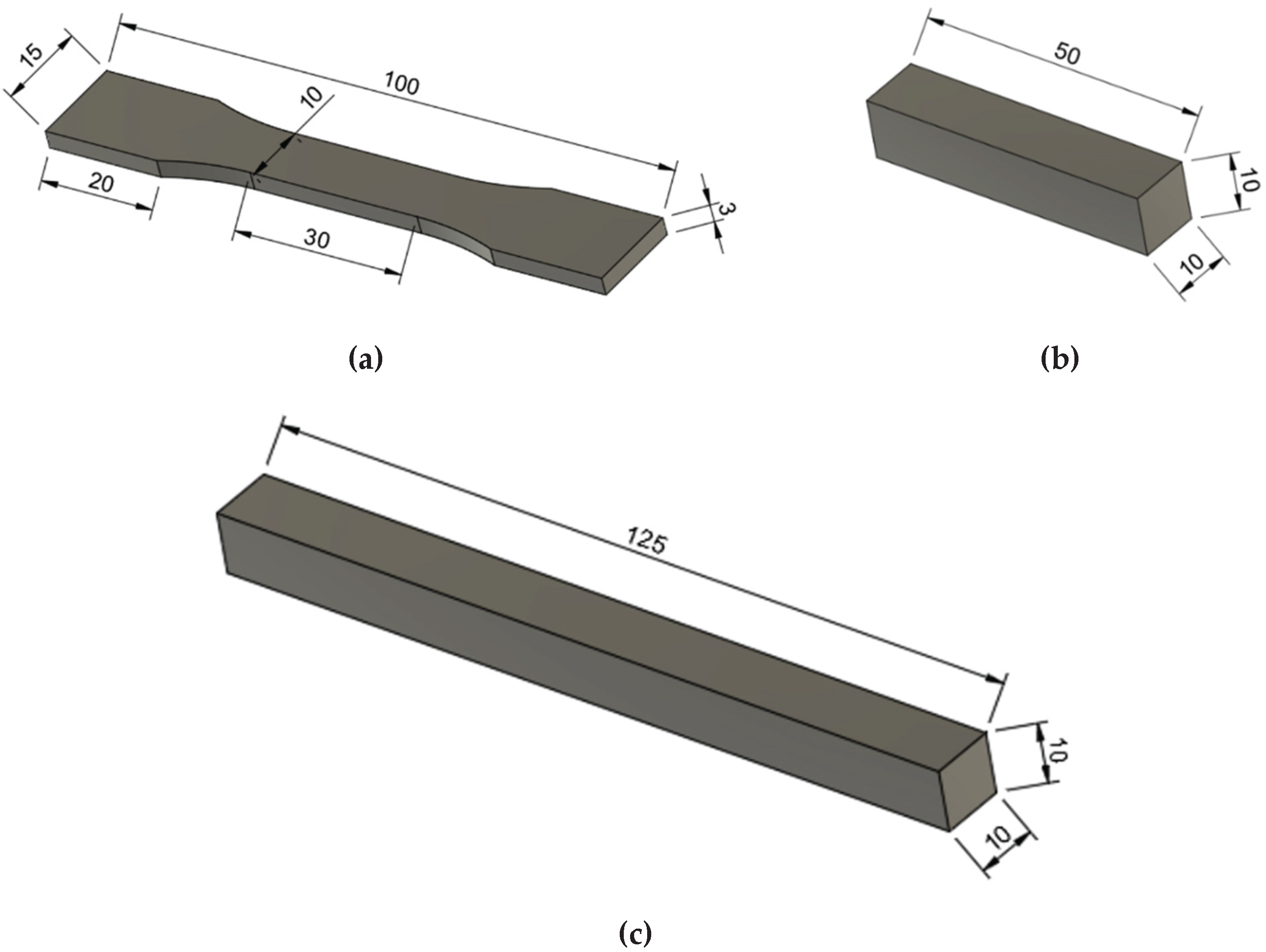
Figure 2.
Illustration of the fabrication process.
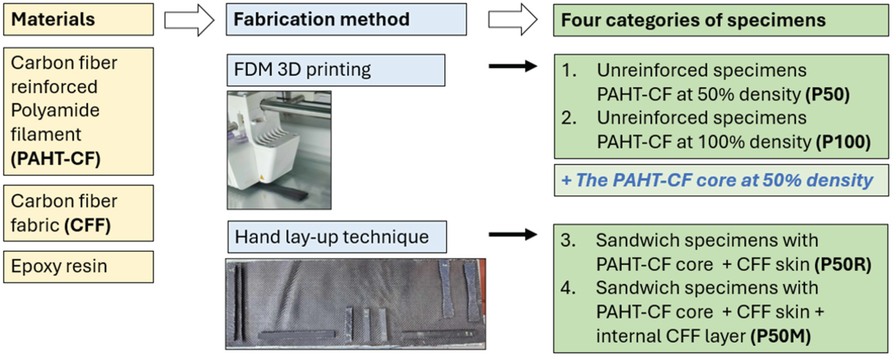
Figure 3.
Tensile test specimens with (a) cubic infill pattern and (b) lines and concentric pattern in top layer.
Figure 3.
Tensile test specimens with (a) cubic infill pattern and (b) lines and concentric pattern in top layer.
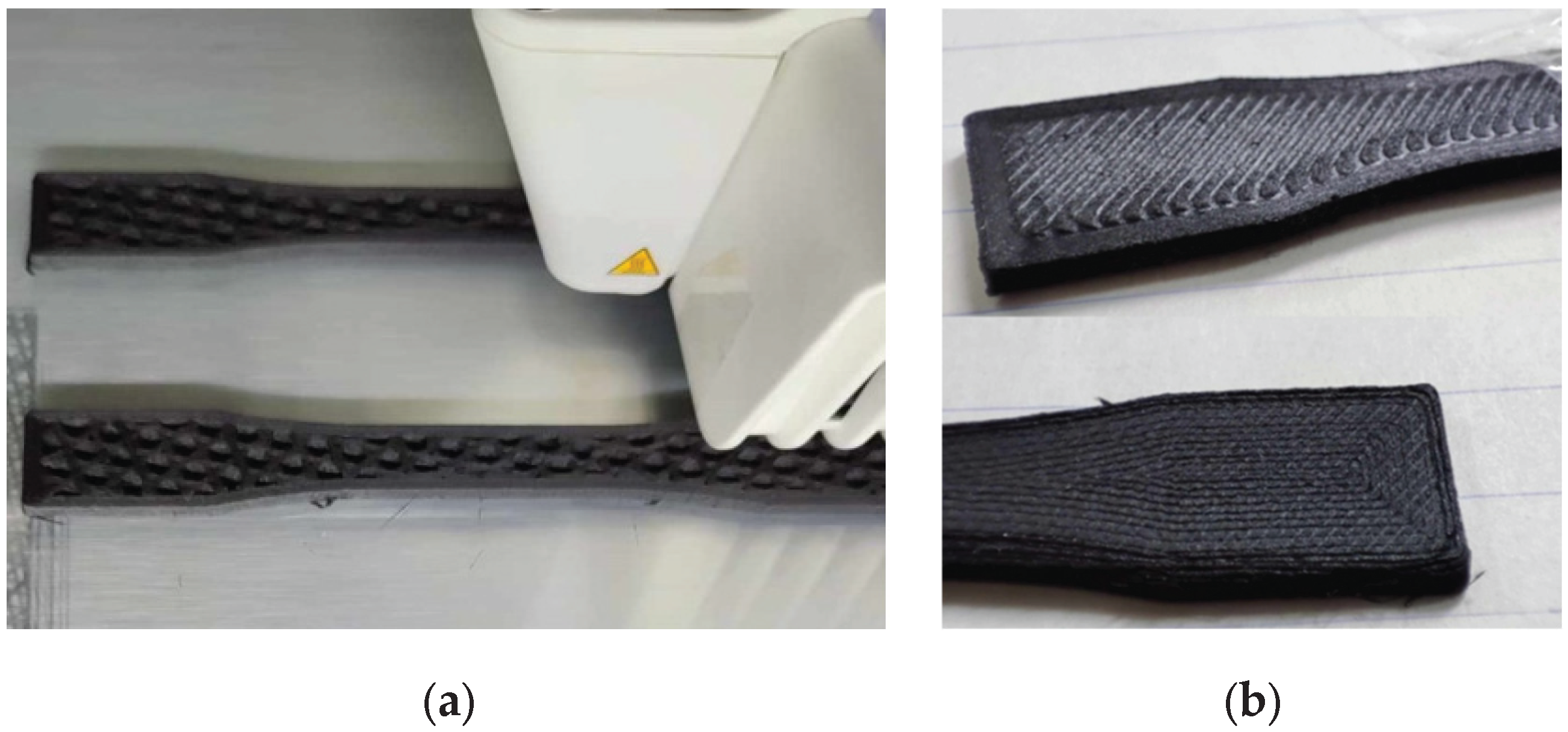
Figure 4.
Slow curing of specimens for (a) tensile test and (b) flexural test.
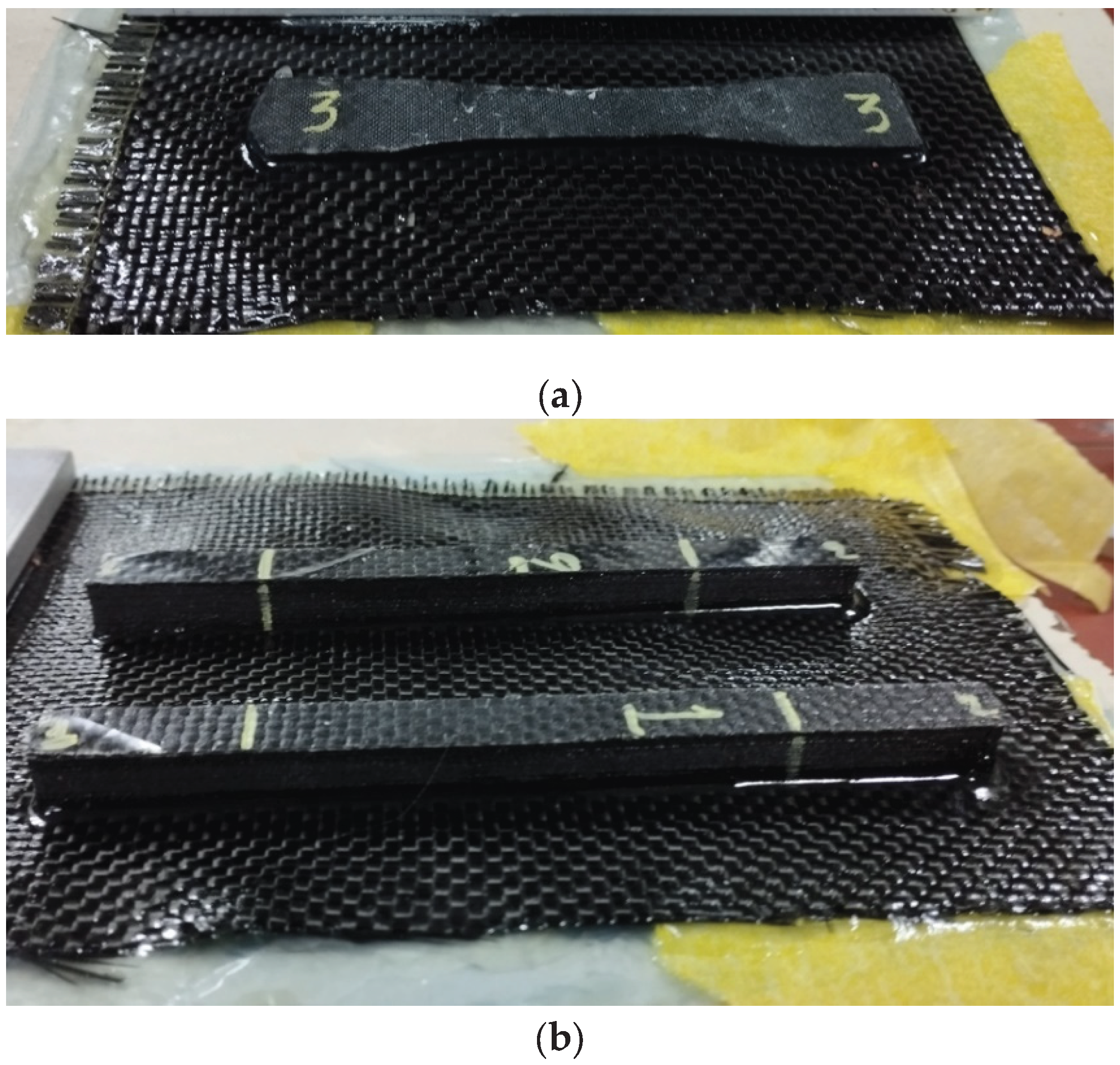
Figure 5.
Stress-strain curves and PAHT-CF specimens after tensile test.
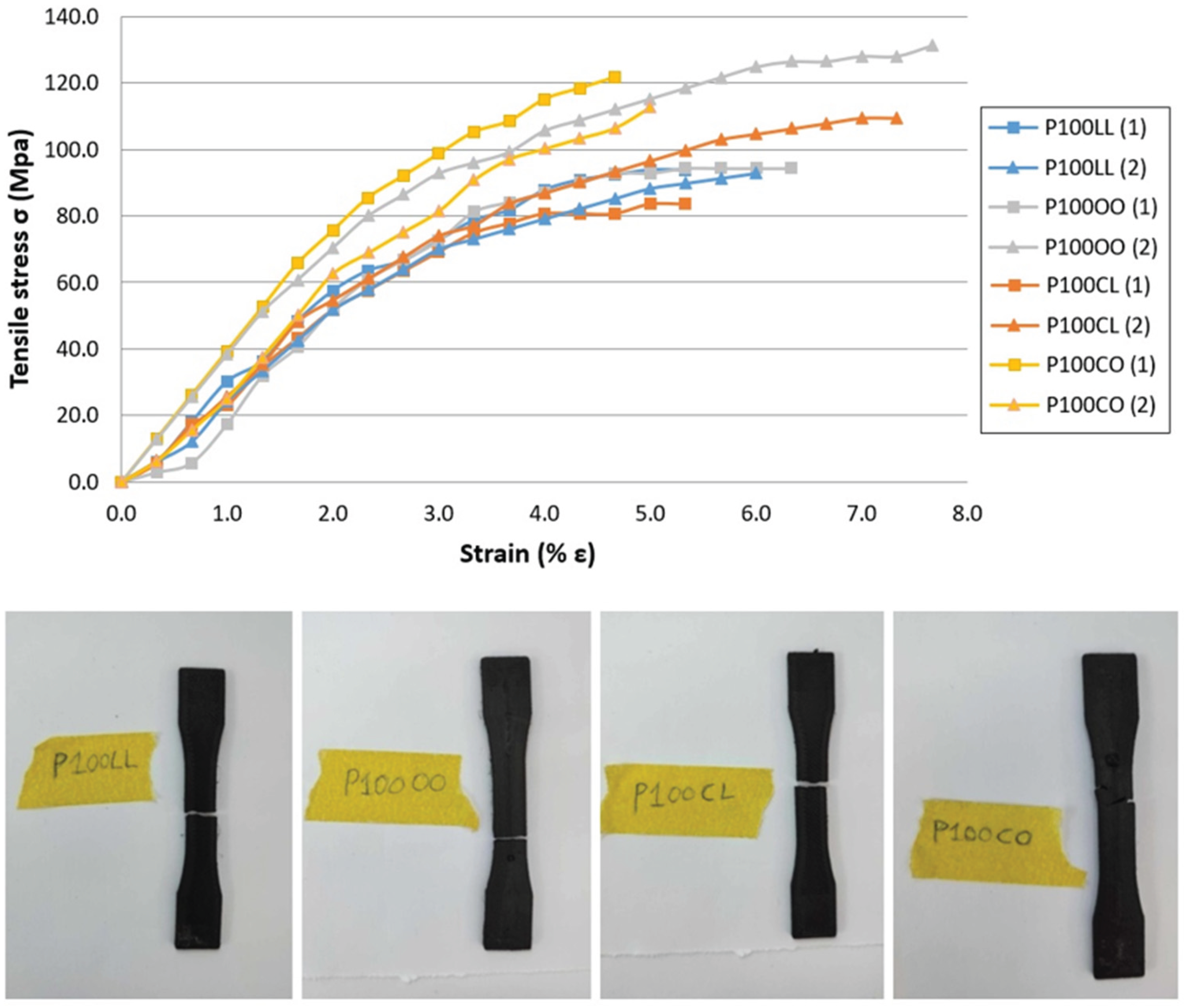
Figure 6.
Direction of impact force for test specimen with cubic pattern. The top layer has been removed to display the infill.
Figure 6.
Direction of impact force for test specimen with cubic pattern. The top layer has been removed to display the infill.
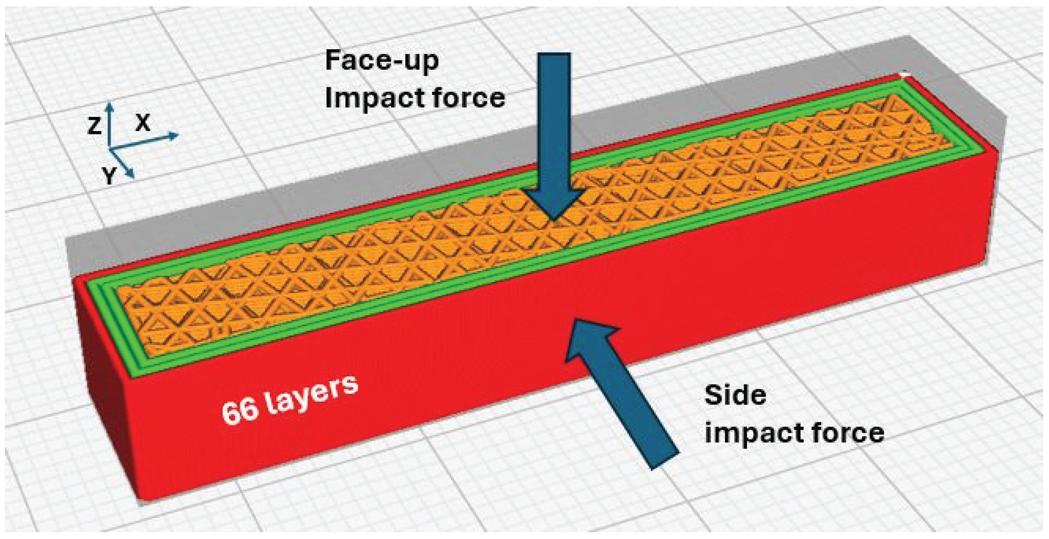
Figure 7.
(a) The concentric infill pattern; (b) The cubic infill pattern. Walls and top/bottom layers have been removed to display the infill.
Figure 7.
(a) The concentric infill pattern; (b) The cubic infill pattern. Walls and top/bottom layers have been removed to display the infill.
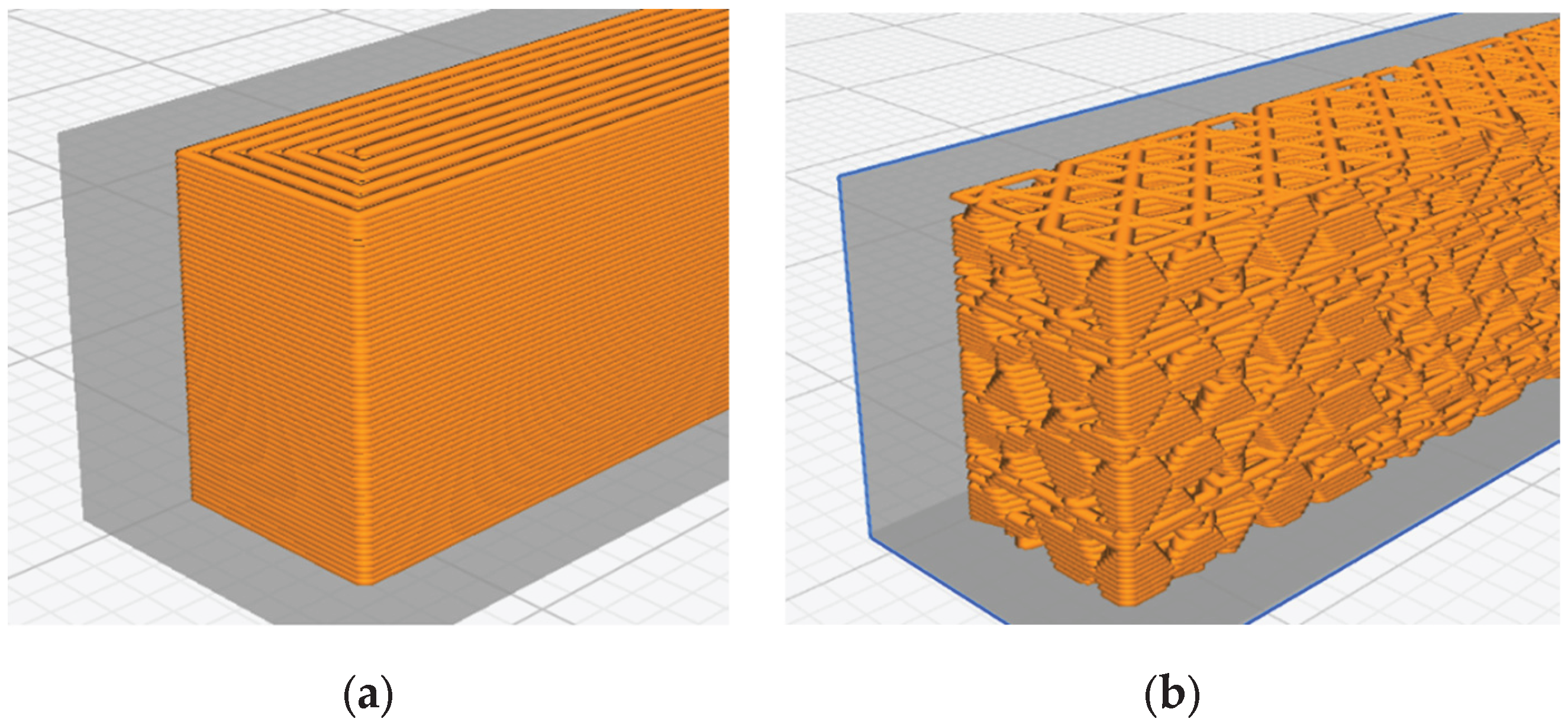
Figure 8.
Density values in g/cm3 for the unreinforced specimens (P100, P50) and the sandwich specimens with 3D-printed core and CFF skin (P50R).
Figure 8.
Density values in g/cm3 for the unreinforced specimens (P100, P50) and the sandwich specimens with 3D-printed core and CFF skin (P50R).
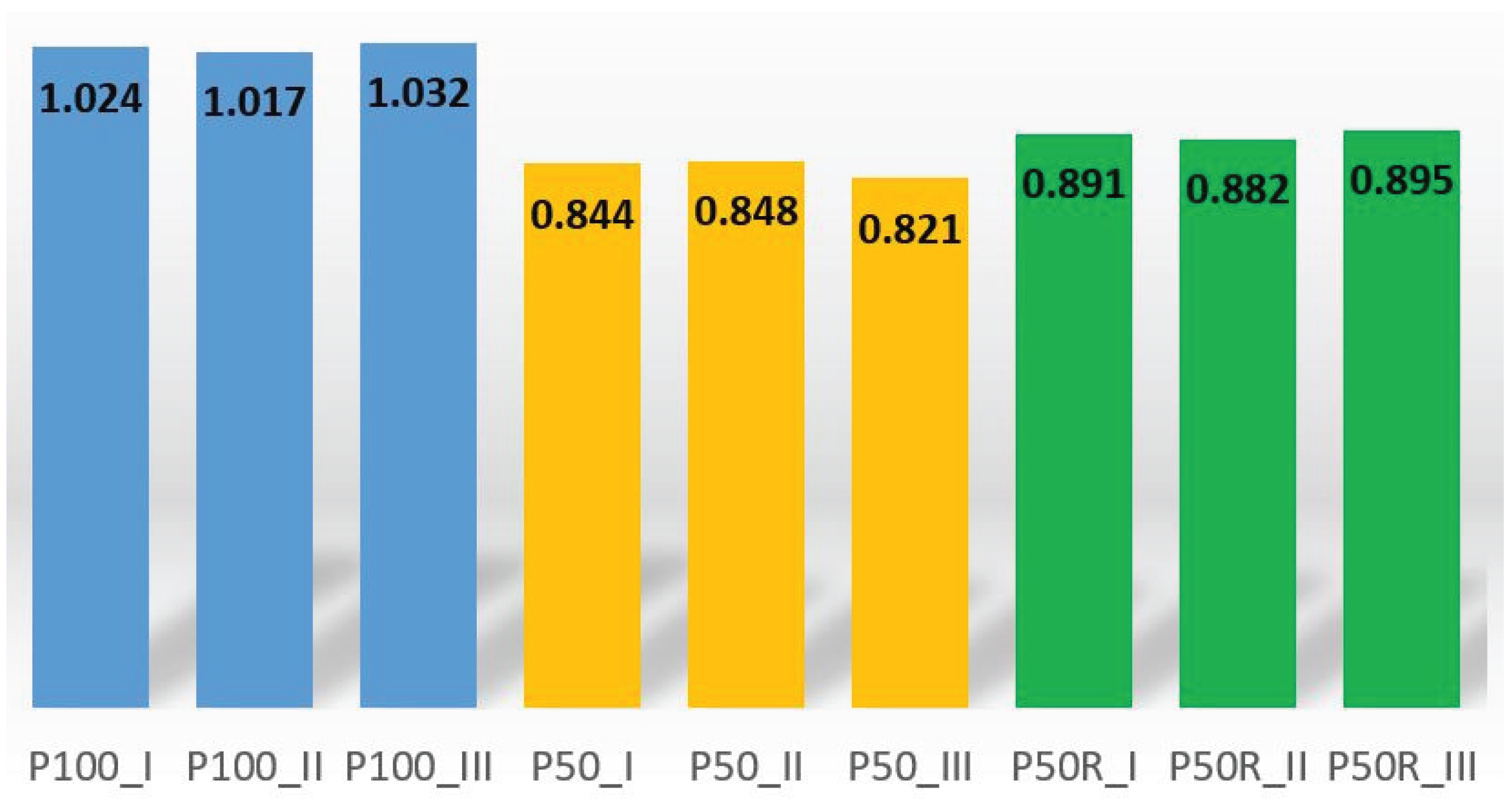
Figure 9.
Water absorbed per unit volume for the unreinforced specimens (P100, P50) and the sandwich specimens with 3D-printed core and CFF skin (P50R).
Figure 9.
Water absorbed per unit volume for the unreinforced specimens (P100, P50) and the sandwich specimens with 3D-printed core and CFF skin (P50R).
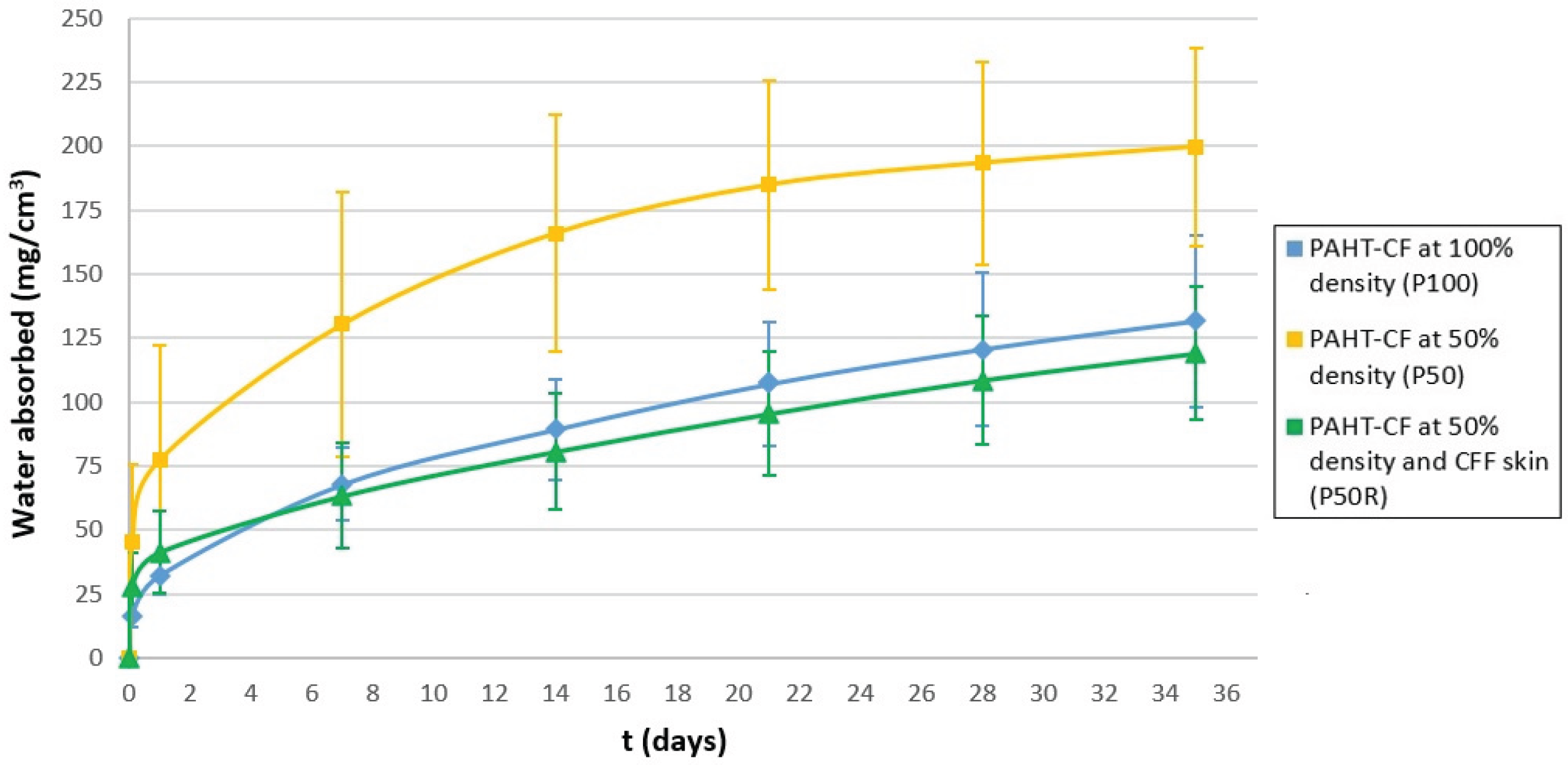
Figure 10.
Tensile stress - strain curves of the fabricated specimens.
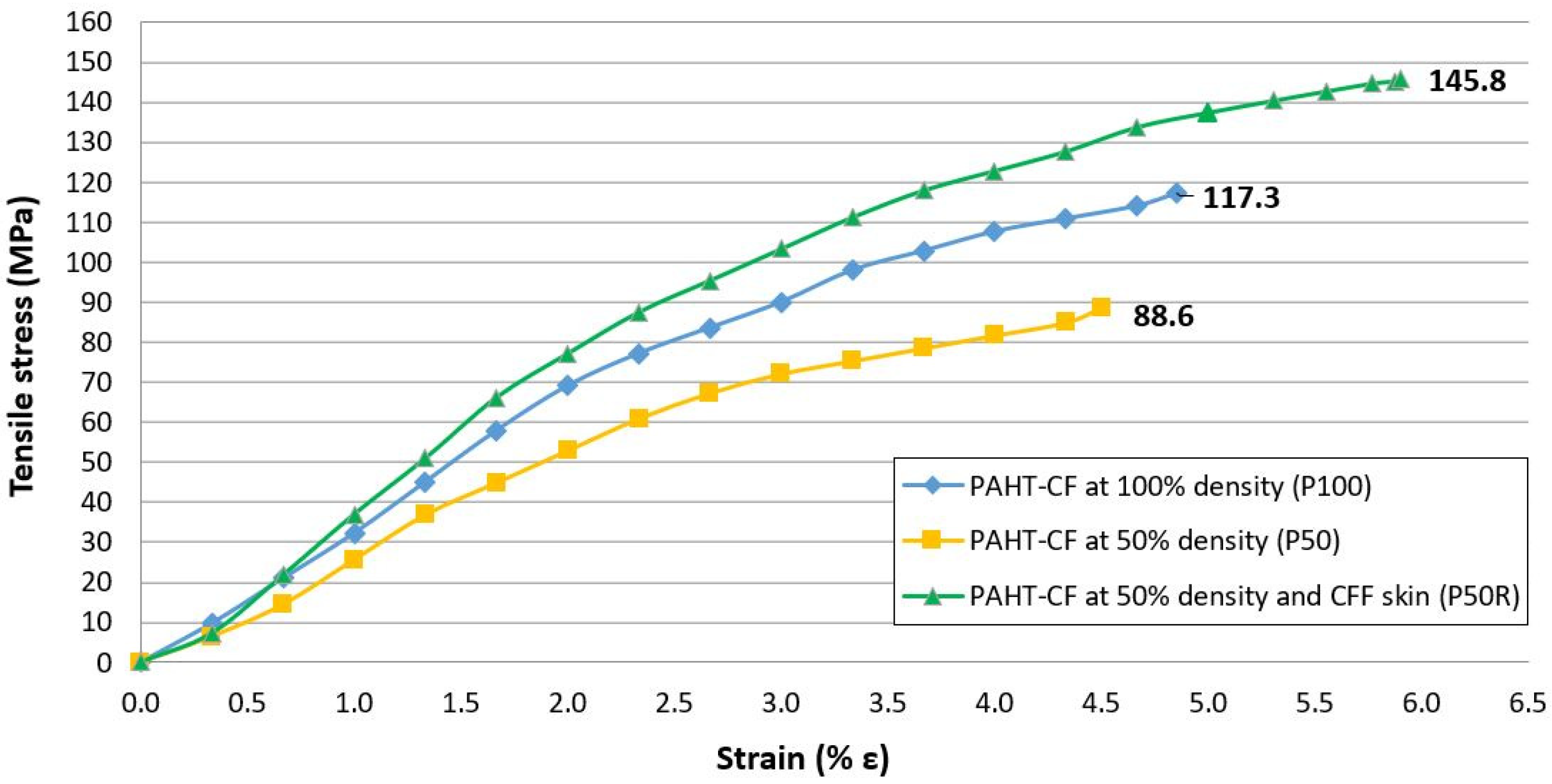
Figure 11.
Sandwich specimens (P50R) after fracture. The red line in the specimen no. 4 indicates the fracture line.
Figure 11.
Sandwich specimens (P50R) after fracture. The red line in the specimen no. 4 indicates the fracture line.
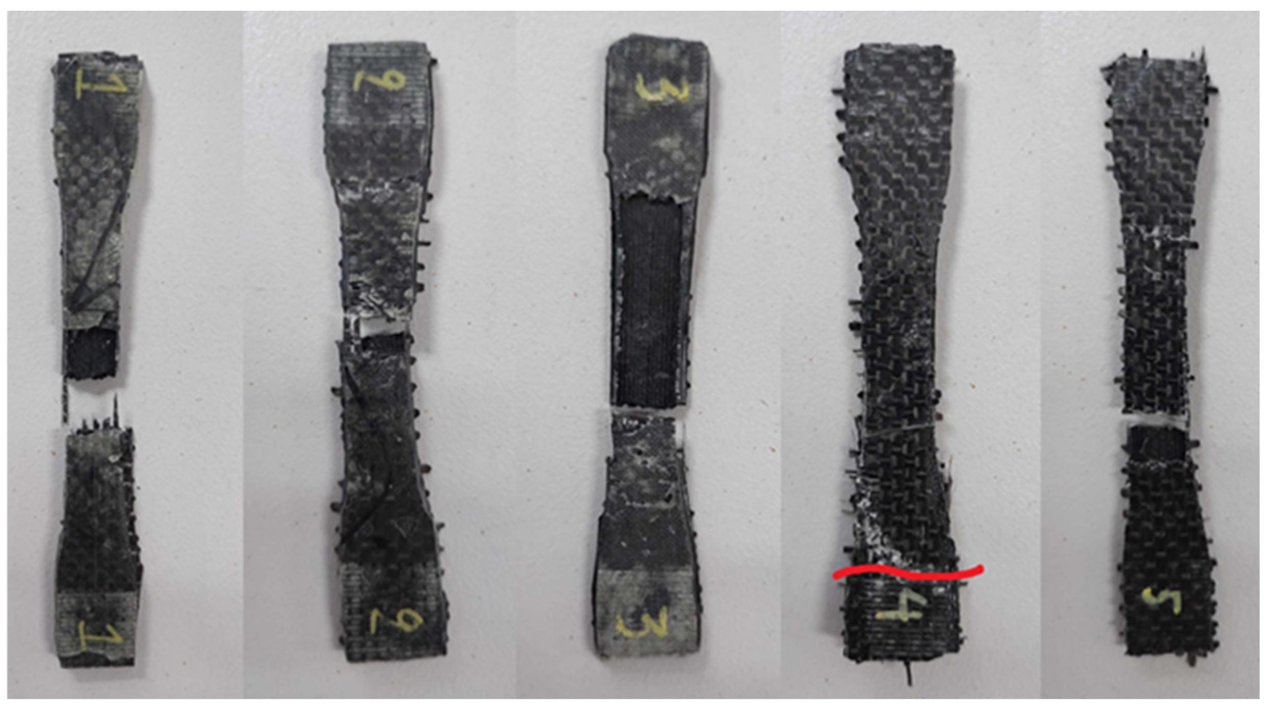
Figure 12.
Tensile stress - strain curves of the P50R sandwich specimens.
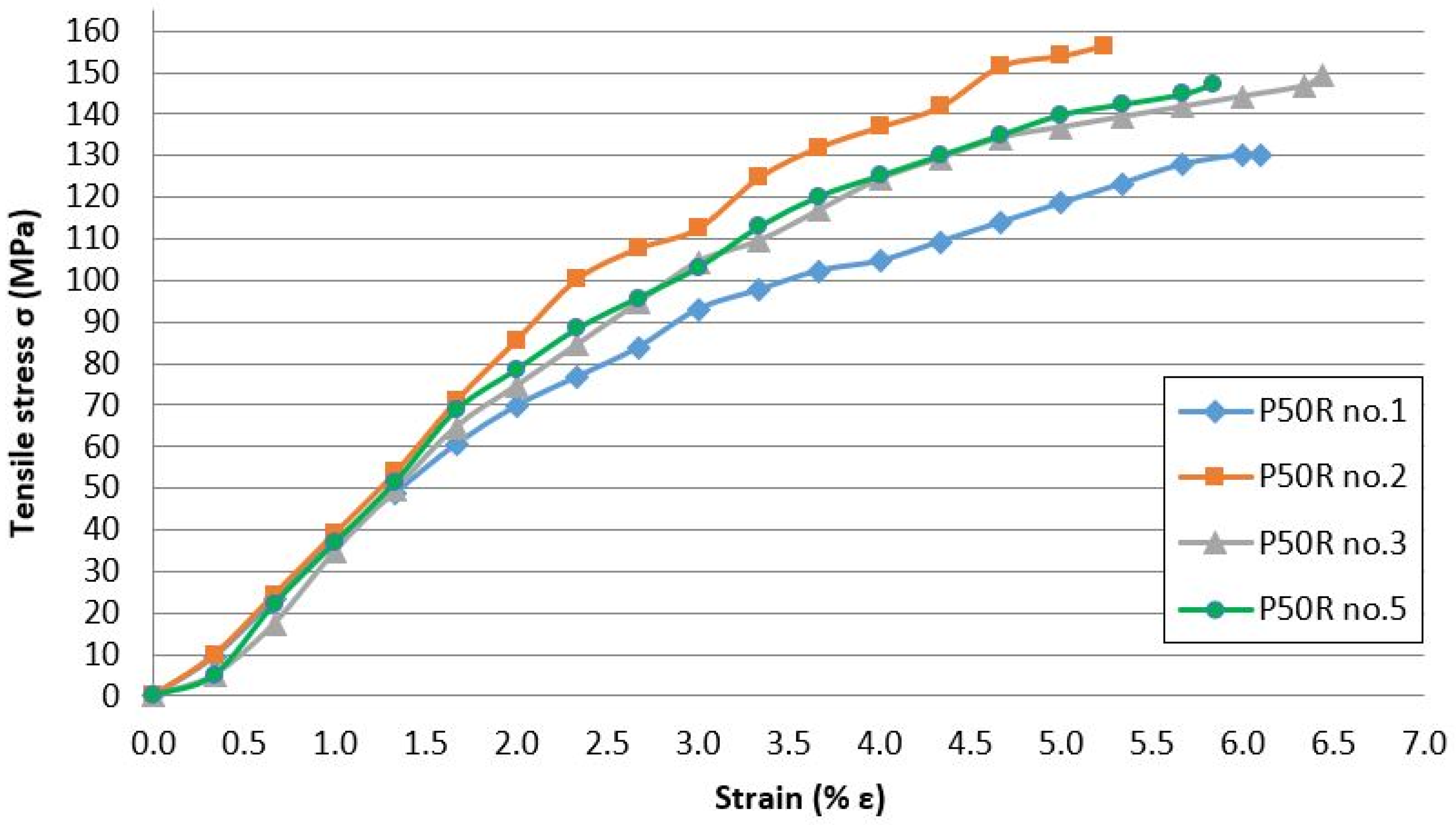
Figure 14.
Crack propagation of impact test specimens: (a,b) P50 specimen after face-up impact test; (c,d) P50R specimen completely fractured after side impact test; (e,f) P50R specimen with skin detachment after face-up impact test; (g,h) P50M specimens after face-up impact test.
Figure 14.
Crack propagation of impact test specimens: (a,b) P50 specimen after face-up impact test; (c,d) P50R specimen completely fractured after side impact test; (e,f) P50R specimen with skin detachment after face-up impact test; (g,h) P50M specimens after face-up impact test.
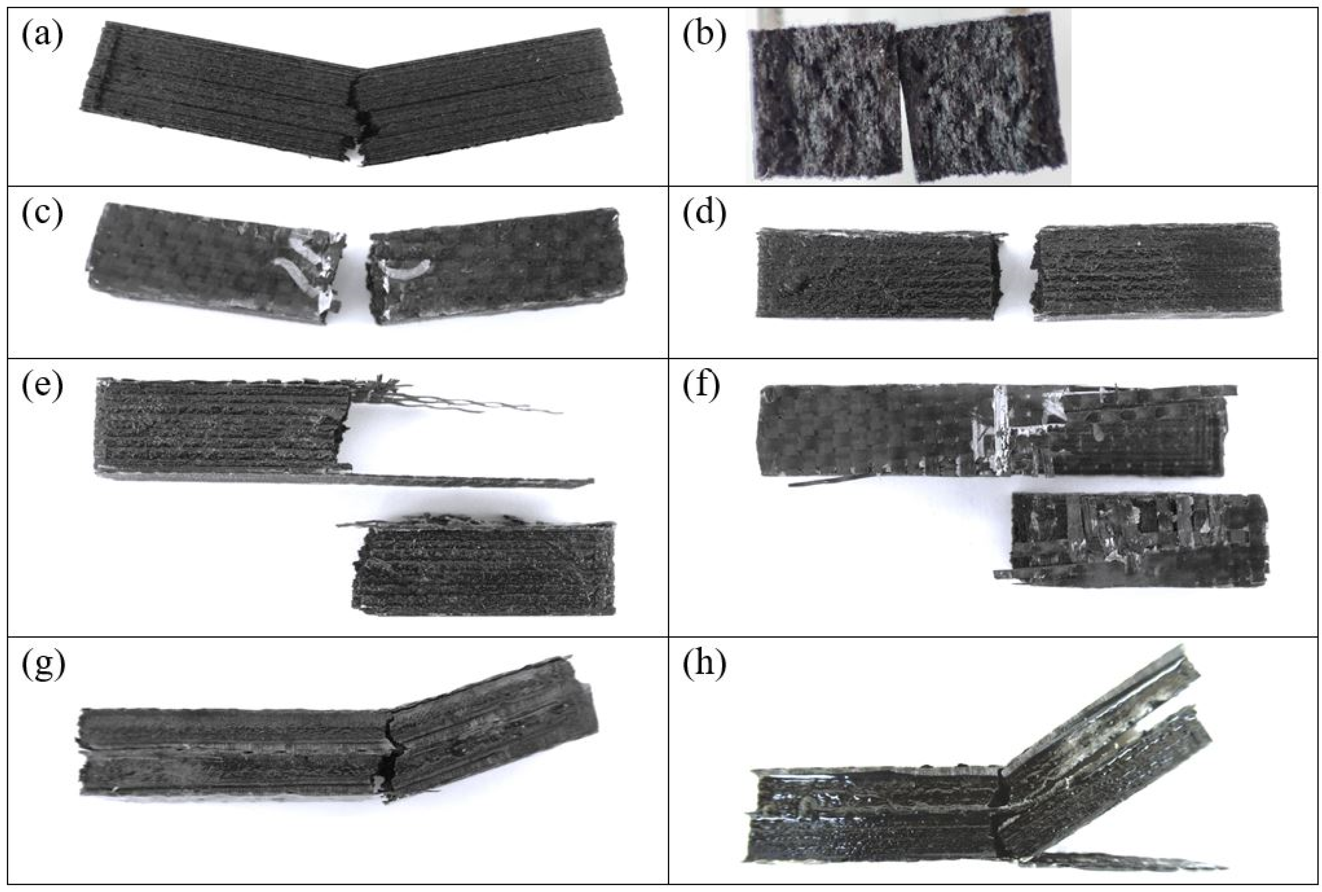
Figure 15.
Flexural strength of the fabricated specimens with respect to the bending force direction.
Figure 15.
Flexural strength of the fabricated specimens with respect to the bending force direction.
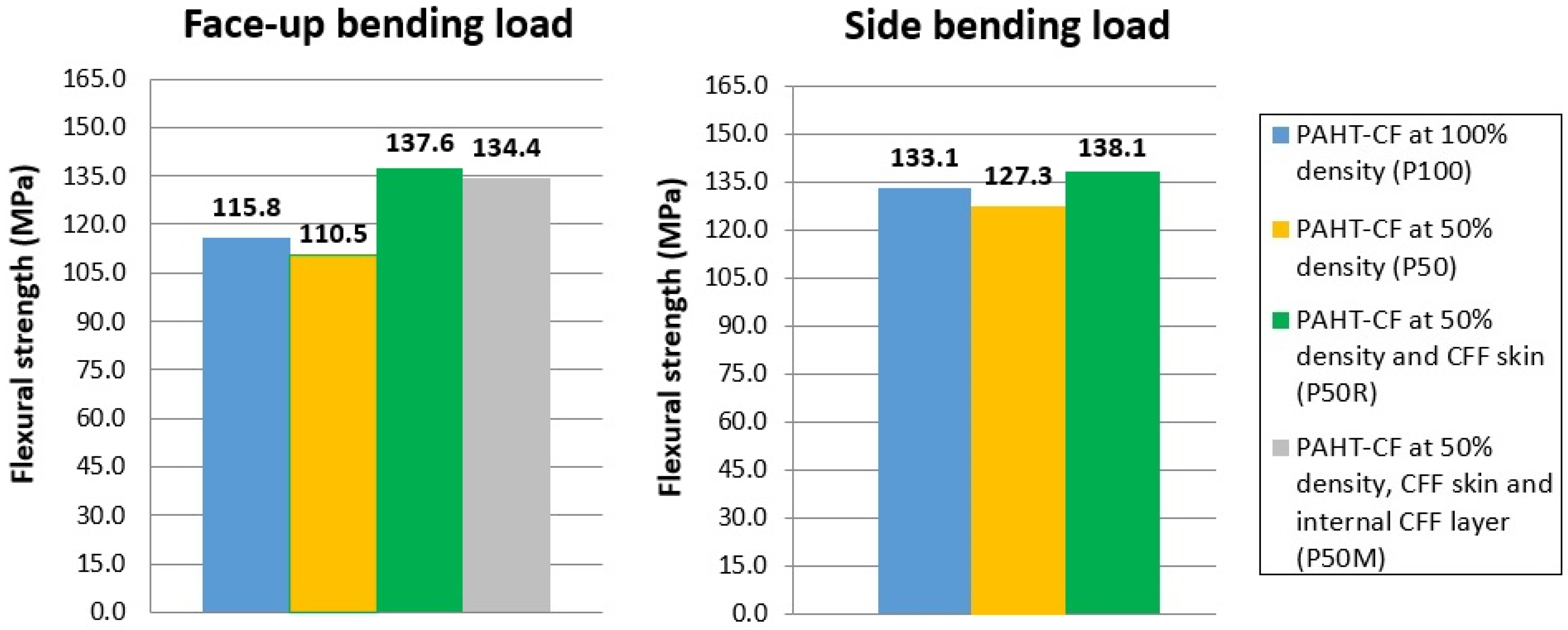
Figure 16.
Crack propagation of flexural test specimens: (a) P50 specimen after face-up bending test; (b) P50R specimens after side bending test; (c,d) P50R specimens after face-up bending test; (e,f) P50M specimens after face-up bending test.
Figure 16.
Crack propagation of flexural test specimens: (a) P50 specimen after face-up bending test; (b) P50R specimens after side bending test; (c,d) P50R specimens after face-up bending test; (e,f) P50M specimens after face-up bending test.
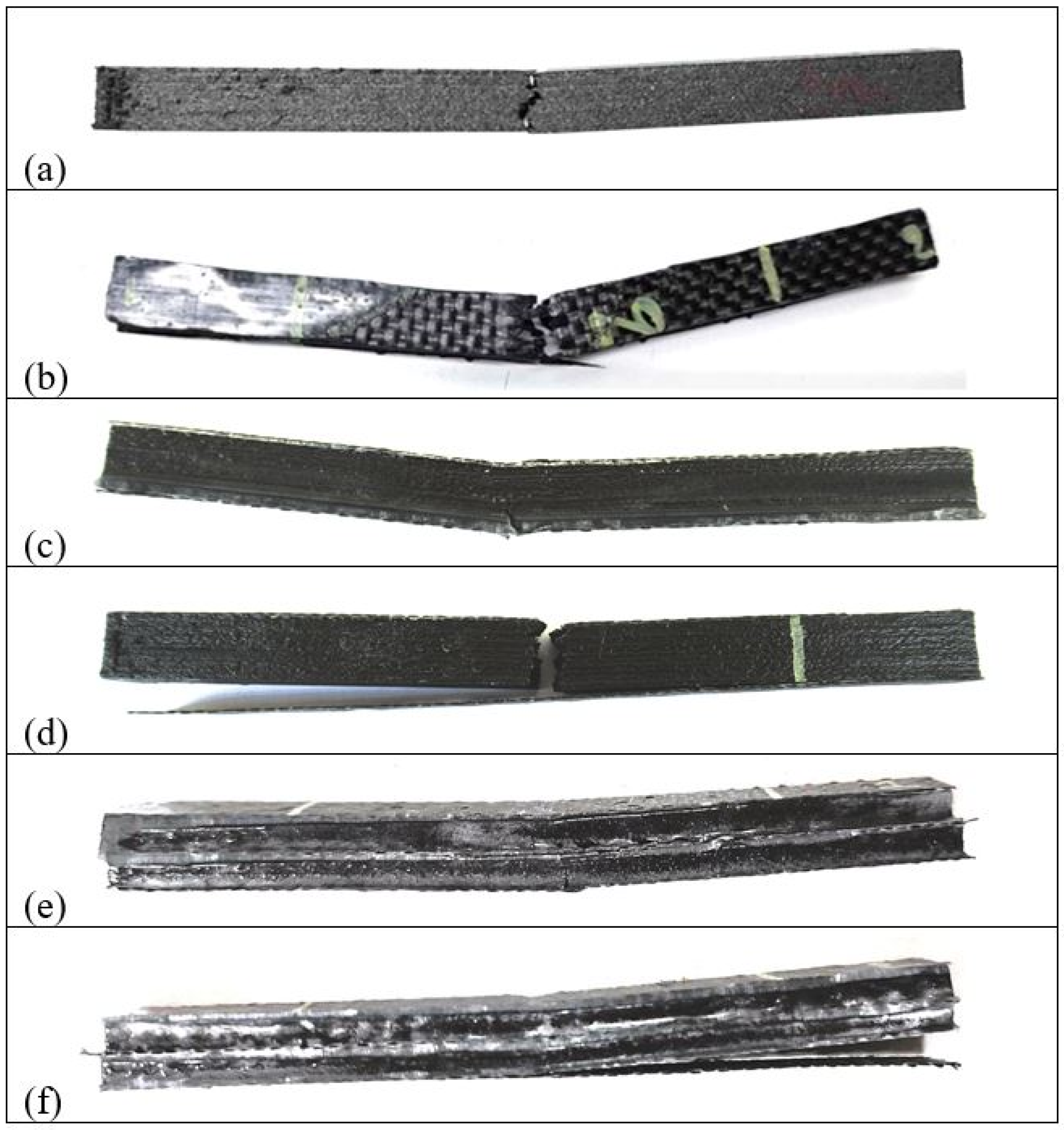
Figure 17.
(a) Side surface of P50R specimen (layer delamination during 3D printing is marked with red); (b) Side surface of P50M specimen with CFF skin and internal CFF layer.
Figure 17.
(a) Side surface of P50R specimen (layer delamination during 3D printing is marked with red); (b) Side surface of P50M specimen with CFF skin and internal CFF layer.
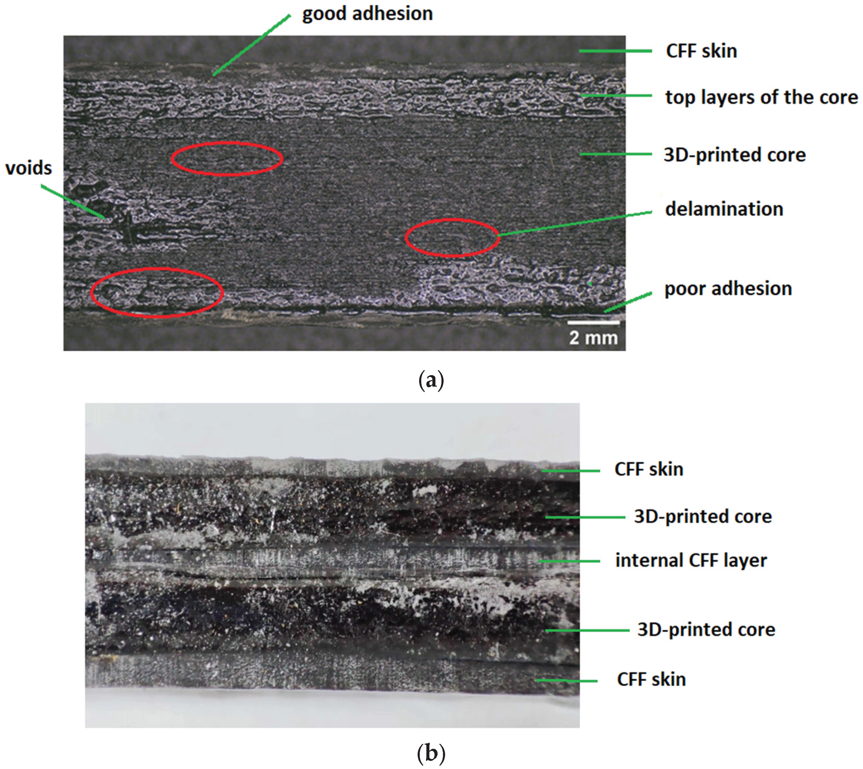

Table 1.
Recent experimental studies on sandwich structures with 3D-printed core and fiber-reinforced skin.
Table 1.
Recent experimental studies on sandwich structures with 3D-printed core and fiber-reinforced skin.
| Reference | Core Structure | Core Material | Skin Material | Tests |
|---|---|---|---|---|
| Alshaer 2021 [25] | honeycomb, re-entrant, pyramid, hierarchical pyramid and gyroid | PA12 | CFRP | three-point bending test |
| Ridlwan 2022 [26] |
honeycomb at 20% infill density | PLA, PC | GFRP for PLA, CFRP for PC |
bending rigidity |
| Zoumaki 2022 [27] |
honeycomb with three levels of hierarchy | PLA | fiberglass reinforced starch-based skin | three-point bending test |
| Acanfora 2023 [28] |
honeycomb with altering layers at 30% and 100% infill density | PP | CFRP | low-velocity impact test |
| Ainin 2023 [29] |
hexagonal honeycomb at 100% density varying unit cell sizes | PLA, PLA-CF, PLA-wood |
CFRP | low-velocity impact test |
| Forés - Garriga 2023 [30] | twelve 2D and seven 3D cellular cores | PEI Ultem® | CFRP |
three-point bending test |
| Junaedi 2024 [31] | gyroid at 10%, 15% and 20% infill density (PU foam into core cavities) | PLA | CFRP | flexural and compression tests |
| Francisco 2024 [32] | double arrowhead auxetic | PLA | carbon-aramid composite sheets | compression and vibration tests |
| Shah 2024 [33] | rectangular corrugated (PU foam into core cavities) | PA6-CF20%, PA6-GF25% | GFRP | quasi-static indentation test |
| Stepinac 2024 [34] | TPMS non-uniform gyroid | ASA | tempered glass | three-point bending test |
| Abas 2025 [35] | grid, cross3D and lightning at 20% density | PLA | GFRP | low-velocity impact test |
| Azeem 2025 [36] | Hexagonal, tri-hexagonal, triangles, at 10% and 100% density | PLA | GFRP | tensile properties |
| Brejcha 2025 [37] | truss-type structure | PLA, balsa, PVC foam | flax fiber fabric | three-point bending test |
| Kalaimagal 2025 [38] | triangular, hexagonal and trihexagonal at 40% infill density | PLA + GF16% | layers of aluminum and Kevlar fiber | low-velocity impact test |
| Mirzaei 2025 [39] | honeycomb | PLA | CFRP or GFRP | compression and bending test |
| Muralidharan 2025 [40] | honeycomb, x-shape, tubular hollow, triangular, tubular solid | PLA | CFRP | three-point bending test |
PA (polyamide), PLA (polylactic acid), PC (polycarbonate), PP (polypropylene), PEI (polyetherimide), ASA (acrylonitrile styrene acrylate), CF (carbon fiber), GF (glass fiber), PU (polyurethane), PVC (polyvinyl chloride), CFRP (carbon fiber reinforced polymer) or GFRP (glass fiber reinforced polymer); All studies refer to the hand lay-up technique apart from Ainin [29] and Fores-Garriga [30] (pressure vacuum bagging) and Brejcha [37] (vacuum infusion).
Table 2.
Recent experimental studies on 3D-printed carbon fiber-reinforced polymers with various infill patterns.
Table 2.
Recent experimental studies on 3D-printed carbon fiber-reinforced polymers with various infill patterns.
| Reference | Material | Infill Pattern | Printing Parameters | Properties | Outcomes |
|---|---|---|---|---|---|
| Naranjo- Lozada 2019 [44] | PA6, Onyx | rectangular, triangular | Variation of infill density (10%, 70%) | tensile strength at break, elastic modulus | The triangular pattern provided better tensile performance, as there were more strands oriented in the direction of load. |
| Rao 2019 [45] | PLA-CF |
cubic, cubic subdivision, quarter cubic | Variation of extrusion temperature and layer height (0.1mm, 0.2mm, 0.3mm) | tensile strength |
Tensile strength was mainly affected by layer height, followed by extrusion temperature and infill pattern. The highest tensile strength was obtained for the cubic pattern at 0.1 mm layer height and 225°C extrusion temperature. |
| Ma 2020 [46] | PLA, PLA-CF |
triangles, rectilinear, lines, honeycomb | 0.2 mm layer height; Variation of infill density (20%,40%, 60%, 80%) | compressive modulus, energy absorption capability | For PLA, the highest compressive modulus was obtained for the honeycomb pattern at 80% infill density, followed by triangle. For PLA/CF, the highest compressive modulus was obtained for the triangle pattern at 80% infill density, followed by honeycomb. |
| Mishra 2021 [19] | PLA-CF |
cubic, triangles, tri-hexagonal | Variation of layer height (0.1mm, 0.2mm, 0.3 mm), infill density (40%, 60%, 80%), printing speed | tensile and flexural strength |
The tri-hexagonal pattern provided higher tensile and flexural strength, followed by triangles and cubic. The highest tensile and flexural strength was obtained for the tri-hexagonal pattern at 0.3 mm layer height and 80% infill density. |
| Ansari 2022 [47] | PLA-CF |
grid, triangular, tri-hexagonal |
0.2 mm layer height; Variation of print speed, infill density (50%, 75%, 100%), nozzle temperature | impact Izod strength, hardness, dimensional accuracy | The maximum impact strength was obtained for the grid pattern at 75% infill density and 240oC nozzle temperature. The highest hardness value was obtained for tri-hexagonal pattern at 75% infill density and for the grid and triangular patterns at 100% infill density. |
| Pop 2022 [48] | PAHT-CF |
grid, lines, triangles |
0.2 mm layer height; 50% infill density | bending and tensile strength | Tensile strength was found higher for the lines pattern followed by triangles and grid. Bending strength was found higher for triangles followed by lines and grid. Defects decreased from grid pattern to lines pattern while they were insignificant for the triangles pattern. |
| Rodríguez-Reyna 2022 [20] | Nylon-CF, PLA, ABS |
tridimensional, hexagonal, linear | Variation of infill density (33%, 66%, 100%) | ultimate tensile stress, young’s modulus | For Nylon-CF, the higher tensile strength was obtained for tridimensional pattern, followed by hexagonal and linear, regardless of the infill density. |
| Sun 2023 [49] | PA6-CF20, PA6-CF25 | triangular, hexagonal, kagome, re-entrant |
0.15 mm layer height; 100% infill density; variation of raster angle | energy absorption capability | The kagome honeycomb pattern provided the highest specific energy absorption, with a value comparable to that of metals. |
| Abali 2024 [50] | PLA-CF | lines, gyroid | Variation of infill density (50%, 75%, 100%) | bending strength | Specimen with the lines pattern exhibited a higher maximum load compared to gyroid pattern at 75% and 100% infill densities, indicating higher toughness. |
| Andreozzi 2024 [51] | PA6, CF-GF |
concentric, grid, honeycomb | 0.25mm layer height, 50% infill density for honeycomb and grid, 100% infill density for concentric and grid | compression strength, modulus, yield, and strain at peak |
For 50% infill density, the grid pattern provided higher compression strength compared to honeycomb. For 100% infill density, the concentric pattern provided the highest compression strength and superior compression modulus. The highest peak deformation was observed for the grid pattern at 100% density. |
| Hozdić 2024 [52] | PETG, PETG-CF |
hexagonal, triangles, linear |
0.2 mm layer height; Variation of infill density (30%, 60%, 100%) | tensile strength young’s modulus, nominal strain at break | For both PETG and PETG-CF, the hexagonal pattern provided the highest tensile strength. The linear pattern provided the highest young's modulus indicating rigidity, but also lower ductility. |
Table 3.
Printing process parameters for PAHT-CF.
| Printing Parameters | Value |
|---|---|
| Layer height (mm) | 0.15 |
| Initial layer height (mm) | 0.27 |
| Raster width (mm) | 0.58 |
| Number of walls | 3 |
| Wall thickness (mm) | 1.74 |
| Number of top layers | 3 |
| Number of bottom layers | 3 |
| Top/bottom thickness (mm) | 0,9 |
| Build orientation | XY |
| Infill density (%) | 50%, 100% |
| Infill pattern | Lines, Cubic, Concentric |
| Top/bottom layers pattern | Lines, Concentric |
| Infill overlap | 10% |
| Infill flow, top/bottom flow | 100% |
| Print speed (mm/s) | 30 |
| Initial layer speed (mm/s) | 15 |
| Extrusion head type | CC 0.6 mm |
| Nozzle printing temperature (oC) | 270 |
| Build plate temperature (oC) | 100 |
| Raft material | None |
Table 4.
Different combinations of patterns for the infill and top/bottom layers.
| Infill Pattern | Top/Bottom Pattern | Code | |
|---|---|---|---|
| Lines | 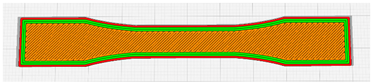 |
Lines | P100LL |
| Concentric |
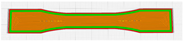 |
Concentric | P100OO |
| Cubic | 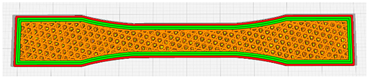 |
Lines | P100CL |
| Concentric | P100CO | ||
Table 5.
Tensile properties and impact strength for PAHT-CF specimens.
| Tensile Properties | Impact Strength (J/cm2) | |||
|---|---|---|---|---|
| Specimens | σmax (ΜPa) | % εmax | Face-Up | Side |
| P100LL | 93.4 ± 0.5 | 5.7 ± 0.3 | - | - |
| P100OO | 127.8 ± 3.4 | 7.0 ± 0.7 | 3.29 ± 0.08 | 2.63 ± 0.11 |
| P100CL | 96.5 ± 13.0 | 6.3 ± 1.0 | 2.65 ± 0.47 | 2.56 ± 0.09 |
| P100CO | 117.3 ± 4.5 | 4.8 ± 0.2 | 1.99 ± 0.16 | 2.51 ± 0.14 |
Table 6.
Dimensional measurements (in mm) of the 3D-printed PAHT-CF tensile specimens.
| Specimens | Length | Width | Thickness |
|---|---|---|---|
| P100LL | 100.39 | 10.41 | 3.17 |
| P100OO | 100.18 | 10.23 | 3.06 |
| P100CL | 100.71 | 10.48 | 3.14 |
| P100CO | 100.31 | 10.22 | 3.05 |
| CAD model | 100.00 | 10.00 | 3.00 |
Table 7.
Average values and standard deviation for water absorbed in a 35-days period.
| Specimens | Mass (g) | Water Absorbed (mg/cm3) |
St. Dev. | Water Absorbed (%) |
St. Dev. |
|---|---|---|---|---|---|
| P100 | 3.190 | 131.671 | 33.589 | 13.048 | 3.280 |
| P50 | 2.626 | 199.638 | 38.862 | 23.852 | 4.643 |
| P50R | 3.110 | 118.973 | 25.930 | 13.383 | 2.917 |
Table 8.
Shore D Hardness for the unreinforced specimens (P100) and the sandwich specimens with 3D-printed core and CFF skin (P50R).
Table 8.
Shore D Hardness for the unreinforced specimens (P100) and the sandwich specimens with 3D-printed core and CFF skin (P50R).
| Specimens | I | II | III | IV | V | Mean | |
| P100 | face-up | 79.5 | 78.5 | 79.0 | 78.0 | 80.5 | 79.1 |
| P100 | face-down | 80.5 | 81.5 | 79.5 | 76.0 | 80.0 | 79.5 |
| P100 | side | 72.5 | 71.3 | 70.0 | 70.5 | 70.5 | 71.0 |
| P50R | face-up | 82.5 | 86.5 | 82.3 | 86.5 | 80.5 | 83.7 |
| P50R | face- down | 82.5 | 81.5 | 84.5 | 80.0 | 82.8 | 82.3 |
Disclaimer/Publisher’s Note: The statements, opinions and data contained in all publications are solely those of the individual author(s) and contributor(s) and not of MDPI and/or the editor(s). MDPI and/or the editor(s) disclaim responsibility for any injury to people or property resulting from any ideas, methods, instructions or products referred to in the content. |
© 2025 by the authors. Licensee MDPI, Basel, Switzerland. This article is an open access article distributed under the terms and conditions of the Creative Commons Attribution (CC BY) license (http://creativecommons.org/licenses/by/4.0/).
Copyright: This open access article is published under a Creative Commons CC BY 4.0 license, which permit the free download, distribution, and reuse, provided that the author and preprint are cited in any reuse.


