Submitted:
13 July 2025
Posted:
15 July 2025
You are already at the latest version
Abstract
This work describes the design and testing of a hardware-in-the-loop (HiL) simulation system dedicated to automatic parking system (APA). The focus is on creating a laboratory environment that is as close to the real working conditions in order to provide realistic constraints. The proposed system comprises three key components: (1) an environment and vehicle kinematics simulation platform, (2) an integrated cockpit-parking computing platform executing both perception and path-planning algorithms, with the latter running on an isolated safety island, and (3) a microcontroller for vehicle chassis control. The system incorporates actual SoC hardware with peripheral circuits, along with deployed software and algorithm modules, enabling comprehensive system-level verification of the entire hardware-software pipeline. With enhanced observability features, our solution provides valuable references for early-stage APA system design and validation. Experimental results demonstrate that the proposed APA system meets mass-production requirements in both parking accuracy (achieving <5cm positioning error) and end-to-end latency (maintaining <100ms response time).
Keywords:
automatic parking assist
; hardware-in-the-loop
; APA
; HiL
; SoC
; CARLA
I. Introduction
Autonomous vehicles are becoming more and more widely used, but they need extensive tests and verification, Due to the requirements of the ISO 26262 a huge amount of test kilometer is required, presenting a significant challenge for automobile manufacturers and solution providers [1,2]. Since physical on-road testing is usually complicated and time consuming, sometimes even impossible. Simulation in laboratory setup is gaining great interest and popularity in these years.
The most common simulation methods are among Model-in-the-Loop (MiL), Software-in-the-Loop (SiL), and Hardware-in-the-Loop (HiL) [3]. MiL simulation or Model-Based Testing of a sub-system occurs at the very beginning of the project, the behaviors of this sub-system are abstracted into a model with MBD tools, such as MATLAB and Simulink. Once the sub-system model has been verified, the next stage is Software-in-the-Loop (SiL) where you replace the abstract model with generated codes (usually C/C++). In this stage, the validation of algorithm is to be focused on, without respect to timing constraints or bus systems. The third stage is Hardware-In-The-Loop (HiL) where the final hardware platform (Electronic Control Unit, ECU) is connected to the simulator, which mimics the behavior of a real car. Thus, the whole hardware together with the electrical interfaces and software is fully tested [4].
As a representative function of low-speed automatic driving, Automatic parking assist (APA) system could offer the convenience automatically park the vehicles in constrained environments where much attention and experience are required. It recognizes the parking space by sensing the surrounding environment information of the vehicle through ultrasonic or image sensors, and according to the relative position information of the vehicle and the parking space, generate the corresponding parking trajectory and control the speed of the vehicle and the steering wheel to complete the automatic parking. Since the first automobile equipped with APA system in 2003, the research and development in this technology spread from automobile enterprises to vehicle research centers of institutions and universities over twenty years [5]. And in recent years the most popular solution of APA has rapidly transitioned from ultrasonic-based to vision-based.
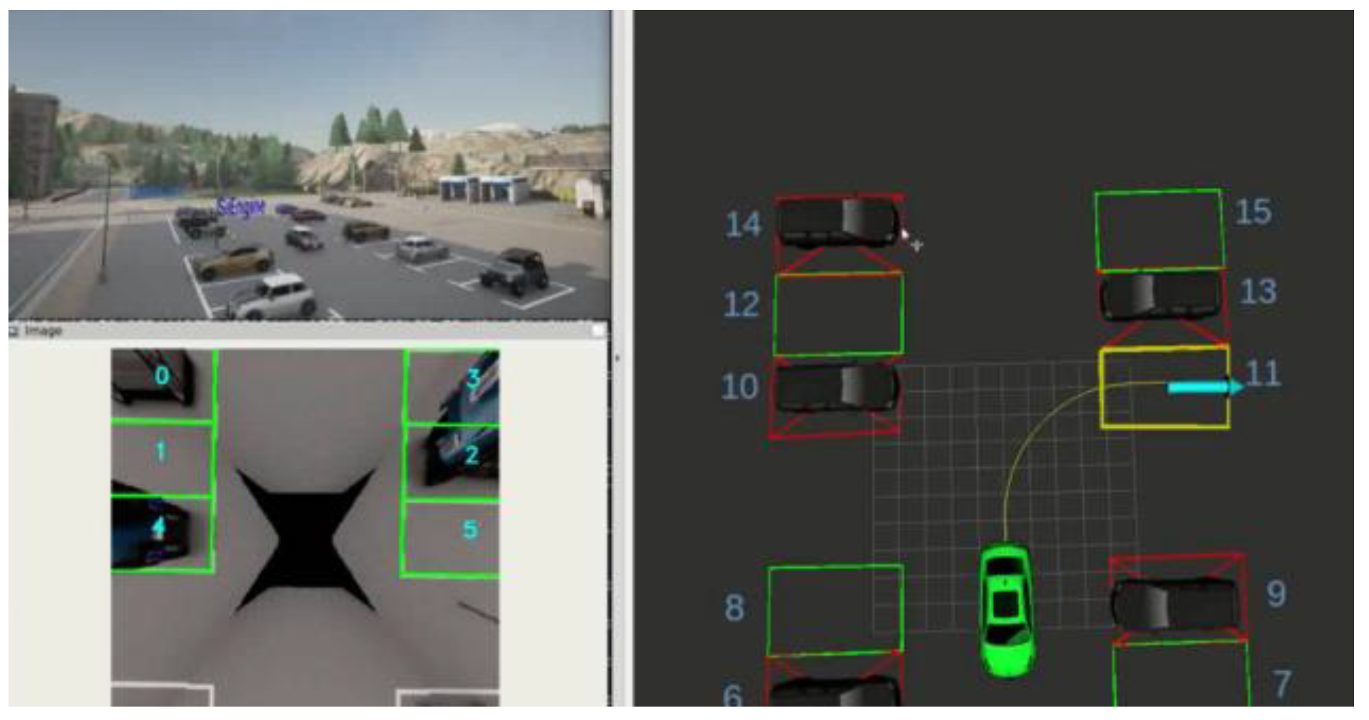
Figure 1.
Holistic view of the simulation, with CARLA on the top-left, parking slot detection (PSD) on the bottom-left, and planning and control (PnC) on the right.
Figure 1.
Holistic view of the simulation, with CARLA on the top-left, parking slot detection (PSD) on the bottom-left, and planning and control (PnC) on the right.
To evaluate and analyze the performance of the APA system, several methods have been proposed [6,7]. However, due to its prerequisites for environment and sensor configuration , full pipeline testing of vision-based APA system with ECU in the loop is still not fulfilled in laboratory.
We therefore developed a closed-loop, end-to-end HiL simulation system for comprehensive laboratory validation of APA functionality. This system enables full verification of all the hardware and software modules in the pipeline, including video processing, neural network acceleration, communication interfaces, safety island, etc. Moreover, it facilitates precise latency measurement for each functional module, significantly enhancing system observability.
A. Related Work
Parking-slot detection is the critical process for vision-based APA, there is an increasing number of publicly available software projects in the field of parking-slot detection. Among these approaches, [8,9] are mainly traditional methods, marking-lines first or marking-points first, for each pair of marking-lines or marking-points, different methods are used to determine whether it forms a parking slot. [10,11,12,13] are mainly deep learning methods, tends to have better accuracy performance. DMPR-PS [10] is a two-stage method. In the first stage, a novel CNN-based model is used to regress the orientation, coordinate, and shape of marking points, and in the second stage, the manually designed geometric rules are applied to filter and match paired marking points.
Most of these PSD methods are validated on dataset ps2.0 [14], which was established for the study of vision-based parking-slot detection. ps2.0 is the largest and the most comprehensive one of its kind. It contains 12,165 surround-view images collected from typical indoor and outdoor parking sites. However, ps2.0 only provides stitched BEV images instead of surrounding view images, which are critical in HiL simulation pipeline.
Planning and control are also key components for APA system [15,16,17]. Path planning generation algorithm determines a suitable collision-free path from a given start to a required goal position within the parking space, which is the core issue of APA system. Path planning is merely an open-loop method, it should cooperate with tracking controller to make actual APA system work out so that forming a state feedback closed-loop control.
As for HiL simulation for autonomous driving, several methods have been proposed in recent years, but methods dedicated for APA system is rarely seen. [18] developed a laboratory environment to support the design, test and verification of many functions and algorithms related to active safety, driver-assist and sensor-guided autonomous driving features, such as adaptive cruise control, collision preparation and avoidance control, lane change, etc. In [19] a combination of a lane keeping system, and a cooperative cruise control system is simulated in this preliminary study in their HiL simulator Level 2 autonomous vehicle model. [20] developed an integration between CARLA and ROS, verified the correlation between real and simulated sensor measurements, established and verified that neither simulation nor real vehicle require hard real-time constraints to operate, and quantified the time saved through use of simulation experiments as an initial step before experiments on real vehicles.
B. Contribution
In this approach, we present a closed-loop HiL simulation scheme for automatic parking assist. The entire pipeline is divided into three sections: the first section is a x86 server running CARLA simulator, which gives out necessary sensor data and updates vehicle kinematic model with feedback control command, the second section is a SE1000 SOC running most of the algorithm modules including localization, perception and planning, the third section is a RH850 MCU specifically for control algorithms.
We also present a latency measurement method for APA system simulation, end-to-end latency between data generation and control feedback is measured, furthermore latency between every two function modules can be calculated after time synchronization.
The remaining of this paper is structured as follows. Section II provides a detailed description of the simulation pipeline, especially the hardware and software architecture. Section III explains the algorithm modules in the closed loop pipeline. Results obtained from the experiments are presented in Section IV. Section V derives conclusions from the work, and we further discuss the future research directions.
II. System Architecture
We outline our hardware requirements in Sec. II-A. Following that, we provide an overview of the framework in Sec. II-B. Subsequently, we detail the map, vehicle and sensor configuration of CARLA in Sec. II-C. Finally, Sec. II-D and II-E present a detailed description of SE1000 and RH850 platform.
A. Hardware Requirements
The hardware devices of this work shown in Figure 2 is presented in this section. The HiL setup consists of two main parts: the first part is a X86 Server with one Video Injection Card in PCIE slot, and two CAN channel extended by USBCAN, the second part is an evaluation board includes SoC, MCU and necessary interfaces for automotive applications. The specifications of these parts are listed in Table 1.
The SoC connects with x86 server via various interfaces. The GMSL interface between Injection Card and MAX96722 transmits YUV422 video data of Quad 1920x1080 cameras, which is then forwarded to MIPI CSI Rx on the SoC. At the same time odometry packets are transmitted over serial bus, the debug info and structured data generated by SoC are published to x86 visualization tool over ethernet.
The PnC data between SoC and MCU are exchanged via SPI bus, finally the CAN messages containing control commands are fed back to x86 server with the help of a USBCAN device.
B. Overview of Pipeline
The pipeline is a closed loop as shown in Figure 3. Data flow starts from sensors in the CARLA simulator, the surround view cameras output four synchronized images, together with the odometry, flow into Sensor Service on SoC, and distribute further to other software modules via SEFlow, the middleware provided with SE1000 SDK.
Localization subscribes the odometry and transform it into world coordinate frame.
Perception consists of four sub-modules, the first sub-module stitches four surround view images into a BEV image, this operation is accelerated by GPU, the second sub-module detect parking slots on the BEV image, the third sub-module detect objects in the surround view images and locates them in world coordinate, and the fourth sub-module builds a parking map with available slots and objects.
The parking map is published to Safety domain and acts as the basis for path planning. The other input of planning is the specified slot position comes from HMI module, and the generated trajectory is passed to control module.
MCU calculates throttle and brake for longitudinal control and steer rate for lateral, these commands value together with timestamp are serialized into three standard CAN frames and sent to x86 server every cycle.
The CAN frames are parsed and converted to CARLA VehicleControl structure, which is feedback to kinematic model in the CARLA server. If controller works properly and latency is within appropriate range, the vehicle will perform successful parkin following the planned path.
C. CARLA Configuration
CARLA is an open-source autonomous driving simulator [21]. It was built from scratch to serve as a modular and flexible API to address a range of tasks involved in the problem of autonomous driving. One of the main goals of CARLA is to help democratize autonomous driving R&D, serving as a tool that can be easily accessed and customized by users. We use CARLA 0.9.13 for our simulation.
In CARLA a map includes both the 3D model of a town and its road definition. Town04 is a small map embedded in the mountains with a square parking area. To better test our algorithms, we made some modifications to this parking area as shown in Figure 4, two columns of half-closed perpendicular parking lots are arranged facing each other, all the slots are set to 5 meters length and 3.2 meters width, half of the parking lots are occupied by vehicles leaving the others empty.
There are dozens of cars, trucks and other vehicles in the CARLA catalogue, we choose vehicle.mini.cooper_s for our HiL simulation, the key parameters of this vehicle are listed in Table 2.
Four surround view cameras and one odometry are attached to ego vehicle, the detailed configuration is listed in Table 3.
There is a ros-bridge provided with CARLA designed to transfer sensors data from CARLA client to ROS middleware [22,23], but only supporting UDP is the limitation. So we leverage the PCIE video injection card to achieve better HiL simulation, the images produced by CARLA client are converted to YUV422 format, attach both CARLA and host machine timestamps, and push into PCIE sending queue. Afterwards, trigger signal from deserializer MAX96722 will scrape the four image channels simultaneously. Independently, the odometry data are transmitted via UART bus in the format of a GNSS sensor, also with both CARLA and host machine timestamps for synchronization.
D. SE1000 CDP Platform
The SE1000 CDP Platform provides a solution that supports high-end Cockpits and low-level ADAS (L2&APA) on a single chip. According to SDK Specification, there are three hardware domains in SE1000 SOC:
- IVI domain based on 4xA76 + 2xA55.
- ADAS domain based on 2xA55.
- Safety domain based on 1xR52 (dual lockstep).
There are four software domains. The AP0 hardware domain is divided into two software domains through the Linux container mechanism: Android (LXC-0) and Cluster (LXC-1):
- LXC-Android domain (In AP0): It focuses on infotainment usage based on Android including games, navigation map, video/audio player and recorder, OMS, DMS etc.
- LXC-Cluster domain (In AP0): It focuses on digital cluster usage, including dashboard, HUD etc.
- Driving and Parking domain (In AP1): It focuses on L2&APA usage including Perception & Localization.
- Safety domain (In R52): It focuses on safety related application like safety display for TT icon, planning algorithm for APA&L2.
The IVI domain, which is split into LXC-Android and LXC-Cluster, is more for cockpit applications, the APA pipeline runs mainly on ADAS and Safety domain.
On ADAS domain, algorithm modules are built upon middleware SEFlow. SEFlow is a distributed data distribution and task scheduling framework, which combines the flexibility of ROS2 with the safety and dynamic deployment capabilities of Adaptive AUTOSAR. It is compatible with ROS2’s vast developer community and rich open-source tools while adopting Adaptive AUTOSAR’s Service-Oriented Architecture (SOA) design. SEFlow supports multiple transport-layer protocols, such as DDS, SOME/IP, and ZMQ in a plugin manner, enabling seamless adaptation to various automotive software architectures. SEFlow enables the easy transfer of large volumes of data to multiple receivers using DMABUF zero-copy technology. It supports various QoS settings during transmission and allows thread and coroutine-level scheduling through XML configuration files. SEFlow offers various transmission methods, supporting inter-process communication, different hardware isolation domains within the same SoC, or chip-to-chip transmission via PCIE. Its diverse transmission options are well-suited for autonomous driving applications.
Safety domain uses FreeRTOS[24] as the real-time operating system. FreeRTOS has the advantages of a good development ecosystem, complete development documentation, a large number of development users, low learning costs, and easy deployment. Considering the functional safety requirements of the on-board controller, functional safety-related components and non-functional safety-related components are required to not interfere with each other.
There is a micro version of SEFlow on safety domain FreeRTOS platform, providing dataflow and schedule of multiple tasks.
E. RH850 RTOS Platform
The MCU RH850 by Renesas is tailored for a wide range of automotive control systems. Specifically, in this work, RH850 is responsible for the power management of the entire EVB, gateway control, and chassis interfaces including CAN and automotive Ethernet, among others. Additionally, the superior functional safety characteristics (ISO 26262 ASIL-D compliant) of RH850 enabled reliable deployment of our chassis control algorithms.
Like SE1000 Safety domain, FreeRTOS and micro SEFlow are also ported to RH850 platform, controller logics are built upon micro SEFlow APIs.
F. Time Synchronization
In this scheme, MCU RH850, usually connects to GNSS sensor, servers as Time Master, while the other parts as Time Slaves, synchronize with MCU using gPTP. as shown in Figure 5.
Usually x86 server uses NTP (Network Time Protocol) to synchronize with UTC time, leads to tens of milliseconds error through the internet. However, after synchronizing with MCU via LAN, the x86 server host timestamp achieves microsecond-level accuracy.
Besides host timestamp, CARLA provides a sensor timestamp, which starts counting from the very beginning of simulation, with microsecond precision. This sensor timestamp can be used to match frames between multiple sensors. We packet these timestamps together with sensor data and pass along with data flow. As for image frames, the timestamps are inserted into the first 16 bytes overwriting 8 pixels, as shown in Figure 6.
Host timestamp is passed along all the intermediate messages in SEFlow, and feedback to x86 server in CAN frames. A software module on x86 server retrieves the host timestamp in CAN frames and calculates end-to-end latency by comparing it with current host time.
G. Human-Machine Interface
RVIZ2 is used as human-machine interface in two aspects, the first is visualization of intermediate results including BEV image, PSD boxes and ego vehicle trajectory etc. and we added a plugin to RVIZ2 for richer visual effects. The second is issue commands to the vehicle, specifically the goal parking slot location, leveraging the “2D Goal Pose” tool of RVIZ2. Path Planner subscribes the command and make a trajectory planning in topic callback.
III. Algorithms
In the APA pipeline, several algorithms are employed, some of them are offloaded to hardware accelerators, sections III-A to III-F detail the implementation of some key modules.
A. Surround View Stitching
The parking-slot detection algorithm is applied on the BEV (bird-eye view) image. On our experimental car, four surround view cameras are mounted. From these camera inputs, a composite BEV image around the vehicle can be synthesized.
Automotive surround view cameras, also called around view cameras or surround vision monitoring system, is an emerging automotive ADAS technology that provides the driver a 360° surrounding of the vehicle. Such systems normally consist of four to six fish-eye cameras mounted around the vehicle, for example, one at the front bumper, another at the rear bumper, and one under each side mirror [25].
The Carla simulator supports only pinhole camera projection model which can be applicable for narrow-view camera modelling and wide-view with FOV (field of view) up to 120 degrees, so we attach 4 FOV 120° cameras to the experimental vehicle. Based on the intrinsic and extrinsic of each camera, a homography matrix is calculated, and each pixel in the surround view image is mapped to BEV perspective according to the homography. An example of surround view stitching is given by Figure 7.
The stitching function is implemented in one OpenCL kernel, and deployed on GPU1 of SE1000, operation speed increased more than ten times compared to CPU. The Mali GPU driver supports OpenCL version 1.2, which specifies an API for parallel programming that is designed for portability.
B. Parking Slot Detection
one of the key issues of APA pipeline to be addressed is how to correctly detect and locate parking-slots with in-vehicle sensors. Solutions to this problem fall into two categories, USS-based ones and camera-based ones, more and more impressive camera-based approaches are proposed these years, making it a more universal and robust solution.
A camera-based approach detects parking slot markings to locate parking slots. Parking slot markings are the line-shaped markings painted on the ground to indicate a valid parking space. We chose the DMPR-PS method [10] for our simulation. After stitching, a BEV image of 512x512 resolution is passed to the PSD module, and directional marking points in the image are located with DMPR, a CNN model. After detecting the marking points and applying non maximum suppression, parking-slots could be inferred from the points, according to [10].
We deployed the DMPR model on NPU1 of SE1000, the model inference reaches 30Hz in unit testing. Figure 7 shows the PSD results, all the inferred slots are marked with green boxes.
C. Object Detection
Unlike PSD method, object detection operates directly on surround view images. A YOLO-based method is used to detect vehicles in the surround view images, and the bounding boxes are projected to world coordinate, after matching with PSD results, an attribute is attached to each slot, indicates whether it is occupied by another vehicle, and a parking map is built with this information. The bounding boxes of nearby vehicles are also taken into account by the path planning method.
D. Localization
Localization is relatively easy with the help of CARLA client APIs. For each Actor in CARLA, a getter named get_transform is provided to retrieve its location and rotation, another getter named get_velocity for its linear velocity and angular velocity. These parameters are packed into an odometry frame and transmit to Sensor Service on SE1000 via serial bus.
Localization module subscribes the odometry topic, transform it into world coordinate frame, and further distributes to Fusion Mapping and PnC modules.
E. Path Planner
As it is usual in the literature, the vehicle can be described by the kinematic model of the bicycle [26]. Both the path planning and tracking control algorithms use this model.
An implementation of line-arc planner is employed. The origin of the ego vehicle coordinate locates at center of the rear axles, trajectory of ego vehicle consists of straight lines and arcs, as shown in Figure 8. At first, a path is generated with default curvature, if path has intersection with nearby objects, another path with smaller or larger curvature is calculated in search of a collision-free path.
F. Tracking Controller
The path tracking problems of autonomous vehicles have been studied abundantly these years. For APA controller module, the most concerning issue is how to park the vehicle at a specified location and attitude.
To track the line-arc path, controller outputs both lateral and longitudinal commands. Steer is set to zero in line segments and calculated based on arc curvature. Velocity setpoint is limited to 1.5 m/s, throttle and brake value are calculated with a PI controller, according to velocity error between setpoint and current velocity from Localization.
IV. Results
We conducted the HiL simulation illustrated in Section II, analyzed multiple performance metrics for APA algorithms, and measured pipeline latency to give an insight into the simulation.
A. Performance Benchmark
In the Town04 park as Figure 4 shows, we made 30 parking tests, the average results can be seen in Table 4.
In these overall tests, all the parking slots are detected successfully, all the commands are executed correctly, the displacement and orientation precision perform well, and parking time is acceptable.
B. Pipeline Latency
Following steps in Section II.F we made detailed analysis of the pipeline latency. In particular, the end-to-end latency, which starts from sensor data transmission and ends to CAN command feedback, is 83 milliseconds. If only the algorithms on SE1000 and RH850, the latency is 53 milliseconds. More detailed information shows in Figure 9.
V. Conclusion
We have presented an HIL automatic parking simulation system that is capable of feedback closed-loop control commands. We have detailed the architecture of the software framework utilized on the SoC and MCU processors, and how this framework was able to simplify the development of the APA system due to its high flexibility. We have shown that this system allows for software to be tested in an environment that presents similar performance constraints as the real-world parking lots, and further research shows detailed analysis can be obtained more conveniently in HiL simulation than real-world.
This closed-loop HiL simulation system we developed provides a system-level testing methodology for SoC that more closely resembles real-world application scenarios. This approach significantly enhances system observability and serves as a valuable complement to unit testing, enabling more comprehensive verification of both hardware and software during the development phase.
In the future we will continue devoting our efforts to a more efficient and robust algorithm solution. Additionally, future efforts should include a CARLA extension supporting fisheye lens camera, to facilitate more practical surround view stitching.
References
- P. Koopman and M. Wagner, “Challenges in Autonomous Vehicle Testing and Validation” SAE International Journal of Transportation Safety, vol. 4, no. 1, pp. 15–24, Apr. 2016.
- P. Koopman and M. Wagner, “Toward a Framework for Highly Automated Vehicle Safety Validation”, in WCX World Congress Experience, Apr. 2018, pp. 2018–01–1071.
- Dapynhunlang Shylla, Ayushi Jain, Pritesh Shah, and Ravi Sekhar, “Model in Loop (MIL), Software in Loop (SIL) and Hardware in Loop (HIL) Testing in MBD”, 2023 4th IEEE Global Conference for Advancement in Technology (GCAT). [CrossRef]
- Gregor Sievers, Caius Seiger, Michael Peperhowe, Holger Krumm, and Sebastian Graf, “Driving Simulation Technologies for Sensor Simulation in SIL and HIL Environments”, DCS 2018.
- Yuyu Song and Chenglin Liao, “Analysis and Review of State-of-the-Art Automatic Parking Assist System”, 2016 IEEE International Conference on Vehicular Electronics and Safety (ICVES). [CrossRef]
- Zhuo Kaimin, Chen Tao, Jiang Zhuofan, Zhang Yue, and Wang Xu, “Automatic Parking System Performance Testing Based on Indoor Positioning System”, 2023 IEEE International Conference on Image Processing and Computer Applications (ICIPCA).
- ZHANG Jia-xu, GUO Chong, WANG Chen, ZHAO Jian, and WANG Xin-zhi, “Performance evaluation of automatic parking system based on hardware in the loop simulation platform”, July 2022, Journal of Jilin University (Engineering and Technology Edition).
- Marco Allodi, Luca Castangia, Alessandro Cionini, and Francesco Valenti, “Monocular parking slots and obstacles detection and tracking”, 2016 IEEE Intelligent Vehicles Symposium (IV). [CrossRef]
- Linshen Li, Lin Zhang1, Xiyuan Li, Xiao Liu, Ying Shen, and Lu Xiong, “VISION-BASED PARKING-SLOT DETECTION: A BENCHMARK AND A LEARNING-BASED APPROACH”, 2017 IEEE International Conference on Multimedia and Expo (ICME).
- Junhao Huang, Lin Zhang, Ying Shen1, Huijuan Zhang, Shengjie Zhao, and Yukai Yang, “DMPR-PS: A NOVEL APPROACH FOR PARKING-SLOT DETECTION USING DIRECTIONAL MARKING-POINT REGRESSION”, 2019 IEEE International Conference on Multimedia and Expo (ICME).
- Chen Min, Jiaolong Xu, Liang Xiao, Dawei Zhao, Yiming Nie, and Bin Dai, “Attentional Graph Neural Network for Parking-slot Detection”, IEEE Robotics and Automation Letters ( Volume: 6, Issue: 2, April 2021).
- HOSEOK DO and JIN YOUNG CHO, “Context-Based Parking Slot Detection With a Realistic Dataset”, IEEE Access(Volume: 8).
- Zhuoping Yu, Zhong Gao, Hansheng Chen, and Yuyao Huang, “SPFCN: Select and Prune the Fully Convolutional Networks for Real-time Parking Slot Detection”, 2020 IEEE Intelligent Vehicles Symposium (IV). [CrossRef]
- L. Zhang, J. Huang, X. Li, and L. Xiong, “Vision-based parking-slot detection: A DCNN-based approach and a large scale benchmark dataset”, IEEE Trans. IP, vol. 27, no. 11, pp. 5350–5364, 2018.
- Kunpeng Cheng,Ye Zhang, and Hui Chen, “Planning and Control for a Fully-automatic Parallel Parking Assist System in Narrow Parking Spaces”, 2013 IEEE Intelligent Vehicles Symposium (IV). [CrossRef]
- Xiaolin Tang, Yuyou Yang, Teng Liu, Xianke Lin, Kai Yang, and Shen Li, “Path Planning and Tracking Control for Parking via Soft Actor-Critic Under Non-Ideal Scenarios”, IEEE/CAA Journal of Automatica Sinica ( Volume: 11, Issue: 1, January 2024). [CrossRef]
- Soumyo Das, Meer Reshma Sheerin, Sabarish R. P. Nair, Prashantkumar B. Vora, Rastri Dey, and Milankumar A. Sheta, “Path Tracking and Control for Parallel Parking”, 2020 International Conference on Image Processing and Robotics (ICIP).
- Weiwen Deng, Yong H. Lee, and Annie Zhao, “Hardware-in-the-loop Simulation for Autonomous Driving”, 2008 34th Annual Conference of IEEE Industrial Electronics.
- Şükrü Yaren Gelbal, and Mustafa Rıdvan Cantaş, Santhosh Tamilarasan, Levent Güvenç, Bilin Aksun-Güvenç, “A Connected and Autonomous Vehicle Hardware-in-the-Loop Simulator for Developing Automated Driving Algorithms”, 2017 IEEE International Conference on Systems, Man, and Cybernetics (SMC).
- Craig Brogle, Chao Zhang, Kai Li Lim, and Thomas Bräunl, “Hardware-in-the-Loop Autonomous Driving Simulation Without Real-Time Constraints”, IEEE Transactions on Intelligent Vehicles (Volume: 4, Issue: 3, September 2019).
- A. Dosovitskiy, G. Ros, F. Codevilla, A. M. Lopez, V. Koltun, “CARLA: an open urban driving simulator,” CoRR, vol.abs/1711.03938, 2017.
- “CARLA-ROS-Bridge” [Online]. Available: https://github.com/carla-simulator/ros-bridge.
- Gemb Kaljavesi, Tobias Kerbl, Tobias Betz, Kirill Mitkovskii and Frank Diermeyer, “CARLA-Autoware-Bridge: Facilitating Autonomous Driving Research with a Unified Framework for Simulation and Module Development” Feb 2024, arXiv:2402.11239v1 [cs.RO].
- “FreeRTOS” [Online]. Available: https://www.freertos.org/.
- Buyue Zhang, Vikram Appia, Ibrahim Pekkucuksen, Aziz Umit Batur, Pavan Shastry, Stanley Liu, and Yucheng Liu, “A surround view camera solution for embedded systems”, 2014 IEEE Conference on Computer Vision and Pattern Recognition Workshops.
- Emese Sz’adeczky-Kardoss and B’alint Kiss, “Path Planning and Tracking Control for an Automatic Parking Assist System”, European Robotics Symposium 2008 (pp.175-184).
Figure 2.
System topology and data flow diagram.
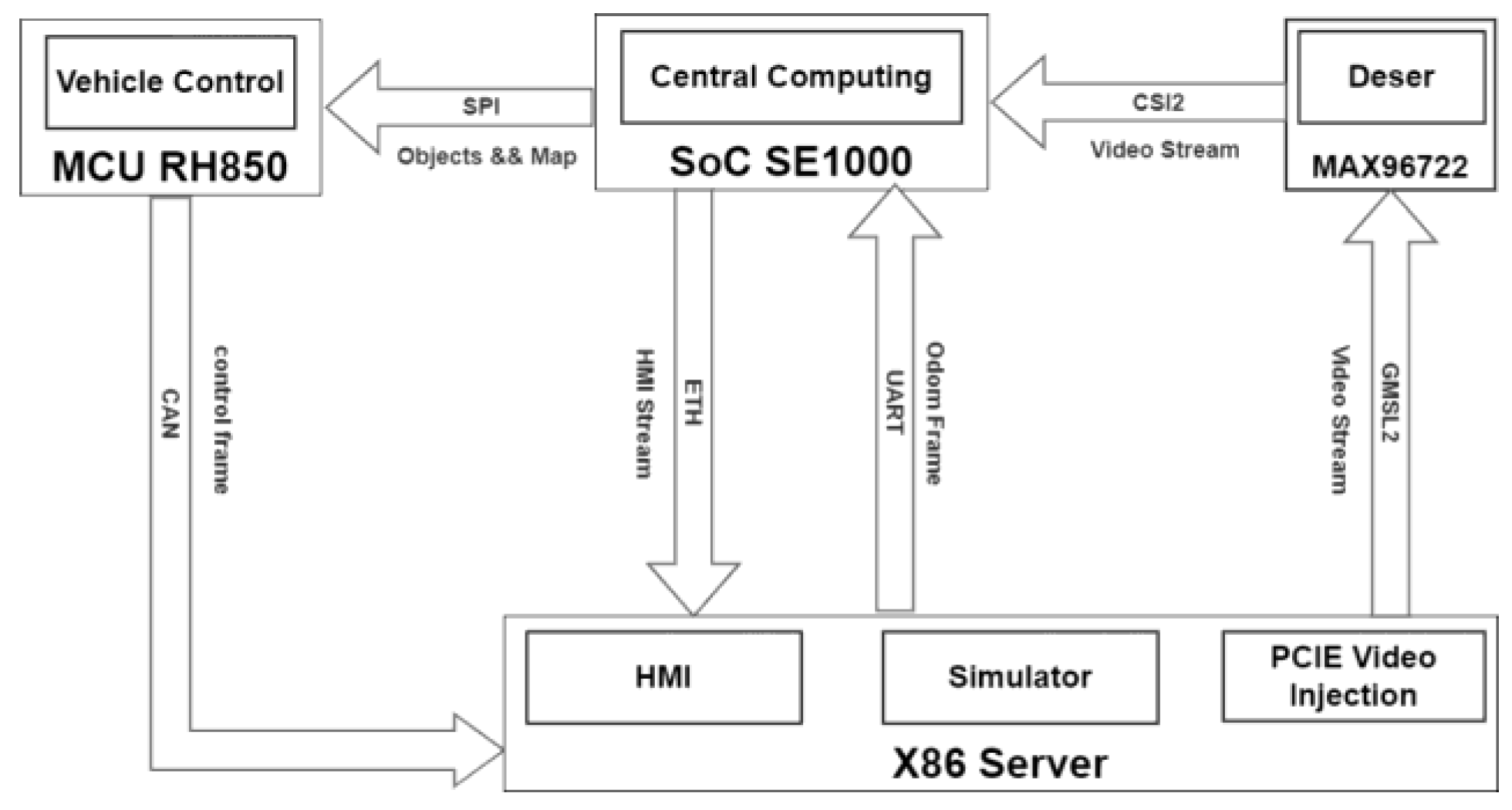
Figure 3.
Block diagram illustrating the closed loop pipeline of the proposed HiL simulation. The pipeline starts with surround view images and odometry generated by CARLA on x86 server, in the perception procedure, it builds a parking map with available slots and objects. Based on this map and ego vehicle pose given by localization procedure, trajectory to the dedicated parking slot can be generated by path planner. MCU can track the path by feedback commands to the vehicle kinematic model.
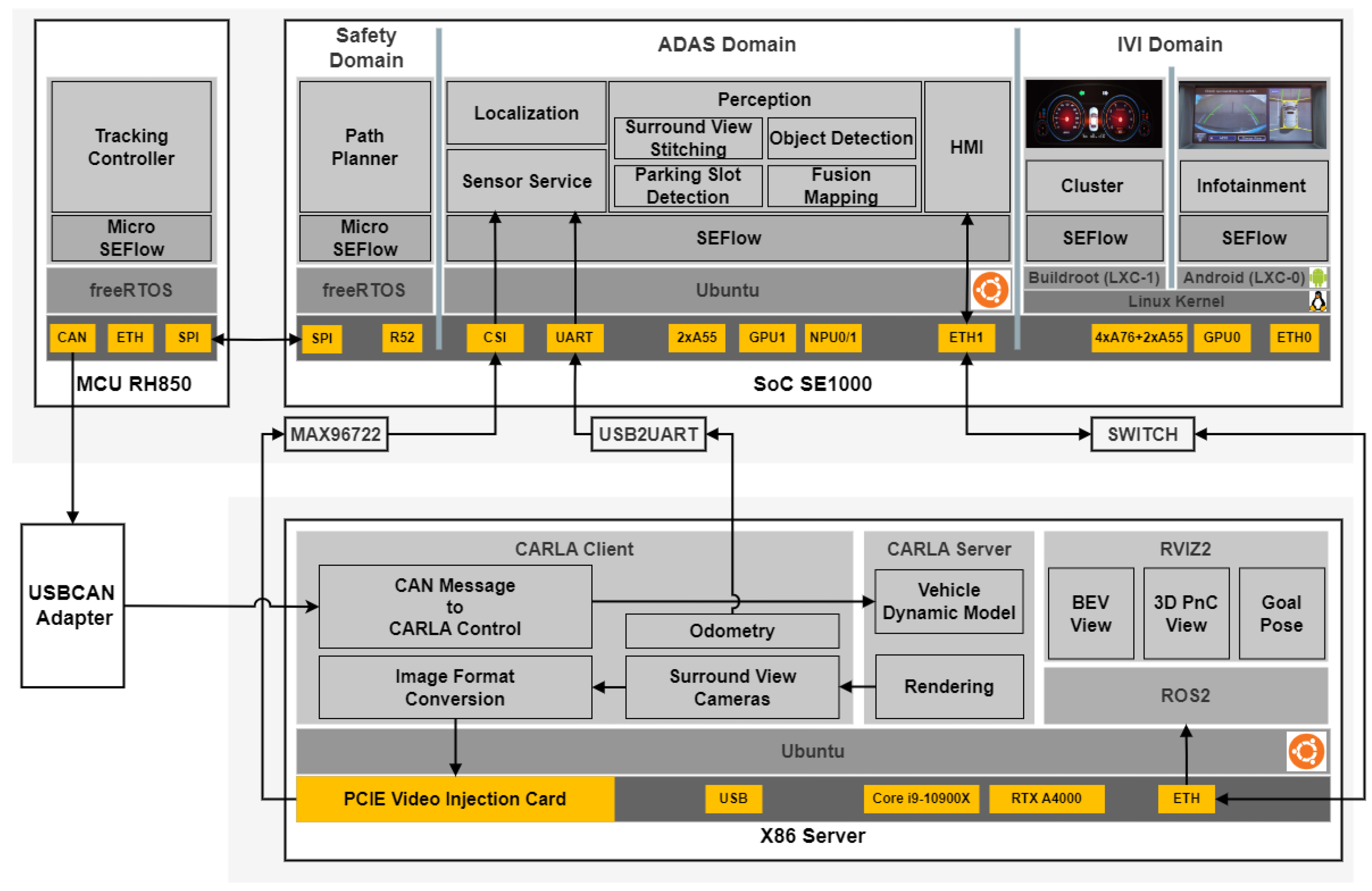
Figure 4.
Parking lots in CARLA Town04.
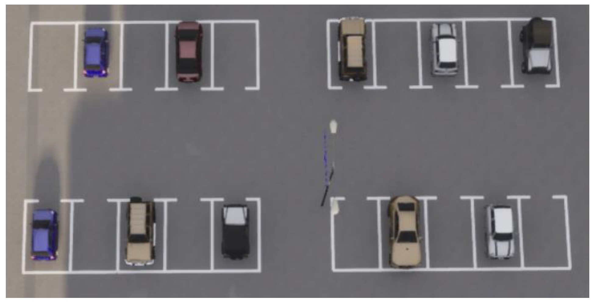
Figure 5.
Diagram of time synchronization across all the devices.
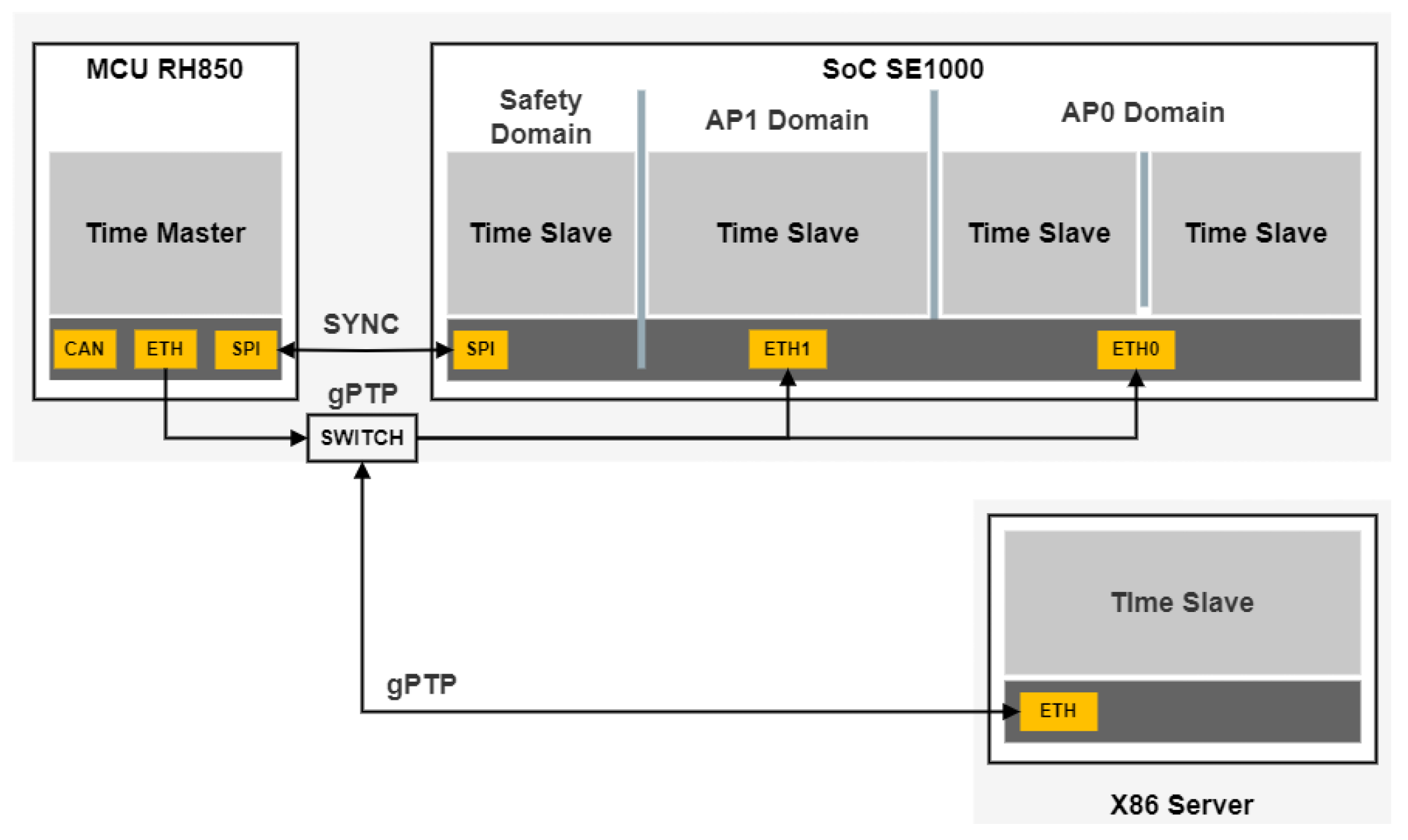
Figure 6.
Timestamp passed along the pipeline for synchronization and latency calculation.
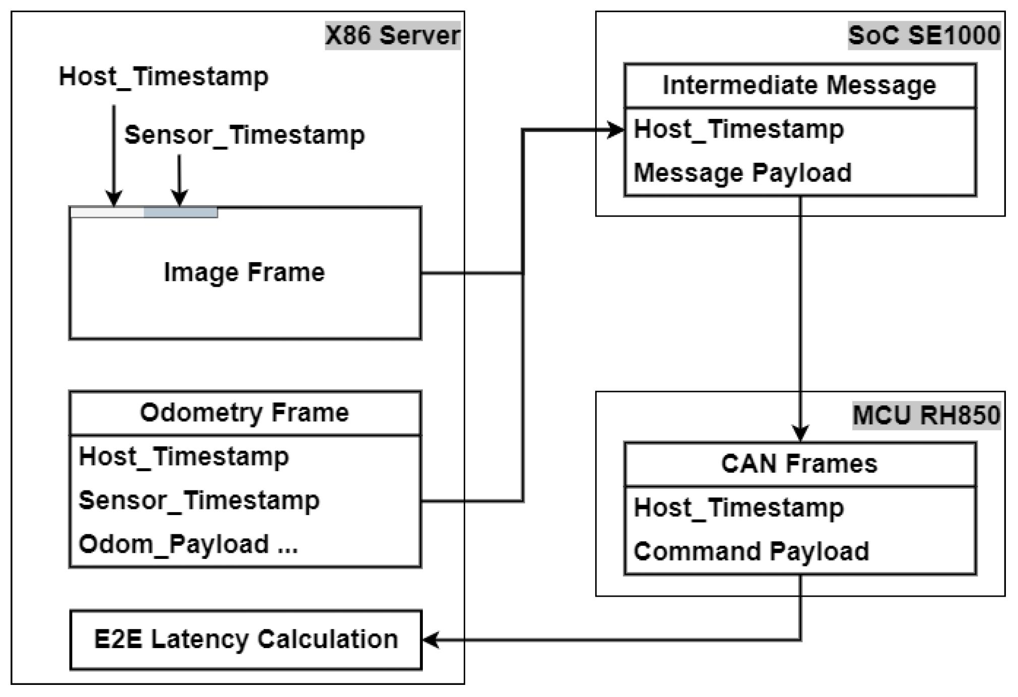
Figure 7.
Surround view images and stitched BEV image with PSD results (direction of the cameras indicated by the car-sticker).
Figure 7.
Surround view images and stitched BEV image with PSD results (direction of the cameras indicated by the car-sticker).
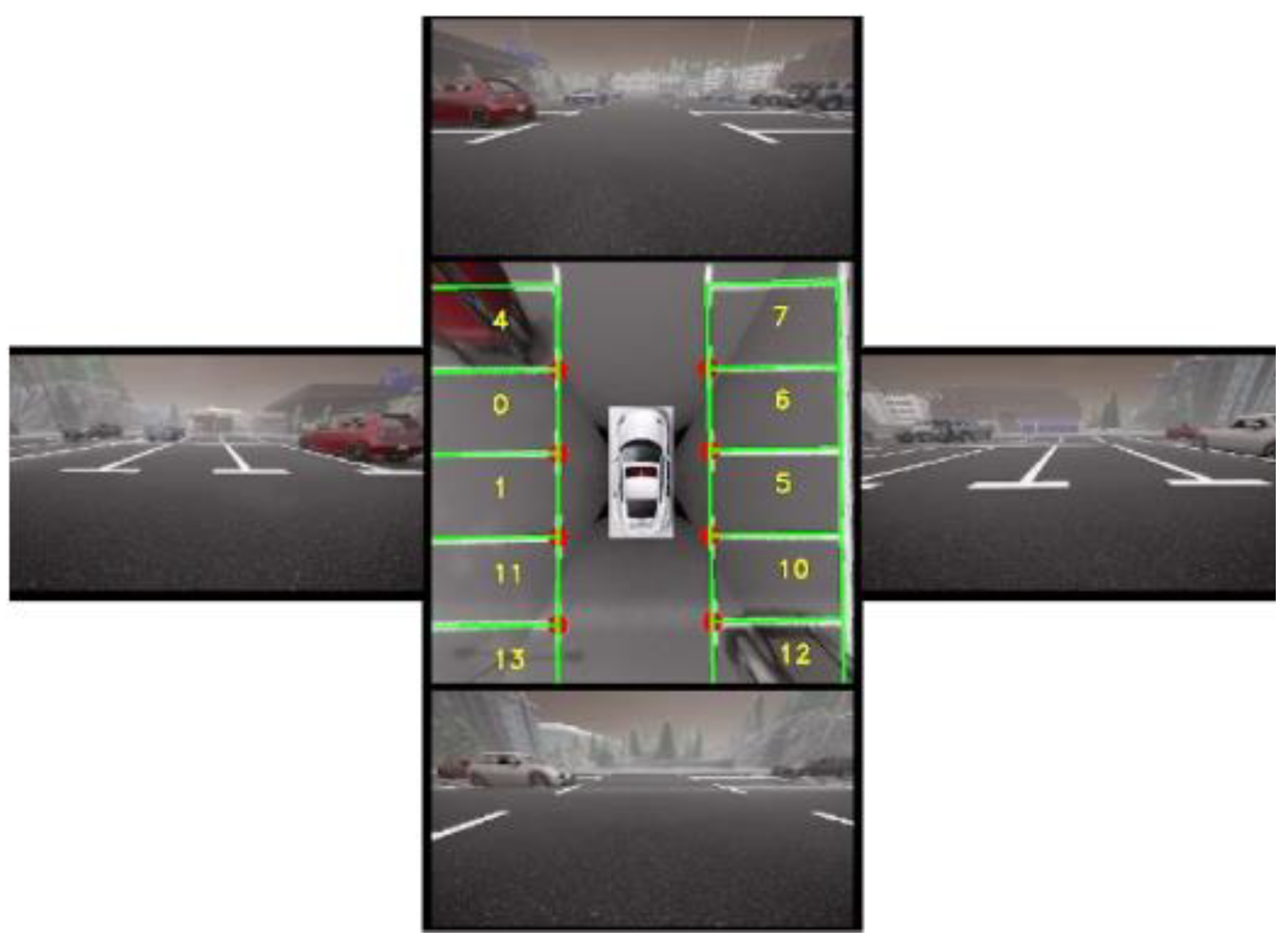
Figure 8.
Diagram of the line-arc planning method. The example path contains three segments: line S1, arc S2, and line S3.
Figure 8.
Diagram of the line-arc planning method. The example path contains three segments: line S1, arc S2, and line S3.
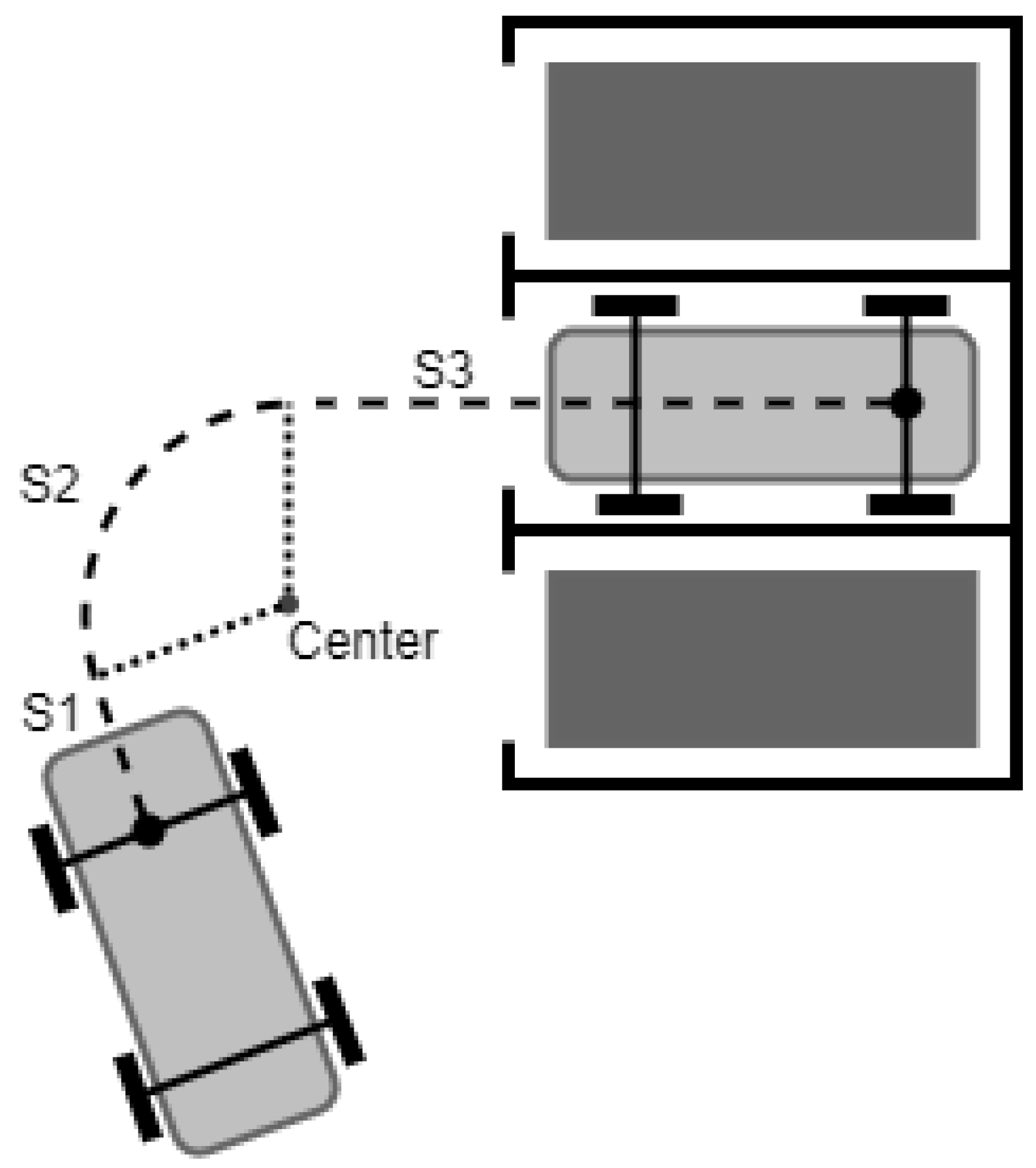
Figure 9.
pipeline latency analysis.
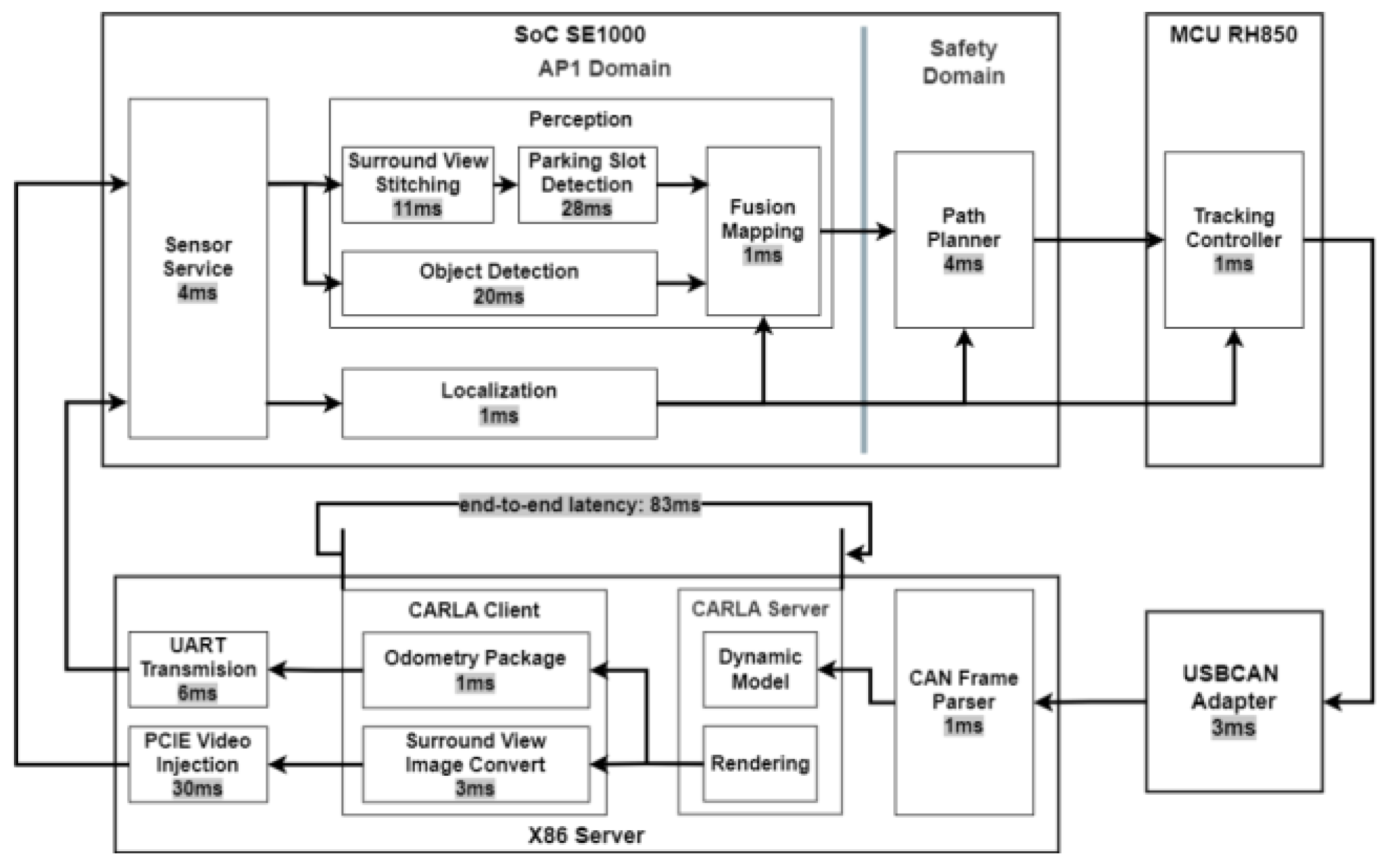

Table 1.
Specifications of the devices.
| Device | Model | Specification |
|---|---|---|
| X86 Server | DELL® Precision 5820 |
CPU: Intel® Core i9-10900X GPU: NVIDIA® RTX A4000 |
| PCIE Video Injection Card | ALINX® S2 | 3840 × 2160@30fps support up to 8-way output |
| USBCAN Adapter | iTekon® CANFD-X200 |
Dual Channel CANFD up to 5Mbps |
| SoC | SiEngine® SE1000 |
CPU: 4xA76 and 4xA55 GPU: GPU0 up to 625 GFLOPS, GPU1 up to 250 GFLOPS NPU: NPU0 up to 3.6 TOPS, NPU1 up to 3.5 TOPS Safety Processor: 1xR52 |
| MCU | Renesas® RH850U2A16 |
Quad 32-bit Core |
| Deserializer | MAXIM® MAX96722 |
Quad GMSL2 to CSI-2 |
Table 2.
Parameters of vehicle kinematic model.
| Params | Mini Cooper S |
|---|---|
| Mass | 1130.00 kg |
| Length | 3.80 m |
| Width | 1.97 m |
| Height | 0.74 m |
| Wheel Diameter | 37.50 cm |
| Wheelbase | 2.51 m |
| Axle Track | 1.56 m |
| Max Steer Angle | 70 degrees |
| Throttle Dead Zone | 0.15 |
Table 3.
Sensor Configuration.
| Sensor | Config |
|---|---|
| Camera Forward | 1920x1080, UYVY, FOV 120° |
| Camera Left | 1920x1080, UYVY, FOV 120° |
| Camera Rear | 1920x1080, UYVY, FOV 120° |
| Camera Right | 1920x1080, UYVY, FOV 120° |
| Odometry | Location, Rotation, Velocity, Angular Velocity |
Table 4.
APA simulation performance.
| Metric | Result |
|---|---|
| Maximum Search Range (m) | 8.0 |
| Parking Lots Detection Rate | 100% |
| Parking Success Rate | 100% |
| Average Parking Time (sec) | 57.0 |
| Average Number of Gear Changes | 0.33 |
| Average Displacement Error (m) | 0.02 |
| Average Orientation Error (degree) | 2.5 |
Disclaimer/Publisher’s Note: The statements, opinions and data contained in all publications are solely those of the individual author(s) and contributor(s) and not of MDPI and/or the editor(s). MDPI and/or the editor(s) disclaim responsibility for any injury to people or property resulting from any ideas, methods, instructions or products referred to in the content. |
© 2025 by the authors. Licensee MDPI, Basel, Switzerland. This article is an open access article distributed under the terms and conditions of the Creative Commons Attribution (CC BY) license (http://creativecommons.org/licenses/by/4.0/).
Copyright: This open access article is published under a Creative Commons CC BY 4.0 license, which permit the free download, distribution, and reuse, provided that the author and preprint are cited in any reuse.


