
Submitted:
05 June 2023
Posted:
07 June 2023
You are already at the latest version
Abstract
Since large articulated vehicles have uncertainties in trailer articulation angle as well as dynamic complexity, it is not easy to accurately establish a reliable motion plan. In this paper, two geometric path plans constructed based on the empirical rules of driving experts are presented so that articulated vehicles can automatically perform perpendicular parking on a reverse path. By analyzing the empirical parking methods of professional drivers, these path plans were constructed by appropriately combining several standardized simple basic motions to facilitate implementation in real vehicles. In addition, path plans included appropriate complementary motions to effectively respond to uncertainties arising from articulation angles, etc. The complementary motions developed in this study are based on the results of qualitative analysis on the behavior of articulated vehicles. The usefulness of the proposed articulated vehicle parking method has been proven through hundreds of experimental tests using a 1:10 ratio model automated vehicle.
Keywords:
large articulated vehicles
; automated perpendicular parking
; geometric path plans
; empirical methods
; articulation angles
; qualitative kinematics
; uncertainties
1. Introduction
Research and development works of automated driving for large articulated vehicles have been actively carried out until recently, but it is considered to be somewhat insufficient compared to passenger cars in the field of automated parking. Perpendicular parking of large articulated vehicles is usually done in reverse, and it is not an easy operation even for experienced drivers. Space and visibility problems due to vehicle size, non-linearities related to kinematic structures, and uncertainties in articulation joints aggravate parking difficulties.
Research works to solve the difficulties of driving a large articulated vehicle different from that of a passenger car have been continued for a long time. Xia et al. [1] suggested a control method to prevent dangerous phenomena such as jack knifing from occurring while driving a large articulated vehicle and demonstrated it using a real vehicle. In recent years, large articulated vehicles have become larger and longer, and face the problem of off-tracking, which is the difference in the path radius between the vehicle's front and rear axles during steering. Jogi et al. [2] suggested a way to improve this off-tracking problem. Li et al. [3] suggested a way to optimize the trajectory of articulated vehicles in the presence of obstacles. Fuzzy theory is widely used to realize automated parking of articulated vehicles. Moran [4], Azadi et al. [5], and Aye et al. [6] proposed a parking path plan based on the Fuzzy inference method.
Han [7] developed a method to analyze the post-collision behavior of a vehicle with only qualitative data in a vehicle collision accident with high uncertainty. He presented the inference results about the collision behavior of a vehicle based on the qualitative vector and qualitative mechanics theory. Wach et al. [8] also confirmed the need to include the uncertainty problem in calculations related to vehicle collision dynamics, and suggested various error analysis methods. González-Cantos et al. [9] presented a method for analyzing and designing an automated driving control system for articulated vehicles based on the qualitative theory of a nonlinear dynamic system. Xu et al. [10] proposed a motion plan system that considers the uncertainty of the vehicle itself and the surrounding environment in automated driving. Recently, Pamučar et al. [11] dealt with the uncertainty conditions that drivers face when determining the optimal route. In order to respond to the uncertainty in the behavior of the target vehicle as described above, qualitative reasoning can be effectively utilized.
On the other hand, in order to cope with the complexity of vehicle behavior, qualitative rules or expert systems based on actual driving experience are developed. Uttendorf et al. [12], Maeda [13], and Nine et al. [14] developed an expert system for automated driving. In particular, Brown et al. [15] presented a method to extract and quantify the driving skills of experts in driving large articulated vehicles from stored dynamic data.
Using a geometric method to plan a path related to automated parking of a vehicle is very intuitive and a concise way to implement the path. In this regard, Choi et al. [16], Petrov et al. [17], Wang et al. [18], and Oliveira et al. [19,20] proposed a parking path based on a geometric method. These geometric methods usually utilize the shortest curve path between two points solved by Dubins [21] and an optimal algorithm [22] that considers both the forward and backward paths of the vehicle by extending it to a practical problem. It is easy to implement a parking motion plan based on a geometric method that is composed by appropriately combining several standardized simple basic motions. Recently, Han [23] presented perpendicular and parallel parking path plans for a passenger car that can be applied even in a narrow space based on this geometric method.
In this study, two geometric path plans constructed based on the empirical rules of driving experts to automatically perform perpendicular parking for a large articulated vehicle as a reverse path are presented. In addition, the proposed standardized path plan added complementary actions based on the results of qualitative analysis on the behavior of the articulated vehicle to effectively respond to the uncertainty arising from the articulation angle. As far as the author is aware, there is no case of applying a geometric method based on qualitative reasoning or empirical rules of driving experts to automated parking of large articulated vehicles. In addition, the concept of complementary motion to overcome problems such as the kinematic uncertainty of articulated vehicles is considered a new attempt in the field of automated driving.
2. Geometric Parking Paths Based on Driver Experience
In this study, the typical parking path performed by drivers of large articulated vehicles was simplified to a geometric method based on a combination of straight lines and circles. During the parking process, steering of the vehicle was considered to be performed in a stationary state. Here, it is very important to form an appropriate articulation angle before the tractor starts turning 90° into the parking spot with the trailer using the minimum turning radius. The method of forming the required articulation angle in the actual parking motion of drivers can be divided into two types: backward or forward adjustment. Meanwhile, as in most geometric methods, unit motions of the vehicle in parking are classified into six: straight forwards (), straight backwards (), left-steering forwards (), left-steering backwards (), right-steering forwards (), and right-steering backwards (). Here, each motion is expressed as a single character with a superscript that expresses forward and backward [23].
2.1. Backward Adjustment Path: Articulation Angle Created by () Motion
The backward adjustment path shown in Figure 1 was constructed based on the large trailer license test process [24] filmed using a drone. This path is used when the vertical distance () from the parking spot is large because the vehicle cannot approach the parking spot due to obstacles. It is also used by driving experts, but it is usually the recommended parking method for beginners. The difference from the forward adjustment path described below is to secure the proper articulation angle of the trailer by using the backward motion () before entering the parking spot.
First, at a point that does not reach the parking spot, the left parking spot is searched with motion. After detecting the parking spot, it moves forward to the proper point by passing the parking spot to secure space for the subsequent backward path (). The vehicle directs the trailer towards the parking spot while increasing the articulation angle in motion. In order to prevent the risk of excessively large articulation angle, motion and motion are performed to properly form the articulation angle and the trailer is directed toward the center of the parking spot. When it is recognized that the articulation angle is within the appropriate range, it attempts to enter the parking spot with 90° motion. Finally, when it is confirmed that the vehicle is aligned in the parking spot with this motion, if necessary, the parking in the spot is finished through motion. If the trailer is not aligned before performing motion, it can be corrected with an additional complementary motion described later.
2.2. Forward Adjustment Path: Articulation Angle Created by () Motion
In the parking path [25] shown in Figure 2, an experienced driver usually starts parking at a point where the distance () from the parking spot is relatively short. Therefore, a smaller surrounding space for parking is required than the aforementioned backward adjustment. Here, an appropriate trailer articulation angle is secured using the forward motion () motion before entering the parking spot. In the actual parking video [25], steering is performed during operation according to the driver's discretionary judgment, but in this study, steering of the vehicle is performed only in a stationary state.
First, the left parking spot is searched with motion. After detecting the parking spot, it passes the parking spot and performs motion. After the tractor has turned about 60-80°, it makes the tractor parallel to the entrance of the parking spot by using the motion in the opposite direction. Here, with the motion, the articulation angle is reduced, but the direction of the tractor can be the same as the initial one. When it is recognized that the articulation angle is within the appropriate range by increasing the articulation angle again with motion, it attempts to enter the parking spot with 90° motion. Finally, when it is confirmed that the vehicle is aligned in the parking spot with this motion, parking is completed in the spot with the motion. If the posture of the trailer is inadequate because the articulation angle secured before performing motion is insufficient or excessive, the posture can be corrected with additional complementary motions.
3. Path Planning for Automated Perpendicular Parking
As shown in Figure 3, the initial posture of the large articulated vehicle is set to be positioned perpendicular to the parking spot on the left. As described above, according to the method of forming an appropriate articulation angle for entering the parking spot, the parking path is divided into two types: backward or forward adjustment, and a detailed path plan is prepared for each.
3.1. Parking Path Planning for Backward Adjustment ()
3.1.1. 90°𝐿− Motion for Access to Parking Spot ()
As shown in Figure 4, when the drivers start entering the parking spot backwards, they steer the tractor to the maximum to make a 90° turn while reducing the articulation angle (). Therefore, an appropriate articulation angle must be secured before starting this motion. As shown in Figure 5 based on PC-Crash simulation analysis results, the parameters that have the greatest influence on the size of this articulation angle are the turning radius of the tractor () and the trailer wheelbase (). It is known that the turning radius of the latest articulated vehicle tractor is about 6-7m. It was confirmed that the required articulation angle increased as the turning radius () was smaller and the trailer wheelbase () was longer. Also, within the ±3° error range of the required articulation angle, successful parking was usually possible in this study.
3.1.2. 𝑅−𝐿−(𝑆−) Motion for Required Articulation Angle ()
In Figure 6(a), is the motion to move the rear part of the trailer toward the parking spot, assuming that the parking spot is located on the left side of the vehicle. The articulation angle can be greatly increased through motion, but proper restriction of motion is necessary because jack knifing may occur. Professional drivers usually turn the tractor 40-50° to create an articulation angle and point the rear of the trailer towards the parking spot. In this study, the motion is limited to 45°. Then, as shown in Figure 6(b), motion is performed in the opposite direction to the motion so that the tractor is again perpendicular to the parking spot. Figure 7 shows the articulation angle after () motion by changing the trailer wheelbase () at specific turning radii (). As the turning radius () is longer and the trailer wheelbase () is shorter, the articulation angle () increases. In particular, it should be noted that the shorter the trailer wheelbase, the sharper the articulation angle increases as the turning radius increases.
On the other hand, if the proper articulation angle is not secured after () motion, motion can be optionally added. The tractor will then remain perpendicular to the parking spot, increasing the articulation angle. As the trailer wheelbase is longer, the required articulation angle before starting 90° motion increases (Figure 5), but the articulation angle created by () motion decreases (Figure 7). Therefore, motion distance will increase. Figure 8 shows the relationship between the travel distance of motion and the created articulation angle, and the movement distance increases in proportion to the trailer wheelbase (). On the other hand, if the articulation angle is small near 0°, the articulation angle changes insignificant even after the motion, so the initial articulation angle was set to 10°.
3.1.3. 𝑆 + Motion for Appropriate Subsequent Motions ()
In case of navigating the parking spot with backward movement, unintentional articulation angle may occur due to unstable movement of the trailer. Therefore, it is appropriate to determine whether parking is possible by searching the surrounding space and parking spot through forward movement.
As shown in Figure 9, the motion distance is estimated based on the point where the center of the rear wheel of the tractor is located on the center line of the parking spot. Depending on the length of the trailer, the number of axles, the center of gravity of the cargo, and the direction of the tractor of () motion, the travel distance may be slightly different. This backward adjustment requires more motion distance than the forward adjustment due to backward motions. By summing the radius of rotation, motion distance, and the linear distance of () motion, the motion distance can be obtained by Equation (1).
On the other hand, the minimum size of the surrounding space for the backward adjustment path can also be estimated from Figure 10. As shown in Equation (2), the X-axis minimum distance was calculated considering the motion and the Y-axis minimum distance was calculated considering the motion path.
3.2. Parking Path Planning for Forward Adjustment ()
3.2.1. Motion for Required Articulation Angle ()
90° motion in forward adjustment is the same as in backward adjustment described above. However, in order to form the same articulation angle, the forward adjustment () motion (Figure 11) is required to be larger than the backward adjustment () motion. Accordingly, more surrounding space is also required. In this study, the motion was set to 65°. After that, the tractor rotates in the opposite direction at the same angle with motion so that the tractor is again perpendicular to the parking spot. Figure 12 shows the articulation angle after () motion. As the turning radius () is longer and the trailer wheelbase () is shorter, the articulation angle () increases somewhat. However, unlike in the backward adjustment, when the trailer wheelbase is shortened, it can be seen that the articulation angle is generally insensitive to the change of the turning radius.
On the other hand, as in the backward adjustment, if an appropriate articulation angle is not secured after () motion, motion can be added here as well.
3.2.2. Motion for Appropriate Subsequent Motions ()
Unlike in the backward adjustment, the distance of () motion to create the articulation angle for the motion starting to enter the parking spot is not included in the motion, so the vehicle will travel a shorter distance as shown in Equation (3) (Figure 13).
On the other hand, the minimum size of the surrounding space for the forward adjustment path can also be estimated from Figure 14. As shown in Equation (4), the X-axis minimum distance was calculated considering the motion, and the Y-axis minimum distance was calculated considering the motion path.
4. Complementary Motions in Response to Uncertainties
According to the analysis of the parking behavior of an actual large articulated vehicle and the experimental results of the model articulated vehicle conducted in this study, there is uncertainty due to unavoidable errors in various motions of the vehicle as well as in the articulated joint. Such uncertainty may cause a situation that makes it difficult to successfully park in the final stage of parking, as shown in the typical examples in Figure 15.
It is very difficult for even experienced drivers to align the trailer into the parking spot at once without changing the steering while driving. Therefore, drivers must make a complementary motion during entry, usually before the trailer collides with an obstacle or when the trailer is not heading at the desired angle. In the position shown in Figure 15, the tractor moves forward to move the trailer away from obstacles or align with the parking spot. This principle is similar to the process in which the angle of the coupler link changes when the slider moves in the slider crank dealt with in the study of Ha et al. [26]. In addition, the same principle is adopted in the process of establishing the motion plan of the mechanical snake robot proposed by Shan et al. [27].
In the situations shown in Figure 15, the trailer may collide with an obstacle if the tractor continues in motion. Therefore, as in Figure 15(a), once the trailer is aligned with the parking spot, it immediately stops and then performs complementary motion. And, as shown in Figure 15(b), when the trailer is not aligned with the parking spot and a right-hand collision is expected, the trailer is first aligned with the parking spot through the supplementary motion after stopping, and the subsequent supplementary motion is performed.
However, in order to plan an efficient complementary motion, a qualitative analysis [7] of vehicle behavior according to the vehicle's forward/backward steering and articulation angle is required. In this study, as shown in Figure 16, the steering angle and the articulation angle were divided into three directions, respectively. The results of the qualitative change of the trailer articulation angle according to the forward and backward steering motion of the tractor were confirmed through kinematic intuition and repeated PC-Crash simulations and summarized in Table 1 and Table 2. Qualitative changes in trailer articulation angle were classified into three categories: increase (↑), decrease (↓), and no change (↔). And, as described in the previous section, the backward motion results in a larger change in the articulation angle than the forward motion.
As shown in Table 1 and Table 2, the articulation angle generally increases in many cases in backward steering, whereas the number of cases in which the articulation angle decreases and increases in forward steering is equal. If a certain steering is continued in forward or backward motion, the sign of the articulation angle may change due to the continuous increase or decrease in the size of the articulation angle. The ability to generate articulation angle is relatively larger in the backward motion than in the forward motion.
In the situation of Figure 15(a), which shows a typical parking failure, the trailer has a negative articulation angle. This situation is usually caused by the articulation angle formed larger than necessary before 90° motion. In order to avoid an imminent collision, the first necessary policy is to stop the in-progress backward motion and change it to a forward motion. And as shown in Table 1, or motion is required to reduce the articulation angle. For tractor alignment, it is appropriate to select and perform motion. In this forward motion, the articulation angle of the trailer changes small compared to the amount of rotation of the tractor. In order to enter the parking spot again, a backward motion is required. In order to further reduce the articulation angle in the situation of still negative articulation angle, as shown in Table 2, motion must follow. This motion also helps to align the tractor. These series of complementary motions are shown in Figure 17.
On the other hand, the parking failure situation in Figure 15(b) is usually caused by the articulation angle formed smaller than necessary before 90° motion. In the motion process, before the tractor is aligned, the magnitude of the negative articulation angle decreases a lot, and uncertainty occurs such as the sign changes. Therefore, it is configured as shown in Figure 18(a) so that it responds to the uncertainty of the articulation angle by performing motion to have a positive articulation angle and the mirror posture identical to that of Figure 15(a). After that, as shown in Table 1, or motion is required to reduce the articulation angle. For tractor alignment, it is appropriate to select motion. Here too, the articulation angle of the trailer changes very small compared to the amount of rotation of the tractor. In the situation of still positive articulation angle, motion should follow as shown in Table 2 to decrease the articulation angle during backward motion to enter the parking spot. This is shown in Figure 18(b) as , which is the mirror motion of presented in Figure 17.
The end of the complementary motion corresponding to a left collision () or a complementary motion corresponding to a right collision () is confirmed by the alignment of the tractor and trailer inside the parking spot. If the vehicle alignment is still insufficient, it is possible to perform repetitive complementary actions. Finally, if necessary, the vehicle completes parking with the motion.
5. Experimental Test of Automated Parking
The path planning of the articulated vehicle was implemented through the model automated vehicle experiment. The tractor used in this study was Xycar-A3 [28], and the semi-trailer was directly manufactured with a variable wheelbase structure. The sensor that recognizes front obstacles and side parking spots is a front 1-channel lidar sensor (15cm to 18m range). The vehicle control uses the Vedder Electric Speed Controller (VESC) to drive the rear wheels and steer the front wheels. Nvidia TX2 is built into the vehicle, and automated parking was implemented using Robot Operating System (ROS). The tractor uses a BLDC drive motor and has a differential gear device. The trailer is framed using an aluminum profile, so that the wheelbase can be easily adjusted as needed. The axle of the trailer is made of ABS material using a 3D printer, and the wheels are the same as the tractor.
Table 3 summarizes the main dimensions of the experimental model vehicle, which is a 1:10 ratio of the actual vehicle. The width of the parking spot was set to 500mm, and obstacle walls were installed on both sides of the parking spot so that the lidar sensor could easily recognize it. On the other hand, previous studies [29,30,31,32] on large articulated vehicles also used a model tractor-trailer as in this study, and did not report any special differences from the actual vehicle in vehicle behavior and experimental results.
Figure 19 shows the successful experimental test results of backward adjustment perpendicular parking (). Here, an articulation angle suitable for entering the parking spot is formed through the backward motion (). In the figure, the length of one side of the floor block of the test site is 0.98 to 0.99 m. Even under the same conditions during the repeated experiment, there was a slight difference in the position where the lidar sensor recognized the parking spot and the moving distance for each operation of the parking process. Therefore, although misalignment often occurred when entering the parking spot, if it did not collide with a side obstacle and a collision is expected, successful parking can be completed through complementary motions.
Figure 20 shows the successful experimental results of forward adjustment perpendicular parking (). As shown in Figure 20(a), the articulation angle was formed through the forward motion (), and the articulation angle was increased as needed through the subsequent motion. Figure 20(b) shows entering the parking spot with a trajectory similar to that shown in Figure 19.
Figure 21 shows the initial posture and progress of the left-side complementary motion () performed when a collision with the left obstacle is expected if the parking motion continues (Figure 17). In the case of Figure 21(a), when the trailer is aligned at the parking spot, it stops and then starts complementary motion. The direction of the tractor varies depending on the situation, but the direction of the trailer is not changed and the direction of the tractor can be aligned by repeating complementary motion. As shown in Figure 21(b), the tractor performed forward () after maximum steering to the right and backward () after maximum steering to the left. At this time, almost the same forward and backward distances are not large, so the direction of the trailer hardly changes and the surrounding space is not used much.
Figure 22 shows the initial posture and process of right-side complementary motion () performed when a collision with an obstacle on the right is expected if the parking motion continues (Figure 18). In the situation of Figure 22(a), since the trailer is not aligned in the parking spot, it is set to stop before it collides with the obstacle on the right side of the parking spot. In this complementary motion, the angle at which the tractor must rotate increases, so the surrounding space required for parking increases.
Unlike left-side complementary motion, in a situation like Figure 22(a), the direction of the trailer must be corrected first. Therefore, as shown in Figure 22(b), align the trailer to the parking spot with motion. Then, as shown in Figure 22(c), the tractor can also be aligned in the parking spot by performing the mirror motion () corresponding to the left-side complementary motion (). Finally, if necessary, the vehicle completes parking with the motion.
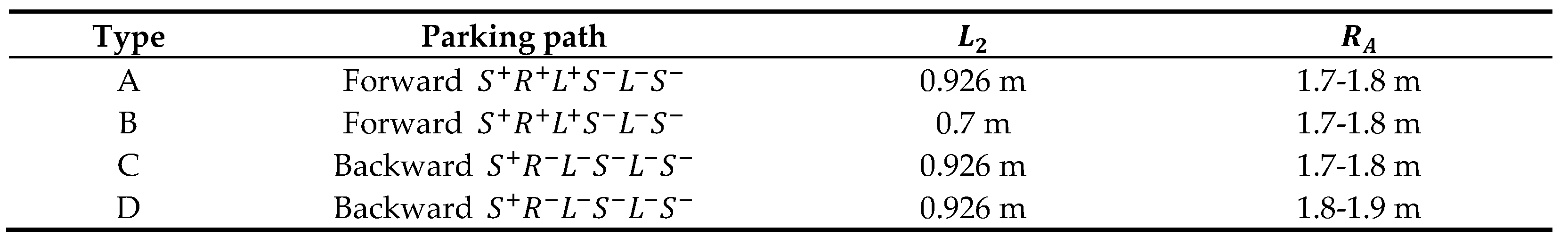
In this study, four types of experimental tests as shown in Table 4 were repeated 120 times, 30 times each. In the automated parking tests, it was judged to be successful when the vehicle completely entered the parking space without colliding with the obstacle wall. As shown in Figure 23, with the application of complementary motion, the success rate was 88.4%. The success rate by type was almost the same, but the success rate of type B with a short wheelbase () of the trailer was rather high. In addition, the failure rate of type D with a relatively long turning radius () was rather high. The parking time took 24-26 seconds when parking was completed without complementary motion after the lidar sensor recognized the parking spot. The left-side supplemental motion took 15-18 seconds, and the right-side supplemental motion took 19-22 seconds of additional time. The average number of repetitions of complementary motions was 1.8 and was limited to a maximum of 3 times. If the number of complementary operations is increased, most can be successful except in unavoidable cases due to problems such as vehicle performance, but excessive parking time may be required.
6. Conclusions
Since large articulated vehicles have uncertainties in trailer articulation angle as well as dynamic complexity, it is not easy to accurately establish a reliable motion plan. In this paper, two novel geometric path plans constructed based on the empirical rules of driving experts to automatically perform perpendicular parking for large articulated vehicles were presented. The typical parking operation performed by drivers of large articulated vehicles is simplified with a geometric method based on a combination of straight lines and circles. Here, it is very important to form an appropriate articulation angle before starting the 90° rotation motion of the final stage when the tractor enters the parking spot with the trailer using the minimum turning radius. According to the method of forming the necessary articulation angle in the actual parking motion of drivers, the parking path was divided into two types: backward adjustment or forward adjustment, and a detailed path plan was prepared for each. The path plan presented in this study is configured by appropriately combining several standardized simple basic motions, making it insensitive to the kinematic complexity and uncertainty of the vehicle, making it easy to implement the actual vehicle.
According to the analysis of the actual large articulated vehicle's parking behavior and the experimental results of the model articulated vehicle conducted in this study, there is uncertainty due to unavoidable errors in the operation of the vehicle during parking as well as in the articulated joint. Such uncertainty may cause a situation that makes normal parking difficult in the final stage of parking. In the path planning presented in this study, appropriate complementary motions were added to cope with the uncertainty arising from the articulation angle. The suggested complementary motion is based on the results of qualitative analysis on the behavior of articulated vehicles.
The usefulness of the automated parking method developed for articulated vehicles was proven through repeated experimental tests of 120 times, 30 times each of four types with a model automated vehicle in a ratio of 1:10. The parking test result was judged to be successful if the vehicle entered the parking spot without colliding with the parking spot obstacle wall. With the application of the suggested complementary motion, the parking success rate was 88.4%.
Funding
This work was supported by Basic Science Research Program through the National Research Foundation of Korea (NRF) funded by the Ministry of Education (NRF-2019R1I1A3A01057373).
Data Availability Statement
Not applicable.
Conflicts of Interest
The authors declare no conflict of interest.
References
- Xia, G.; Zhao, M.; Tang, X.; Wang, S.; Zhao, L. Linear reversing control of semi-trailer trains based on hitch angle stable and feasible domain. Control Engineering Practice. 2020, 104, 104625. [Google Scholar] [CrossRef]
- Jogi, A.; Chandramohan, S. Kinematic Analysis of tractor-semitrailer with split fifth wheel coupling during low speed turning maneuvers. SAE Int. J. Commer. Veh. 2017, 10, 582–588. [Google Scholar] [CrossRef]
- Li, B.; Shao, Z. An incremental strategy for tractor-trailer vehicle global trajectory optimization in the presence of obstacles. In IEEE International Conference on Robotics and Biomimetics (ROBIO), Zhuhai, China, 06-09 December 2015; pp. 1447–1452.
- Moran, A. Autonomous path following of truck-trailer vehicles using linear-fuzzy control. In 3rd International Conference on Control, Automation and Robotics (ICCAR), Nagoya, Japan, 24-26 April 2017; pp. 651–657.
- Azadi, S.H.; Nedamani, H.R.; Kazemi, R. Automatic parking of an articulated vehicle using ANFIS. Global Journal of Science, Engineering and Technology. 2013, 14, 93–104.
- Aye, Y.Y.; Watanabe, K. Image-based Fuzzy parking control. SYSTEMS, CONTROL AND INFORMATION. 2020, 64, 296–303.
- Han, I. Analysis of Vehicle Collision Accidents Based on Qualitative Mechanics. Forensic science international. 2018, 291, 53–61. [Google Scholar] [CrossRef] [PubMed]
- Wach, W.; Jan, U. Uncertainty of calculation results in vehicle collision analysis. Forensic science international. 2007, 167, 181–188. [Google Scholar] [CrossRef] [PubMed]
- González-Cantos, A.; Ollero, A. Backing-up maneuvers of autonomous tractor-trailer vehicles using the qualitative theory of nonlinear dynamical systems. The International Journal of Robotics Research. 2009, 28, 49–65. [Google Scholar] [CrossRef]
- Xu, W.; Pan, J.; Wei, J.; Dolan, J.M. Motion planning under uncertainty for on-road autonomous driving. In IEEE International Conference on Robotics and Automation (ICRA), Hong Kong, China , 31 May - 07 June 2014; pp. 2507–2512.
- Pamucar, D.; Goran, Ć. Vehicle route selection with an adaptive neuro fuzzy inference system in uncertainty conditions. Decision Making: Applications in Management and Engineering 2018, 1, 13–37. [Google Scholar] [CrossRef]
- Uttendorf, S.; Eilert, B.; Overmeyer, L. A fuzzy logic expert system for the automated generation of roadmaps for automated guided vehicle systems. In IEEE International Conference on Industrial Engineering and Engineering Management (IEEM), Bali, Indonesia , 04-07 December 2016; pp. 977–981.
- Maeda, M. Fuzzy drive expert system for an automobile. Information Sciences-Applications 1995, 4, 29–48. [Google Scholar] [CrossRef]
- Nine, J.; Manoharan, S.; Hardt, W. Concept of the comprehension level of situation awareness using an expert system. In IOP Conference Series: Materials Science and Engineering, 2021; 1019.1: p. 012103.
- Brown, J.; He, Y.; Lang, H. Quantifying drivers’ driving skills using closed-loop dynamic simulations of articulated heavy vehicles. Simulation Modelling Practice and Theory. 2020, 99, 102014. [Google Scholar] [CrossRef]
- Choi, S.; Boussard, C.; d'Andréa-Novel, B. Easy path planning and robust control for automatic parallel parking. IFAC Proceedings. 2011, 44, 656–661. [Google Scholar] [CrossRef]
- Petrov, P.; Nashashibi, F. Automatic vehicle perpendicular parking design using saturated control. In IEEE Jordan Conference on Applied Electrical Engineering and Computing Technologies (AEECT), Amman, Jordan, 03-05 November 2015; pp. 1–6.
- Wang, J.M.; Wu, S.T.; Ke, C.W.; Tzeng, B.K. Parking path programming strategy for automatic parking system. Vehicle Engineering (VE). 2013, 1, 57–63. [Google Scholar]
- Oliveira, R.; Ljungqvist, O.; Lima, P.F.; Wahlberg, B. Optimization-based on-road path planning for articulated vehicles. IFAC-PapersOnLine. 2020, 53, 15572–15579.
- Oliveira, R.; Ljungqvist, O.; Lima, P.F.; Wahlberg, B. A geometric approach to on-road motion planning for long and multi-body heavy-duty vehicles. In IEEE Intelligent Vehicles Symposium (IV), Las Vegas, NV, USA, 19 October - 13 November 2020; pp. 999–1006.
- Dubins, L.E. On curves of minimal length with a constraint on average curvature, and with prescribed initial and terminal positions and tangents. American Journal of mathematics. 1957, 79, 497–516. [Google Scholar] [CrossRef]
- Reeds, J.A.; Shepp, L.A. Optimal paths for a car that goes both forwards and backwards. Pacific journal of mathematics. 1990, 145, 367–393. [Google Scholar] [CrossRef]
- Han, I. Geometric path plans for perpendicular/parallel reverse-parking in a narrow parking spot with surrounding space. Vehicles. 2022, 4, 1195–1208. [Google Scholar] [CrossRef]
- Kim, M. Large towing (trailer) license drone video. Available online: https://www.youtube.com/watch?v=k9UMnn7RGXw (accessed on 28 Jan 2020).
- Weecks, D. Trailer Backing Tutorial by swift Academy. Available online: https://www.youtube.com/watch?v=O8I0OwRHzUQ (accessed on 26 Dec 2021).
- Ha, J.L.; Fung, R.F.; Chen, K.Y.; Hsien, S.C. Dynamic modeling and identification of a slider-crank mechanism. Journal of sound and vibration. 2006, 289, 1019–1044. [Google Scholar] [CrossRef]
- Shan, Y.; Koren, Y. Design and motion planning of a mechanical snake. IEEE transactions on systems, man, and cybernetics. 1993, 23, 1091–1100.
- Xytron Xycar-A3. Available online: http://xytron.co.kr/?page_id=502 (accessed on 13 February 2021).
- Rzydzik, S.; Saltarski, A.; Roziński, M.; Psiuk, K. Infrared distance sensors for autonomous model of truck with semi-trailer. In 6th International Conference on Mechatronics and Robotics Engineering (ICMRE), Barcelona, Spain, 12-15 February 2020; pp. 104–109.
- Khalaji, A.K.; Moosavian, S.A.A. Robust adaptive controller for a tractor–trailer mobile robot. IEEE/ASME Transactions on Mechatronics 2013, 19, 943–953. [Google Scholar] [CrossRef]
- Altafini, C.; Speranzon, A.; Wahlberg, B. A feedback control scheme for reversing a truck and trailer vehicle. IEEE Transactions on robotics and automation. 2001, 17, 915–922. [Google Scholar] [CrossRef]
- Parra-Loera, R.; Corelis, D.J. Expert system controller for backing-up a truck-trailer system in a constrained space. In 37th Midwest Symposium on Circuits and Systems (Vol. 2), Lafayette, LA, USA, 03-05 August 1994; pp. 1357–1361.
Figure 1.
() perpendicular parking path.
Figure 2.
() perpendicular parking path.
Figure 3.
Perpendicular parking of the large articulated vehicle.
Figure 4.
90° motion: (a) Start of 90° motion; (b) End of 90° motion.
Figure 5.
Required articulation angle before starting 90° motion.
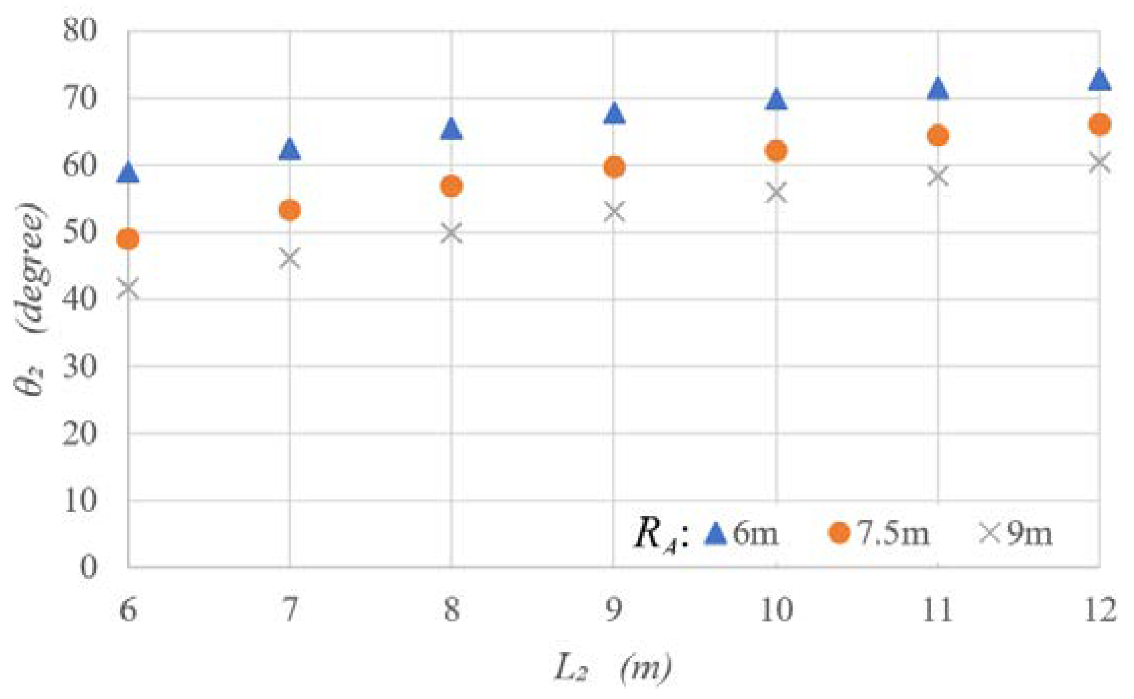
Figure 6.
() motion: (a) Start of () motion; (b) End of () motion.
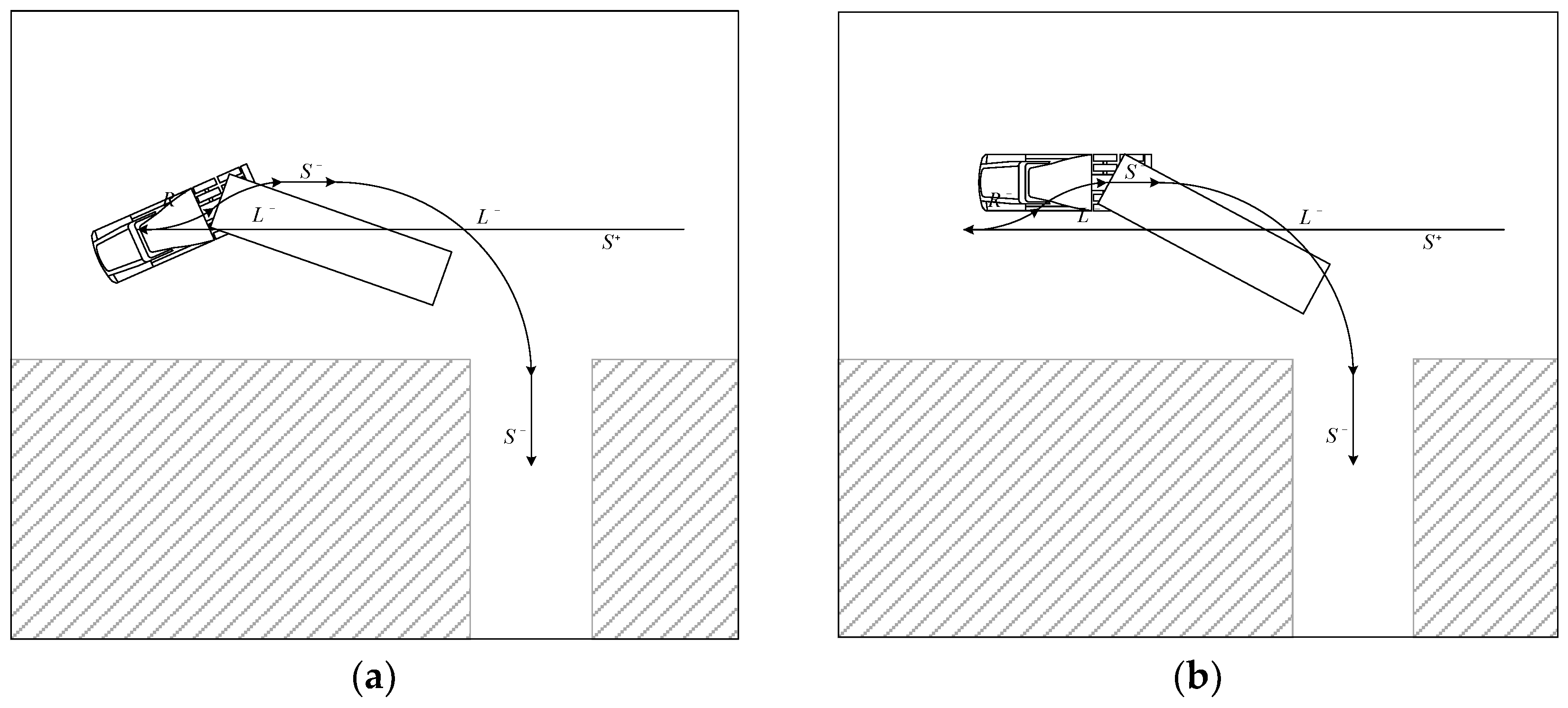
Figure 7.
Articulation angle after () motion.
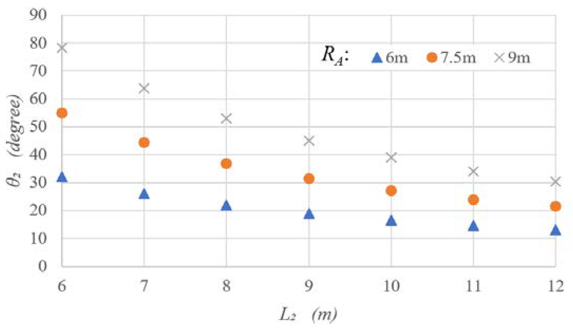
Figure 8.
Articulation angle according to motion travel distance (initial ).
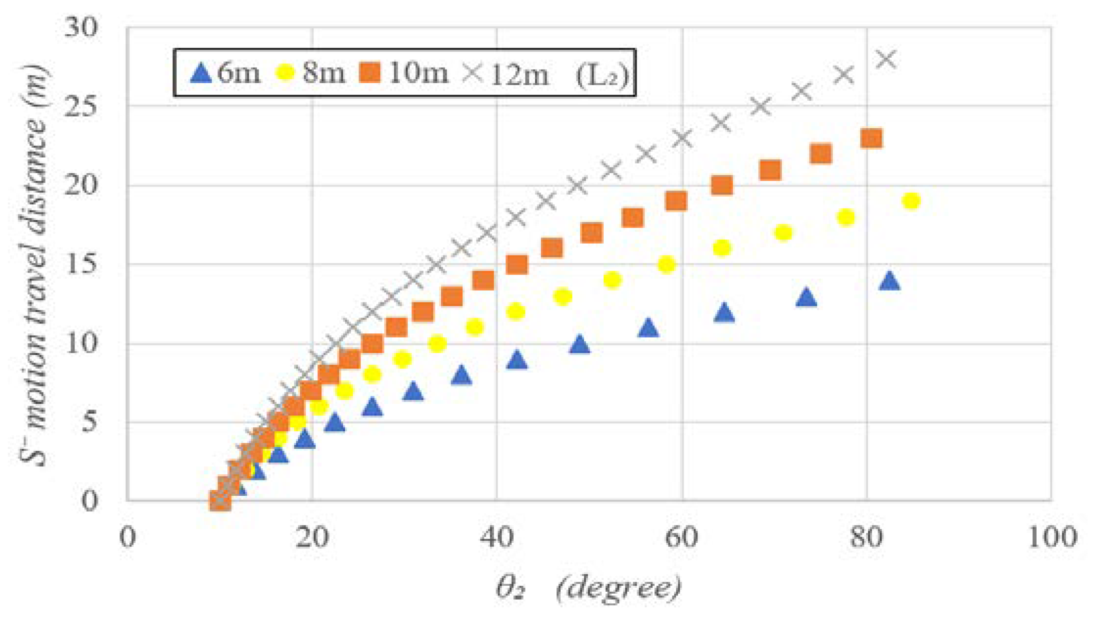
Figure 9.
Straight distance for motion in backward adjustment parking () : (a) Entire parking path; (b) Travel distances.
Figure 9.
Straight distance for motion in backward adjustment parking () : (a) Entire parking path; (b) Travel distances.
Figure 10.
Surrounding space for backward adjustment parking ().
Figure 11.
() motion: (a) Start of () motion; (b) End of () motion.
Figure 12.
Articulation angle after () motion.
Figure 13.
Straight distance for motion in forward adjustment parking (): (a) Entire parking path; (b) Travel distances.
Figure 13.
Straight distance for motion in forward adjustment parking (): (a) Entire parking path; (b) Travel distances.
Figure 14.
Surrounding space for forward adjustment parking ().
Figure 15.
Typical parking failure cases at the final stage (): (a) Predicted collision on the left side; (b) Predicted collision on the right side.
Figure 15.
Typical parking failure cases at the final stage (): (a) Predicted collision on the left side; (b) Predicted collision on the right side.
Figure 16.
Qualitative representation of vehicle steering angle and articulation angle.
Figure 17.
Complementary motion () against collision on the left side: (a) motion; (b) motion.
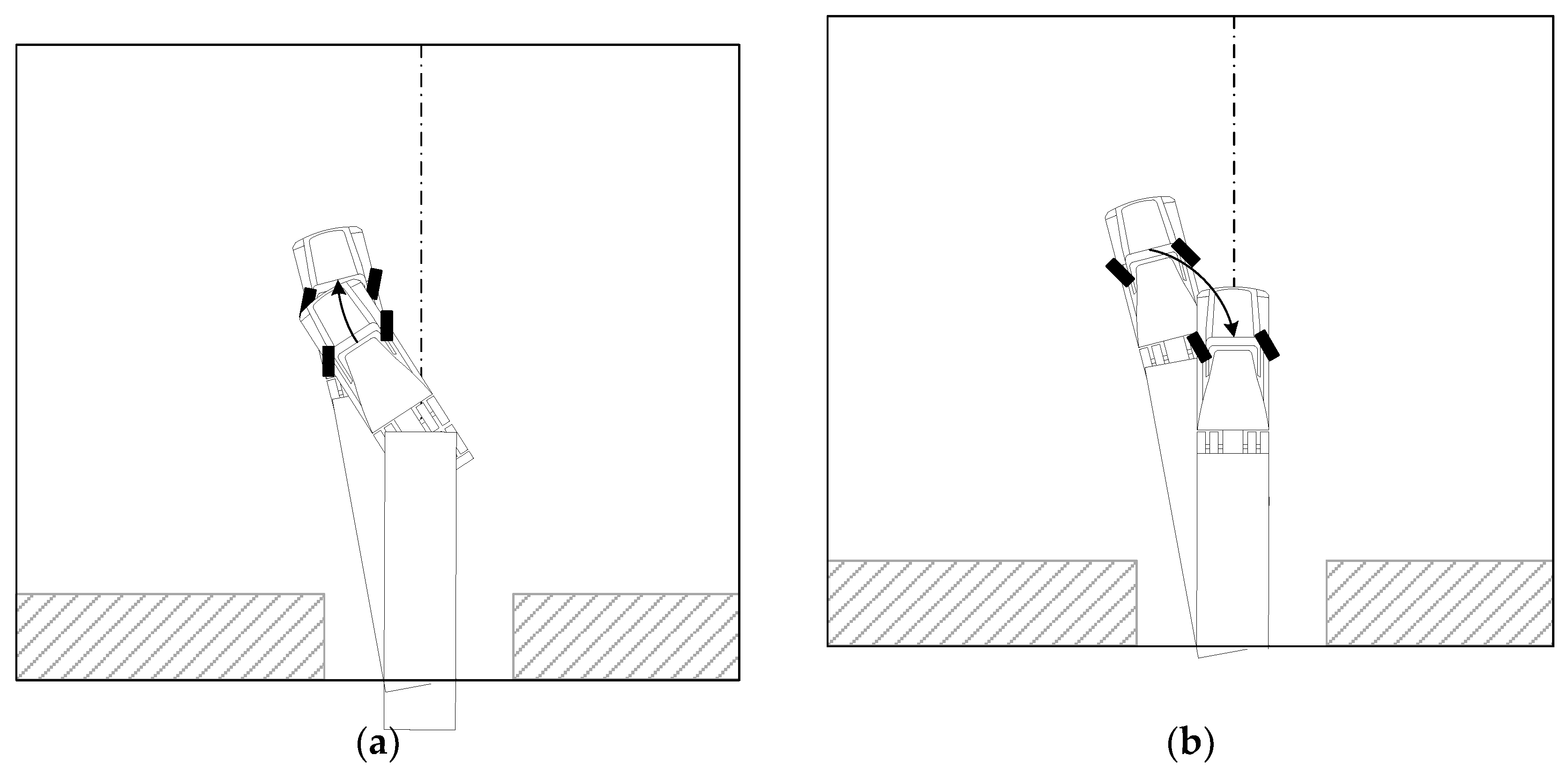
Figure 18.
Complementary motion () against collision on the right side: (a) motion; (b) () motion.
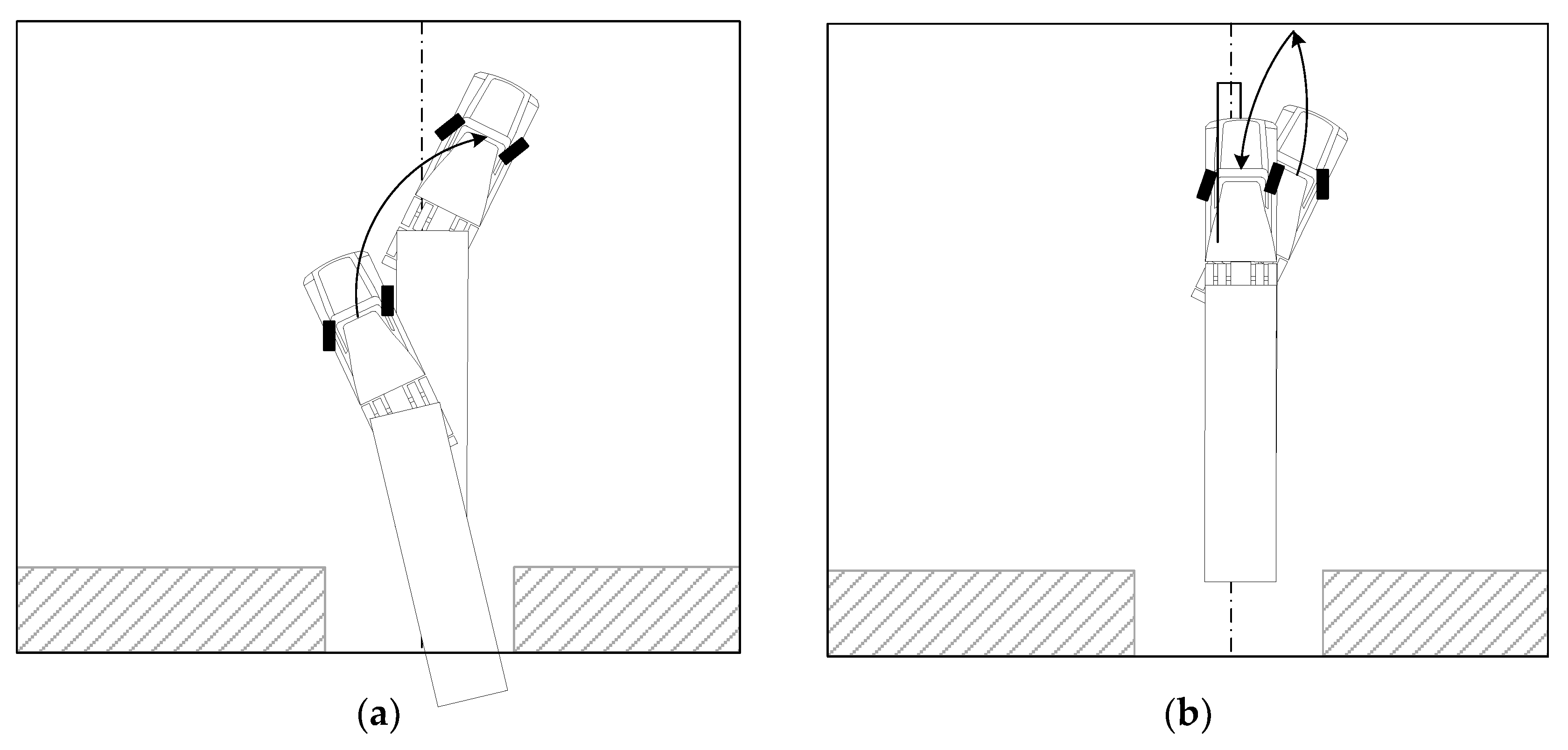
Figure 19.
Backward adjustment () perpendicular parking (Type C).
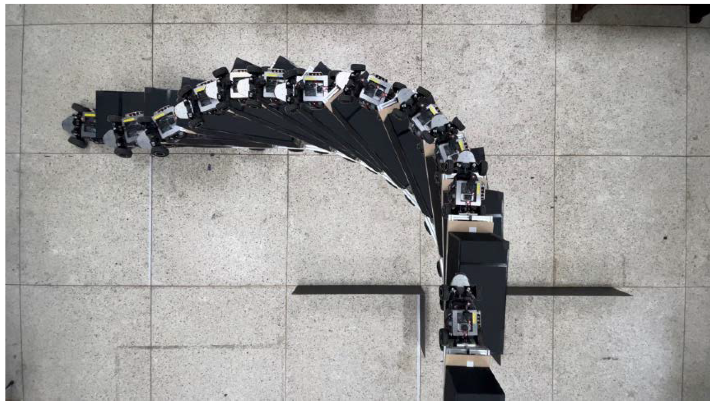
Figure 20.
Forward adjustment () perpendicular parking (Type A): (a) () motion; (b) () motion.
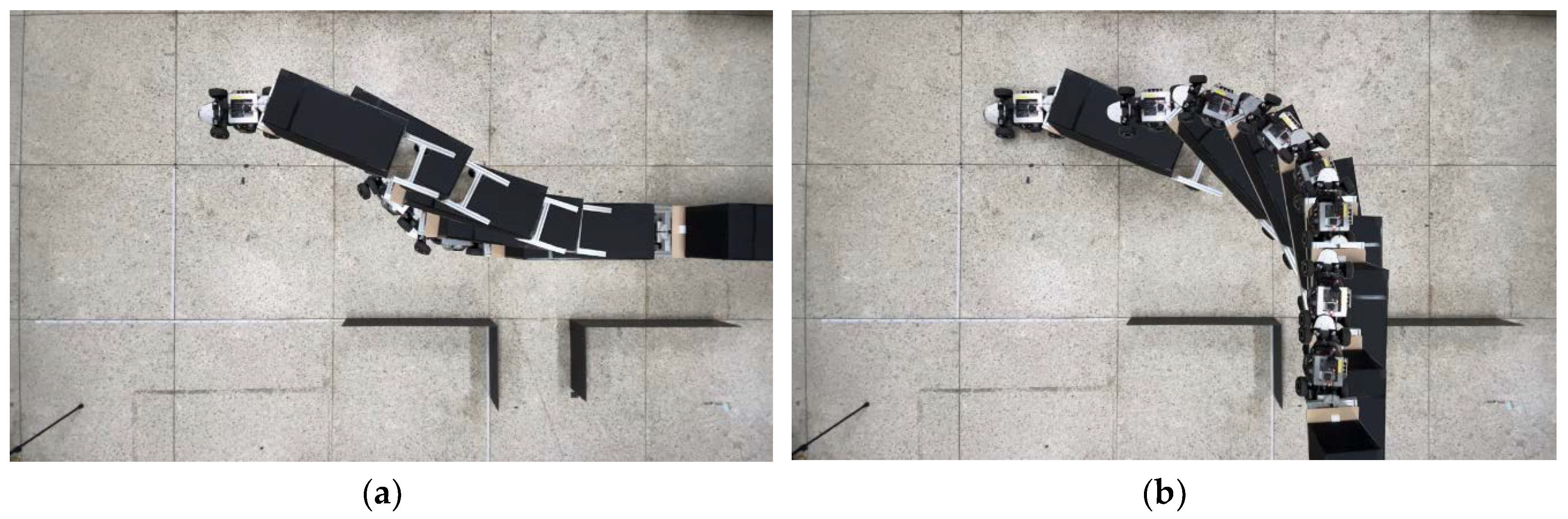
Figure 21.
Left-side complementary motion () against collision on the left side (Type C): (a) Start of left-side complementary motion; (b) Left-side complementary motion ().
Figure 21.
Left-side complementary motion () against collision on the left side (Type C): (a) Start of left-side complementary motion; (b) Left-side complementary motion ().
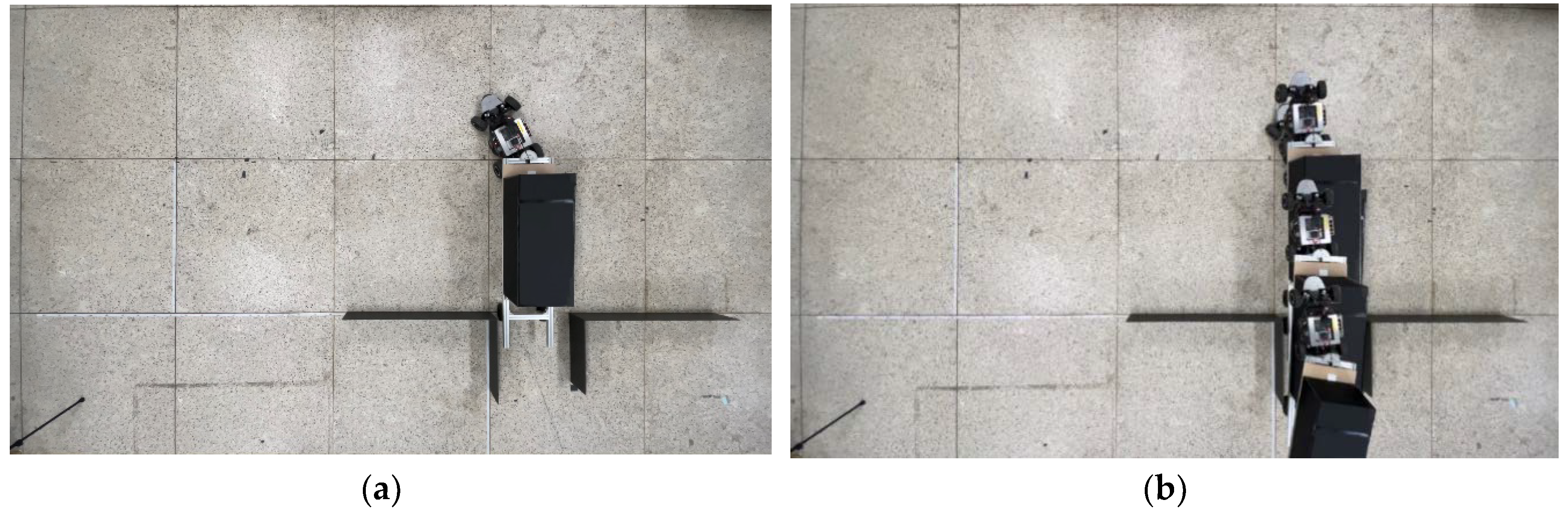
Figure 22.
Right-side complementary motion () against collision on the right side (Type A): (a) Start of right-side complementary motion; (b) Right-side complementary motion (); (c) Right-side complementary motion ().
Figure 22.
Right-side complementary motion () against collision on the right side (Type A): (a) Start of right-side complementary motion; (b) Right-side complementary motion (); (c) Right-side complementary motion ().
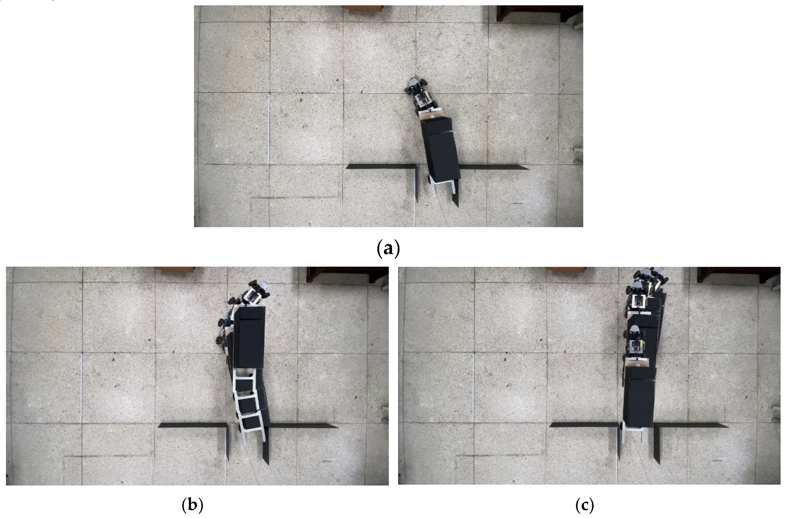
Figure 23.
Success rate of parking experimental tests (including complementary motions).
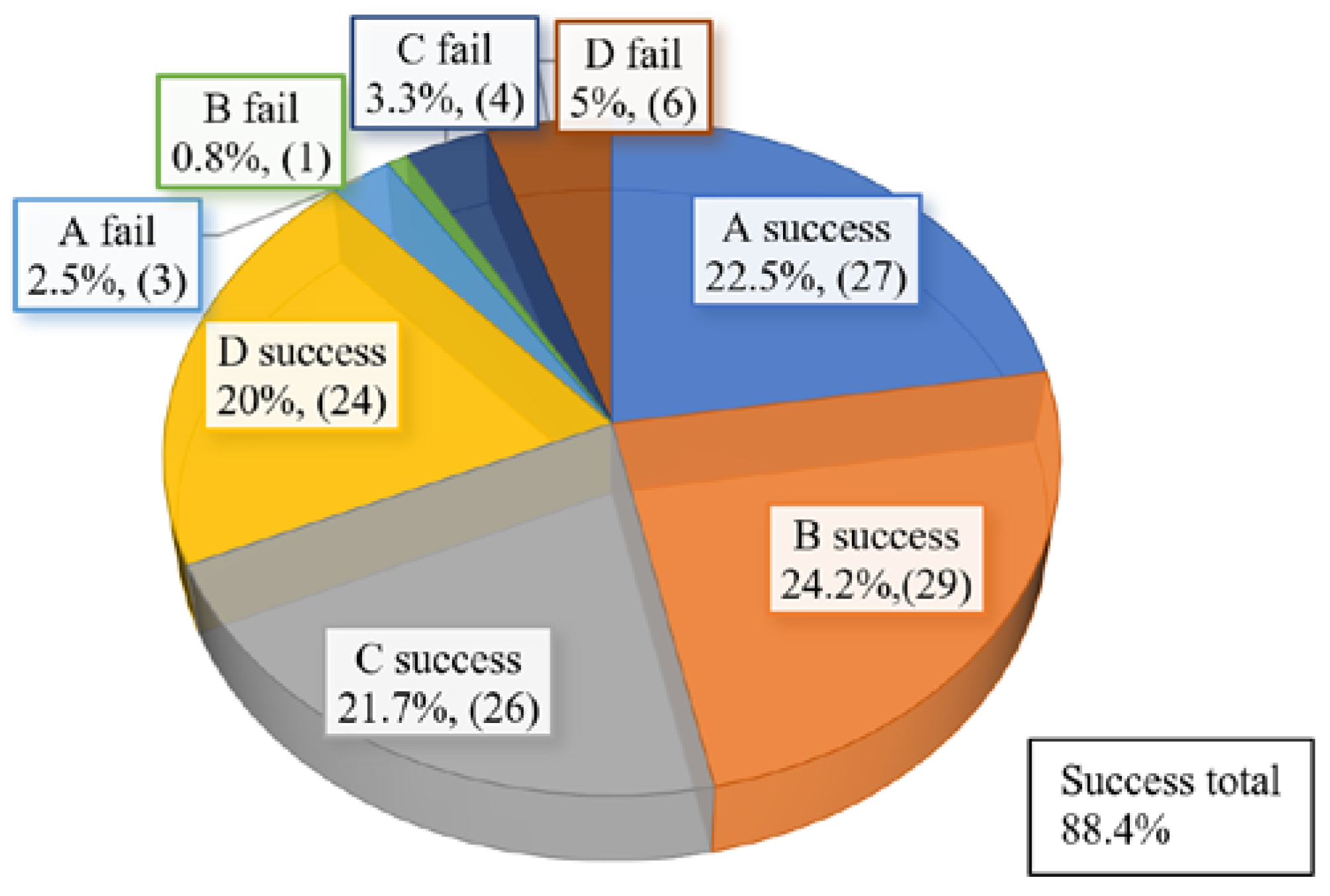

Table 1.
Qualitative change of articulation angle magnitude due to steering forwards.
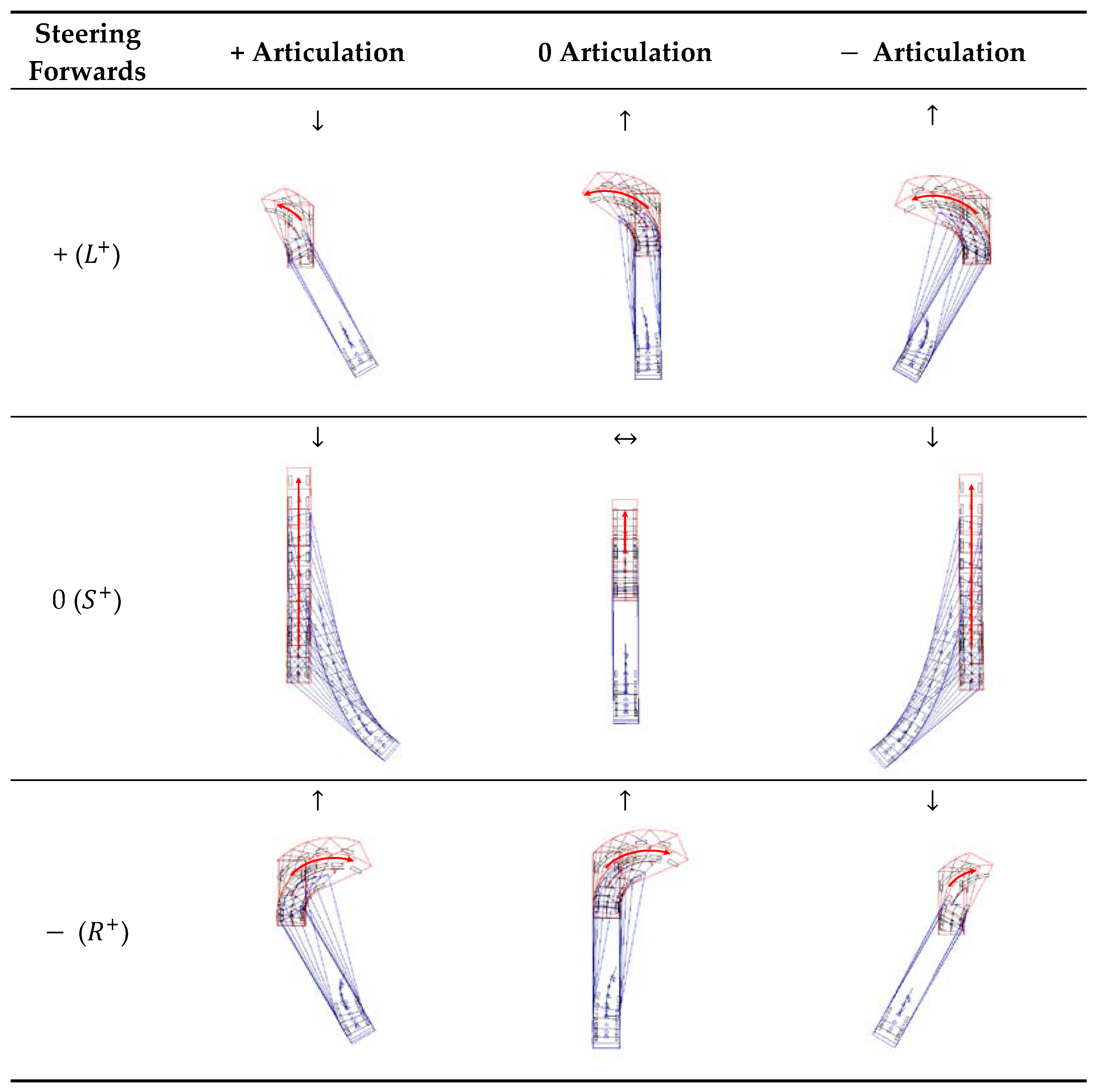
Table 2.
Qualitative change of articulation angle magnitude due to steering backwards.
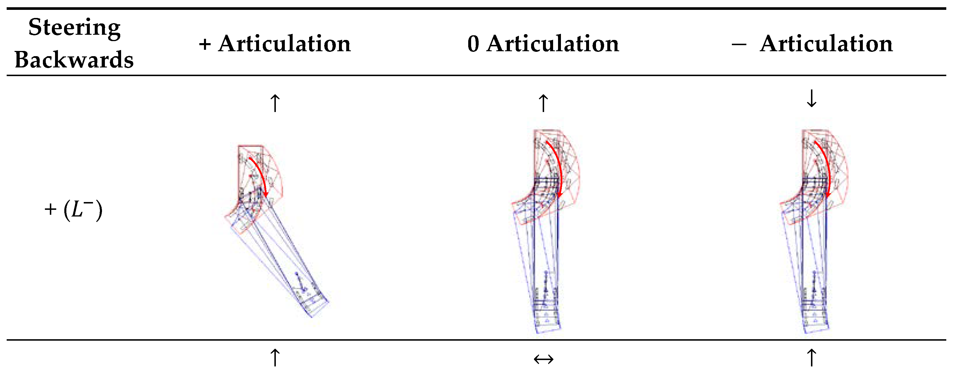
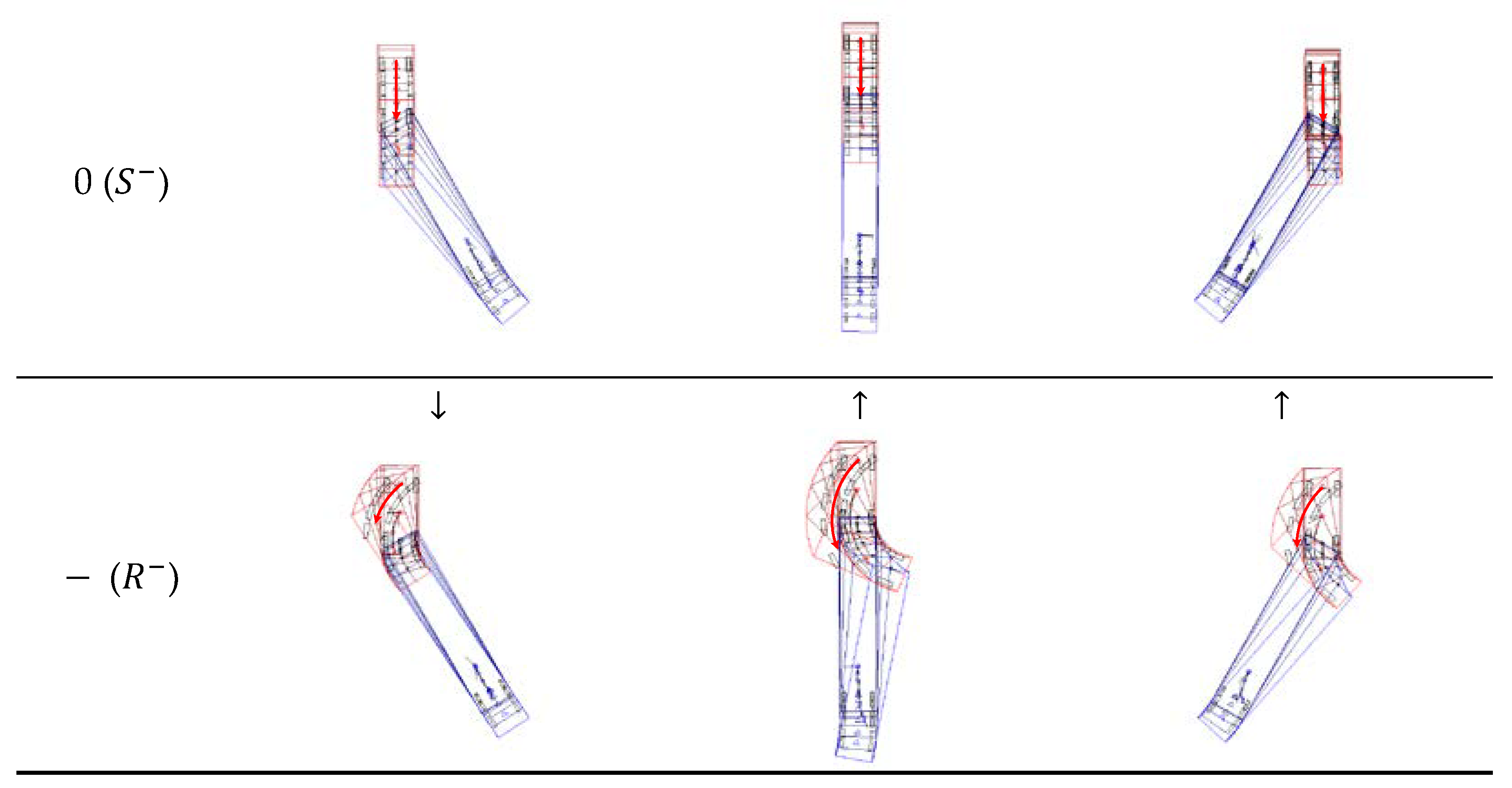
Table 3.
The model car dimensions.
| Vehicle (mm) | Overall length | Overall width | Wheelbase | Turning radius |
|---|---|---|---|---|
| Tractor | 768 | 290 | 333 | 1700 |
| Trailer | 1120 | 290 | 200-1115 |
Table 4.
Scenarios for parking experimental tests.
Disclaimer/Publisher’s Note: The statements, opinions and data contained in all publications are solely those of the individual author(s) and contributor(s) and not of MDPI and/or the editor(s). MDPI and/or the editor(s) disclaim responsibility for any injury to people or property resulting from any ideas, methods, instructions or products referred to in the content. |
© 2023 by the authors. Licensee MDPI, Basel, Switzerland. This article is an open access article distributed under the terms and conditions of the Creative Commons Attribution (CC BY) license (http://creativecommons.org/licenses/by/4.0/).
Copyright: This open access article is published under a Creative Commons CC BY 4.0 license, which permit the free download, distribution, and reuse, provided that the author and preprint are cited in any reuse.


