
Submitted:
20 May 2025
Posted:
21 May 2025
You are already at the latest version
Abstract
In this paper, a printed hybrid-mode antenna for dual band circular polarization (CP) is proposed. In the proposed antenna, one T-shaped element is fed by a coplanar waveguide and one L-shaped element is loaded to ground plane. The relationship between the antenna geometric parameters and the circular polarization characteristic (axial ratio) is examined through electric current distribution and radiation field components. In addition, the antenna's resonant modes are being investigated by Characteristic Mode Analysis (CMA). Through parametric studies, the range of two frequency ratios is explored, revealing that the antenna operates as a dual-band single-sense CP antenna even in ranges where the two frequency ratios (the ratio of high frequency to low frequency) are smaller compared to antennas in other literature. The proposed antenna has a frequency ratio of less than 1.5 between the two frequencies and can be flexibly designed. The proposed antenna is designed for 2.5 GHz band and 3.5 GHz band. The measured bandwidths of 10 dB-impedance with a 3 dB-axial ratio are 2.35 GHz - 2.52 GHz and 3.36 GHz - 3.63 GHz, respectively.
Keywords:
hybrid-mode
; dual-band single-sense circular polarization
; circularly polarized antenna
; characteristics mode analysis
1. Introduction
Many applications such as Sub-6GHz 5G, IoT communication and applications in IMS band are used in the frequency band below 6 GHz. In this situation, dual-band antennas are very effective in ensuring wide coverage and compatibility with different communication standards, as well as in reducing the size and cost of antennas. In addition, the use of circularly polarized waves allows greater freedom in antenna installation orientation, and from the perspective of improving communication quality in multipath environments, dual-band circularly polarized antennas are expected to play an important role in future mobile communication systems.
In dual-band printed antenna for CP, there are two types of polarization sense, single sense [1,2,3,4,5,6] and dual sense [7,8,9,10,11,12,13,14]. Dual sense CP has the advantage of improving reliability in fading environments due to its different polarization characteristics. Single sense has the benefit of enabling simplification of signal processing circuits. In addition, while the frequency ratio between the two bands is a very important characteristic in dual-band antennas, single-sense CP antennas are relatively easier to design for applications where the two frequency ratios are close. In [1,2,4,5] as well, the antennas with two low frequency ratios were designed.
Authors have proposed a printed dual-band dual-sense antenna for CP using hybrid-mode [15]. The antenna proposed in [15] consists of an L-shaped element and a loop element. The two elements are fed by a coplanar waveguide. The vertical feeding element and a ground plane are shared for both elements. The left-hand circular polarization (LHCP) is produced mainly by the vertical part of the L-shaped element and the horizontal part of the loop element in the low frequency band. The right-hand circular polarization (RHCP) is produced mainly by the horizontal part of the L-shaped element and the vertical part of the loop element in the high frequency band.
In this paper, a printed dual-band single-sense antenna for CP using hybrid-mode is proposed based on the results of [15]. In order to compare with the antenna in [15], the antenna is similarly designed for the 2.45 GHz band and 3.5 GHz band. Furthermore, the antenna has been fabricated and compared with the measured results. Additionally, the fabricated antenna has been shown to be effective in terms of antenna size and frequency bandwidth compared to other literatures. The operational principle of hybrid mode for dual-band single-sense CP is elucidated by the relationship between each element and the radiated electric field, the electric current distribution. The parts of the antenna contributing to resonance are discussed Characteristic mode analysis (CMA). In recent years, in rapidly spreading sub 6GHz 5G, parts of frequency bands n77 (3.3 GHz-4.2 GHz), n78 (3.3 GHz-3.8 GHz), and n79 (4.4 GHz-5.0 GHz) are being utilized. The ratio between these frequency bands is small. Therefore, dual-frequency circular polarization antennas with small frequency ratios are effective for sub6GHz 5G. Through simulation, the controllable range of the ratio between the two frequencies is investigated.
For simulations, the simulation software package Altair Unit FEKO, which is based on the method of moment, is used. Antenna characteristics are measured by using Anritsu MS46122B vector network analyzer in an anechoic chamber.
2. Antenna Design
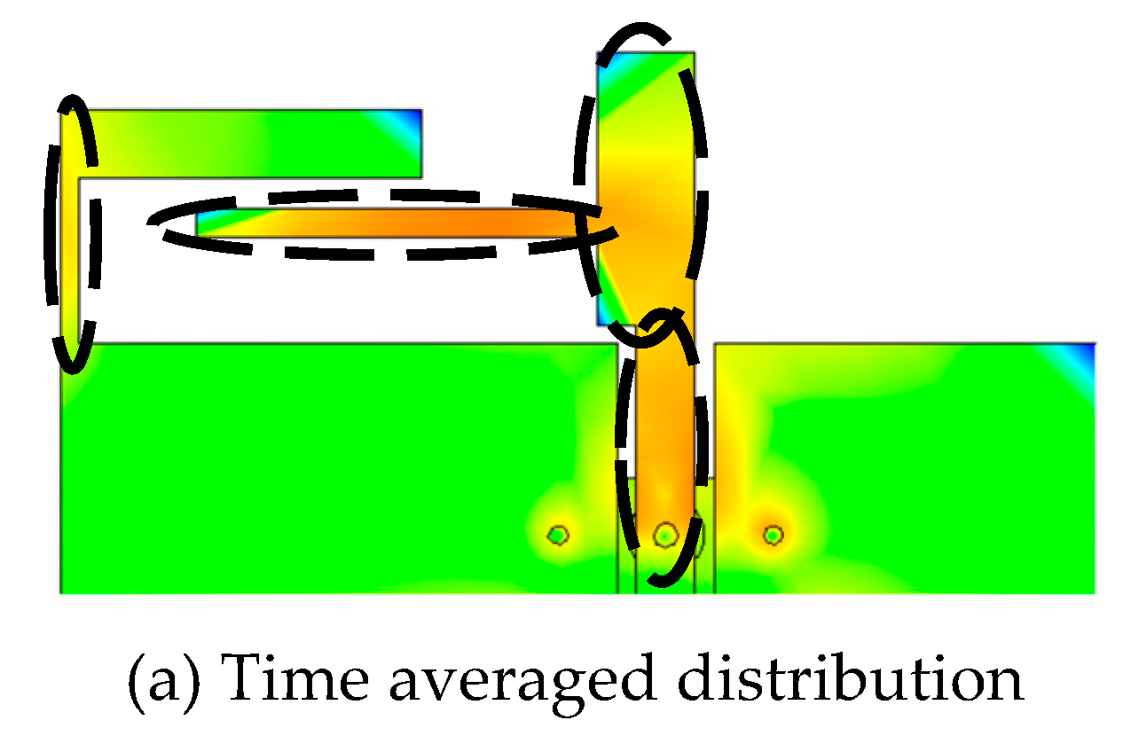
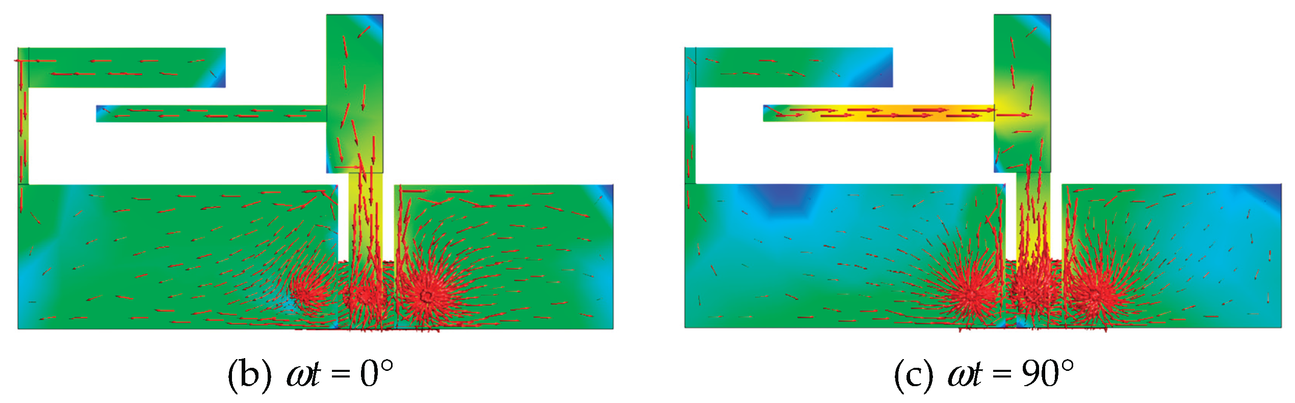
Figure 1 shows a proposed hybrid-mode antenna. The antenna consists of one T-shaped antenna and one L-shaped element. The T-shaped antenna is fed by a coplanar waveguide. The L-shaped element is loaded on the ground plane. The relative dielectric constant, the thickness, and the loss tangent of the dielectric substrate are εr = 3.6, h = 1.6 mm, and tanδ = 0.022, respectively. The antenna is excited by a coaxial feed from the back of the dielectric substrate. In both reference [15] and this study, the T-shaped element is placed at the center of the antenna. However, the L-shaped element in this study is positioned on the opposite side of the T-shaped element compared to the loop element in [15] to create a dual-band single-sense CP. Figure 2 shows that the main radiating components which contribute to the hybrid-mode. The hybrid-mode for CP in the low frequency band is produced mainly by the vertical part of the T-shaped element and the horizontal part of the L-shaped element. The hybrid-mode for CP in the high frequency band is produced mainly by the horizontal part of the T-shaped element and the vertical part of the L-shaped element. In the low frequency band, the length of the T-shaped element (the sum of solid and dashed green lines) and the length of the L-shaped element (the sum of solid and dashed blue lines) are approximately a quarter wavelength as shown in Figure 2(a). In the high frequency, the length of the T-shaped element (the sum of solid and dashed blue lines) and the length of the L-shaped element (the sum of solid and dashed green lines) are approximately a half wavelength as shown in Figure 2(b).
Since the size of the proposed antenna is small, the size of the sub-miniature A (SMA) receptacle is relatively large compared with the antenna. For side-mounting feeding, the receptacle and cable influence the measurement of the axial ratio. Therefore, the SMA receptacle is inserted from the bottom of the dielectric substrate. The positions of the center of the feed point and the shorting pins Wc and Lc are chosen so that the whole body of the SMA connector does not protrude from the ground plane [15].
Input impedances are tuned by varying the width Fs of the feed line, and the gaps ga between the feed line and the ground plane [15]. The simulations revealed the relationship between the geometric parameters and the axial ratio. As the results, the axial ratios are adjusted mainly by the length Wd and Lb of the L-shaped element and the length Lf and the position Wj of the horizontal element of the T-shaped element. The ratio of the two frequencies is adjusted due to Lb and Le. The discussion on the two frequency ratios will be conducted in Section 5. The geometric parameters of the final designed antenna for the 2.45 GHz band and the 3.5 GHz band are as follows, La=53.0, Lb=17.5, Lc=5.5, Ld=1.0, Le=5.0, Lf=20.5, LgL=28.5, LgR=19.5, Wa=28.2, Wb=3.5, Wc=3.0, Wd=8.7, We=14.2, Wf=1.5, WgL=13.0, WgR=12.5, Wj=5.6, Fs=3.0 (unit:mm) . Figure 3 shows a photograph of the fabricated antenna. The antenna was made on FR-4 substrate.
3. Antenna Characteristics
Figure 4a,b show the simulated reflection coefficient (|S11|) and the axial ratio. The good impedance matching and axial ratio are achieved in the 2.45 GHz band and the 3.5 GHz band. The simulated bandwidths of 10 dB-impedance with a 3 dB-axis ratio are 6.98% (2.35-2.52 GHz) in the low frequency band and 7.73% (3.36-3.63 GHz) in the high frequency band. The measured results are also shown for comparison. The measured results agree well with the simulated ones. The measured bandwidths are 5.30 % (2.39-2.52 GHz) in the low frequency band and 7.73 % (3.36-3.63 GHz) in the high frequency band. The simulated and measured results satisfy the design specifications of the 2.45 GHz band (2.41-2.50 GHz) and the 3.5 GHz band (3.40-3.60 GHz). In the 2.45 GHz band, the dimension of the designed antenna is 0.10 λ 2.452 (0.203 λ 2.45 0.433 λ 2.45). In the 3.5 GHz band, the dimension of the designed antenna is 0.20 λ 3.52 (0.329 λ 3.5 0.618 λ 3.5).
Figure 5a,b show the simulated radiation patterns at the frequencies that produce the minimum axial ratio. The radiation patterns are normalized by the maximum value in the xz- and yz- planes. The figure shows RHCP radiates to the +z direction and LHCP radiates to the -z direction in both frequency bands. It is confirmed that the proposed antenna radiates single-sense CP at two different frequency bands. The measured results agree reasonably well with the simulated results in the forward space of the antenna (). However, in the backward space (), there is a significant discrepancy between the measured results and simulated results. This is due to the influence of the stand used to secure the antenna.
The simulated absolute gains at 2.45 GHz and 3.5 GHz are 2.39 dBic and 0.89 dBic, respectively. The measured absolute gains at 2.45 GHz and 3.5 GHz are 1.8 dBic and 2.5 dBic, respectively.
Table 1 shows the literature on dual-band single-sense antennas, excluding reference [15]. In all literature, these represent the size of the fabricated antenna and its measurement results. Only references [1] and [4] achieve antenna sizes below 0.25 wavelength squared at both frequencies. In terms of frequency bandwidth versus size, reference [4] performs the best. However, due to the complex structure, it appears difficult to change the two frequency ratios. Since the proposed antenna has a very simple structure (just combining T-shaped and L-shaped elements), the two frequency ratios can be adjusted very easily over a wide range as shown in Section 5. Furthermore, the proposed antenna has relatively broad bandwidth at the two frequencies and is compact in size. Reference [1] has an antenna size smaller than 0.1 wavelength squared at both frequencies, but its frequency bandwidth is very small. The proposed antenna has better frequency bandwidth characteristics relative to antenna size compared to other antennas. Compared to the dual sense antenna [15] designed by the authors, the antenna in this work is slightly larger in size, but exhibits similar performance characteristics.
4. Operational Principles
In this section, operational principles of Dual-band single-sense CP and resonant modes in the frequency bands for CP are discussed.
4.1. Dual-Band Single-Sense CP
In order to investigate the effects of the L-shaped element on the reflection coefficient, axial ratio, and absolute gain, four different configurations shown in Figure 6a–d are considered. Type A is an antenna for linear polarization. Type B has an asymmetric structure with respect to the feed line. In Type C, the T- and L-shaped elements are connected to form a loop. In Type D, the L-shaped element is loaded on Type B, which is proposed antenna. Figure 7a–c show |S11|, axial ratio and absolute gain of the four types of antennas. While Type A has a peak of |S11| around 3.0 GHz, Type B has peaks at 2.1 GHz and 3.5 GHz. Furthermore, Type D has a new resonance around 2.6 GHz in addition to the resonance of Type B. It is found that the L-shaped element influences the impedance matching in both frequency bands.
The minimum axial ratio for Type B is 5.92 dB at 1.92 GHz in the low frequency band and 3.76 dB at 3.55 GHz in the high frequency band. However, when the L-shaped element is loaded on the ground (Type D), the axial ratio achieves less than 3 dB in both low and high frequency bands. When the L-shaped element is connected to the T-shaped element (Type C), the minimum axial ratio is less than 1dB in the low frequency band, similar to the proposed antenna. However, the minimum peak of the axial ratio does not appear in the high frequency band. To radiate circular polarization at two frequencies, it is important not to connect the L-shaped element and the T-shaped element to form a loop.
From Figure 7(c), it can be confirmed that Type B radiates LHCP in the low frequency band and RHCP in the high frequency band. However, the proposed antenna radiates RHCP in both frequency bands. It can be seen that the radiated field in the low frequency band is reversed by the L-shaped element. Thus, the L-shaped element contributes significantly to the radiation characteristics (sense of circularly polarized wave, axial ratio and gain).
Table 2 shows the magnitude and the phase of Eθ and Eφ at θ=0° in the xz plane at the frequency giving the minimum axial ratio in the low frequency band of Type B and Type D. In Type B, |Eθ| is 4.66 dB larger than |Eφ|. In Type D, however, the difference between |Eθ| and |Eφ| is very small (0.35 dB). The both |Eθ| and |Eφ| of Type D are increasing from those of Type B. The phases of Eθ and Eφ in Type B are 118° and -175°, and those in Type D are -85° and -173°. The phase of Eφ in Type B changes little in that of Eφ when the L-shaped element is loaded, but the phase of Eθ changes significantly.
Table 3 shows the magnitude and the phase of Eθ and Eφ at θ=0° in the xz plane for Type B and Type D in the high-frequency band. |Eφ| of Type D is also higher than that of Type B. However, the increase is smaller than that in the low frequency band. |Eθ| is almost unchanged between Types B and D. The phase change is very small for both Eφ and Eθ. These suggest that the horizontal element of the L-shaped element does not have much effect on the Eq in the high frequency band. The axial ratio is adjusted by a slight increase in |Eφ|.
Figure 8a shows the time average of the electric current distribution at the minimum axial ratio at 2.45GHz in the low frequency band. This frequency is the same as the calculation frequency of Table 2. The electric currents with large magnitude occur in the T-shaped element and in the L-shaped element. Based on Figure 8(b), when ωt = 0°, the x component of the electric current (Jx) flows in the same direction on the horizontal elements of both the L-shaped element and the T-shaped element. Additionally, the y component of the electric current (Jy) also flows in the same direction on the vertical elements of both T- and L- shaped elements. When ωt = 90°, however, Jx on the L-shaped element flows in the opposite direction to Jx on the T-shaped element, and its intensity is great. For this reason, the phase of Eθ differs by around 180° between Type B and Type D (Table 2), resulting in opposite rotation directions shown in Figure 7. |Eφ| increases with radiation due to Jy on the L-shaped element.
In the high frequency band, the directions of Jx on the T-shaped element and L-shaped element are the same for both ωt = 0° and 90°. Similarly, Jy is also the same. Therefore, the phase change of the electric fields between Type B and Type D is small. Although Type B doesn’t radiate CP, it is close to 3dB. As shown in Table 3, in Type B, |Eφ| is smaller compared to |Eθ|, but by adding the L-shaped element, |Eφ| is generated by Jy on the L-shaped element, achieving improved axial ratio.
Figure 8.
Electric current distributions at 2.45 GHz.
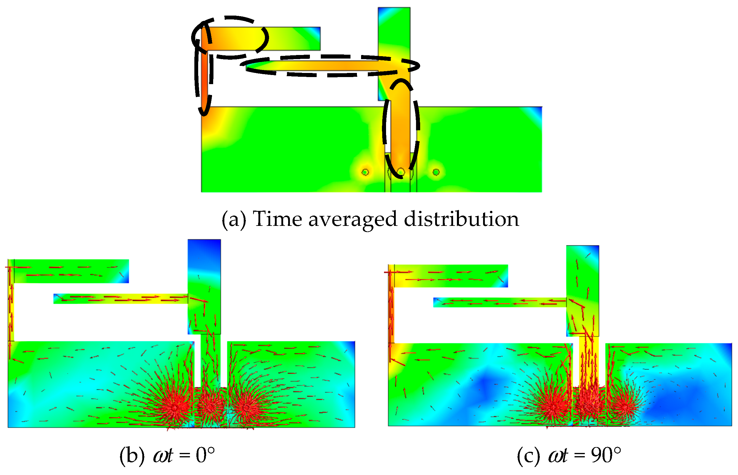
Figure 9.
Electric current distributions at 3.5 GHz.
4.2. Resonant Mode of Dual Band
In the previous subsection, the principle of generating dual-band single-sense circularly polarized wave was explained using the magnitude and phase of the two radiated electric field components Eθ and Eφ. In this subsection, the relationship between the geometric parameters and resonant modes is discussed through characteristic mode analysis (CMA).
Figure 10 shows the Mode Significance (MS) in CMA. Table 4 shows the Characteristic Angle (CA). The upper row of the column shows the CA value, while the lower row indicates the difference from 180°. At 2.45 GHz, Mode 1 and Mode 2 are dominant. At 2.45 GHz, the CA of Mode 1 and Mode 2 are 142.54° (=180°-37.46°) and 234.37° (=180°+54.37°) respectively, and they deviate from 180° by almost the same amount. Also, the phase difference between these two modes is approximately 90°. This means that Mode 1 and Mode 2 are orthogonal. The MS value for Mode 1 is 0.98 at 2.2 GHz, and the MS value for Mode 2 is 0.91 at 2.6 GHz, which causes |S11| peaks around 2.2 GHz and 2.6 GHz as shown in Figure 7(a). At 2.45 GHz, the MS values of these two orthogonal modes (Mode 1 and Mode 2) are close, so these two orthogonal modes contribute to the radiation of a circularly polarized wave. Figure 11 shows the electric current distribution at 2.45 GHz of Mode 1 and Mode 2. The lengths L1 in Mode 1 and L2 in Mode 2 shown in black, which indicate strong current intensity, are approximately 28.5 mm (0.23 λ 2.45) and 29.5 mm (0.24 λ2.45), and the antenna operates as a quarter-wavelength antenna.
From Figure 10, at 3.47 GHz, Mode 2 has the largest MS value=0.94. This is followed by Mode 4 (MS=0.35) and Mode 1 (MS=0.31), which have nearly identical values. Additionally, the CA value of Mode 2 is 167.32° (Table 4), which is close to 180°. This means that Mode 2 is the resonant mode. Figure 12 shows the electric current distribution at 3.47 GHz of Mode 2 and Mode 4. Since the electric current distribution of Mode 1 is similar to that of Mode 2, it has been omitted in this paper. At 3.47 GHz, a strong electric current of Mode 2 occurs in the T-shaped element, and a slight electric current of Mode 4 occurs in the L-shaped element. The addition of the L-shaped element generates Mode 4. Although the MS value of Mode 4 is low, the electric current in the vertical element contributes to the radiation of circular polarization as shown in the previous subsection. The length L3 in Mode 2 shown in black, which indicate strong current intensity, is approximately 35 mm (0.41 λ 3.47). This means the proposed antenna operates as a half-wavelength antenna.
5. Parametric Studies
For dual-band antennas, control of the ratio between the two frequencies is important. In particular, geometric parameters that allow tuning of only one frequency while keeping the other frequency fixed are crucial in antenna design. Based on the discussion in Section 4, it was found that the horizontal element of the L-shaped element contributes significantly to the low frequency band, while the T-shaped element contributes significantly to the high frequency band. In this section, among the various geometric parameters, simulated results are presented for geometric parameters that can control only the low frequency band and geometric parameters that can control only the high frequency band.
Figure 13(a) and (b) show the reflection coefficient and axial ratio when the length Lb of the horizontal element of the L-shaped element is varied. When Lb is shortened, the change in frequency at which the minimum axial ratio occurs in the high frequency band is very small, but the frequency at which the minimum axial ratio occurs at low frequencies increases. Additionally, the impedance matching remains unchanged in the high frequency band, and in the low frequency band, it almost overlaps with the frequency band where the axial ratio is below 3 dB.
Figure 14a,b show the reflection coefficient and axial ratio when the width Le of the vertical element of the T-shaped element is varied. When Le is increased, there is no change in the frequency at which the minimum axial ratio occurs in the low-frequency band, but the frequency at which the minimum axial ratio occurs at high frequencies decreases. Additionally, the impedance matching remains unchanged in the low frequency band, and in the high frequency band, it almost overlaps with the frequency band where the axial ratio is below 3 dB.
For circularly polarized antennas, the frequency band where the axial ratio is below 3 dB and the reflection coefficient is below -10 dB is important. Therefore, Figure 15 and Figure 16 show the center frequencies, the ratio of the two center frequencies, and the frequency bandwidth where the axial ratio is below 3 dB and the reflection coefficient is below -10 dB when Lb and Le are varied.
It is found that the center frequency in the low frequency band can be largely controlled by Lb, while the center frequency in the high frequency band can be largely controlled by Le. Within the range of Lb and Le shown in the Figure 15 and Figure 16, good impedance matching is achieved, the frequency bandwidth is also more than 4 %. Additionally, fH/fL achieves dual-band single-sense CP in a wide range from 1.15 to 1.45. The value of fH/fL lower than 1.2 has not been achieved in the references in Table 1, making the proposed antenna very effective compared to other references in terms of the variable range of fH/fL.
As shown above, the two frequency ratios can be reduced by Lb and Le, and it is also possible to combine the two frequency bands into one by adjusting the combination of Lb and Le. Figure 17 shows the simulated results at Lb = Le =8 mm. By merging the two frequency bands into one, the frequency bandwidth with a 10dB-impedance with a 3 dB-axial ratio is 17.4 % (2.76 GHz-3.29 GHz). The design of a wideband circularly polarized antenna is also possible.
6. Conclusions
A compact printed hybrid-mode antenna for dual-band single-sense CP was proposed. The proposed antenna consists of a T-shaped element and an L-shaped element. The T-shaped element is connected to the feeding line and the L-shaped element is connected to the ground. The geometry of the antenna is very simple and the size of the antenna is compact. By simulation, the hybrid-mode for dual-band single-sense CP is elucidated. The proposed antenna has good circularly polarized performance. Using CMA, the relationship between antenna components and resonance has been clarified. As a result, it is shown that the antenna operates as a quarter-wavelength antenna in the low-frequency band and as a half-wavelength antenna in the high-frequency band. Through a parametric study, the ratio between the center frequencies of the high and low frequency bands of the proposed antenna can be widely adjusted, enabling antenna design even in the low ratio region where design was not possible in other literature.
The simulated reflection coefficient, axial ratio, radiation pattern, and absolute gain are compared with the measurement results, and both show good agreement. These results validate the present study.
MIMO system is used in sub6GHz 5G. The proposed antenna is effective as an antenna element for sub6 GHz 5G MIMO system.
References
- Bao, X. L.; Ammann, M. J. Dual-frequency circularly-polarized patch antenna with compact size and small frequency ratio. IEEE Trans. Antenn. Propag. 2007, 55, 2104-2107. [CrossRef]
- Nasimuddin; Chen, Z. N.; Qing , X. Dual-band circularly-polarized S-shaped slotted patch antenna with a small frequency-ratio. IEEE Trans. Antenn. Propag. 2010, 58, 2112-2115. [CrossRef]
- Sung , Y. Dual-band circularly-polarized pentagonal slot antenna. IEEE Antenn. Wireless Propag. Lett. 2011, 10, pp. 259-261. [CrossRef]
- Chen, C.-H.; Yng, E. K. N. Dual-band circularly-polarized CPW-fed slot antenna with a small frequency ratio and wide bandwidths. IEEE Trans. Antenn. Propag. 2011, 59, 1379-1384.
- Xu, Y.; Zhu, L.; Liu, N.-W. Design approach for a dual-band circularly polarized slot antenna with flexible frequency radio and similar in-band gain. IEEE Antenn. Wireless Propag. Lett. 2022, 21, 1037-1041. [CrossRef]
- Kandasamy, K.; Majumder, B.; Mukherjee, J.; Ray, K. P. Dual-band circularly polarized split ring resonators loaded square slot antenna. IEEE Trans. Antenn. Propag. 2016, 64, 3640-3645. [CrossRef]
- Liang, W.; Jiao, Y.-C.; Luan, Y.; Tian, C. A dual-band circularly polarized complementary antenna. IEEE Antenn. Wireless Propag. Lett. 2015, 14, 1153-1156. [CrossRef]
- Tan, M. -T.; Wang, B.-Z. A dual-band circularly polarized planar monopole antenna for WLAN/Wi-Fi Applications. IEEE Antenn. Wireless Propag. Lett. 2016, 15, 670-673.
- Saini, R. K.; Dwari, S.; Mandal, M. K. CPW-fed dual-band dual-sense circularly polarized monopole antenna. IEEE Antenn. Wireless Propag. Lett. 2017, 16, 2497-2500. [CrossRef]
- Chen, C.; Yung, E. K. N. Dual-band dual sense circularly-polarized CPW-fed slot antenna with two spiral slots loaded. IEEE Trans. Antenn. Propag. 2009, 57, 1829-1833. [CrossRef]
- Chen, Y.-Y.; Jiao, Y.-C.; Zhao, G.; Zhang, F.; Liao, Z. L.; Tian, Y. Dual-band dual-sense circularly polarized slot antenna with a C-shaped grounded strip. IEEE Antenn. Wireless Propag. Lett. 2011, 10, 915-918. [CrossRef]
- Bao, X.; Ammann, M. J. Dual-frequency dual-sense circularly-polarized slot antenna fed by microstrip line. IEEE Trans. Antenn. Propag. 2008, 56, 645-649. [CrossRef]
- Bao, X. L.; Ammann, M. J. Monofilar spiral slot antenna for dual-frequency dual-sense circularly-polarization. IEEE Trans. Antenn. Propag. 2011, 59, 3061-3065. [CrossRef]
- Xu, R.; Li, J.-Y.; Liu, J.; Zhou, S.-G.; Wei, K.; Xing, Z.-J. A simple design of compact dual-wideband square slot antenna with dual-sense circularly polarized radiation for WLAN/Wi-Fi communications. IEEE Trans. Antenn. Propag. 2018, 66, 4884-4889. [CrossRef]
- Fujimoto, T.; Guan, C.-E. A compact printed hybrid-mode antenna for dual-band deal-sense circular polarization. IET Microwaves, Antennas & Propag. 2023, 17, 777-785.
Figure 1.
Geometry of the proposed antenna.
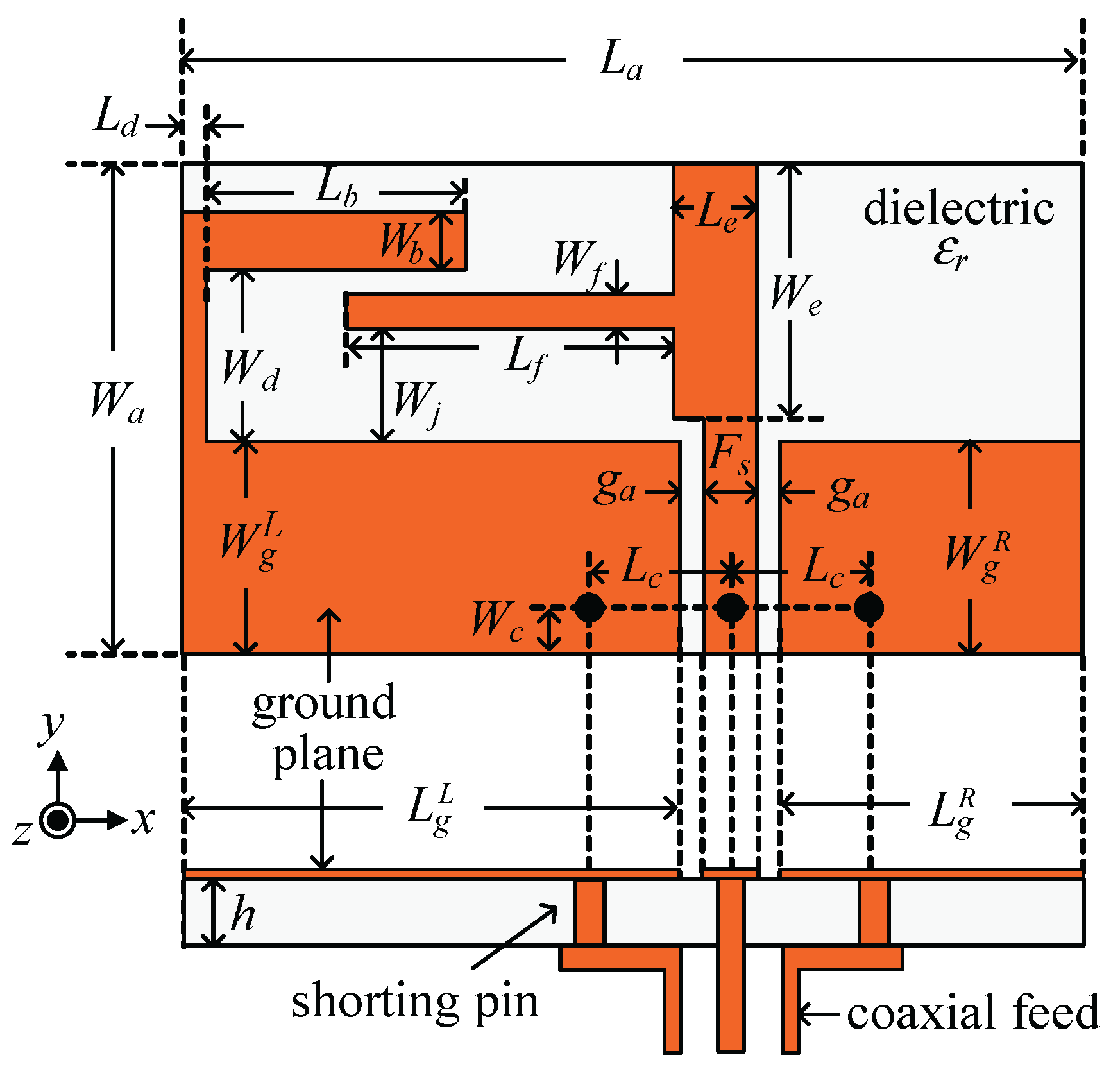
Figure 2.
Single-sense circular polarization (CP) produced by hybrid-mode.
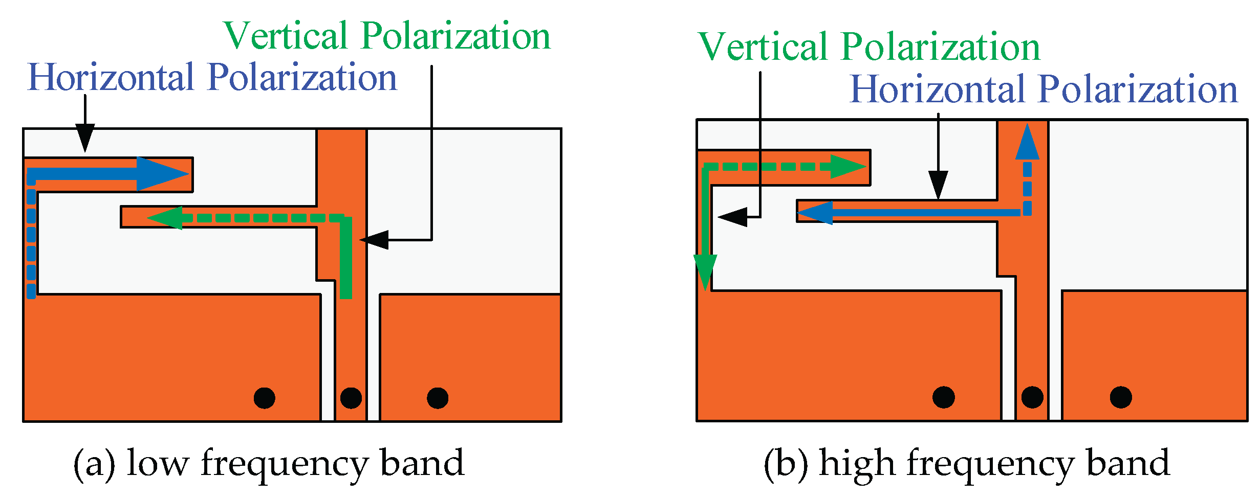
Figure 3.
Fabricated antenna.
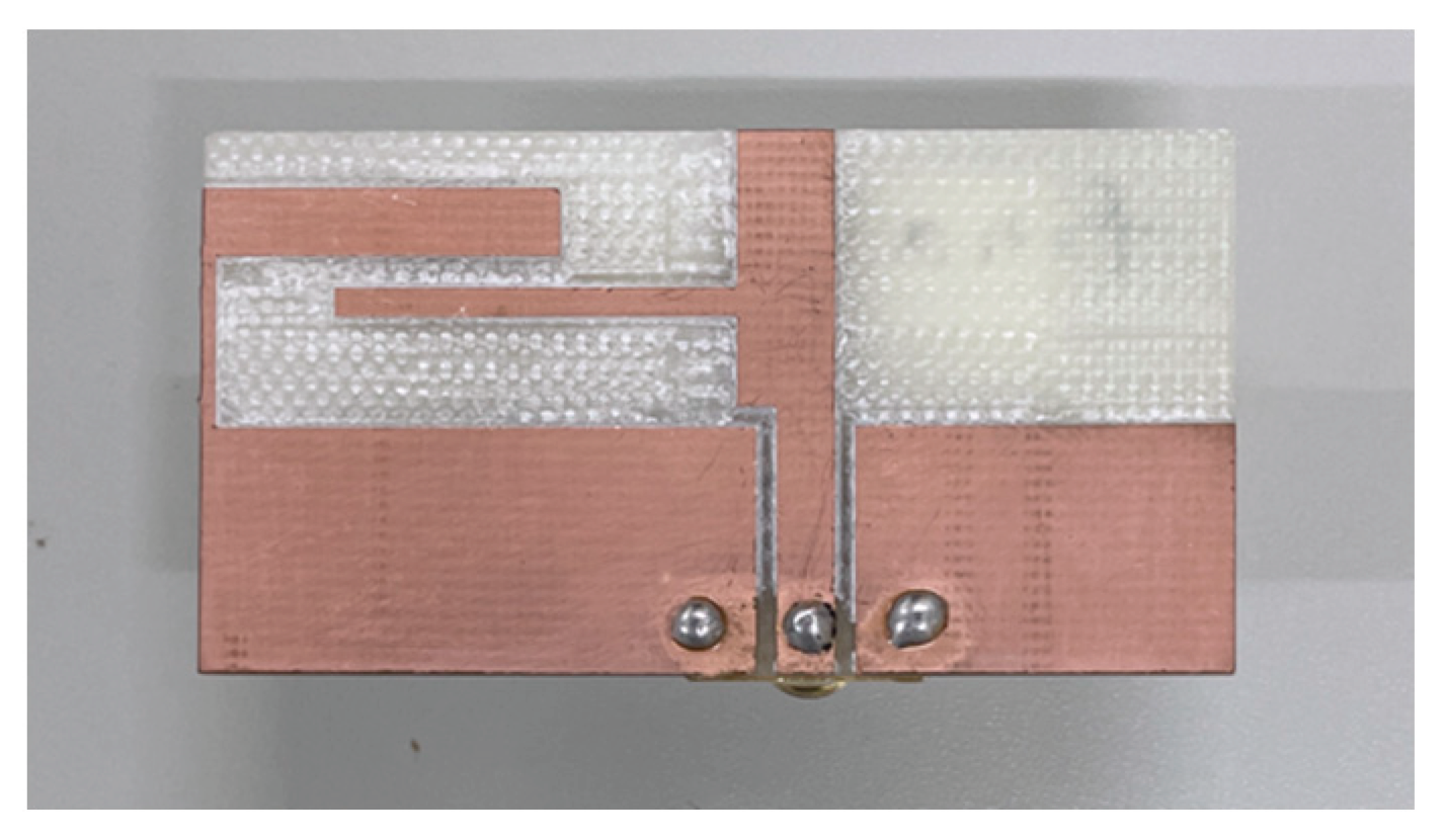
Figure 4.
Comparison of simulated and measured results (reflection coefficient and axial ratio).
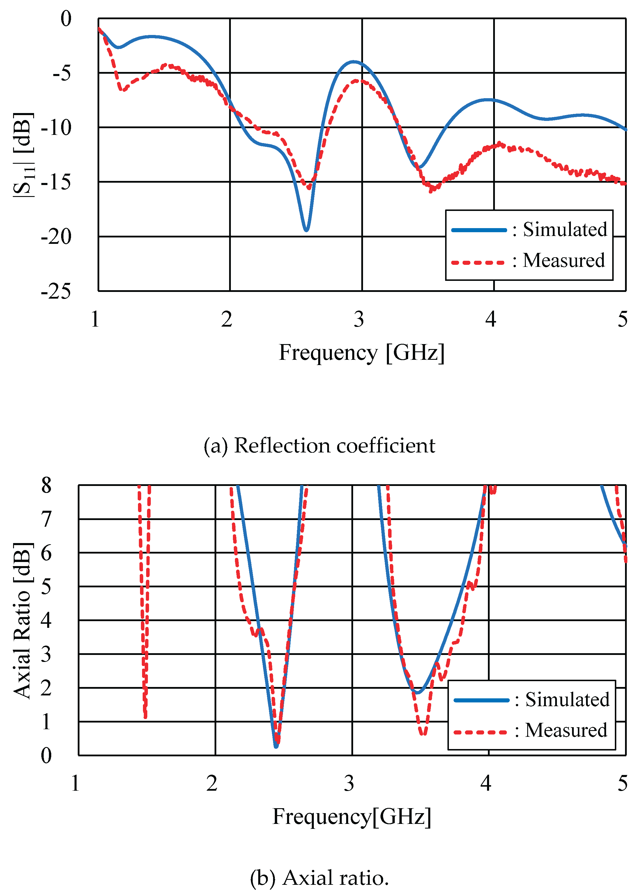
Figure 5.
Comparison of simulated and measured radiation patterns.
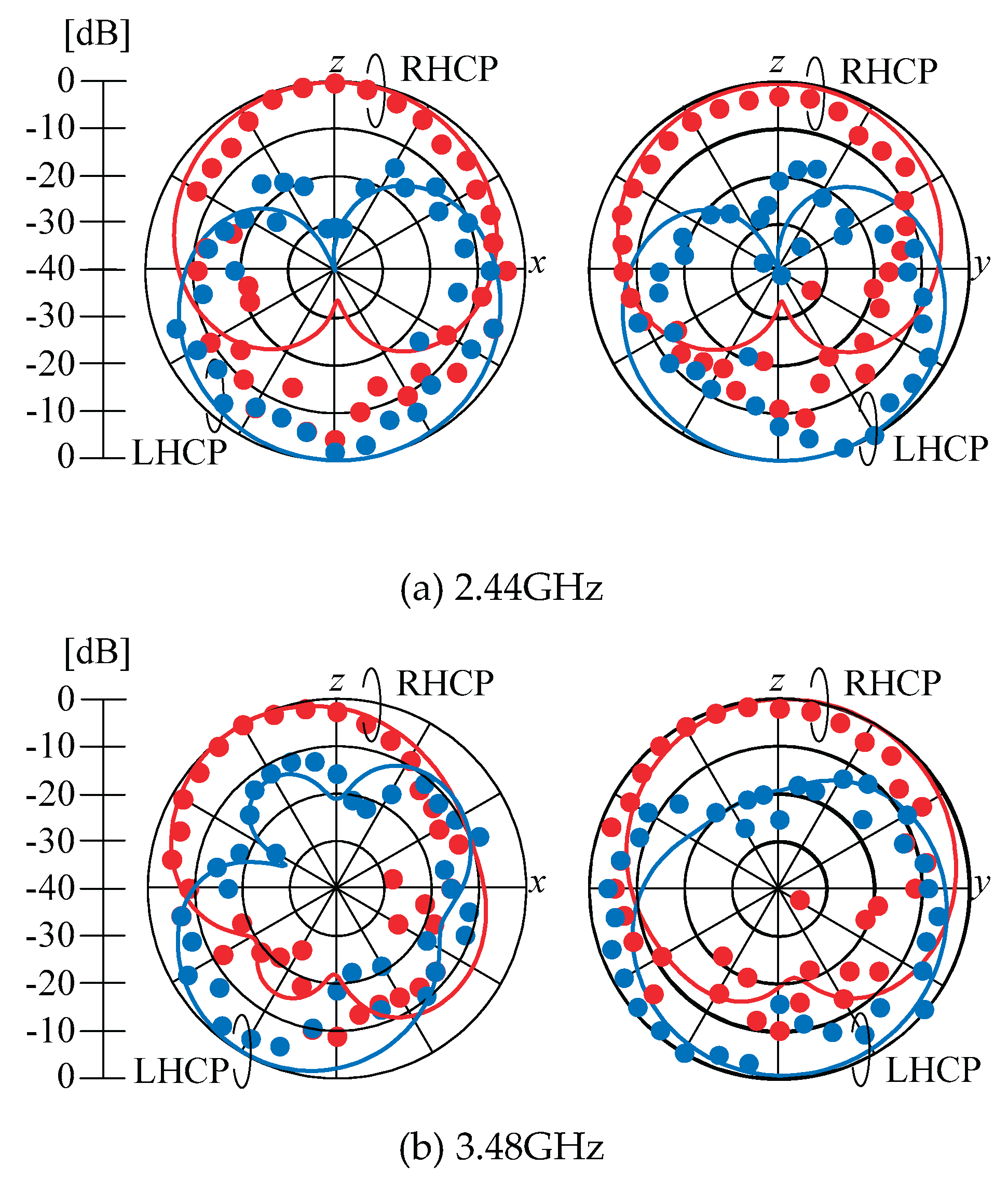
Figure 6.
Four types of antennas.
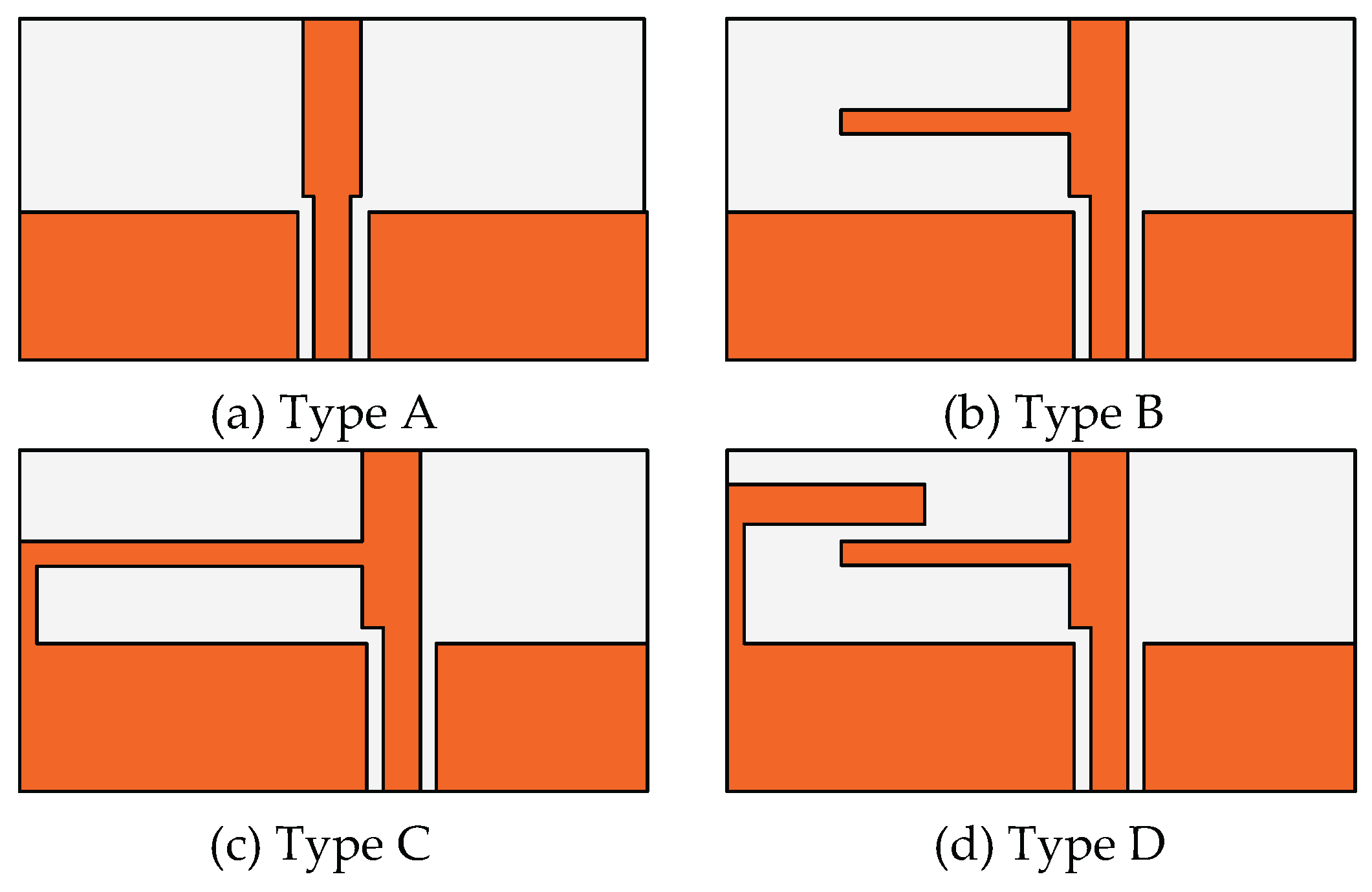
Figure 7.
Comparison of four antennas' characteristics.

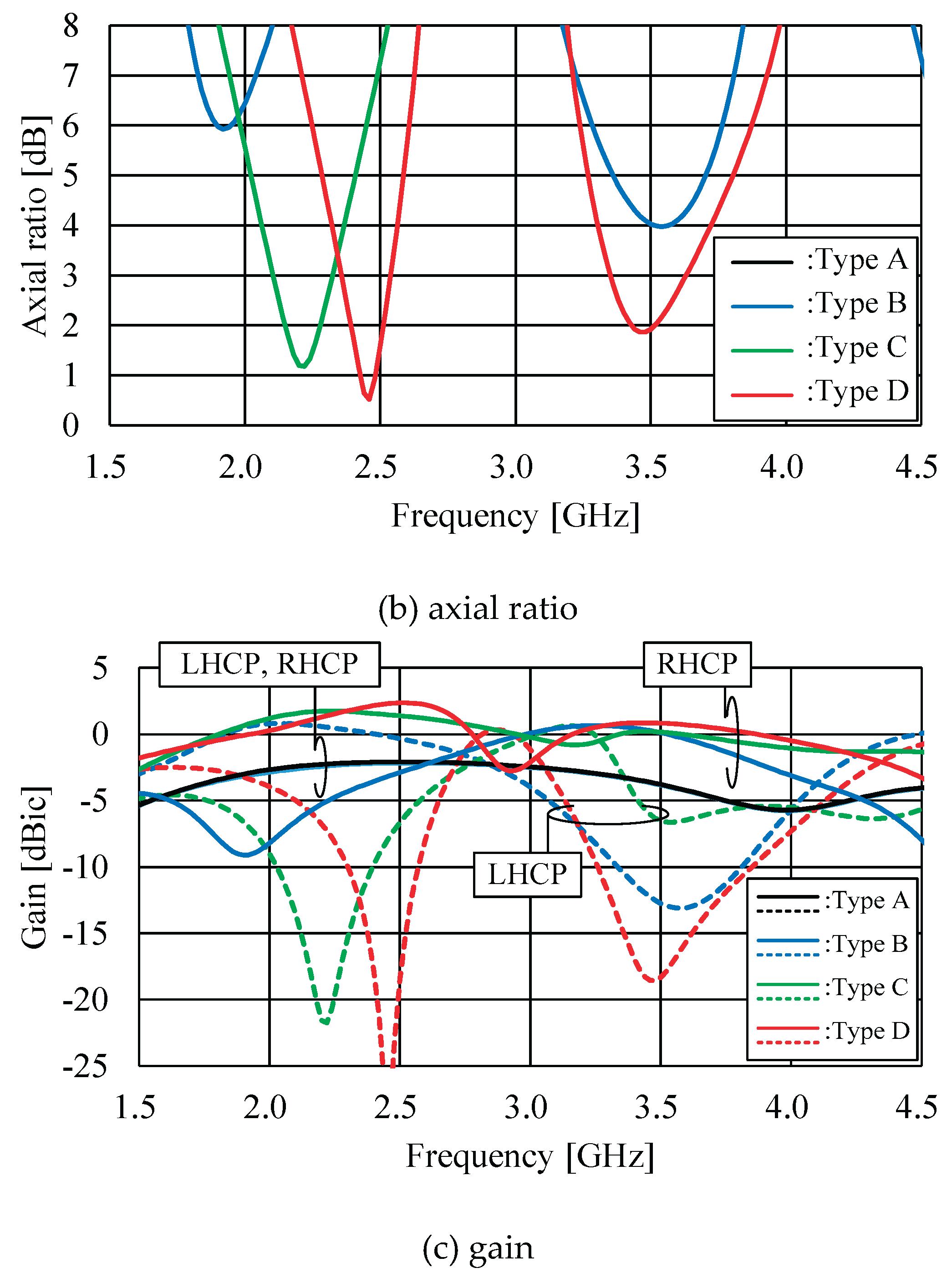
Figure 10.
Mode Significance.
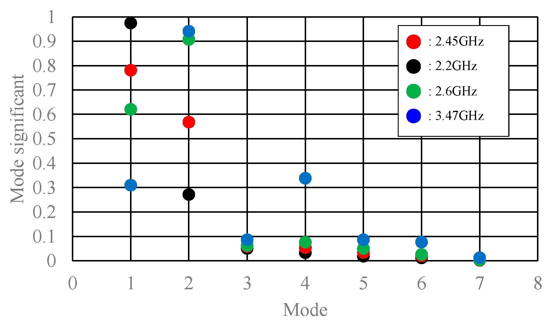
Figure 11.
Electric current distributions 2.45 GHz.
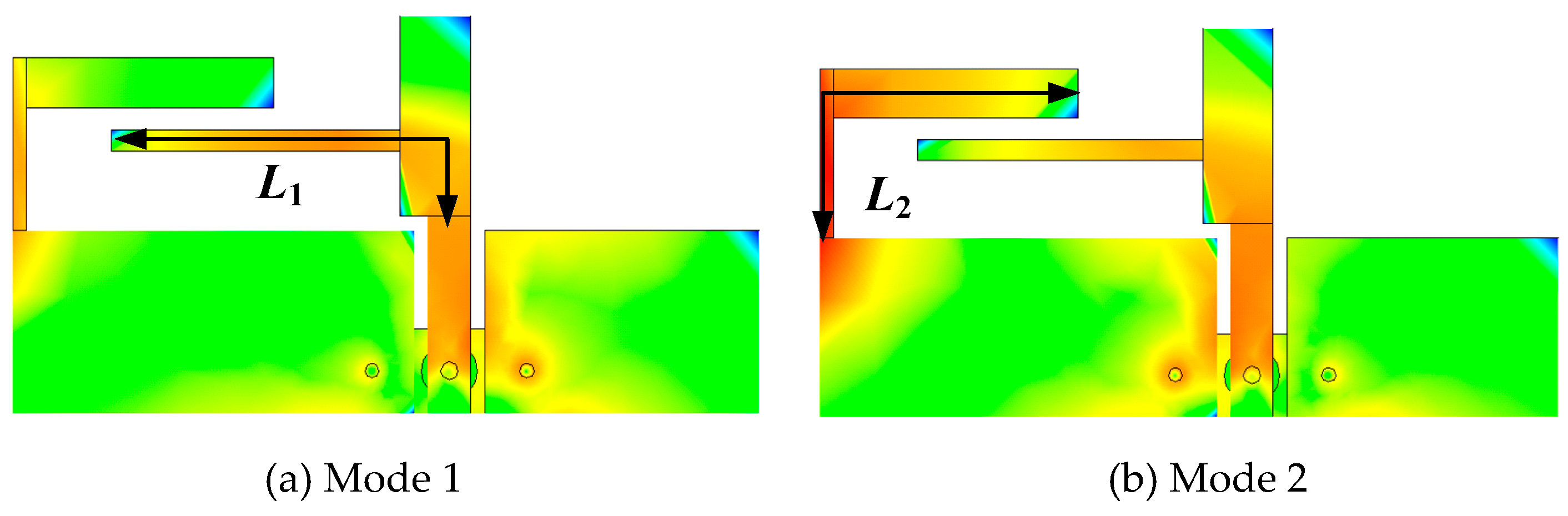
Figure 12.
Electric current distributions 3.47 GHz.
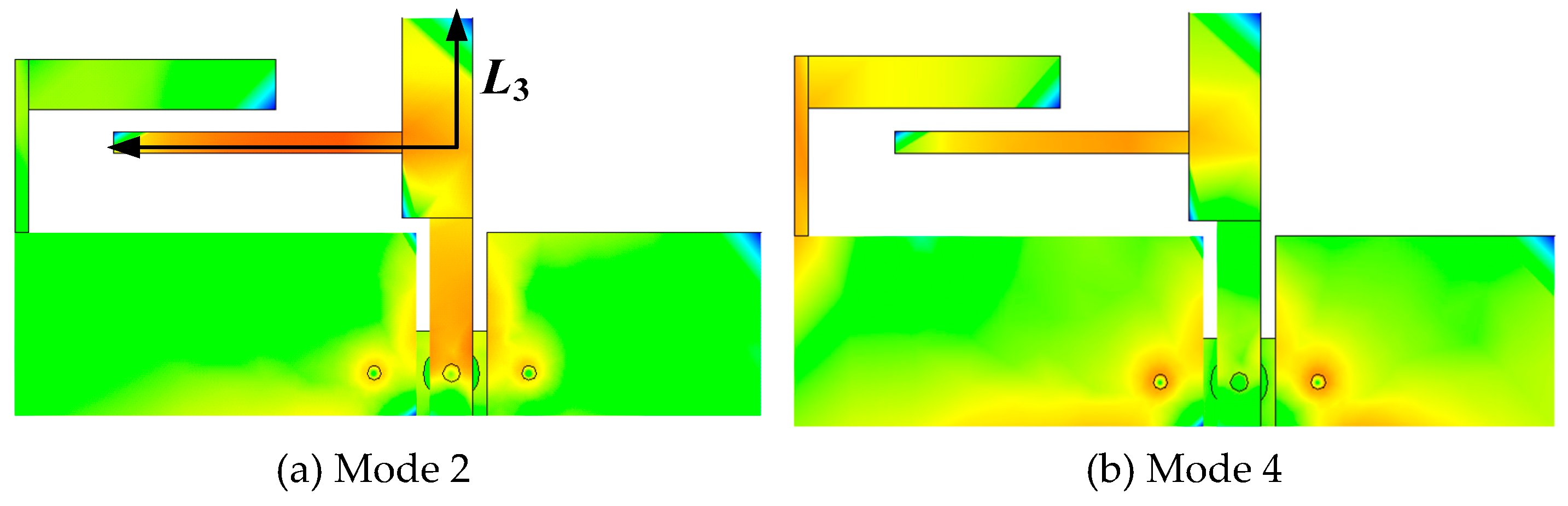
Figure 13.
For changing of Lb (Le=5mm).
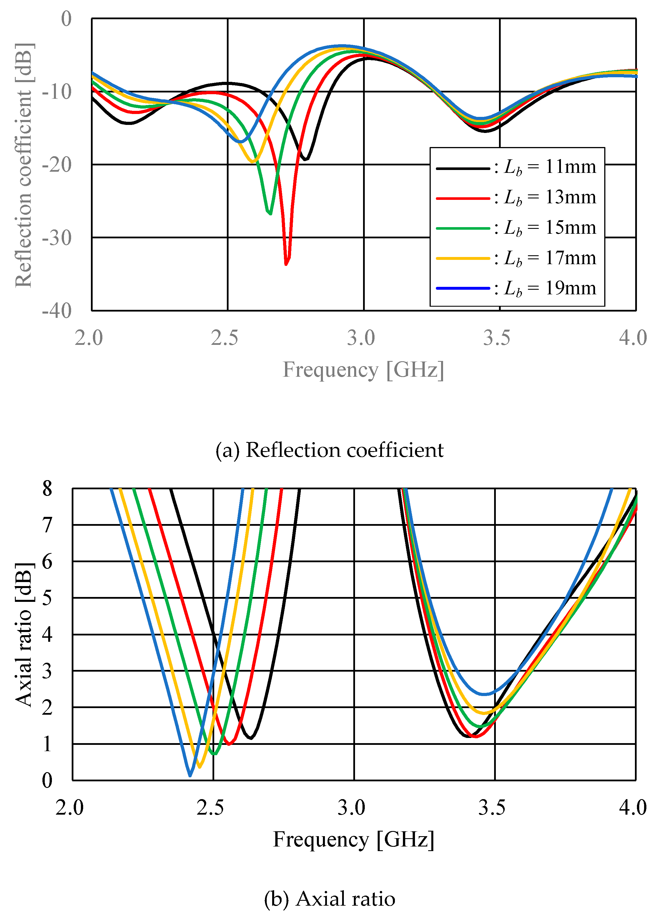
Figure 14.
For changing of Le (Lb=17.5mm).
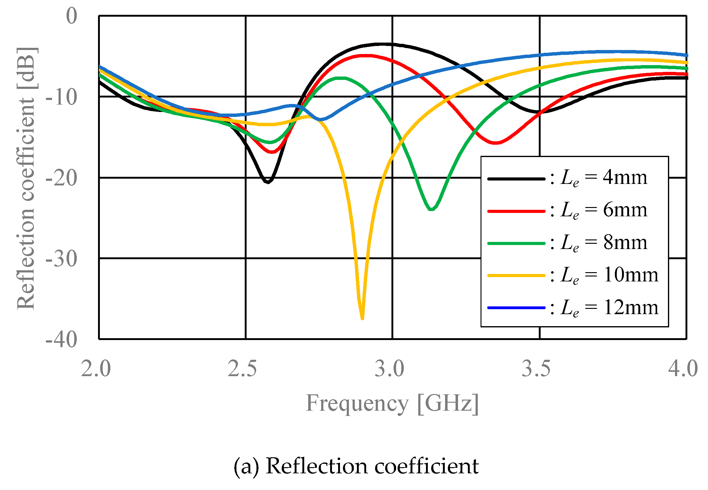
Figure 15.
For changing of Lb (Le=5mm).
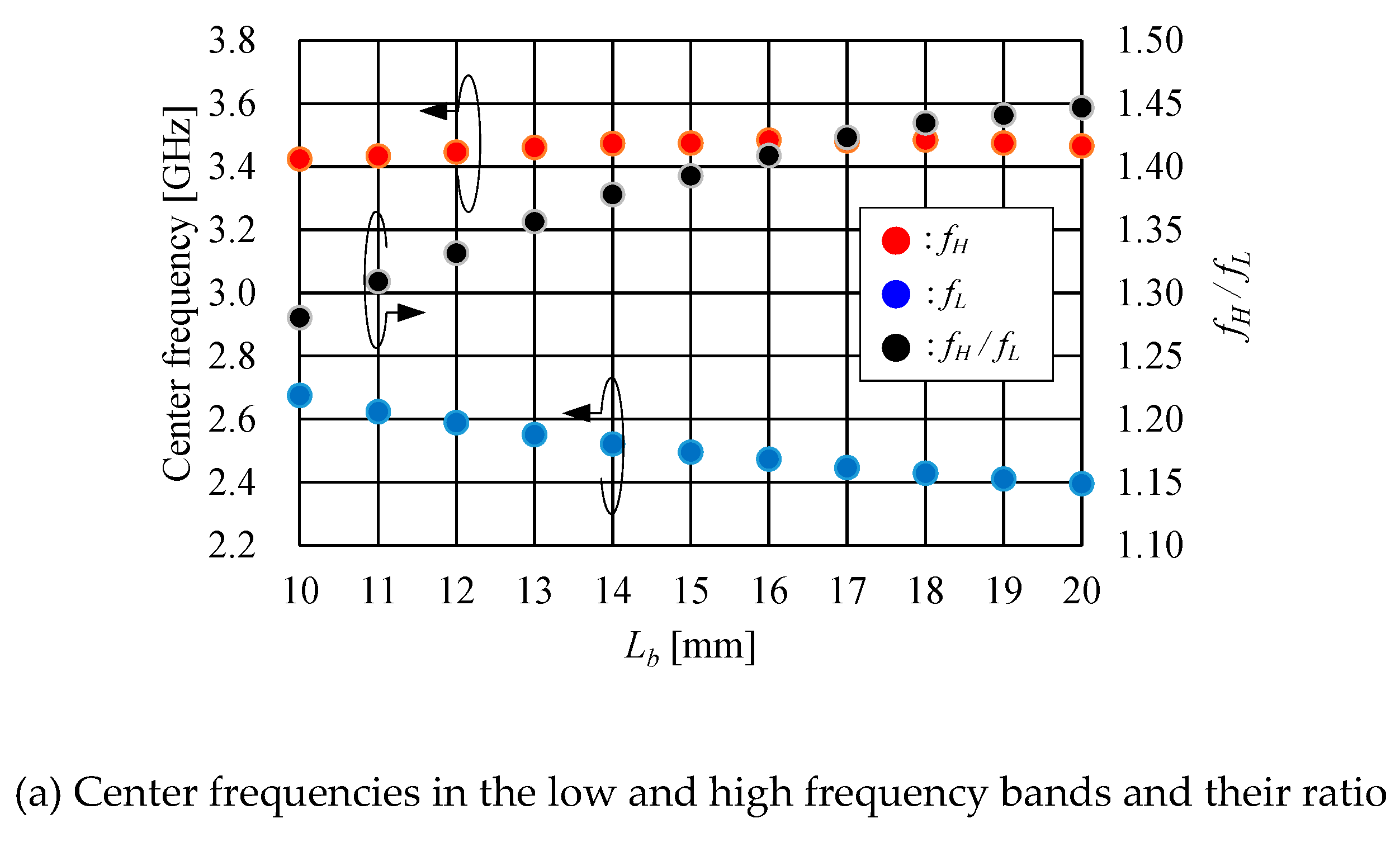
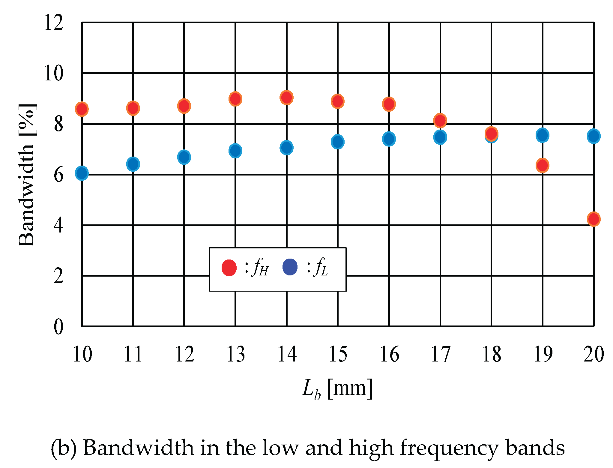
Figure 16.
For changing of Le (Lb=17.5mm).
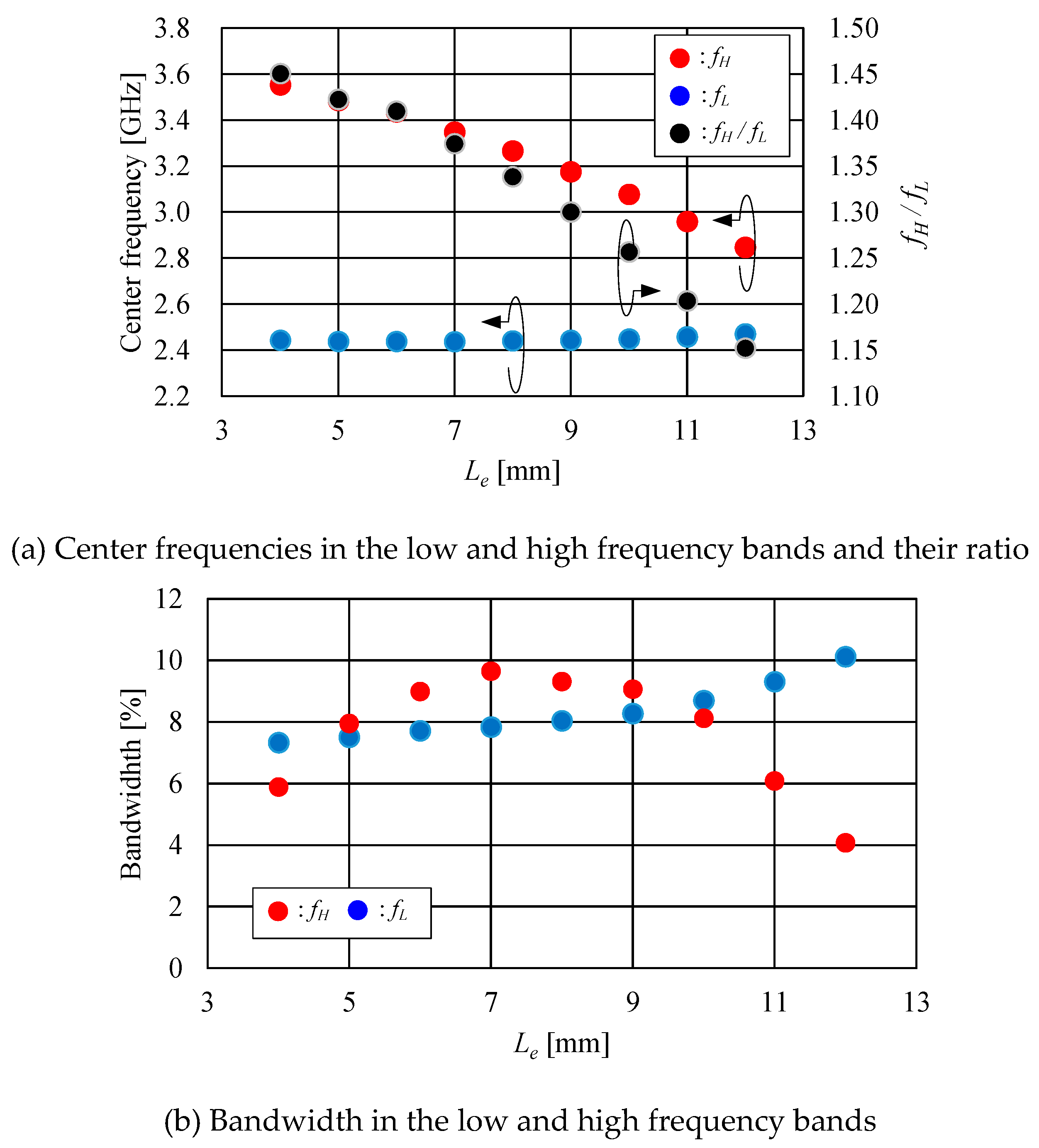
Figure 17.
Simulated reflection coefficient and axial ratio at Lb= Le=8mm.
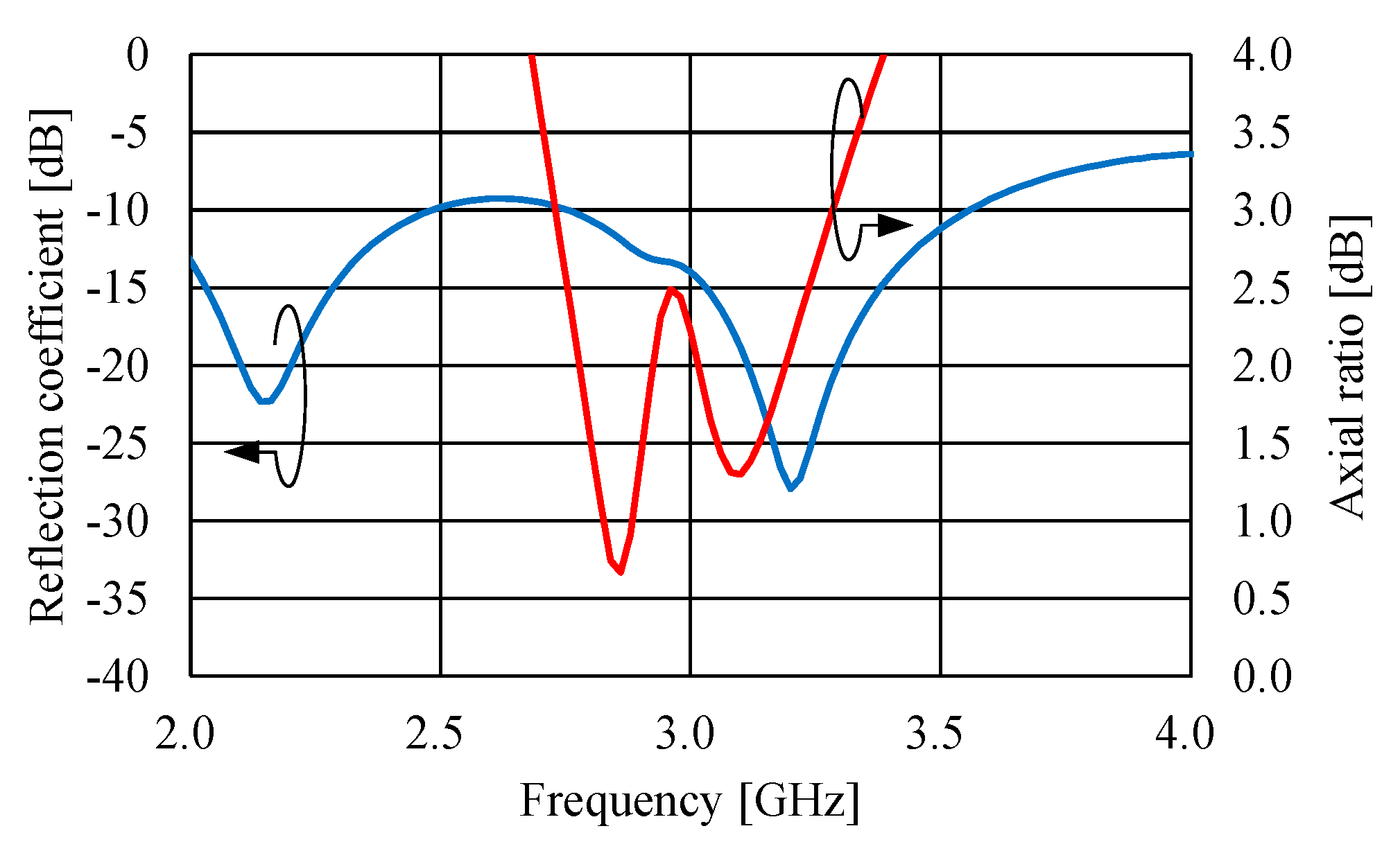

Table 1.
Comparison of the bandwidth, the antenna size and the frequency ratio of our work and other previous in the literature.
Table 1.
Comparison of the bandwidth, the antenna size and the frequency ratio of our work and other previous in the literature.
| BW [%] |
BW [%] |
Size [λL2] |
Size [λH2] |
fH/fL | single /dual (sense) |
|
| [1] | 0.98 | 1.08 | 0.06 | 0.087 | 1.21 | single |
| [2] | 6.87 | 0.57 | 0.221 | 0.365 | 1.27 | single |
| [3] | 7.13 | 3.25 | 1.440 | 8.649 | 2.45 | single |
| [4] | 9.09 | 11.11 | 0.129 | 0.213 | 1.29 | single |
| [5] | 2.84 | 2.10 | 0.754 | 2.599 | 1.86 | single |
| [5] | 3.88 | 1.38 | 0.805 | 1.309 | 1.28 | single |
| [6] | 3.23 | 4.21 | 0.523 | 1.228 | 1.53 | single |
| [15] | 7.32 | 9.04 | 0.0741 | 0.151 | 1.44 | dual |
| This work | 5.30 | 7.73 | 0.100 | 0.203 | 1.42 | single |
Table 2.
Eθ and Eφ in the low frequency band.
| Min. AR [dB] |
Freq. [GHz] |
[dB] |
[°] |
|
| Type B | 5.92 | 1.92 | 4.66 (-7.64, -12.3) |
-67 (118.0, -175.0) |
| Proposed (Type D) |
0.44 | 2.45 | 0.35 (-2.77, -3.12) |
87.7 (-85.3, -173.0) |
Table 3.
Eθ and Eφ in the high frequency band.
| Min. AR [dB] |
Freq. [GHz] |
[dB] |
[°] |
|
| Type B | 3.97 | 3.54 | 3.05 (-3.63, -6.68) |
77.0 (178.0, 101.0) |
| Proposed (Type D) |
1.85 | 3.47 | 1.11 (-3.22, -4.33) |
78.5 (177.0, 98.50) |
Table 4.
Characteristics angle (CA).
| Mode 1 | Mode 2 | Mode 3 | Mode 4 | |
| 2.45GHz | 142.54° -37.46° |
234.37° 54.37° |
93.32° -86.68° |
266.93° 86.93° |
| 3.47GHz | 108.21° -71.79° |
167.32° -12.68° |
94.92° -85.08° |
250.15° 70.15° |
Disclaimer/Publisher’s Note: The statements, opinions and data contained in all publications are solely those of the individual author(s) and contributor(s) and not of MDPI and/or the editor(s). MDPI and/or the editor(s) disclaim responsibility for any injury to people or property resulting from any ideas, methods, instructions or products referred to in the content. |
© 2025 by the authors. Licensee MDPI, Basel, Switzerland. This article is an open access article distributed under the terms and conditions of the Creative Commons Attribution (CC BY) license (http://creativecommons.org/licenses/by/4.0/).
Copyright: This open access article is published under a Creative Commons CC BY 4.0 license, which permit the free download, distribution, and reuse, provided that the author and preprint are cited in any reuse.


