
Submitted:
13 November 2024
Posted:
14 November 2024
You are already at the latest version
Abstract
In this paper, we present an array-fed Fabry–Perot cavity antenna (FPCA) based on a partially reflecting sheet (PRS) capable of generating a circularly polarized (CP), highly directive, far-field radiation pattern in the 27–28.5 GHz frequency range. The PRS, the cavity, and the array of feeders serve to different purposes in this original structure. The PRS is engineered to produce a circular polarization from a linearly polarized source placed inside the cavity. The cavity is optimized to obtain a directive conical beam from the dipole-like pattern of the simple source, and allows for a frequency scan of the beam along the elevation plane. The array of feeders is designed to obtain a pencil beam whose azimuthal pointing direction can be controlled by properly phasing the sources. The radiation performance is studied with a specific application of the reciprocity theorem in a full-wave solver along with the pattern multiplication principle. A number of configurations are investigated and presented to show the potential of the proposed solution in terms of design flexibility and radiation performance.
Keywords:
Fabry–Perot cavity antennas
; circular polarization
; phased arrays
; leaky-wave antennas
1. Introduction
Several applications areas, such as remote sensing, satellite communications, radar, and health engineering call for antenna solutions capable of realizing circularly polarized (CP) beams. No need of reciprocal alignment, improved resistance to multipath fading, and capability to easily overcome obstacles on the data link, confer to CP regime an increased appeal. With respect to other modern techniques, based on metasurfaces in transmitting or reflecting mode (see, e.g., [1,2,3,4]), CP leaky-wave antennas (LWAs), using a single-element structure, offer interesting advantages in terms of compactness, planar geometries, and simple feeding schemes, critical for antennas in integrated complex systems.
LWAs are a class of traveling-wave radiators based on open waveguides. The leaky-wave theory is exploited to design both one-dimensional (1-D) and two-dimensional (2-D) antennas. While for the first category a fundamental direction is set, a radial symmetry of power flow is characteristic for the second one. For both categories, on the elevation plane, the frequency dispersion of the complex propagation wavenumber is exploited to promptly reconfigure both the pointing angle and the directivity of the far-field beam. This latter condition naturally simplifies the feeding network which may consist in simple, non-directive, dipole-like linearly polarized sources [5,6,7,8,9,10,11,12,13,14,15]. Typical for a vast majority of LWAs, planar geometries and interfaces, can be suitably modified by further deposing metallic, dielectric or metallic-dielectric electrically thin layers, commonly recreating periodic patterns. Due to their ability to manipulate the interacting electromagnetic field, it is common to refer to such structures as to . Depending on the specific application and desired features within the framework of leaky-wave antennas, the latter can be operated in homogenization regime, with the periodicity of the lattice being a small fraction of the operating wavelength and beyond, where the two dimensions become comparable and space harmonics appear [8].
Substrate integrated waveguides (SIWs) represent a well-established technology for 1-D LWAs [16,17]. In [18] a scanning CP fan beam is obtained from a SIW based on a T-shaped inter-digital slot unit cell and fed by a simple coaxial cable. A similar idea is exploited in [19], where a periodically loaded benzene-ring-shaped slot is patterned on a SIW, realizing a wide frequency-driven CP scan from the backward half-plane to the forward one. In particular, the proposed periodic 1-D LWAs offer a potentially feasible way to radiate an elevation-directive CP fan beam while scanning both backward and forward quadrants through the broadside thanks to the open stop-band (OSB) suppression [8], without being able to reconfigure the fan-shaped radiation pattern over the azimuth plane.
In this respect, Fabry–Perot cavity antennas (FPCAs) [20], offer a flexible and advantageous solution. As well known [21], FPCAs can be modeled as 2-D LWAs and are often designed to radiate either a linearly polarized (LP) pencil beam at broadside or an LP scanned (almost omnidirectional) conical beam [11]. Progress has recently been made in realizing CP beams as well as in beam-shaping techniques.
Independent excitation of both a TM and a TE leaky waves has been proven as an effective technique in [22]. A way to ensure the two required field modes, consists in employing two distinct sources. A vertical electric dipole (VED) is obtained by the insertion of a coaxial cable through the ground plane to excite a TM leaky wave, whereas the TE counterpart can be excited by an equivalent vertical magnetic dipole (VMD) or, more practically, by a circular array of slots etched in the ground plane [23,24]. Considering a resonant cavity bounded by a ground plane and a homogenized partially reflective surface (PRS), the proposed approach leads to a swift polarization customization, easily switching from a radiated linearly polarized field to a circularly polarized one thanks to the antenna biasing system, equalizing the magnitudes of vertical and horizontal far-field components and providing the desired phase shift quadrature [22]. While preserving high elevation gain thanks to high reflectivity characterizing the PRS [20,21], due to symmetry constraints, a broadside radiation null is unavoidable [11]. The antenna design in [22] demonstrates the flexibility in obtaining CP beams, once two complementary feeders are provided in the cavity. With the aim of reducing the complexity of the feeding structure, different antenna architectures for producing CP beams were explored, which do not necessarily require complementary feeders.
Linear-to-circular polarization conversion has been investigated through different techniques. A self-polarizing FPCA architecture has been proposed in [25], employing a nonresonant frequency selective surface (FSS) to induce resonance and a further twisting surface to produce the desired feature of circular polarization. A simple LP feeder is employed to generate resonance inside the cavity, which allows partial power leakage towards a polarizing ground plane, producing the complementary field component. Accurate cavity optimization allows to radiate a pure CP beam at broadside.
Profitable use of PRS has been further investigated to obtain other compact planar geometries devoted to polarization conversion. In [26,27] the typical highly reflective PRS is designed as a layered superposition of dielectric substrates and metals. Specifically, in [27] two separated patches decoupled by a metallic plane are considered in a transmitting-receiving scheme, with the bottom one exhibiting a high reflectivity necessary for high elevation selectivity, and the upper shaped one responsible for polarization conversion.
On the other hand, electronic beam-control methods, as part of beam-shaping, have been proposed in [28,29,30,31], tuning the dimensions of the design elements and thus the modal features of the supported leaky-wave solutions. A classic strategy to perform electronic beam-steering consists in exploiting the standard array theory. Simple free-space arrays may require a large number of elements to obtain a fine direction tuning, suffering from parasite cross-talk phenomena among elements, grating lobes, and requiring complex feeding systems [32]. Embedding multiple sources in resonant cavities has been proven effective in [33,34], in terms of array thinning, simplification of feeding scheme, and grating lobes mitigation.
In this work, we combine the two different concepts of polarization conversion and electronic array-based beam-steering, designing a novel polarization-conversion meatasurface (PCM) with an increased axial-ratio (AR) elevation stability and an enhanced azimuthal symmetry of the unit cell. The main goal of this study is to design an FPCA able to radiate highly directive CP pencil beams in any desired direction within a certain angular range by exploiting both the leaky-wave frequency scanning behavior and the use of multiple feeders.
This paper is organized as follows. In Sec. II, the theoretical background and the PCM design strategy are presented. The latter is exploited in Sec. III, where the element patterns of an optimized, original unit cell are obtained through computationally efficient full-wave simulations based on the reciprocity theorem. The consequence of embedding multiple sources is then illustrated in Sec. IV, for a few case studies. Final remarks and future perspectives are discussed in Sec. V.
2. Unit-Cell Design and Analysis Strategy
The antenna structure is presented in Figure 1, as well as a detailed zoom on the PCM unit cell. Three main components should be distinguished: the PCM, the ground plane, and a simple horizontal electric dipole (HED) oriented along the y axis and placed in the middle of the cavity to have maximum gain [35]. Here, we consider both the ground plane and the PCM of infinite extent without taking into account possible truncation effects, as it is typical for leaky-wave antennas with high aperture efficiency [11]. As concerns the source, an FPCA is commonly fed by any LP dipole-like radiator [21]. The use of a horizontal magnetic dipole (HMD), typically implemented through a resonant slot on the ground plane [36], or an HED, usually in the form of a L-probe [21], allows for obtaining broadside pencil beams, which are instead not possible with vertical dipole sources [11].
Concerning the PCM, this has been designed on the basis of the one proposed in [27], which has been suitably improved in order to ensure a good performance at different elevation and azimuth angles to allow for an efficient electronic scan of the beam. In particular, the PCM consists of three metallic patches on top of two square Rogers RO3203 dielectric substrates, whose dimensions are reported in Table 1. The bottom metallic square patch is responsible of field reflections inside the cavity [27], while the top metallic patch is shaped to obtain an LP-to-CP conversion [26]. The symmetry of the upper metallic patch with respect to the diagonal plane (see Figure 1) is instrumental to obtain a right-hand circular polarization (RHCP) [26,27]. The two top/bottom metallic sheets are separated by a further metallic layer located between them; the electrical coupling between the top and bottom layers is ensured by a pair (rather than a single, as in [27]) vertical via holes, whose symmetric location with respect to the center of the unit cell helps in improving the scanning performance of the resulting antenna.
As in [27], thanks to the stratified geometry of the PCM, one may optimize transmission features by tailoring the top patch without significantly affecting the reflection features, which are essentially established by the bottom patch. The phase of the reflection coefficient is used, in particular, to dimension the cavity height h for maximum radiated power at broadside according to von Trentini’s formula [20]. A broadside pencil beam is obtained for .
Since typical multiple reflections inside a FPCA are supposed to modify the conversion properties of the free-standing PCM, we directly optimize the polarization-conversion properties of the latter in a reciprocity-based scenario. The latter accounts for multiple bounces that define the actual behavior of the device.
The optimization of the PCM top patch is performed by tuning the dimensions of its constituent elements on a given azimuthal plane, here the plane, such that the CP conditions are fulfilled, i.e., =, and 90°.
The standard reciprocity-theorem formulation is given by
where and represent the electric current density and the electric field, respectively, in the presence of the source (subscript ’HED’) or of a test dipole in the far-field region producing an impinging plane wave (subscript ’test’).
By reciprocity, the electric fields sampled by an ideal probe (oriented as the original HED), produced by plane waves impinging on the structure from different azimuthal and elevation angles, allow for recovering the overall 3-D far-field pattern for the and components from the incident TE and TM Floquet waves in the unit cell [37]. The CP components are finally obtained by the following transformation:
with and being the right-hand and left-hand circular-polarization components, respectively.
The design parameters of the PCM are here optimized to have an RHCP broadside pencil beam at 27 GHz with low cross-polarization levels. Thanks to the aforementioned decoupling between the top and bottom layers of the PCM, the modifications introduced in the optimization of the top layer have very little impact on the reflection coefficient and hence on the cavity height. This concept is corroborated in Figure 2, where the reflection-coefficient phase is reported for different optimization steps showing a quasi-perfect superposition. The complete list of optimized unit-cell parameters is reported in Table 1, (see Figure 1 for the definition of the symbols).
3. FPCA: Element Patterns and Far-Field Polarization
At this stage, one can evaluate the far-field components and over different directions, and, thus, obtain the corresponding and quantities through (2). The far-field pattern of the component is reported in Figure 3(a)–(e), for different frequencies in the overall range 27–28.5 GHz. As expected, in Figure 3(a) a broadside pencil beam is observed at 27 GHz. The −3 dB gain and 3 dB AR isolines are reported with a dashed black line and solid magenta line, respectively. It is manifest that the design process effectively led to a CP narrow beam at broadside for 27 GHz.
As expected, as frequency increases, the pencil beam turns into a conical beam preserving its CP feature. As shown in Figure 3(b), at 27.3 GHz, an almost azimuthally symmetric beam pointing at = 12° is obtained with a half-power beamwidth (HPBW) well within the 3 dB AR range, thus demonstrating that the CP condition is maintained over the main beam. At higher frequencies, namely up to 28.2 GHz, one may observe from Figure 3(c) and Figure 3(d) that a CP beam is maintained at elevation angle as large as . However, in this latter operating condition, the azimuthal symmetry of the beam is affected and the CP condition compromised around = -50° and = 130°. Such behavior is more evident at even larger frequencies (see results for 28.5 GHz in Figure 3(e)), where CP condition is compromised over larger azimuthal ranges, with the radiation maximum occurring for . Additional increase in frequency, although not shown, further enlarges the regions outside the CP regime, thus worsening the antenna radiation performance.
Finally, in Figure 3(f), the importance of choosing the unit-cell design parameters in a cavity environment is stressed. The colormap shows the AR considering the PCM in a free-standing environment, after the reciprocity-driven optimization process. As is manifest, the AR levels are completely outside those limits that enclose the CP region, thus suggesting that the ground plane presence strongly modifies the PCM behavior.
4. FPCA: Array Feeding and Azimuth Scan
So far, the presented FPCA results confirm the possibility of scanning by frequency the elevation plane with a directive CP beam thanks to the proposed PCM. However, the proposed solution does not allow for both having a pencil beam off broadside and varying the azimuthal angle of the beam. For this purpose, a 2-D grid of sources can be used by exploiting the pattern multiplication principle of array theory. This idea has been demonstrated in [38] (an overview about array-fed 2-D LWAs is given in [39]) for LP beams using a planar array of feeders to gain further control of the beam features of an FPCA. In particular, the leaky-wave dispersion is exploited to scan by frequency the beam in elevation, whereas the phasing of the feeders allows for scanning in azimuth. This technique is here suitably modified for CP beams.
As is known from basic theory, the far electric-field pattern radiated by the array is given by:
where is the element-pattern radiated by a single HED source placed at the origin of the reference system and is the relevant array factor. Here the HEDs are arranged in a uniform planar 2-D array configuration so that the array factor is given by [32]:
where N is the number of elements along the x axis, M the number along the y axis and the quantities and depend on the spherical angles , and the phase shifts along through:
where k is the wavenumber and and stand for inter-element spacing along x and y axes, respectively.
Here, we consider and , for a total number of 40 elements. A common design criterion in standard antenna array theory consists in requiring the distance between adjacent elements being lower than half a wavelength. This is to avoid grating lobes, specially if it is necessary to scan elevation angles far from broadside, namely up to 60° and beyond. Here, the elevation angle is limited to approximately 40°, so grating lobes should not appear even if such a condition is not strictly met. Additionally, possible unwanted lobes at different pointing angles are washed away due to high elevation selectivity of the element pattern, suggesting that sparser feeding grids can be considered. Consequently, an equal inter-element spacing along the two directions, viz. , has been chosen, setting a distance equal to twice the unit-cell periodicity, mm. Since the lower frequency is 27 GHz, corresponding to mm, the element spacing is slightly higher than half a wavelength but results in Figure 4 confirm that we still manage to suppress all the spurious lobes. In particular, in Figure 4, the ability of the proposed FPCA to radiate a CP pencil beam in any elevation direction (between and ) as well as any azimuthal direction is demonstrated. Specifically, in Figure 4(a) we show the possibility of producing a CP beam with the maximum at on the plane. The desired elevation angle is obtained by considering a 27.3 GHz working frequency, by exploiting the inherent frequency-scanning property of the LWA element pattern [see Figure 3(b)]. As concerns the azimuth-angle pointing direction , the array theory is used achieving, through (5), the required inter-element phase difference values of and . In a similar manner, by fixing the working frequency at 28 GHz and setting and , we ensure a perfect CP pencil-beam with the maximum on at [see Figure 4(b)]. Similarly, by further increasing the frequency to 28.5 GHz and, thus, considering the maximum of the element pattern at , a perfectly CP pencil beam can be obtained on the plane imposing and [see Figure 4(c)].
We have thus demonstrated that the proposed array-fed FPCA is able to generate a pure CP pencil beam pointing at various directions. It is worthwhile to point out that the proposed approach does not consider the mutual coupling among the sources. However, as shown in [38] and experimentally validated in [40], this effect can be taken into account and easily mitigated, keeping cross-coupling scattering coefficients well under the threshold of dB.
5. Conclusion
A layered polarization-conversion metasurface unit-cell has been optimized in order to obtain an efficient linear-to-circular polarization conversion for plane waves incident off broadside. The metasurface has then been employed in a Fabry–Perot cavity antenna fed by a horizontal electric dipole, capable of radiating conical CP beams. Moreover, by just changing the frequency and phasing elements of a simple uniform planar array of such linearly polarized sources, we have performed a fully electronic angular scan in elevation and azimuth of a circularly polarized pencil beam. We have shown that, with the proposed partially reflecting surface and a number of 40 dipoles in a planar array, we may reach an elevation scanning angle as large as nearly 40°, while radiating a narrow CP pencil beam. Although the covered elevation angles are already sufficiently large for many practical applications, the obtained results clearly show that, in future works, further improvements in the unit-cell design could potentially extend the region in which elevation scan is possible in the CP regime. Moreover, while the proposed design strategy takes advantage of the reciprocity theorem aided by full-wave simulations, results would benefit from a modal analysis of the antenna cavity, possibly based on the development of an appropriate transverse-equivalent-network model.
Acknowledgments
This work was funded by the European Union under the Italian National Recovery and Resilience Plan (NRRP) of NextGenerationEU, partnership on “Telecommunications of the Future” (PE00000001 - program “RESTART”).
Conflicts of Interest
Declare conflicts of interest or state “The authors declare no conflicts of interest.” Authors must identify and declare any personal circumstances or interest that may be perceived as inappropriately influencing the representation or interpretation of reported research results. Any role of the funders in the design of the study; in the collection, analyses or interpretation of data; in the writing of the manuscript; or in the decision to publish the results must be declared in this section. If there is no role, please state “The funders had no role in the design of the study; in the collection, analyses, or interpretation of data; in the writing of the manuscript; or in the decision to publish the results”.
References
- Doumanis, E.; Goussetis, G.; Gomez-Tornero, J.L.; Cahill, R.; Fusco, V. Anisotropic impedance surfaces for linear to circular polarization conversion. IEEE Trans. Antennas Propag. 2012, 60, 212–219. [Google Scholar] [CrossRef]
- Fonseca, N.J.G.; Mangenot, C. High-performance electrically thin dual-band polarizing reflective surface for broadband satellite applications. IEEE Trans. Antennas Propag. 2016, 64, 640–649. [Google Scholar] [CrossRef]
- Mercader-Pellicer, S.; Goussetis, G.; Medero, G.M.; Legay, H.; Bresciani, D.; Fonseca, N.J. Cross-polarization reduction of linear-to-circular polarizing reflective surfaces. IEEE Trans. Antennas Propag. 2019, 18, 1527–1531. [Google Scholar] [CrossRef]
- Costa, F.; Borgese, M. Systematic design of transmission-type polarization converters comprising multilayered anisotropic metasurfaces. Phys. Rev. Appl. 2020, 14, 034049. [Google Scholar] [CrossRef]
- Marcuvitz, N. On field representations in terms of leaky modes or eigenmodes. IRE Trans. Antennas Propag. 1956, 4, 192–194. [Google Scholar] [CrossRef]
- Goldstone, L.; Oliner, A.A. Leaky-wave antennas I: Rectangular Waveguides. IRE Trans. Antennas Propag. 1959, 7, 307–319. [Google Scholar] [CrossRef]
- Goldstone, L.; Oliner, A.A. Leaky-wave antennas II: Circular Waveguides. IRE Trans. Antennas Propag. 1961, 9, 280–290. [Google Scholar] [CrossRef]
- Hessel, A. General characteristics of traveling-wave antennas. In Antenna Theory, Part 2; Collin, R.E., Zucker, F.J., Eds.; McGraw-Hill: New York, 1969. [Google Scholar]
- Tamir, T.; Oliner, A.A. Guided complex waves, Part 1: Fields at an interface Fields at an interface. Proc. Inst. Electr. Eng. 1963, 110, 310. [Google Scholar] [CrossRef]
- Tamir, T.; Oliner, A.A. Guided complex waves, Part 2: Relation to radiation patterns. Proc. Inst. Electr. Eng. 1963, 110, 325. [Google Scholar] [CrossRef]
- Ip, A.; Jackson, D.R. Radiation from cylindrical leaky waves. IEEE Trans. Antennas Propag. 1990, 38, 482–488. [Google Scholar] [CrossRef]
- Burghignoli, P.; Fuscaldo, W.; Comite, D.; Baccarelli, P.; Galli, A. Higher-order cylindrical leaky waves–Part I: Canonical sources and radiation formulas. IEEE Trans. Antennas Propag. 2019, 67, 6735–6747. [Google Scholar] [CrossRef]
- Burghignoli, P.; Comite, D.; Fuscaldo, W.; Baccarelli, P.; Galli, A. Higher-order cylindrical leaky waves–Part II: Circular array design and validations. IEEE Trans. Antennas Propag. 2019, 67, 6748–6760. [Google Scholar] [CrossRef]
- Fuscaldo, W.; Burghignoli, P.; Galli, A. Genealogy of leaky, surface, and plasmonic modes in partially open waveguides. Phys. Rev. Appl. 2022, 17, 034–038. [Google Scholar] [CrossRef]
- Fuscaldo, W.; Jackson, D.R.; Galli, A. General formulas for the beam properties of 1-D bidirectional leaky-wave antennas. IEEE Trans. Antennas Propag. 2019, 67, 3597–3608. [Google Scholar] [CrossRef]
- Oliner, A.A.; Jackson, D.R.; Volakis, J.L. Leaky-wave antennas. Antenna engineering handbook 2007, 4, 12. [Google Scholar]
- Tamir, T; Collin, R.E.; Zucker, F.J. In Leaky-wave antennas; Collin, R.E.; Zucker, F.J., Eds.; McGraw-Hill: New York, 1969.
- Sabahi, M.M.; Heidari, A.A.; Movahhedi, M. A compact CRLH circularly polarized leaky-wave antenna based on substrate-integrated waveguide. IEEE Trans. Antennas Propag. 2018, 66, 4407–4414. [Google Scholar] [CrossRef]
- Chen, S.L.; Karmokar, D.K.; Li, Z.; Qin, P.Y.; Ziolkowski, R.W.; Guo, Y.J. Circular-polarized substrate-integrated-waveguide leaky-wave antenna with wide-angle and consistent-gain continuous beam scanning. IEEE Trans. Antennas Propag. 2019, 67, 4418–4428. [Google Scholar] [CrossRef]
- Trentini, G.V. Partially reflecting sheet arrays. IRE Trans. Antennas Propag. 1956, 4, 666–671. [Google Scholar] [CrossRef]
- Burghignoli, P.; Fuscaldo, W.; Galli, A. Fabry–Perot cavity antennas: the leaky-wave perspective. IEEE Antennas Propag. Mag. 2021, 63, 116–145. [Google Scholar] [CrossRef]
- Comite, D.; Baccarelli, P.; Burghignoli, P.; Galli, A. Omnidirectional 2-D leaky-wave antennas with reconfigurable polarization. IEEE Antennas Wirel. Propag. Lett. 2017, 16, 2354–2357. [Google Scholar] [CrossRef]
- Negri, E.; Benassi, F.; Fuscaldo, W.; Masotti, D.; Burghignoli, P.; Costanzo, A.; Galli, A. Design of TE-polarized resonant Bessel-beam launchers for wireless power transfer links in the radiative near-field region. Int. J. Microw. Wirel. Technol. 2024, pp. 1–10.
- Benassi, F.; Negri, E.; Fuscaldo, W.; Paolini, G.; Maita, F.; Burghignoli, P.; Masotti, D.; Galli, A.; Costanzo, A. TE-polarized Bessel-Beam launchers for wireless power transfer at millimeter waves: theory, design, and experimental validation. IEEE Trans. Microw. Theory Techn. 2024 (in press).
- Muhammad, S.A.; Sauleau, R.; Valerio, G.; Le Coq, L.; Legay, H. Self-polarizing Fabry–Perot antennas based on polarization twisting element. IEEE Trans. Antennas Propag. 2012, 61, 1032–1040. [Google Scholar] [CrossRef]
- Huang, Y.; Yang, L.; Li, J.; Wang, Y.; Wen, G. Polarization conversion of metasurface for the application of wide band low-profile circular polarization slot antenna. Appl. Phys. Lett. 2016, 109. [Google Scholar] [CrossRef]
- Xie, P.; Wang, G.; Li, H.; Liang, J.; Gao, X. Circularly polarized Fabry-Perot antenna employing a receiver–transmitter polarization conversion metasurface. IEEE Trans. Antennas Propag. 2019, 68, 3213–3218. [Google Scholar] [CrossRef]
- Neto, A.; Llombart, N.; Gerini, G.; Bonnedal, M.D.; de Maagt, P. EBG enhanced feeds for the improvement of the aperture efficiency of reflector antennas. IEEE Trans. Antennas Propag. 2007, 55, 2185–2193. [Google Scholar] [CrossRef]
- Neto, A.; Ettorre, M.; Gerini, G.; De Maagt, P. Leaky wave enhanced feeds for multibeam reflectors to be used for telecom satellite based links. IEEE Trans. Antennas Propag. 2011, 60, 110–120. [Google Scholar] [CrossRef]
- Burghignoli, P.; Frezza, F.; Galli, A.; Schettini, G. Synthesis of broad-beam patterns through leaky-wave antennas with rectilinear geometry. IEEE Antennas Wirel. Propag. Lett. 2003, 2, 136–139. [Google Scholar] [CrossRef]
- Gómez-Tornero, J.L.; Martinez, A.T.; Rebenaque, D.C.; Gugliemi, M.; Álvarez-Melcón, A. Design of tapered leaky-wave antennas in hybrid waveguide-planar technology for millimeter waveband applications. IEEE Antennas Wirel. Propag. Lett. 2005, 53, 2563–2577. [Google Scholar] [CrossRef]
- Mailloux, R.J. Phased Array Antenna Handbook; Artech House, 2017.
- Borselli, L.; Di Nallo, C.; Galli, A.; Maci, S. Arrays with widely-spaced high-gain planar elements. Proc. IEEE Antennas Propag. Soc. Int. Symp. 1998 Digest. 1998, 2, 1142–1145. [Google Scholar]
- Gardelli, R.; Albani, M.; Capolino, F. Array thinning by using antennas in a Fabry–Perot cavity for gain enhancement. IEEE Trans. Antennas Propag. 2006, 54, 1979–1990. [Google Scholar] [CrossRef]
- Jackson, D.R.; Oliner, A.A. A leaky-wave analysis of the high-gain printed antenna configuration. IEEE Trans. Antennas Propag. 1988, 36, 905–910. [Google Scholar] [CrossRef]
- Negri, E.; Fuscaldo, W.; Tofani, S.; Burghignoli, P.; Galli, A. An efficient and accurate semi-analytical matching technique for waveguide-fed antennas. Sci. Rep. 2024, 14, 3892. [Google Scholar] [CrossRef] [PubMed]
- Zhao, T.; Jackson, D.R.; Williams, J.T.; Oliner, A.A. General formulas for 2-D leaky-wave antennas. IEEE Trans. Antennas Propag. 2005, 53, 3525–3533. [Google Scholar] [CrossRef]
- Comite, D.; Burghignoli, P.; Baccarelli, P.; Galli, A. 2-D beam scanning with cylindrical-leaky-wave-enhanced phased arrays. IEEE Trans. Antennas and Propag. 2019, 67, 3797–3808. [Google Scholar] [CrossRef]
- Madji, M.; Negri, E.; Fuscaldo, W.; Comite, D.; Galli, A.; Burghignoli, P. The leaky-wave perspective for array-fed Fabry–Perot cavity and Bull’s-Eye antennas. Appl. Sci. 2024, 14, 2076–3417. [Google Scholar] [CrossRef]
- Comite, D.; Podilchak, S.K.; Kuznetcov, M.; Buendía, V.G.G.; Burghignoli, P.; Baccarelli, P.; Galli, A. Wideband array-fed Fabry-Perot cavity antenna for 2-D beam steering. IEEE Trans. Antennas Propag. 2021, 69, 784–794. [Google Scholar] [CrossRef]
Figure 1.
Pictorial representation of the proposed FPCA. The insets on the left represent the PCM unit cell through different perspective views indicating the main design parameters.
Figure 1.
Pictorial representation of the proposed FPCA. The insets on the left represent the PCM unit cell through different perspective views indicating the main design parameters.
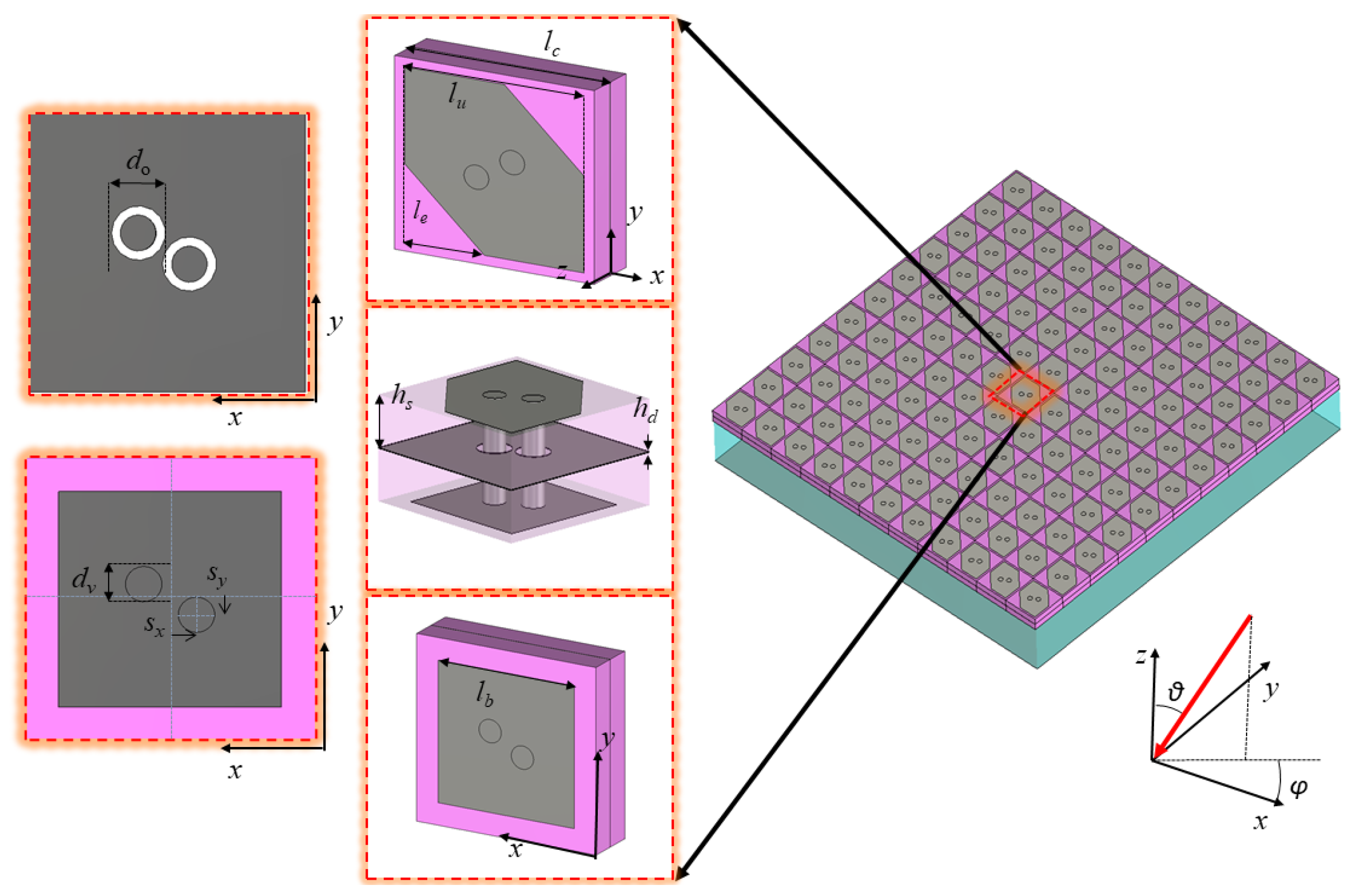
Figure 2.
Comparison among phases of the PCM reflection coefficient. While the black solid line represents the optimized case, dotted and dashed lines stand for sub-optimal steps with variations on dimensions of the transmitting patch and of the via holes.
Figure 2.
Comparison among phases of the PCM reflection coefficient. While the black solid line represents the optimized case, dotted and dashed lines stand for sub-optimal steps with variations on dimensions of the transmitting patch and of the via holes.
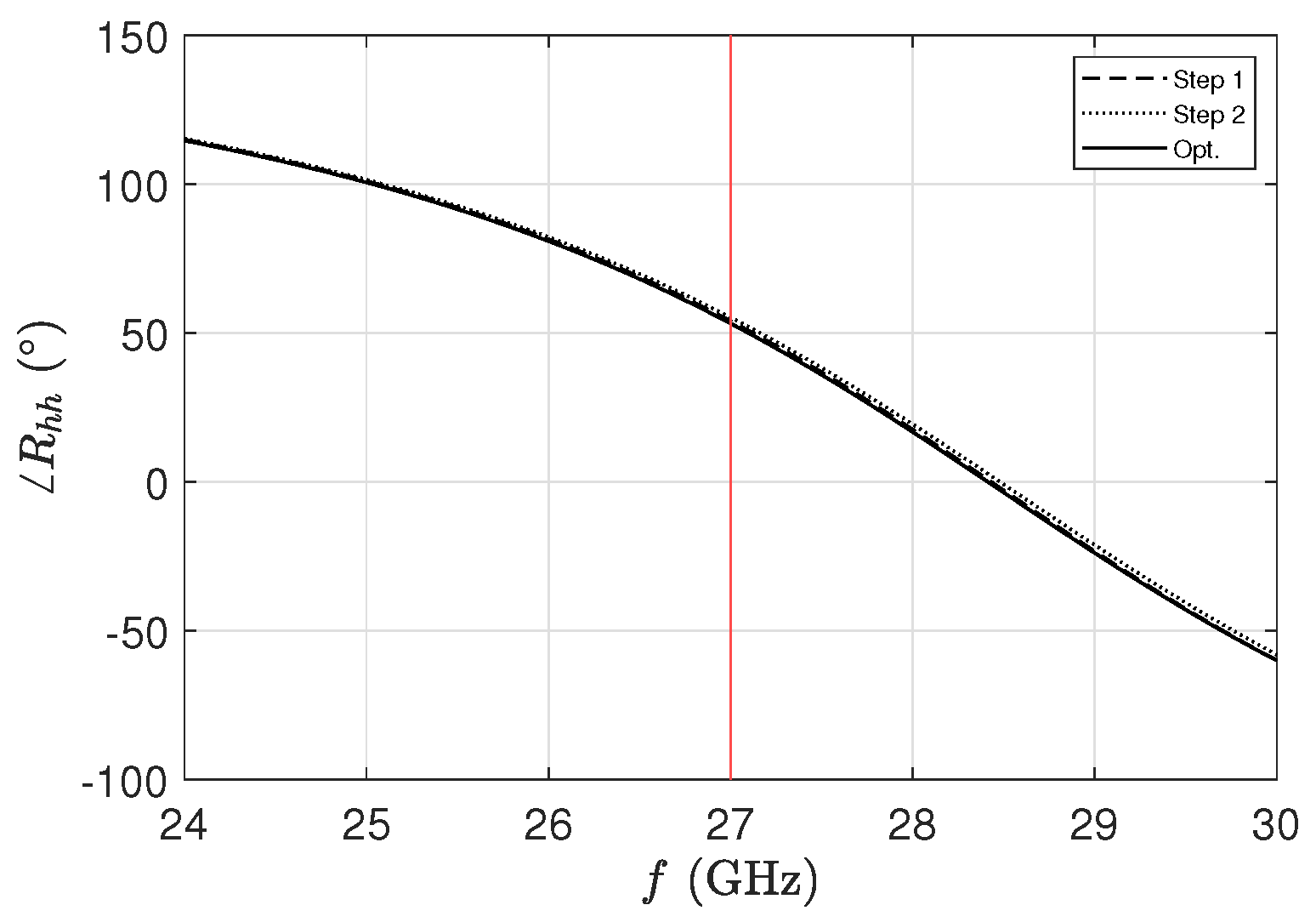
Figure 3.
By exploiting the reciprocity theorem, the absolute value of the cavity antenna far-field component is reported in dB through a colormap normalized with respect to its maximum for different elevation and azimuth angles for a working frequency f equal to (a) 27 GHz, (b) 27.3 GHz, (c) 28 GHz, (d) 28.2 GHz, and (e) 28.5 GHz. Magenta and black isolines represent the 3 dB axial-ratio (AR) level and the half-power beamwidth (HPBW) regions, respectively. Figure (f) shows the different AR response of the PCM in a free-standing configuration (not placed above any cavity).
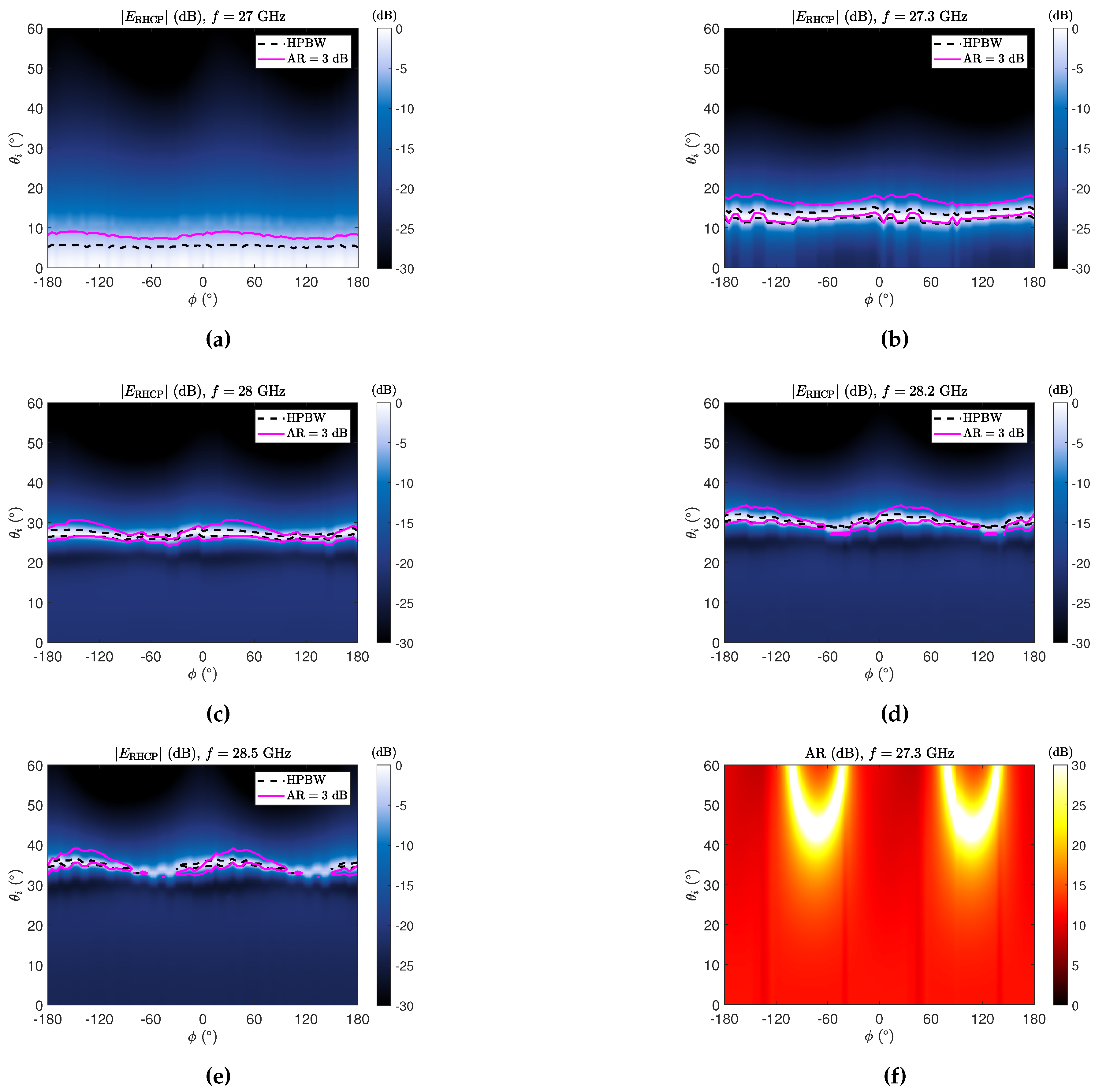
Figure 4.
radiation-pattern colormaps obtained through the proposed array-fed FPCA pointing at (a) and , (b) and , and (c) and . The black dashed and magenta solid lines represent the HPBW and dB boundaries, respectively.
Figure 4.
radiation-pattern colormaps obtained through the proposed array-fed FPCA pointing at (a) and , (b) and , and (c) and . The black dashed and magenta solid lines represent the HPBW and dB boundaries, respectively.
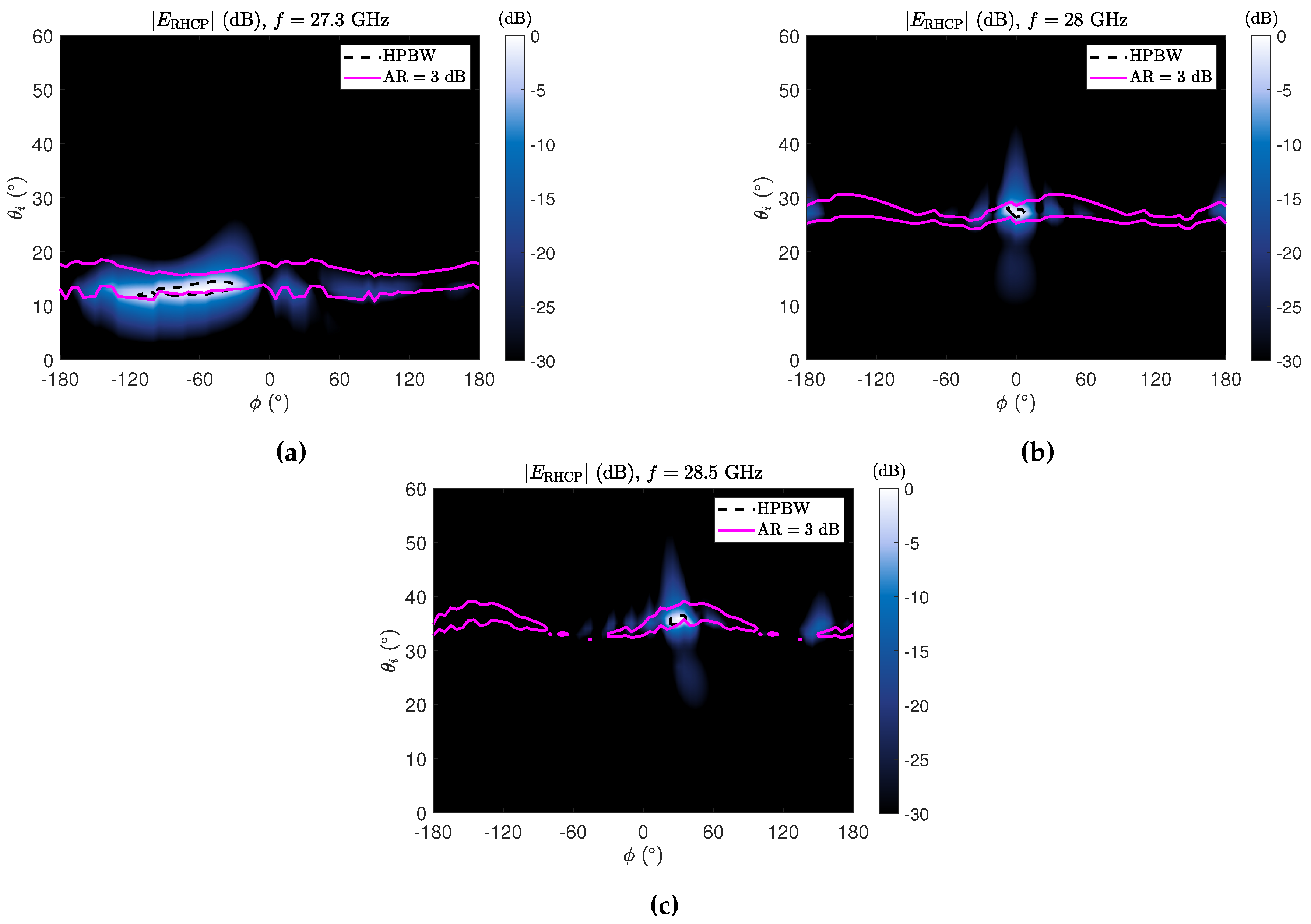

Table 1.
Unit-cell design parameters.
| (mm) | (mm) | (mm) | (mm) | (mm) |
| 3.33 | 3 | 1.33 | 2.53 | 0.46 |
| (m) | (mm) | (mm) | (mm) | (mm) |
| 5.20 | 0.415 | 0.634 | 0.18 | 0.3 |
Disclaimer/Publisher’s Note: The statements, opinions and data contained in all publications are solely those of the individual author(s) and contributor(s) and not of MDPI and/or the editor(s). MDPI and/or the editor(s) disclaim responsibility for any injury to people or property resulting from any ideas, methods, instructions or products referred to in the content. |
© 2024 by the authors. Licensee MDPI, Basel, Switzerland. This article is an open access article distributed under the terms and conditions of the Creative Commons Attribution (CC BY) license (http://creativecommons.org/licenses/by/4.0/).
Copyright: This open access article is published under a Creative Commons CC BY 4.0 license, which permit the free download, distribution, and reuse, provided that the author and preprint are cited in any reuse.


