
Submitted:
06 January 2025
Posted:
07 January 2025
You are already at the latest version
Abstract
The highway network is densely distributed in the southeast coast of China. Highway subgrades passing through soft soil areas often produce large settlements, resulting in pavement cracking, bridgehead jumping and other diseases. In order to study the effect of three trenchless treatment technologies of oblique jet grouting pile (JGP), lateral displacement limiting pile (LDLP) and load reducing pipe (LRP), centrifugal model tests were carried out under three treated conditions and without treatment. Based on the data of pore water pressure and settlement in the range of half embankment model and outside the embankment, the settlement characteristics of highway soft soil foundation during the test simulation were studied, and the characteristics of different treatment methods were compared. The high level of pore water pressure corresponds to the rapid development of settlement. The average settlement during the existing operation period accounts for 96.7% of the total settlement of the simulation period, and the settlement does not converge. The methods can effectively inhibit the development of settlement and each has its own characteristics: LRP method does not involve foundation treatment, so its settlement char-acteristics are closest to that without treatment. The LDLP method can obviously limit the set-tlement within the embankment range and the pore water dissipation. The JGP method enhances the synergistic deformation ability of the embankment and effectively decreases the differential settlement.
Keywords:
Soft soil
; Subgrade
; Centrifugal model test
; Foundation treatment
; Settlement
1. Introduction
Marine soft soil is widely distributed in the southeast coast of China and it is buried deep, and the artificial construction and reclamation of coastal areas have also produced a large number of coastal marine sedimentary soft soil [1,2]. Soft soil has the characteristics of large natural void ratio and high compressibility [3], low coefficient of consolidation and non-uniform consolidation [4,5], poor permeability and high natural water content [6], low shear strength and high sensitivity, which makes it unable to become a reliable filler or foundation in natural state [7,8,9]. China 's expressway network is densely distributed in the southeast coastal area, and the rapid economic development has also brought about a significant increase in traffic volume. Some expressways crossing soft soil areas have experienced engineering problems such as excessive foundation settlement after long-term operation [10,11,12]. For soft soil foundation, soil improvement or foundation treatment must be carried out [13,14,15,16].
However, the soft soil foundation treatment of the in-service expressway is completely different from the treatment of the new project, mainly because the trenchless treatment technology is needed to complete the reinforcement of the subgrade under the condition of ensuring the normal or partial operation of the expressway. The corresponding trenchless treatment technology needs to have the characteristics of short construction period, less occupation of construction site and having less impact on the surrounding area. In addition, it also needs to be convenient for quality inspection. At present, many experts and scholars have focused on the study of trenchless treatment technology to meet the needs of old house reconstruction, advanced geological reinforcement before excavation and subgrade reinforcement of in-service highways and railways [17,18,19,20].
Considering the long period of soft soil deformation and the indistinguishable compression deformation, rheology and lateral extrusion in its overall deformation, a reliable method for predicting its settlement is needed. At present, the main methods to predict its deformation are model test and numerical simulation [21,22], and there are also cases of calculating settlement by deriving theoretical formulas and modifying empirical formulas based on measured data [23,24]. In addition, some scholars have adopted the method of curve fitting combined with numerical simulation to predict the settlement. In the comparison, it is concluded that the settlement obtained by Flac3D numerical simulation is often larger than the real value, which is more suitable for conservative prediction before construction [25]. The parameters required for numerical simulation are usually difficult to obtain, and due to various technical, economic and geographical constraints, small-sample characteristics will be caused [26]. For the settlement prediction after trenchless treatment, when using numerical analysis, if the interaction between pile and soil cannot be well simulated, or the appropriate permeability and consolidation model or parameters cannot be selected, the results may not be accurate enough. Therefore, it is best to use the method of model test to evaluate the effect of treatment and compare the treatment methods.
Geotechnical centrifuge test is a model test that can effectively obtain the physical response of the structure in the real environment. It is often used for settlement prediction, failure mode analysis, results comparison and method comparison [27,28,29,30]. The centrifugal model test is based on the principle of centrifugal inertia force and gravity equivalence, and the gravity field is simulated by means of centrifugal force field. Compared with theoretical analysis, numerical simulation and field investigation, using centrifugal model test to predict the settlement after treatment has the advantages of maintaining the authenticity of the material, controllable parameters and processes, reproducible phenomena and high efficiency [31,32,33]. In method design, centrifugal test is often used to determine the parameters such as pile length and spacing, anchoring angle and length of anchor rod, but it rarely involves the comprehensive comparison of different methods.
Based on the treatment of deep soft soil foundation of in-service expressway, this research took the three feasible trenchless treatment methods as the research object, namely oblique jet grouting pile (JGP) method, lateral displacement limiting pile (LDLP) method and load reducing pipe (LRP) method. Through the centrifugal model test, three treatment methods were simulated to study the developing trend of pore water pressure and settlement below the embankment and outside the embankment range within 5 years in the operation period after treatment. The feasibility of the treatment method was evaluated comprehensively, and the treatment effects of the selected methods were compared.
2. Test Scheme
2.1. Project Information and Soft Soil Foundation Treatment Scheme
This study relies on the soft soil foundation treatment project of the bridge head section of Zhi-Shang-He Bridge of Yong-Tai-Wen Expressway. A large area of marine soft soil is distributed below the transition section of the bridge, and the thickness of soft soil is more than 30 m. In the early stage of construction, the foundation treatment methods such as overload preloading, vacuum preloading and secondary excavation were first used. However, the settlement of the soft soil foundation could not remain stable and increased year by year, resulting in large deformation of the soft soil foundation at the bridgehead, bumping at the bridgehead, voiding and cracking of the bridgehead slab. For the purpose of maintaining operations, the existing embankment cannot be excavated, thus it is necessary to adopt a treatment method that can decrease the settlement without excavating the embankment and the surface. The construction equipment of jet grouting pile occupies less land and has little influence. It can be quickly constructed to form a pile body, and directly reinforce the soft soil to limit its subsidence and lateral deformation [34]. In addition, according to the existing reliable calculation model, it can also be known that the total settlement of soft soil foundation can be directly reduced by reducing the external load through various methods [35,36]. For example, the rammer pipe is used to replace the embankment soil to reduce the load, and the construction of rammer pipe has little influence on the environment surrounded, which is economical and safe. In order to solve the problem of soft soil foundation settlement in the transition section of road and bridge, three feasible treatment methods, namely JGP method, LDLP method and LRP method, were selected.
The cross-sectional profiles of the three construction methods are shown in Figure 1. The section spacing of the JGP method is 2 m, and the area replacement rate is 8.61%. The section spacing of LDLP method is 2.8 m, the piles are distributed in triangles, and area replacement rate is 6.41%. The section spacing of LRP method is 1.4 m, and the load reduction rate is 4.27%.
2.2. Scheme Design
The test equipment is Chang' An University TJL-3 geotechnical centrifuge model test system, which has the maximum capacity of 60 g.t, effective radius of 2.0 m and large model box actual volume: 700 × 360 × 500 mm3. The centrifugal acceleration set in the test is 70 g. The corresponding scale is shown in Table 1. Centrifugal model test set 1 group of control test and 3 groups of foundation treatment model tests. The control group without treatment measures was set up as a comparison to simulate the settlement of the existing operation period of the embankment (19 years). The cumulative settlement value of the 19th year of the simulation was recorded as the starting point of the other three groups, and the settlement of the condition without treatment in the following 5 years was predicted. The lateral displacement limiting piles, load reducing pipes and jet grouting piles were pre-buried in the model and then kept the machine running. When the settlement was consistent with the record settlement dates of the control group (The error is controlled within 5%, based on the settlement of the middle line of the embankment), the formal tests started. The settlement and pore water pressure developing trends in the next five years after foundation treatment were recorded [37]. The corresponding test schemes are shown in Table 2. Figure 2 shows the model sketch of centrifugal test.
2.3. Test Material
In order to clarify the geological conditions of the bridgehead foundation, the soil samples at different depths of the site were sampled by drilling, and a series of tests were carried out to obtain the physical and mechanical properties of the soft soil. The properties are shown in Table 3. The soft soil 3 ‒ 5 m away from the surface was excavated to configure the remolded soil sample for the test. The remolded soft soil of the foundation has a wet density ρw of 1.72 g/cm3, a moisture content w of 55%, and specific gravity of soil particle Gs of 2.74. The deformation of embankment soil is tiny, thus, it is not necessary to use the soil of the actual embankment, only need to take the sand soil with particle size no greater than 12 mm into simulation. The optimum moisture content w of 13.08% was obtained by indoor compaction test and the remolded embankment soil obtained the maximum dry density ρdmax of 1.84 g/cm3 accordingly.
The PVC pipe with an outer diameter of 9 mm and a thickness of 1 mm was selected for the simulation of ramming pipes and piles. The LDLPs were simulated to form lateral restraints on the soil. The length is 360 mm and the spacing is 4 cm to obtain approximate foundation replacing rate and bending stiffness. When simulating the LRP, the condition of similar load reduction rate was satisfied. The spacing of the pipe is 20 mm. When simulating the JGP, the principle of foundation replacing rate was taken as the control condition. The length is approximately 20, 28.5 and 40 cm, and the pile spacing is 31.5 mm.
According to regulations, the standard value of the uniform load of the lane load qk is 14 kN/m2, and the lateral load reduction coefficient of the two lanes is 1.0. The lane load is equivalent to the quality of 2.939 kg of filling soil, which was simulated by iron plate.
2.4. Data Acquisition Equipment and Test Process
Shown in Figure 2 d, the laser displacement transducers were used to measure the settlement of the middle line of the embankment, middle line of the half embankment surface, the top of the embankment slope, the foot of the embankment slope and the 11 cm outside the foot of the embankment slope (outside the embankment range), numbered as DT1 ‒ DT5 in order. Each running time of equipment is 2.5 h and the settlement data was recorded after each operation. The pore water pressure sensors were arranged horizontally on the middle line of the half embankment surface (It will be called measuring point below the embankment) and 5 cm on both sides of foot of the embankment slope (They will be called measuring points below the embankment slope and measuring points outside the embankment range in the following text), and vertically buried under 5, 20 and 30 cm below the foundation surface of the model, numbered as WP1 ‒ WP9. A total of 3 × 3 = 9 pore water pressure sensors were used and the acquisition frequency is 2 Hz.
The test process is as follows and also shown in Figure 3:
- (1)
- Natural consolidation simulation: The soft soil was remolded, weighed and filled into the large model box, compacted equably. After the subgrade model was put into the centrifuge, the centrifuge kept operating until the thickness of the soft foundation reached the predetermined height. It can be considered that the soft soil model had the same degree of consolidation as the site. Then took out the model and simulated the embankment filling.
- (2)
- Settlement during the existing operation period: For control test, the model box was put into the centrifuge, and 2.5 h × 12 groups tests were operated under the acceleration of 70 g. The pore water pressure data was recorded through acquisition device during the operation and the settlement data after each operation was recorded. Additionally, after the 12 operations (simulated the operation period of 19 years), the settlement of the middle line of the embankment was recorded as the controlled condition, which is the start of the three foundation treatment method tests.
- (3)
- Settlement prediction: For three foundation treatment method tests, the pipes and piles were pre-buried into the soft soil foundation model or embankment. The whole model was put into the centrifuge and kept operating. Until the settlement reached the recorded controlled condition, the formal test started and 2.5 h × 4 groups tests were operated. For control test, it continued operation for the subsequent 2.5 h × 4 groups tests.
3. Results Analysis
3.1. Analysis of the Control Test
Figure 4 shows the developing trend of pore water pressure and settlement in the control test during the existing operation period and the subsequent 5 years without treatment. The pore water pressures all show several different stages:
- Pore water pressure rising stage: This stage is mostly the first four years of the simulation period. In this stage, the pore water pressures rise rapidly, together with the high speed of the consolidation, and the cumulative settlements of soil are the fastest. In the first four years, the pore water pressures rise to the peak, and the cumulative settlements recorded by the laser displacement transducer are the largest at this stage.
- Pore water pressure falling stage: The falling trends of pore water pressure in this stage are obviously different from that in the later stage of the curve. Because the pore water pressures are higher in the previous stage, at this time, its dissipation rate and consolidation rate are both faster. The data of DT1 ‒ DT4, which are within the embankment range, show that the settlement developing rates are slower than that of the first stage, but they are still obviously different from the later stage. The key point is, in the duration of this stage, the developing trends of settlement and pore water pressure vary with the measuring point of the subgrade.
WP7 is located 5 cm below the embankment, making it subjected to the largest pressure, so its pore water pressure is also the easiest to dissipate. It can be seen that WP7 remains its’ falling trend from 3rd year to 13th year, and the falling rate of it is also significantly higher than that of other measuring points in the subsequent stage.
WP1 and WP4 measuring points are located 30 cm and 20 cm below embankment, which are subjected to greater pressure than other measuring points at the same depth. Their pore water pressures dissipate faster, and the starting points of their decline stages are also earlier than other measuring points. Their decline trends start at the 2nd year to 3rd year and begin to weaken in the 7th year of the simulation period.
WP2, WP5 and WP8 are located 5, 20 and 30 cm blow the embankment slope, whose loads are less than those closer to the center of the embankment. They are on the dissipation path of the pore water from the center of the embankment. Therefore, their potential possibilities of dissipation are weak and the dissipation lasts for a long time. Their falling trends begin in the 3rd year to 4th year and end in the 8th year to 10th year, with a lower falling rate.
WP3, WP6 and WP9 are located 5, 20 and 30 cm blow the ground surface outside the embankment range, which are not directly subjected to the load from the embankment. Their potential possibilities of dissipation are lowest, for their values are generally smaller than the other measuring points in the embankment range. Additionally, they are also on the dissipation path of the pore water from the range of embankment, so the dissipation is slower. Therefore, their falling stages are short, starting from the 3rd year to 4th year and ending early in the 6th year to 8th year.
- 3.
- Pore water pressure gentle stage: In this stage, the development trends of pore water pressure are gentle, and most of them keep falling. The settlements of soft soil gradually tend to be slow, but there are no obvious convergence trends.
It is worth noting that the two measuring points of WP4 and WP6 show that the pore water pressures have the rising trend in the gentle section. The reasons are as follows: WP4 is below the embankment. Since the construction is completed, the pore water pressure rises and the settlement develops synchronously. After the dissipation of pore water pressure is completed to a large degree, in the gentle section, with the settlement of the upper soil, the pore water migrates downward, resulting in the rise in pore water pressure at WP4. WP6 is on the dissipation path, where the pore water passes through during the dissipation process. Because the permeability coefficient of soft soil is low and the load distributed there is less, the pore water at measuring point WP6 is not dissipated enough yet the pore water supplement from embankment range is obtained. Thus, it shows a rising trend.
As can be seen from Figure 4 d, settlement mainly occurs in the first 5 years of operation, and then the settlement develops slowly yet does not show an obvious convergence trend, so the subsequent settlement cannot be ignored. Table 4 shows the settlement data for simulated operation 24 years and controlled condition of the 19th year. In the 24 years simulated by the control test, the average proportion of settlement during the existing operation period was as high as 96.7%. The settlement of subgrade decreases from the center to both sides, and the differential settlement outside the embankment range increases obviously. Considering the lateral extrusion of soft soil, the soft soil outside the embankment has a tendency to uplift upward, so there is a large settlement difference.
3.2. Analysis of the Load Reducing Pipe Method Test
Figure 5 shows the developing trend of pore water pressure and settlement at each measuring point in the next 5 years after treated by LRP method. Except for WP6, the pore water pressure of each measuring point is in a decline state. Because the LRP method only reduces the upper load compared with the control test, the developing trends of pore water pressure of both tests are similar. The average pore water pressures of each measuring points are generally litter higher than that of the control test and dissipate slowly. They are still in the process of dissipation, and the load reduction only delays the occurrence of settlement.
The developing trends of the four measuring points within the embankment range are similar, and the settlement recorded by the measuring point outside the embankment range is obviously smaller than that of this four measuring points. Table 5 shows the cumulative settlement simulated by the LRP method after 5 years, the cumulative settlement of the control group accumulated since the 19th year and the comparation between them. It can be seen that the effect of load reduction is most effective in a certain range below the embankment, which is mainly subjected to the gravity load of the embankment and traffic load. According to DT1 and DT2, the reduction of settlement is most obvious that nearly half of the subsequent settlement is avoided. According to the settlement curve, the settlement does not show a convergence trend, although it is very effective in terms of settlement developing rate and settlement reduction. The LRP method has a significant effect in the short term, but considering the long-term consolidation characteristics of soft soil, it is necessary to pay attention to its future settlement, and it better be combined with grouting method and other construction methods.
3.3. Analysis of the Jet Grouting Pile Method Test
Figure 6 shows the developing trend of pore water pressure and settlement at each measuring point in the next 5 years after treated by JGP method. The pore water pressures of each measuring points are in decline states. Because the jet grouting pile directly reinforces the soft soil foundation compared with the control test, it increases the modulus and synergistic deformation ability of the foundation soil. It can be seen from the three measuring points of WP1, WP4 and WP7 at the middle line of the embankment that their pore water pressure curves are close to horizontal in the final 2 years of simulated operation. Compared with the control test and LRP method, the JGP method has shown its enhancing ability in the synergistic deformation of the soft soil under the embankment. It can be verified from the WP1, WP2, WP5, WP7, WP8 and WP9 within the reinforcement range, for the average falling rates of pore water pressure of these measuring points show little difference, while the pore water pressure falling rates of the LRP method and the control test are highly correlated with the soil depth. In addition, the WP6 measuring point is on the horizontal outward pore water dissipation path. On the one hand, it has pore water supplement from center of the embankment, on the other hand, the excess pressure caused by overlying load is low. The pore water there dissipates slowly but get supplied, showing the rising trend. WP2 and WP5, which are also on the dissipation path, are below the embankment slope. The loads are larger and the pore water pressures dissipate quickly, so the pore water pressure curves are still declining.
Similarly, Table 6 shows the cumulative settlement simulated by the JGP method and control test. It can be seen that the jet grouting pile can also effectively reduce the foundation settlement, and the percentages of settlement reduction of each measuring points are generally greater than LRP method. In addition, it is not difficult to see that the percentage of settlement reduction is generally decreasing from the center of the embankment to the outside. Because the closer to the center, the deeper depth of the soft soil jet grouting pile reinforce, and the formed piles can effectively transfer the embankment load to the deeper foundation and increase the synergistic deformation ability. Therefore, the effect of JGP method is most obviously shown in the middle line of the embankment and weakens with the distance to the it.
3.4. Analysis of the Lateral Displacement Limiting Pile Method Test
Similarly, Figure 7 shows the developing trend of pore water pressure and settlement of JGP method and Table 7 shows the cumulative settlement of it with the control test. Because the lateral displacement limiting piles hinder the dissipation of pore water pressure, making the effect of dissipation weakened, the pore water pressure outside the embankment is lack of supplement and shows a slight falling trend. The three buried sensors below the embankment slope show that pore water pressures develop relatively flat, which are different from the falling trend of the control test and the other two treatment methods. It can be seen that the LDLP method has the effect of limiting displacement and the pore water dissipating horizontally is gathered here. Therefore, the rise in the pore water pressure of WP2, WP5 and WP8 is significantly larger than that of other measuring points in the same depth. The measuring points WP3, WP6 and WP9 outside the embankment are less affected by the effect of pore water dissipation from center of the embankment, so the falling rate of pore water pressure increases with depth.
Settlement of five measuring points can be clearly distinguished between within the embankment range and outside the embankment range. The developing rules of settlement in DT1, DT2 and DT3 within the range of LDLP are similar, and there are approximate fluctuations. DT4 and DT5 record the settlement outside the range of piles, whose developing trends are relatively gentle, as the developing rates of settlement are decreasing. According to Table 8, the reducing settlements in the range of LDLP averagely accounts for the 44% that of the control test.
4. Error Analysis and Scheme Comparison
4.1. Error Analysis
The influence factors of centrifugal model test can be concluded as:
- The soil layer simulated by the experiment is thinner. The centrifugal acceleration of the model test is set as 70 g, which can take the soft soil layer of 28 m into consideration. However, the average thickness of the soft soil layer is not less than 30 m, and the silt clay layer is below it, whose settlement cannot be ignored. Therefore, taking this test scheme, the thickness of soft soil is thinner than that of practical project, which will lead to the small settlement measured by this test scheme.
- Boundary constraint effect. Under the of gravity load of embankment and traffic load, the soft soil has both vertical settlement and lateral deformation, and the boundary of the model box will limit the lateral deformation to a certain extent, resulting in a decrease in vertical settlement.
- Boundary friction effect. There is friction between the box and the soil, which will decrease the settlement. Though this effect can be weakened by applying lubricants such as Vaseline, but it still cannot be ignored
- Foundation filling effect. Due to the high moisture content of the simulated soft soil, there will be some voids in the artificial filling process, which will lead to the failure to restore the degree of consolidation of the natural soft soil layer, resulting in a slightly larger settlement.
Based on the above analysis, these different influencing factors will result in the simulated settlement smaller than actual, which is a systematic error. However, even with this discrepancy, it is still possible to clearly differentiate the effects of these treatment methods through pore water pressure and settlement, allowing for comparison between the methods.
4.2. Treatment Method Comparison
In order to comprehensively evaluate each foundation treatment method, the following two factors are mainly considered: 1. Reduce settlement in existing and subsequent operation period. 2. Pavement integrity evaluation.
The demonstration site of Yong-Tai-Wen Expressway is not only in the area with deep soft soil foundation, but also near the bridgehead, so it is necessary to pay special attention to the settlement difference, in addition to the development of settlement in the subsequent operation. The settlement difference should not be too large, otherwise it will also lead to diseases such as pavement cracking.
Table 8 shows the average falling rates of pore water pressure in 5 years, including the condition without treatment and using three treatment methods. In terms of reducing settlement, all three methods can effectively reduce the settlement, and the effect is obvious within the embankment range. The closer to the center of the embankment and the nearer to the surface, the greater the pressure there is, and the more likely it is to cause settlement. For the measuring points WP3, WP6 and WP9 that are close to the surface, the pore water pressure falling rates of three methods are significantly lower than that of the control test, which proves that three treatment methods can decrease the settlement in where main settlement occurs. In addition, it can be seen that the falling rates of measuring points (WP1, 2, 5, 7 and 8) within the reinforced range of the JGP are relatively average. For LRP method, the overall falling rates becomes smaller. The falling rates in WP2, WP5 and WP8 are low, because that is where the LDLP set and it hinders the pore water dissipation.
The effect of these methods can be presented through Figure 8 and Figure 9. Figure 8 shows the rising trend of the settlement difference in four measuring points compared with the settlement of the middle line of embankment, including condition without treatment and using three treatment methods. The main consolidation area of soft soil foundation will transfer to the deeper layer and both sides of the embankment with the development of settlement, and the settlement value is highly corresponding to the pressure it is subjected to. Thus, it can be seen that in the natural state it will lead to a large settlement difference, but as the consolidation of soft soil in the embankment is largely completed, the area where the main settlement occurs is shifting outwards the embankment, which can be verified by the rising rates of the settlement difference are decrease in four measuring points.
Figure 9 shows the settlement reduction of each method compared with the condition without treatment at the end of the test. Because the rammer pipe does not reinforce the soft soil foundation, the settlement still occurs below the embankment and the settlement is small compared with the control test, and the lateral deformation effect is weak. The lateral deformation is essentially the extrusion of soft soil to both sides of the embankment, which may cause the soil to have an upward uplift trend. The combined effect of this uplift trend and the trend of vertical deformation caused by soft soil consolidation is finally manifested as the settlement recorded. Although the settlement within the embankment can be effectively reduced, the settlement reduction of LRP method outside the embankment is the lowest in three treatment methods according to Figure 9. On one hand, the lateral deformation related to the uplift trend is weakened, on the other hand, LRP method does not involve soil reinforcement, which is closest to the settlement in natural state and will causes large settlement difference. The curves of settlement difference of LRP method are showing a rising trend in the end of the simulated operation period, and the rising rates are larger than that of WM condition.
Figure 10 shows the bending state of the PVC pipe simulating the LDLP at the end of the test. The LDLP limits the lateral extrusion of the soil, and also weakens the horizontal pore water dissipation. Its effect is obvious, for the uplift trend of the soft soil outside the embankment range is also weakened and the settlement there is larger, which can be seen in the existing large settlement difference in Figure 8. But these settlement difference curves are not showing the great rising trends in the end of the simulated operation period, that is due to the effect of reducing settlement within the embankment range. By forming the limitation to the soft soil foundation below the embankment, the load pressure subject to the range outside the embankment is decreased, resulting in lower consolidation and settlement there. The settlement outside the embankment is developing slowly and the settlement curve is almost horizontal according to Figure 7 ahead. Showing in the Figure 9, the settlement reduction of LDLP method is the highest in terms of the embankment range, which verifies the effect of LDLP method. With the consolidation of the soil below the embankment, the rising rate of settlement there is much lower than before and the rising trend of settlement difference is also weakened.
As far as the treatment effect of JGP method is concerned, its effect of decreasing settlement difference is the best. In the later stage of the simulated operation period, it has the smallest settlement difference, and the settlement difference is decreasing or its rising rate is the lowest of the four tests. In addition, the effect of reducing settlement is most significant in dealing with the settlement at the middle line of the embankment.
On the whole, in terms of decreasing settlement, LRP method has been very effective for simulated 5 years, but it may not be the optimal scheme according to the existing trend, for the settlement difference may develop. The LDLP method has more advantages in reducing the settlement outside the embankment and inhibiting the subsequent settlement. The effect of JGP method on synergistic deformation is obvious, which can be seen from the developing trends of settlement difference and pore water pressure. The model test can fully restore the physical feedback of the structure in the actual working conditions, and can effectively predict the settlement and compare the treatment methods, but it also has its defects: 1. Comprehensively evaluating the error factors, the settlement data predicted by the model test is lower than actual; 2. The mechanism analysis from the trend of settlement and pore water pressure better to be verified by other means. Therefore, the next work is to verify the results by means of numerical simulation and field measurement.
5. Conclusion
Centrifugal model test was used to simulate the effect of a series of treatment methods namely lateral displacement limiting pile, oblique jet grouting pile and load reducing pipe method. The developing trends of pore water pressure and settlement in 5 years were studied, and the following conclusions were drawn:
- Considering the thickness of simulated soft soil foundation, boundary friction effect, box boundary constraint effect and filling effect, the settlement recorded is lower than actual. However, the differences showing in the recorded pore water pressure and settlement between the various treatment methods in the test are obvious enough to support the comparison of the schemes.
- The high value of pore water pressure corresponds to the rapid development of settlement. The settlement simulated by the control test in 24 years developed rapidly in the first 3 ‒ 4 years, and mainly occurred in the existing operation period of 19 years, up to 96.7 %. However, at the end of the test, the pore water pressure remained to decrease, and the settlement curve did not converge. If not treated, a large subsequent settlement would occur. And there is a large settlement difference in its natural state, which also needs to be considered.
- The three treatment methods can effectively decrease the development of settlement. The settlements after treated by LRP, JGP and LDLP method in the 5 years are reduced by 32.79%, 38.04% and 41.45% respectively compared with that without treatment. In addition, the settlement curves of JGP and LDLP method have a convergence trend.
- The characteristics of the three methods are as follows: the LRP method has a good effect on reducing the settlement within the embankment range within 5 years of simulation, but the curve of the settlement difference is rising rapidly, and the subsequent settlement development has no obvious convergence trend. The LDLP method can best reduce the settlement within the embankment range, which is mainly manifested in hindering the horizontal dissipation of pore water and the lateral extrusion of soft soil. The JGP method can directly strengthen the integrity of the embankment, enhancing the synergistic deformation ability and reducing the settlement difference.
The settlement prediction and comparative analysis carried out by centrifugal model test in this study better to be further verified by monitoring data or numerical simulation, but it can open up the application of centrifugal model test in scheme comparison and selection, and can also provide ideas for other similar soft soil foundation trenchless treatment.
Author Contributions
Conceptualization, Xiaohua Yang; Methodology, Shasha Zhang; Software, Tiangong Zhang; Validation, Jianqiang Xu; Formal analysis, Tiangong Zhang; Investigation, Mengjie Wang; Resources, Jianqiang Xu; Data curation, Tiangong Zhang; Writing – original draft, Tiangong Zhang; Writing – review & editing, Tiangong Zhang and Mengjie Wang; Visualization, Shasha Zhang and Xiaohua Yang; Supervision, Shasha Zhang and Xiaohua Yang; Project administration, Shasha Zhang; Funding acquisition, Feng Xu.
Funding
This research is supported by China Postdoctoral Science Foundation (2024T170750).
Data Availability Statement
The data used to support the findings of this study are available from the corresponding author upon request. The data are not publicly available due to privacy.
Conflicts of Interest
Authors Jianqiang Xu and Feng Xu were employed by the company China Merchants Chongqing Communications Research and Design Institute Co., Ltd. The remaining authors declare that the research was conducted in the absence of any commercial or financial relationships that could be construed as a potential conflict of interest.
References
- He, J.; Luo, S.; Li, W.; Kang, D.; Zuo, Z. Capillary water absorption and strength of solidified marine soft soil. Construction and Building Materials 2024, 423, 135729. [Google Scholar] [CrossRef]
- Feng, S.; Lei, H. A settlement prediction model considering tidal loading and traffic loading of soft soil subgrade. Computers and Geotechnics 2022, 144, 104639. [Google Scholar] [CrossRef]
- Jiao, W.; Zhou, D.; Wang, Y. Effects of Clay Content on Pore Structure Characteristics of Marine Soft Soil. Water 2021, 13, 1160. [Google Scholar] [CrossRef]
- Zhou, Y.; Han, W.; Su, D.; Chen, X. Study of the Nonuniform Consolidation Characteristics of Soft Soils Using a Novel Model. Buildings 2023, 13, 3104. [Google Scholar] [CrossRef]
- Chai, J.; Zhou, Y. Method for Considering the Effect of Nonuniform Consolidation. American Society of Civil Engineers 2018, 18, 04017151. [Google Scholar] [CrossRef]
- Zhou, C.; Yu, L.; Huang, Z.; Liu, Z.; Zhang, L. Analysis of microstructure and spatially dependent permeability of soft soil during consolidation deformation. Soils and Foundations 2021, 61, 708–733. [Google Scholar] [CrossRef]
- Zheng, J.; Hu, X.; Gao, S.; Wu, L.; Yao, S.; Dai, M.; Wang, J. Undrained cyclic behavior of under-consolidated soft marine clay with different degrees of consolidation. Marine Georesources & Geotechnology 2022, 42, 176–183. [Google Scholar] [CrossRef]
- Xiao, W.; Wu, K.; Xu, W.; Liu, Y.; Lu, H.; Chen, R. Experiment and analysis on dynamic characteristics of marine soft clay. Marine Georesources & Geotechnology 2024, May, 1–21. [CrossRef]
- Wang, Z.; Wang, W.; Peng, H.; Ha, J. Mechanical characteristic test of structural marine soft clay under complex stress paths. Journal of Railway Science and Engineering 2023, 20, 2868–2877. https://link.cnki.net/doi/10.19713/j.cnki.43-1423/u.t20221667.
- Wu, T.; Jin, H.; Guo, L.; Sun, H.; Tong, J.; Jiang, Y.; Wei, P. Predicting method on settlement of soft subgrade soil caused by traffic loading involving principal stress rotation and loading frequency. Soil Dynamics and Earthquake Engineering 2022, 152, 107023. [Google Scholar] [CrossRef]
- Wang, C.; Xie, L.; Liu, Z.; Wu, M.; Zhang, T.; Cai, G.; Liu, S. Study on settlement deformation law of new and old subgrade of expressway reconstruction and expansion based on CPTU. Transportation Geotechnics 2024, 49, 101392. [Google Scholar] [CrossRef]
- Wu, C.; Zhang, D.; Xia, H.; Luo, J.; Huang, H.; Qin, D. Embankment deformation characteristics analysis of an expressway widening project near a pond. Sci Rep 2023, 13, 717. [Google Scholar] [CrossRef]
- Arul, A.; Mohammadjavad, Y.; Mahdi, M.D.; Suksun, H.; Myint, W.B.; Melvyn, L. Evaluation of fly ash- and slag-based geopolymers for the improvement of a soft marine clay by deep soil mixing. Soils and Foundations 2018, 58, 1358–1370. [Google Scholar] [CrossRef]
- Said, K.N.M.; Rashid, A.S.A.; Osouli, A.; Latifi, N.; Yunus, N.Z.M.; Ganiyu, A.A.; Adekunle, G.A. Settlement Evaluation of Soft Soil Improved by Floating Soil Cement Column. International Journal of Geomechanics 2019, 19, 04018183. [Google Scholar] [CrossRef]
- Wang, M.; Yang, J.; Wu, Y.; Lu, Y. Rapid predictive method for the deterioration depth of cement solidified marine soft soil. Soils and Foundations 2024, 64, 101494. [Google Scholar] [CrossRef]
- Wong, R.K.N.; Weng, Y.F.; Leong, G.K.; Cheng, S.H. A Case Study of Effectiveness of Large Diameter Jet Grout for Soil Improvement Works in Soft Marine Clay. Lecture Notes in Civil Engineering 2020, 62, 649–655. [Google Scholar] [CrossRef]
- Wang, Z.; Xu, W.; Xu, Q.; Wang, Y.; Zhu, Y. Research on Temperature Field of Cement-Mixing Pile-Reinforced Soft Soil Foundation. Buildings 2024, 14, 845. [Google Scholar] [CrossRef]
- Zhang, Q.; Zhang, X.; Zhou, S.; Zhang, K.; Chen, F. Effect and evaluation model of adjacent pile construction on high-speed railway piers in soft soils. Structures 2024, 70, 107687. [Google Scholar] [CrossRef]
- Wang, T.; Liu, X.; Liu, L.; Xiong, W.; Li, Z. Research on the Reinforcement Effect and Bearing Characteristics of High-Pressure Jet-Grouting Piles on Covered Road Composite Ground in Landfill Sites. Buildings 2024, 14, 444. [Google Scholar] [CrossRef]
- Wang, S.; Yin, H.; Duan, Q.; Wang, H.; Li, Q.; Li, Z. Experimental study on vertical bearing mechanism of jet grouting jacked steel composite piles in low-clearance environments [OL]. Chinese Journal of Geotechnical Engineering. https://link.cnki.net/urlid/32.1124.TU.20240923.1548.004.
- Xie, W.; Zhang, Q.; Zhu, W. Numerical investigation on the effect of repeated surface surcharge loading on soil deformation and tunnel displacement in structured soft clay. Soil Dynamics and Earthquake Engineering 2024, 181, 108657. [Google Scholar] [CrossRef]
- Pandey, B.K.; Rajesh, S.; Chandra, S. Numerical Analysis of Soft Soil Reinforced with Geogrid Encased Stone Column. Lecture Notes in Civil Engineering 2022, 195, 65–72. [Google Scholar] [CrossRef]
- Cao, F.; Ye, C.; Wu, Z.; Zhao, Z.; Sun, H. Settlement Calculation of Semi-Rigid Pile Composite Foundation on Ultra-Soft Soil under Embankment Load. Buildings 2024, 14, 1954. [Google Scholar] [CrossRef]
- Lee, H.; Kim, S.-J.; Kang, B.-H.; Lee, K.-S. Long-Term Settlement Prediction of Ground Reinforcement Foundation Using a Deep Cement Mixing Method in Reclaimed Land. Buildings 2022, 12, 1279. [Google Scholar] [CrossRef]
- Cui, K.; Yang, W. Prediction Soft Soil Settling Using a Combination Method. Xinan Jiaotong Daxue Xuebao/Journal of Southwest Jiaotong University 2017, 52, 926–934. [Google Scholar] [CrossRef]
- Bao, X.; Li, J.; Shen, J.; Chen, X.; Zhang, C.; Cui, H. Comprehensive multivariate joint distribution model for marine soft soil based on the vine copula. Computers and Geotechnics 2025, 177, 106814. [Google Scholar] [CrossRef]
- Chen, T.; Zhang, G. Centrifuge modeling of pile-supported embankment on soft soil base for highway widening. Soils and Foundations 2024, 64, 101422. [Google Scholar] [CrossRef]
- Liu, H.; Luo, Q.; EI Naggar, M.H.; Zhang, L.; Wang, T. Centrifuge Modeling of Stability of Embankment on Soft Soil Improved by Rigid Columns. Journal of Geotechnical and Geoenvironmental Engineering 2023, 149, 04023069. [Google Scholar] [CrossRef]
- Chen, S.; Guan, Y.; Dai, J. Behaviour of anchored sheet pile quay stabilized with deep cement mixing columns in soft soil: Centrifuge and numerical modelling. Computers and Geotechnics 2023, 160, 105504. [Google Scholar] [CrossRef]
- Hu, J.; Weng, X.; Yang, L.; Lei, S.; Niu, H. Centrifugal modeling test on failure characteristics of soil-rock mixture slope under rainfall. Engineering Failure Analysis 2022, 142, 106775. [Google Scholar] [CrossRef]
- Shojaeian, A.; Sivakumaran, S.; Muraleetharan, K.K. Nonlinear Seismic Response Analysis of Pile Foundations Interacting with Improved and Unimproved Soft Clay. Journal of Geotechnical and Geoenvironmental Engineering 2024, 150, 04024106. [Google Scholar] [CrossRef]
- Jiang, Y.; Li, S.; He, N.; Xu, B.; Fan, W. Centrifuge Modeling Investigation of Geosynthetic-Reinforced and Pile-Supported Embankments. International Journal of Geomechanics 2024, 24, 04024147. [Google Scholar] [CrossRef]
- Fisonga, M.; Hu, Y.; Han, S.; Deng, Y.; Kaunda, R.B. Numerical-geostatistical-based approach to investigate the earth pressure evolution within the large grid wall foundation under adjacent surcharge loading. Computers and Geotechnics 2024, 167, 106056. [Google Scholar] [CrossRef]
- Shan, Y.; Luo, J.; Wang, B.; Zhou, S.; Zhang, B. Critical application zone of the jet grouting piles in ‘the vicinity of existing high-speed railway bridge in deep soft soils with medium sensibility. Soils and Foundations 2024, 64, 101407. [Google Scholar] [CrossRef]
- Xu, Y.; Zhang, J.; Liu, Z.; Cui, P. Calculation model for settlement of soft soil foundation with continuous drainage boundary considering the Hansbo’s flow law and the linear load. Environ Earth Sci 2024, 83, 579. [Google Scholar] [CrossRef]
- Shu, X.; Wang, Z.; Peng, Y.; Zhou, Z.; Tian, Y. A novel elasto-viscoplastic constitutive model for predicting the embankment settlement on soft structured clay. Computers and Geotechnics 2024, 167, 106093. [Google Scholar] [CrossRef]
- Zhang, N.; Li, B.; Wang, T.; Jiang, J.; Wang, H. Centrifugal model tests on stability of embankment on soft soil foundation. Chinese Journal of Geotechnical Engineering 2023, 45, 222–225. [Google Scholar] [CrossRef]
Figure 1.
Embankment and soft soil foundation cross-sectional profiles of: (a) JGP method; (b) LDLP method and (c) LRP method.
Figure 1.
Embankment and soft soil foundation cross-sectional profiles of: (a) JGP method; (b) LDLP method and (c) LRP method.
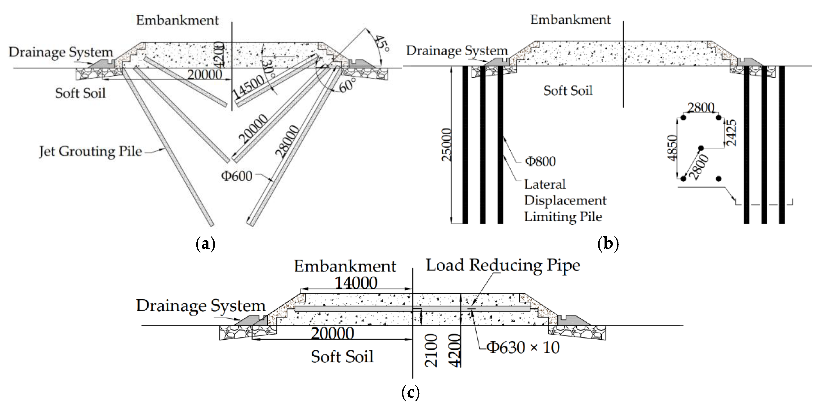
Figure 2.
Centrifugal test model sketch of: (a) LDLP method; (b) LRP method; (c) JGP method, and (d) model sizes and measuring instrument scheme.
Figure 2.
Centrifugal test model sketch of: (a) LDLP method; (b) LRP method; (c) JGP method, and (d) model sizes and measuring instrument scheme.
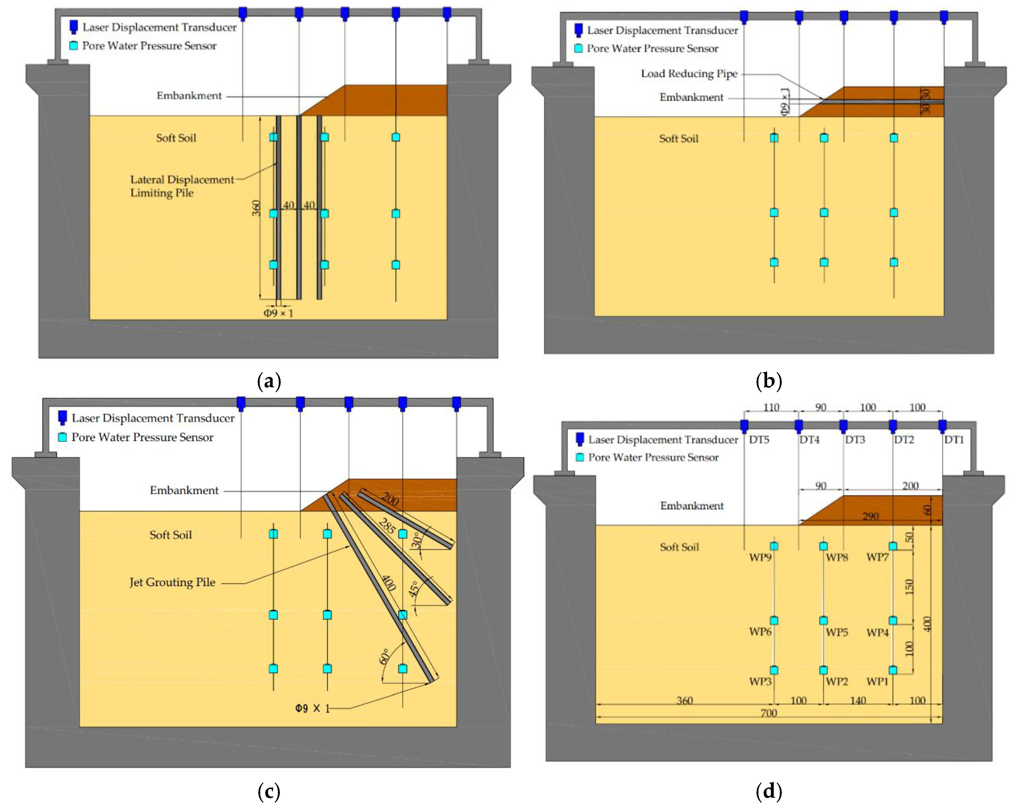
Figure 3.
Test procedures of: (a) labeling model box size; (b) embedding sensors; (c) pre-burying simulated piles; (d) preparing embankment soil; (e) filling embankment an simulating traffic load and (f) placing model box into centrifuge.
Figure 3.
Test procedures of: (a) labeling model box size; (b) embedding sensors; (c) pre-burying simulated piles; (d) preparing embankment soil; (e) filling embankment an simulating traffic load and (f) placing model box into centrifuge.
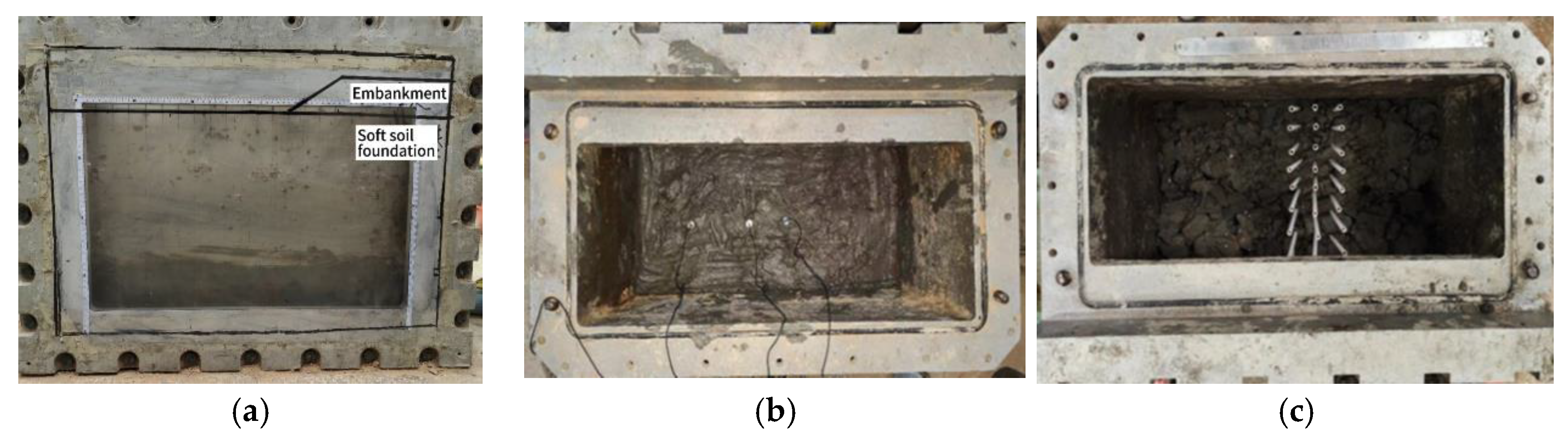
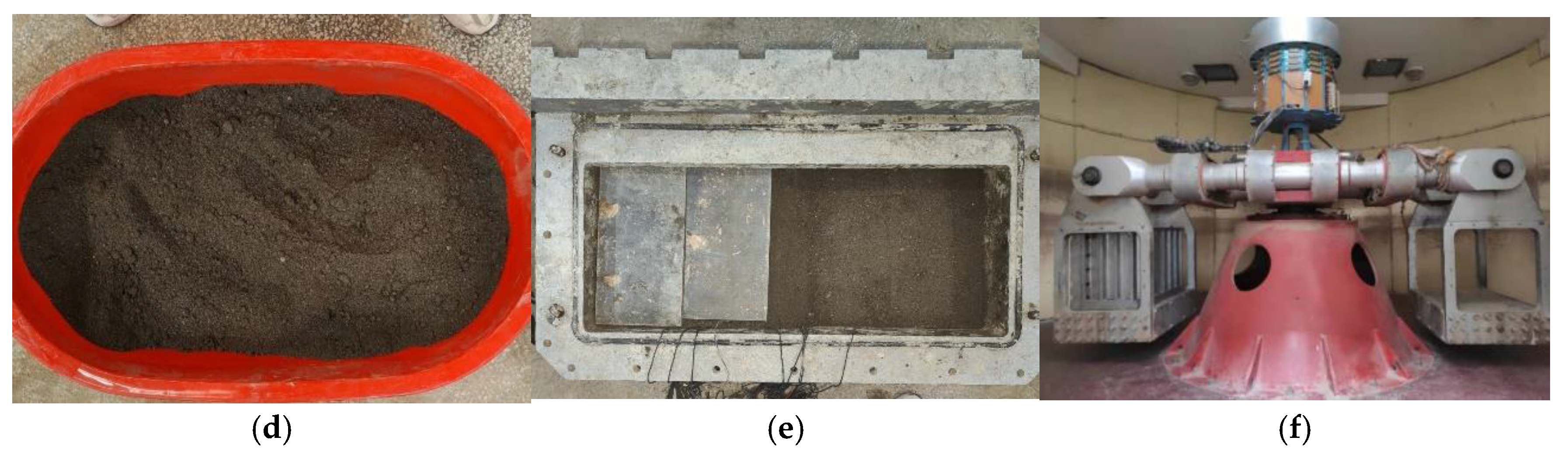
Figure 4.
Diagram of pore water pressure development: (a) below the embankment; (b) below the embankment slope; (c) outside the embankment range and (d) the diagram of settlement of the control test.
Figure 4.
Diagram of pore water pressure development: (a) below the embankment; (b) below the embankment slope; (c) outside the embankment range and (d) the diagram of settlement of the control test.
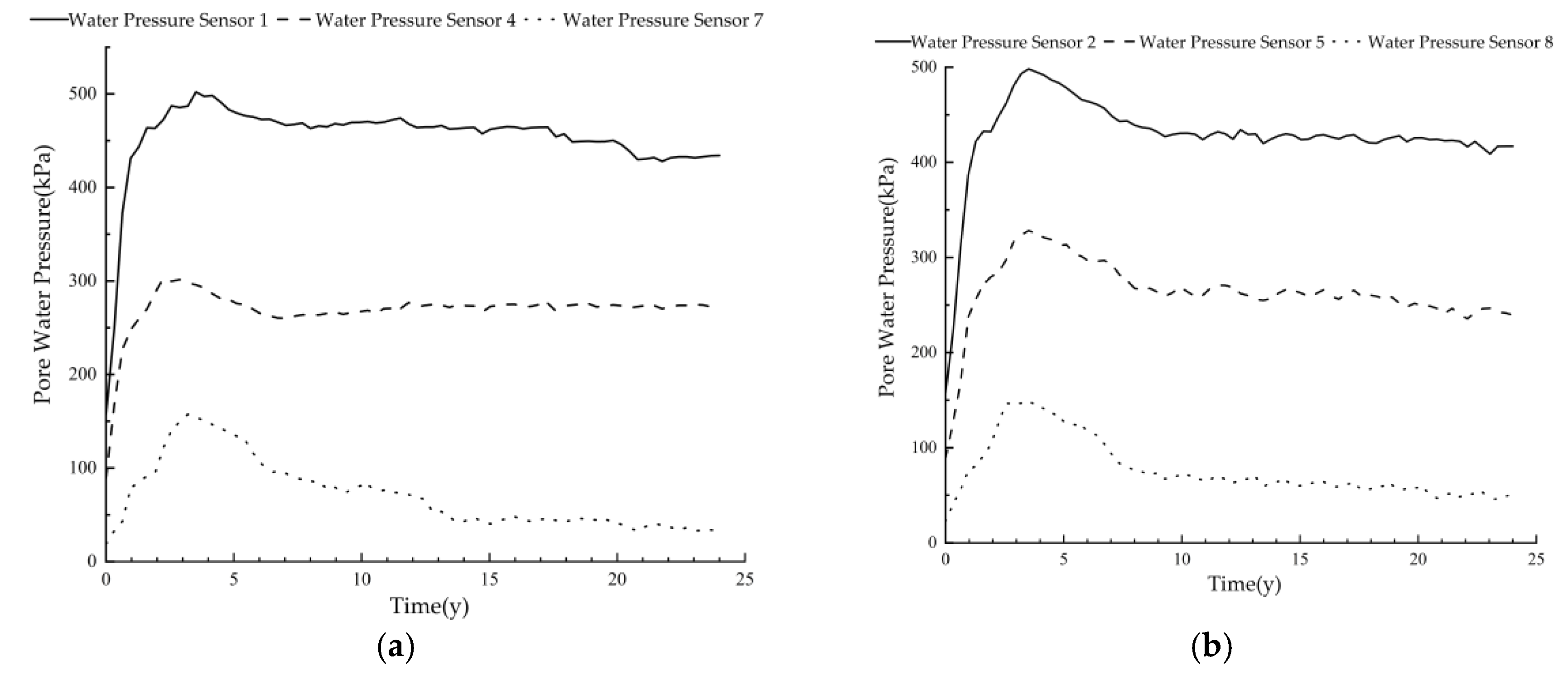
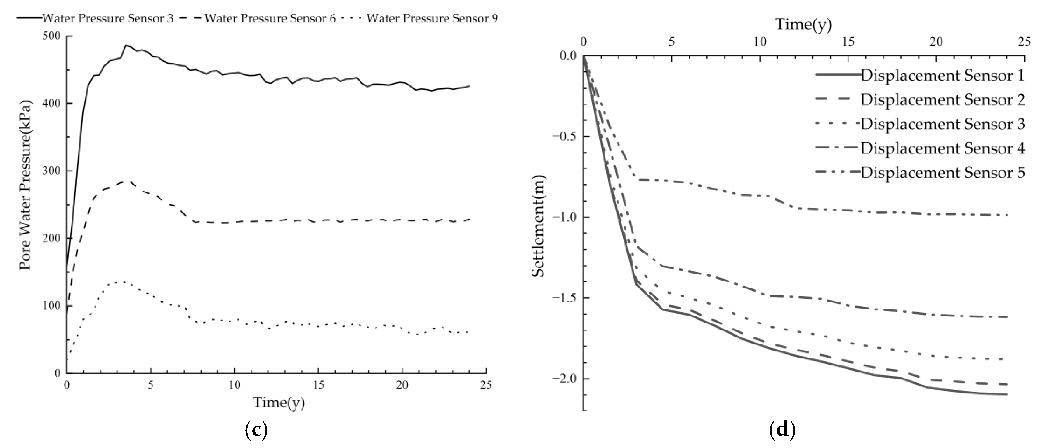
Figure 5.
Diagram of pore water pressure development: (a) below the embankment; (b) below the embankment slope; (c) outside the embankment range and (d) the diagram of settlement without treatment and treated by LRP method.
Figure 5.
Diagram of pore water pressure development: (a) below the embankment; (b) below the embankment slope; (c) outside the embankment range and (d) the diagram of settlement without treatment and treated by LRP method.
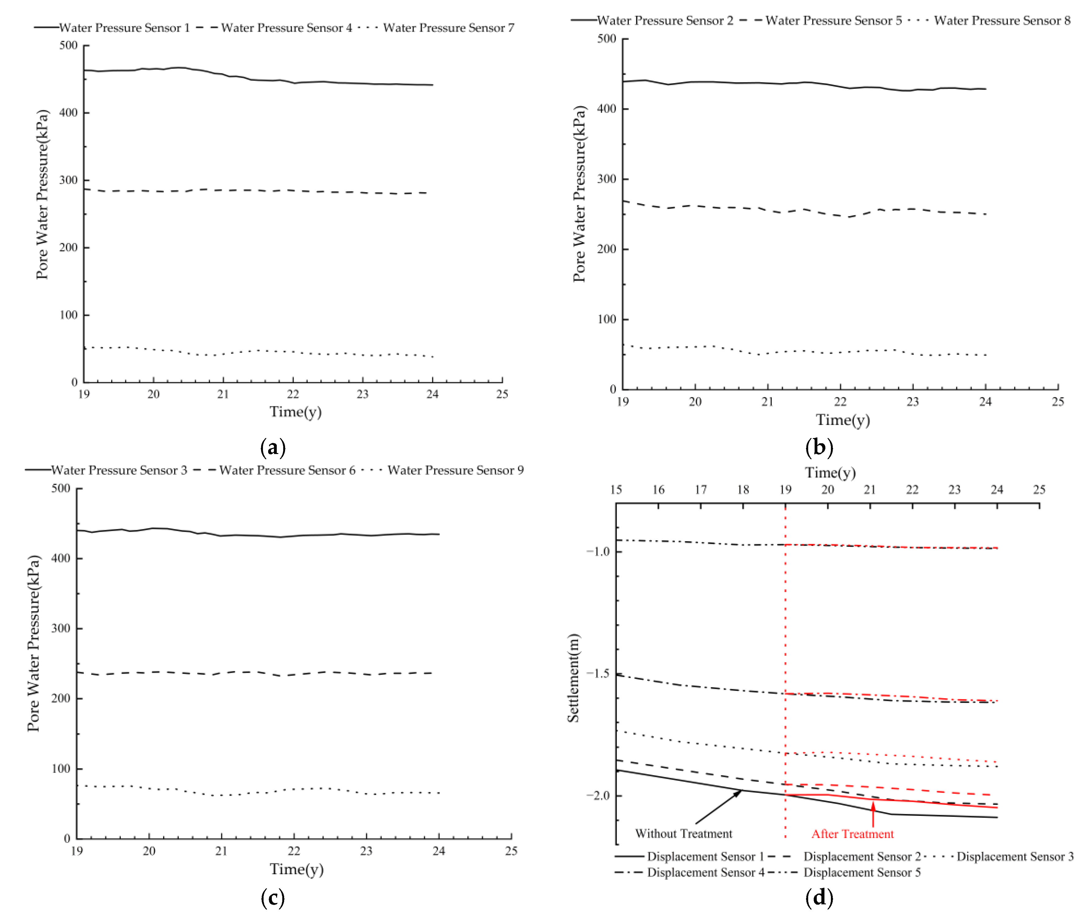
Figure 6.
Diagram of pore water pressure development: (a) below the embankment; (b) below the embankment slope; (c) outside the embankment range and (d) the diagram of settlement without treatment and treated by JGP method.
Figure 6.
Diagram of pore water pressure development: (a) below the embankment; (b) below the embankment slope; (c) outside the embankment range and (d) the diagram of settlement without treatment and treated by JGP method.
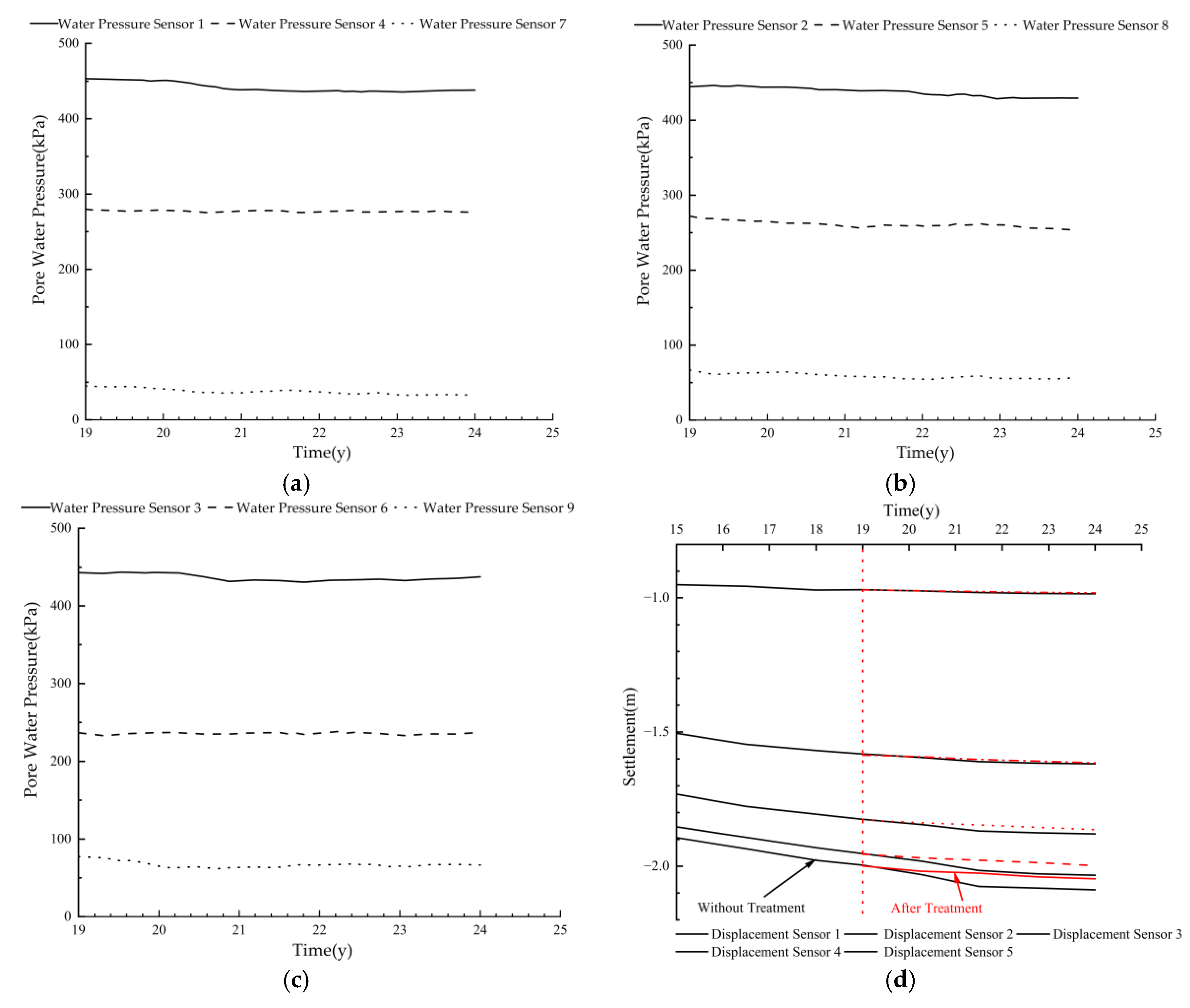
Figure 7.
Diagram of pore water pressure development: (a) below the embankment; (b) below the embankment slope; (c) outside the embankment range and (d) the diagram of settlement without treatment and treated by LDLP method.
Figure 7.
Diagram of pore water pressure development: (a) below the embankment; (b) below the embankment slope; (c) outside the embankment range and (d) the diagram of settlement without treatment and treated by LDLP method.
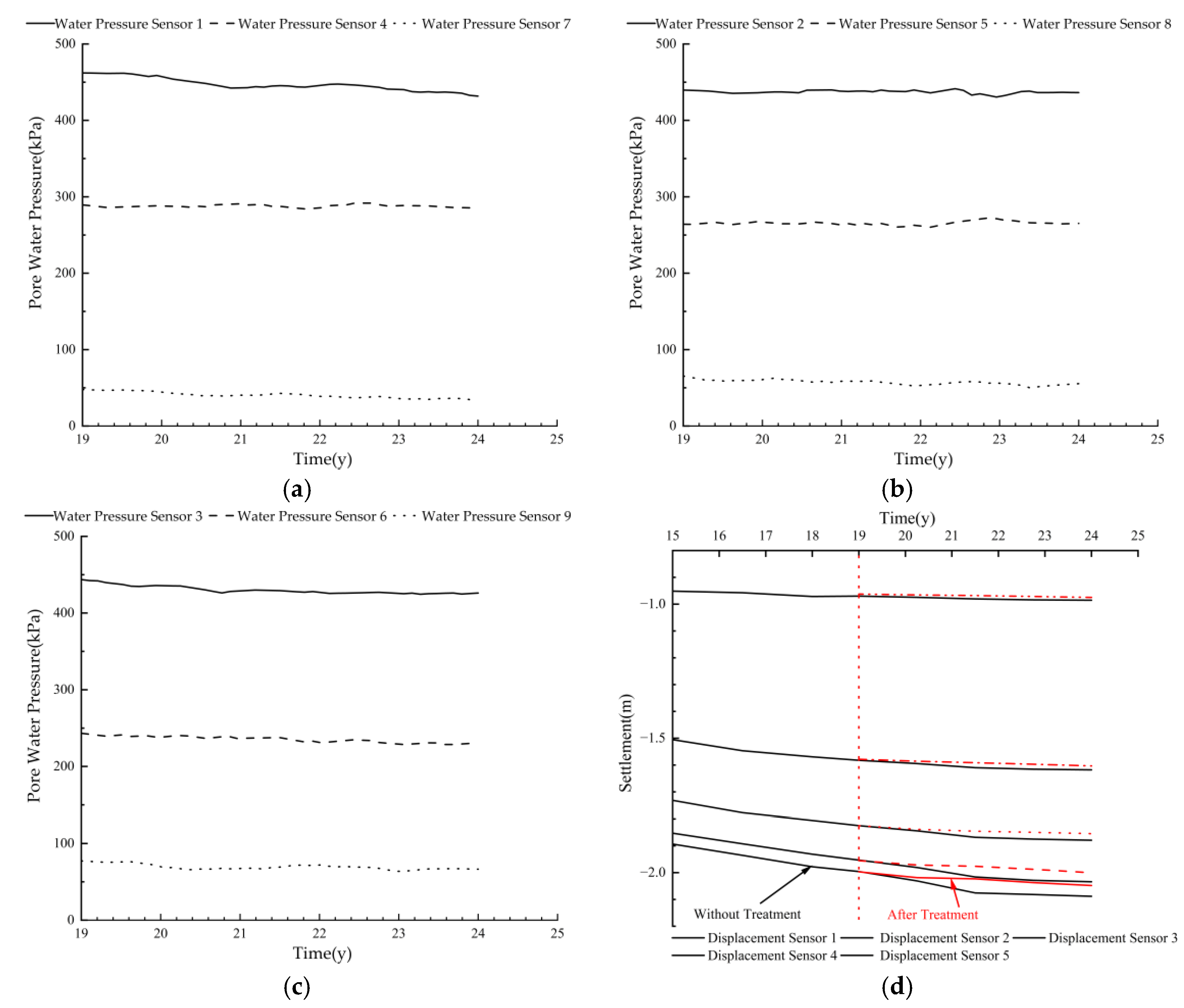
Figure 8.
The developing trend by year of settlement difference between the middle line of embankment and (a) middle line of the half embankment surface; (b) top of the embankment slope; (c) foot of the embankment slope and (d) outside the embankment range.
Figure 8.
The developing trend by year of settlement difference between the middle line of embankment and (a) middle line of the half embankment surface; (b) top of the embankment slope; (c) foot of the embankment slope and (d) outside the embankment range.
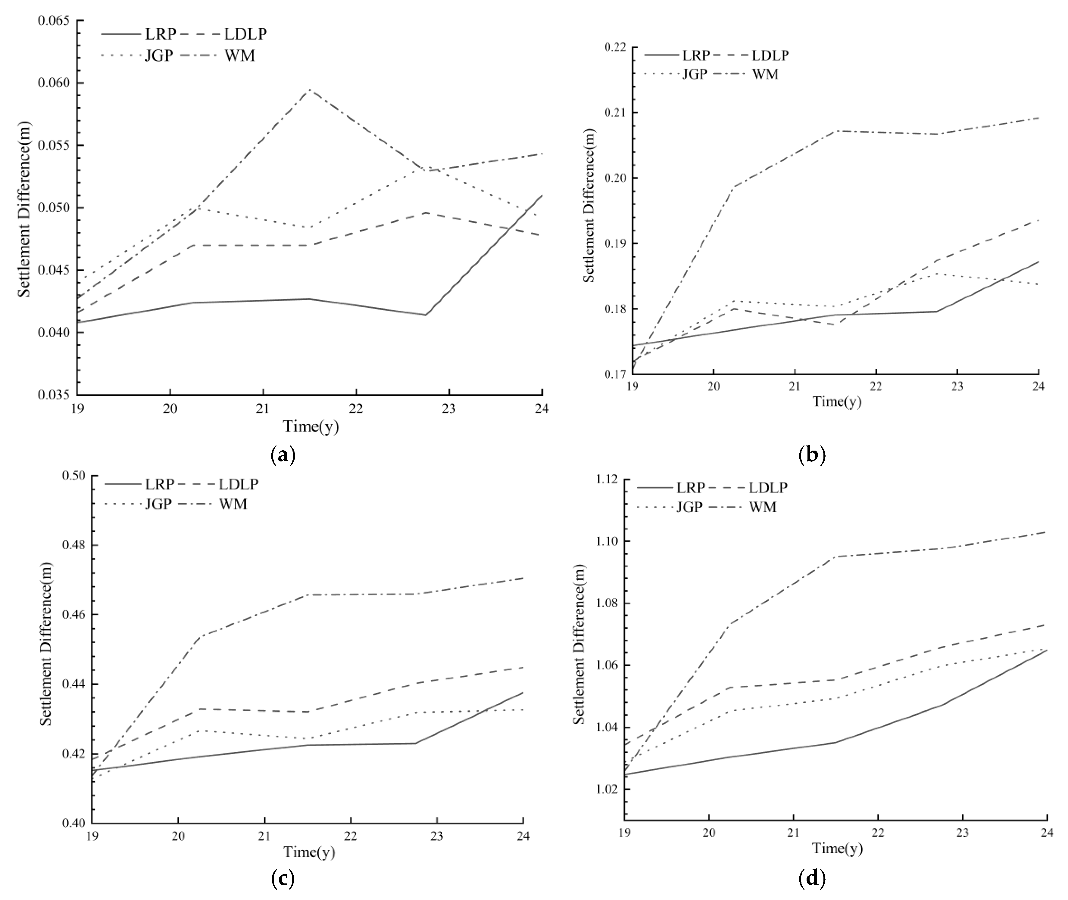
Figure 9.
Settlement reduction compared with control test at the end of the test.
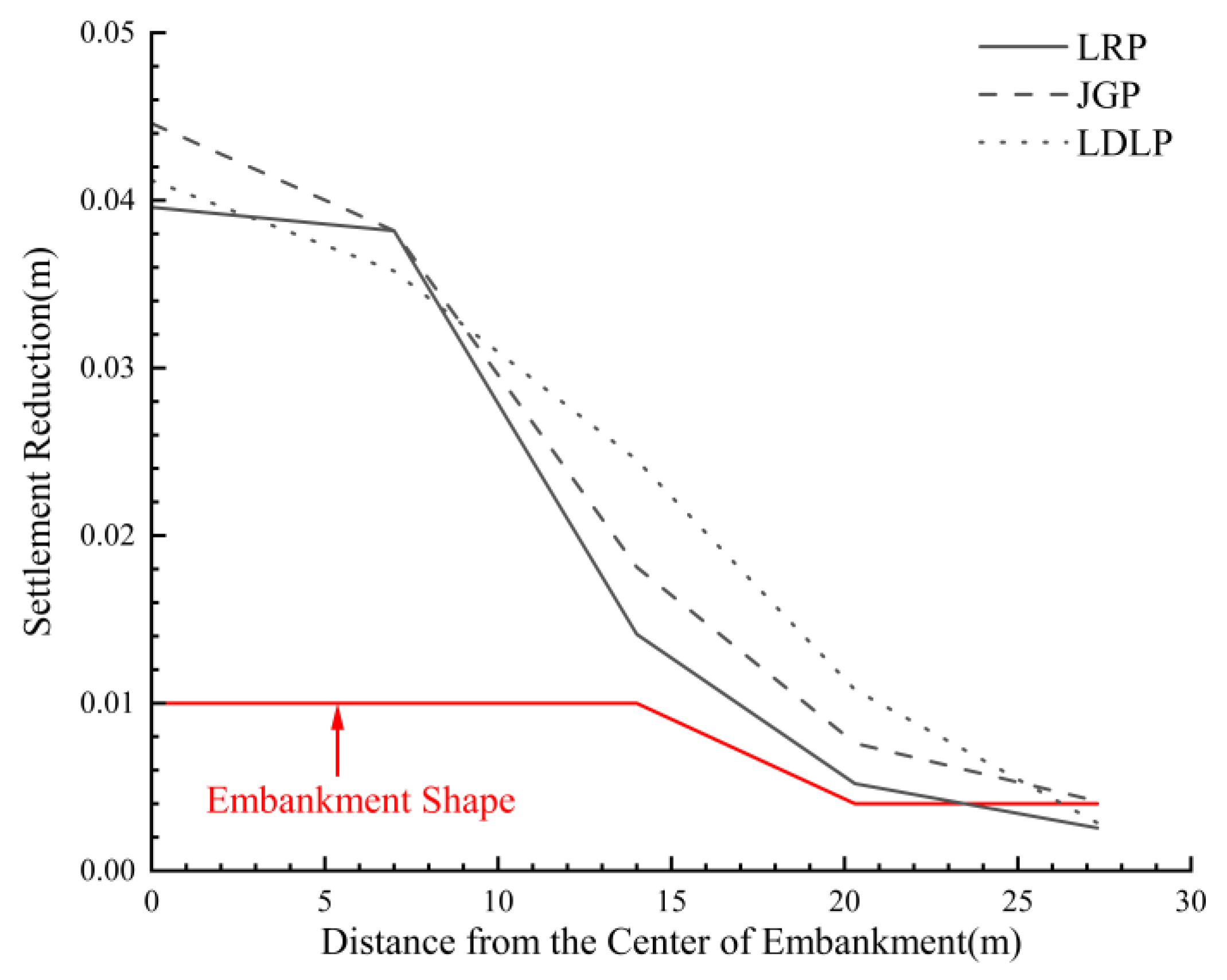
Figure 10.
The bending state of the PVC pipe simulating the LDLP at the end of the test.
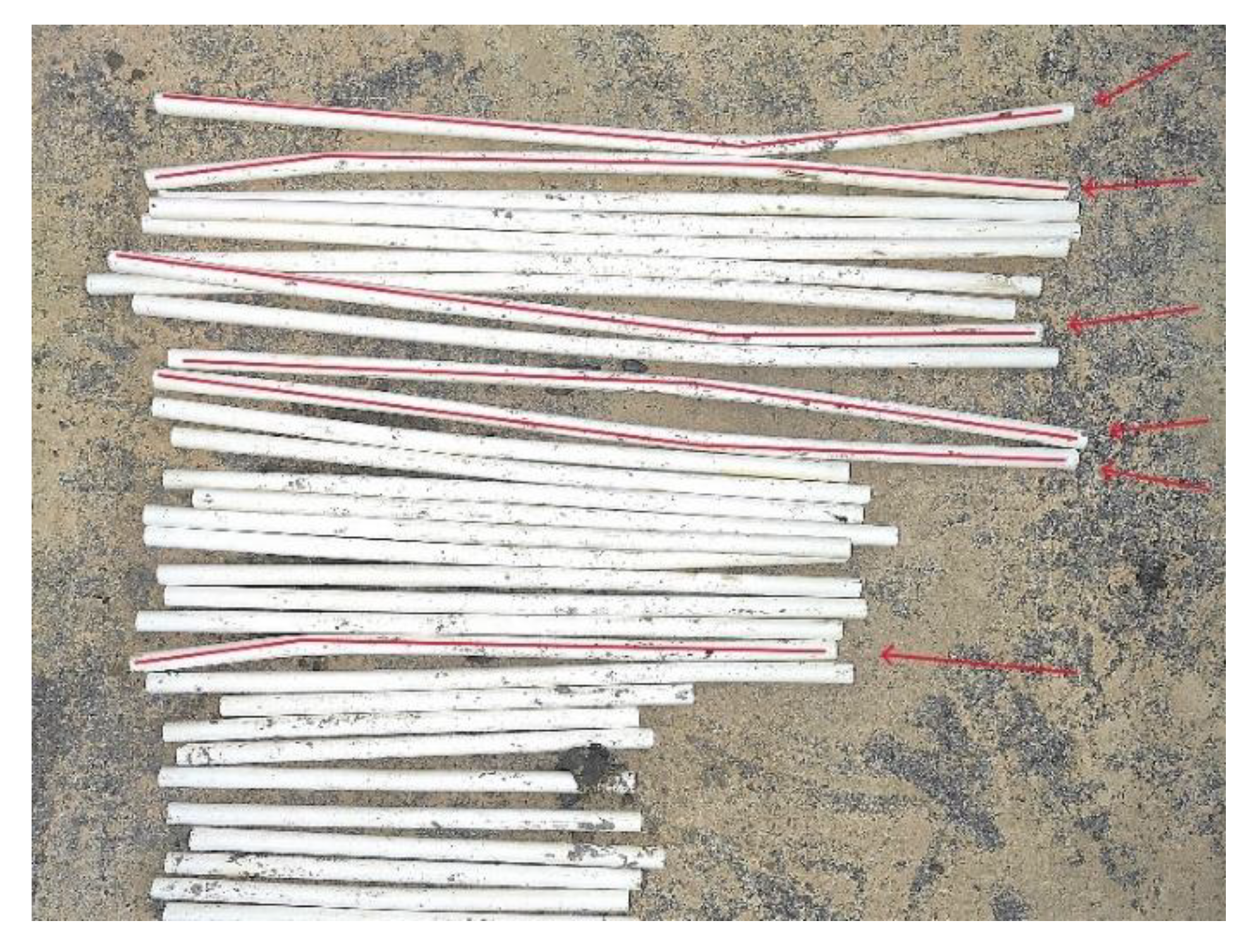

Table 1.
The similarity ratio of the main physical quantities of geotechnical centrifuge model test.
Table 1.
The similarity ratio of the main physical quantities of geotechnical centrifuge model test.
| Physical quantity | Acceleration of gravity g (m/s²) | Displacement s (m) | Geometrical dimension L (m) | Soil density ρ (kg/m3) | Speed v (m/s) | Mass m (kg) |
| Similarity ratio | 70 | 1/70 | 1/70 | 1 | 1 | 1/703 |
| Physical quantity | Moisture content w (%) | Consolidation time t (s) | Permeability coefficient k (cm/s) | Water conservancy i (pa/m) | Stress σ (pa) | Strain ε |
| Similarity ratio | 1 | 1/702 | 70 | 1 | 1 | 1 |
Table 2.
Centrifugal model test scheme.
| Similarity ratio | Model thickness (Embankment + Foundation) (cm)/ Simulated thickness (Embankment + Foundation) (m) | operating mode (h) | Embankment soil quality m (kg) | Foundation soft soil quality m (kg) |
| 70 | 6 + 40 / 4.2 + 28 | 2.5 × (12 + 4) | 13.381 | 162.88 |
Table 3.
Physical and mechanical properties of foundation soft soil.
| Soil layer | Density ρ (g/cm3) | Moisture content w (%) | plastic limit wP (%) | liquid limit wL (%) | initial void ratio e0 | Permeability coefficient k (cm/s) | Thickness d (m) |
| 1 | 1.84 | 35.2 | 24.2 | 46.2 | 1.011 | 5.3×10⁻⁸ | 2 |
| 2 | 1.60 | 66.1 | 26.4 | 53.9 | 1.863 | 1.2×10⁻⁷ | 14 |
| 3 | 1.62 | 62.4 | 28.0 | 56.3 | 1.767 | 1.1×10⁻⁷ | 15 |
| 4 | 1.73 | 45.2 | 26.3 | 51.4 | 1.308 | 1.3×10⁻⁷ | 12 |
| 5 | 1.72 | 48.8 | 26.4 | 51.8 | 1.381 | 1.2×10⁻⁷ | 14.5 |
Table 4.
Settlement of each measuring point.
| year | Settlement of DT1 s1 (m) | Settlement of DT2 s2 (m) | Settlement of DT3 s3 (m) | Settlement of DT4 s4 (m) | Settlement of DT5 s5 (m) |
| 19 | 2.088 | 2.034 | 1.879 | 1.618 | 0.985 |
| 24 | 1.996 | 1.953 | 1.825 | 1.582 | 0.970 |
Table 5.
Cumulative settlement using LRP method and without treatment.
| method | Settlement of DT1 s1 (m) | Settlement of DT2 s2 (m) | Settlement of DT3 s3 (m) | Settlement of DT4 s4 (m) | Settlement of DT5 s5 (m) |
| Control test without treatment | 0.092 | 0.081 | 0.054 | 0.036 | 0.015 |
| Load reducing pipe method test | 0.053 | 0.043 | 0.040 | 0.030 | 0.013 |
| Settlement reduction percentage | 42.3% | 45.7% | 25.9% | 16.7% | 13.3% |
Table 6.
Cumulative settlement using JGP method and without treatment.
| method | Settlement of DT1 s1 (m) | Settlement of DT2 s2 (m) | Settlement of DT3 s3 (m) | Settlement of DT4 s4 (m) | Settlement of DT5 s5 (m) |
| Control test without treatment | 0.092 | 0.081 | 0.054 | 0.036 | 0.015 |
| Jet grouting pipe method test | 0.048 | 0.043 | 0.036 | 0.028 | 0.011 |
| Settlement reduction percentage | 47.8% | 46.9% | 33.3% | 22.2% | 26.7% |
Table 7.
Cumulative settlement using LDLP method and without treatment.
| method | Settlement of DT1 s1 (m) | Settlement of DT2 s2 (m) | Settlement of DT3 s3 (m) | Settlement of DT4 s4 (m) | Settlement of DT5 s5 (m) |
| Control test without treatment | 0.092 | 0.081 | 0.054 | 0.036 | 0.015 |
| lateral displacement limiting pile method | 0.051 | 0.045 | 0.030 | 0.025 | 0.013 |
| Settlement reduction percentage | 44.6% | 44.4% | 44.4% | 25.0% | 13.3% |
Table 8.
Average falling rates of pore water pressure in each measuring point in 5 years.
| Measuring Points |
Average reduction rates of pore water pressure (%) | ||||||||
|---|---|---|---|---|---|---|---|---|---|
| WP1 | WP2 | WP3 | WP4 | WP5 | WP6 | WP7 | WP8 | WP9 | |
| WT | 4.080 | 2.414 | 1.643 | -0.015 | 3.887 | 2.041 | 5.380 | 4.122 | 3.232 |
| LRP | 4.198 | 2.228 | 0.899 | 0.940 | 3.205 | 0.101 | 2.546 | 2.539 | 1.992 |
| JGP | 3.027 | 3.153 | 1.165 | 0.607 | 3.271 | -0.199 | 2.346 | 1.736 | 1.991 |
| LDLP | 5.708 | 0.553 | 3.432 | 0.540 | -0.129 | 2.401 | 2.480 | 1.739 | 1.992 |
Disclaimer/Publisher’s Note: The statements, opinions and data contained in all publications are solely those of the individual author(s) and contributor(s) and not of MDPI and/or the editor(s). MDPI and/or the editor(s) disclaim responsibility for any injury to people or property resulting from any ideas, methods, instructions or products referred to in the content. |
© 2025 by the authors. Licensee MDPI, Basel, Switzerland. This article is an open access article distributed under the terms and conditions of the Creative Commons Attribution (CC BY) license (http://creativecommons.org/licenses/by/4.0/).
Copyright: This open access article is published under a Creative Commons CC BY 4.0 license, which permit the free download, distribution, and reuse, provided that the author and preprint are cited in any reuse.


