1. Introduction
Double-acting vane pumps are widely used in various industrial and automotive applications due to their compact design, high efficiency, and ability to deliver consistent flow rates under varying operating conditions. A key element that governs the performance and durability of these pumps is the interaction at the contact surface between the vanes and the stator. This interaction plays a key role in ensuring effective sealing, minimizing leakage, and maintaining smooth operation throughout the life of the pump.
However, the contact interface is subject to complex mechanical and tribological phenomena, including high pressure fluctuations, varying loads, and lubrication challenges. The contact dynamics significantly affect wear rates, energy losses, and overall pump efficiency. In addition, the complex interaction between blade material properties, stator surface characteristics, and lubricant film behavior further complicates the analysis and optimization of this critical interface.
The findings of this research will not only contribute to the fundamental understanding of the operation of vane pumps, but will also provide information on the design of more efficient and durable pumping systems for demanding applications.
A double-acting vane pump performs two pumping cycles per rotor revolution due to its symmetrical design. These phases occur simultaneously on opposite sides of the rotor.
The suction phase occurs when the rotor rotates and the vanes slide outward along the stator profile due to centrifugal force and fluid pressure. The increased volume between adjacent vanes on one side of the rotor creates a vacuum, drawing fluid into the pump through the inlet port. This occurs at the widest part of the stator profile.
The compression phase occurs after the suction as the rotor and vanes continue to rotate towards the narrower part of the stator. The fluid-filled chamber decreases in size as the vanes are pulled inward, compressing the fluid. The discharge phase occurs when the compressed fluid is expelled through the outlet when the chamber volume reaches its minimum. This discharge process is synchronized with the compression phase on the opposite side of the rotor.The compression phase occurs after the suction as the rotor and vanes continue to rotate towards the narrower part of the stator. The fluid-filled chamber decreases in size as the vanes are pulled inward, compressing the fluid. The discharge phase occurs when the compressed fluid is expelled through the outlet when the chamber volume reaches its minimum. This discharge process is synchronized with the compression phase on the opposite side of the rotor.
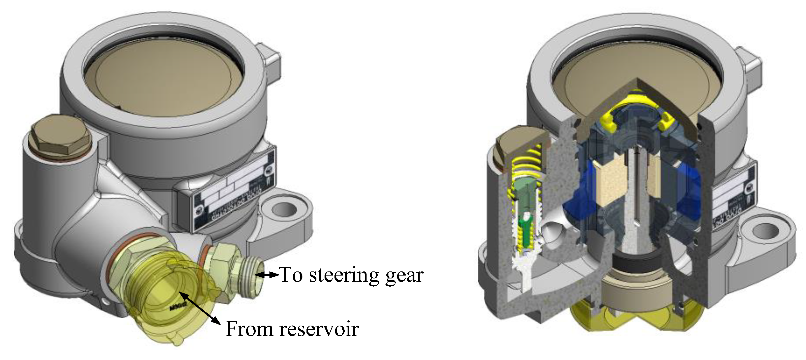
Figure 1.
Model of vane pump with double effect and section cut of pump.
Figure 1.
Model of vane pump with double effect and section cut of pump.
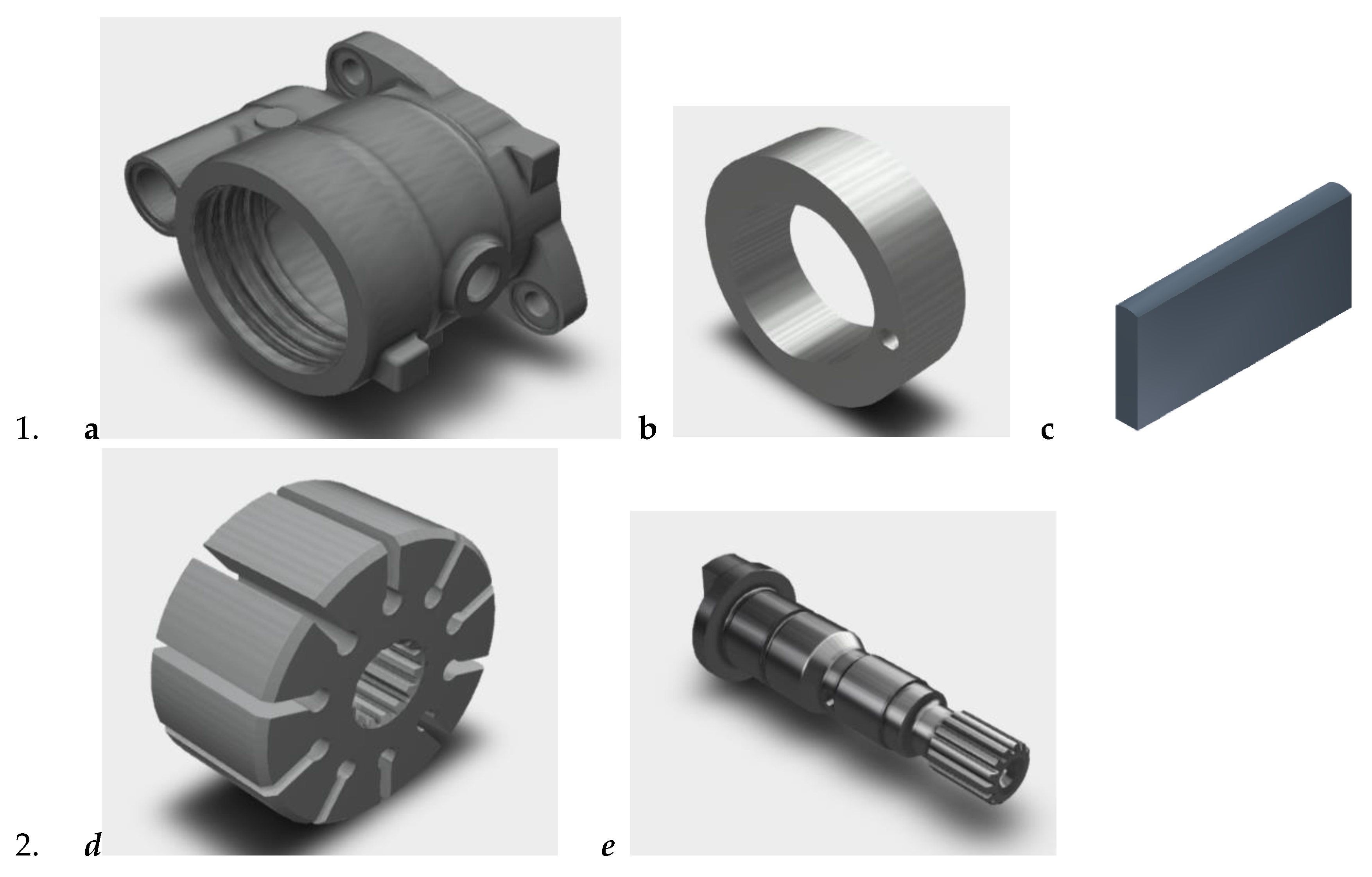
The main parts of a double-acting vane pump are shown in
Figure 2, and their role is as follows:
The pump housing (
Figure 2a) has an inlet and outlet port. The ports in the pump housing for the inlet (suction) and outlet (discharge) of the fluid are usually located diametrically opposite for double-acting function). The pump housing includes the rotor, stator, vanes and other components and ensures the integrity of the structure and the content of the working fluid.
The stator (
Figure 2b) is fixed to the outer casing, with an elliptical or eccentric internal profile, guides the vanes and provides a sealing surface during operation.
The vanes (
Figure 2c) are rectangular in shape, radially inserted into the slots of the rotor and are in contact with the stator under the action of centrifugal force or spring force.
The rotor (
Figure 2d) is a rotating element mounted eccentrically within the pump housing, containing radial slots for accommodating the vanes and driving the blades to follow the contours of the stator.
The drive shaft (
Figure 2e), receives mechanical energy from the pump drive motor.
The seals and bearings prevent fluid leakage, support the rotor during operation, and increase durability and reduce
The double-acting design provides simultaneous action so that while suction occurs on one side of the rotor, discharge occurs on the other. This continuous operation results in smoother flow and reduced pulsation compared to single-acting pumps. The double-acting mechanism increases volumetric efficiency by allowing two fluid delivery cycles per rotation. Reduced pulsation ensures a stable flow, critical for hydraulic and automotive applications.
2. Mathematical Model
Based on the load calculations, a mathematical model was derived that describes the physical processes in the sliding gap between the vane and the lifting ring. Due to the high contact loads, the rules of elastohydrodynamics were applied. The complete contact model was modified to solve the specific problem of calculating the sliding gap in the vane pump.
An approach has been developed in which the pressure and gap profile in a sliding contact are determined using approximate equations and the accurate calculation of the velocity, temperature, and viscous field in the gap is specified. With a simulation program created based on this approach, the gap parameters can be calculated by varying the external contact loads, geometry, and fluid properties.
2.1. Model Assumptions
The blades are considered rigid, and the deformation is primarily attributed to the stator surface or the lubricant film.
Lubrication at the blade-stator interface follows a hydrodynamic or mixed lubrication regime.
Friction and wear are modeled using Coulomb friction and Archard's wear law, respectively.
The fluid dynamics in the blade chamber are governed by the Reynolds equation and conservation of mass.
2.2. Volumetric Losses Affecting Pressure Changes
To operate properly, the pump must have adequate clearances between the rotor blades and the valve plates. There is a certain flow through these clearances. Volumetric losses in the chamber can be classified as follows:
losses at vane side made by axial clearances Van
losses over vane top made by radial clearances Vrn
losses made by flow withdrawal Vpr
losses through the slot at valve plate Vpz
losses through the gap made by the vane in rotor groove Vpc
2.2.1. Losses Made by Axial Clearances
Assuming that the flow is current, the losses through the axial clearances are:
- a)
volumetric losses for the chamber in front of the vane:
- b)
volumetric losses for the chamber behind the vane :
2.2.2. Losses Made by Radial Clearances
Between the inside surface of the stator and vane top working flow leaks which can be presented as :
- a)
volumetric losses for the chamber in front of the vane can be presented :
- b)
volumetric losses for the chamber behind the vane can be presented :
2.2.3. Losses Made by Flow Withdrawal
The mean value of lossess made by flow withdrawal at the vane is presented by :
2.2.4. Losses Through the Slot at Valve Plates
Losses through the slot in thrust port at valve plate are determined in the following manner:
2.2.5. Losses Made by the Vane in Rotor Groove
If the pressure in the chamber is higher than working pressure of the pump there is a gap in rotor groove made by front vane tilting because of tangential load and there is oil leakage which can be presented by:
2.3. Rate of Change of Pressure in the Chamber
If initial volume V is lowered for
due to pressure rise
the relative volume
, calculated per pressure unit:
is compressibility coefficient. The reciprocating value of compressibility coefficient is called the compressibility modulus (
),
which has the same dimension as the pressure.
In previous expressions the minus sign shows that pressure rise corresponds to volume decrease and vice versa. The previous expression can be also presented in the following form, in case of final changes of pressure and volume
which represents so called Hooke's law.
The pressure increment in the working chamber of vane pump with double effect can be reached from the following expression (10)
Volume
is calculated like this:
The speed of pressure change in the chamber is obtained by differentiating the expression (11) in case when
If we put the expressions for volumetric losses (1 to 7) into the expression for speed of pressure change in the chamber (14) we reach the following expression:
After replacing the values for volumetric losses we get required expression for speed of pressure change in relation to the clearance in the chamber of vane pump with double effect:
3. Simulation Results
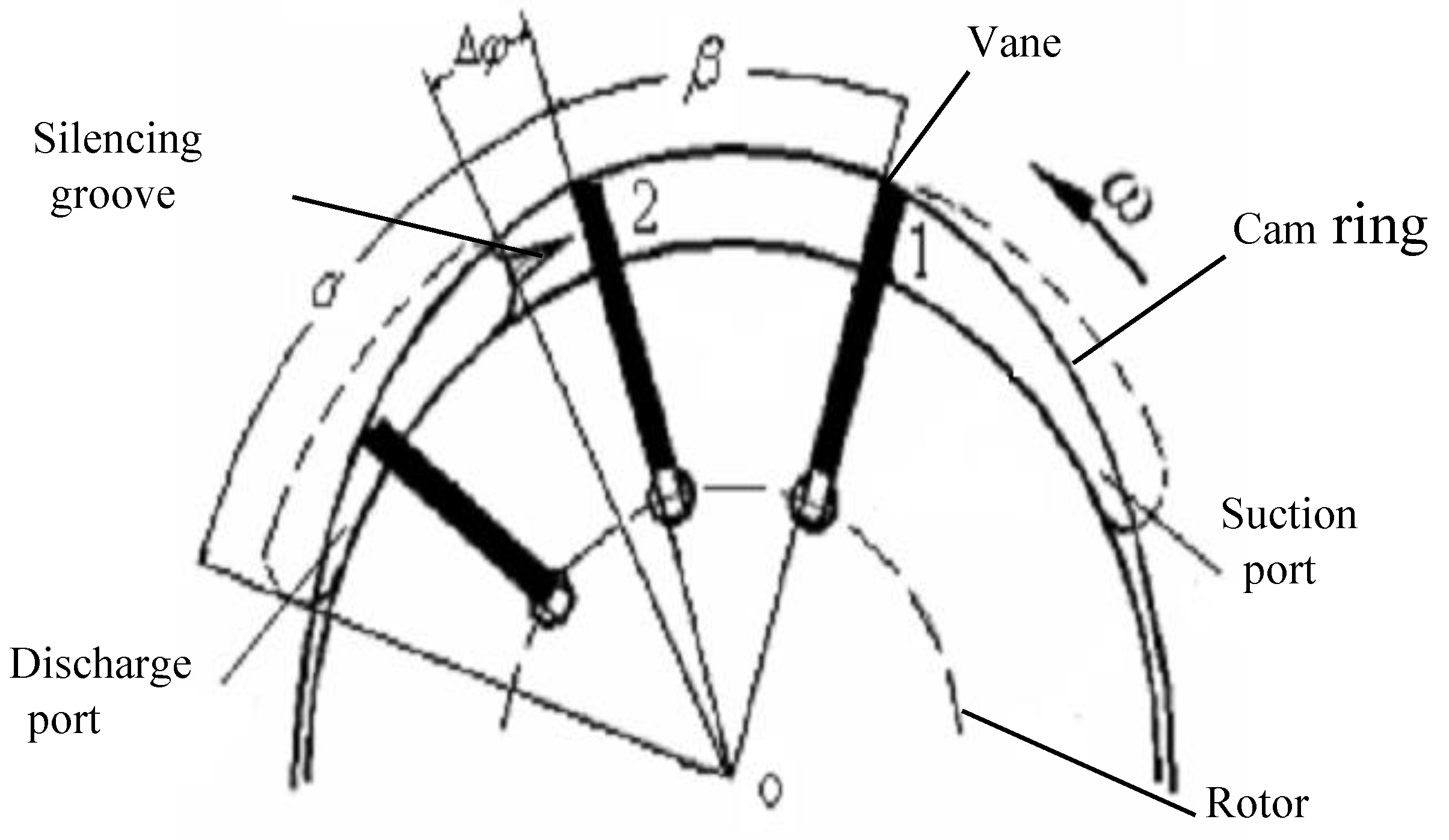
Figure 3 shows the general configuration of a vane pump. The pump consists of several vanes within a rotor. The vanes are nested in a circular array within the rotor at equal intervals. The vanes are held tightly against a ring using the force of fluid and the centrifugal force, and the bushing is held tightly against the rotor and ring. While the rotor isdriven, a single chamber consists of neighboring vanes and rotorring and bushings.
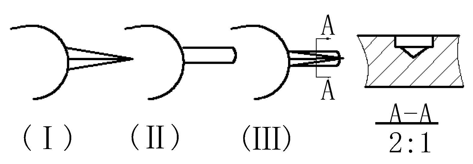
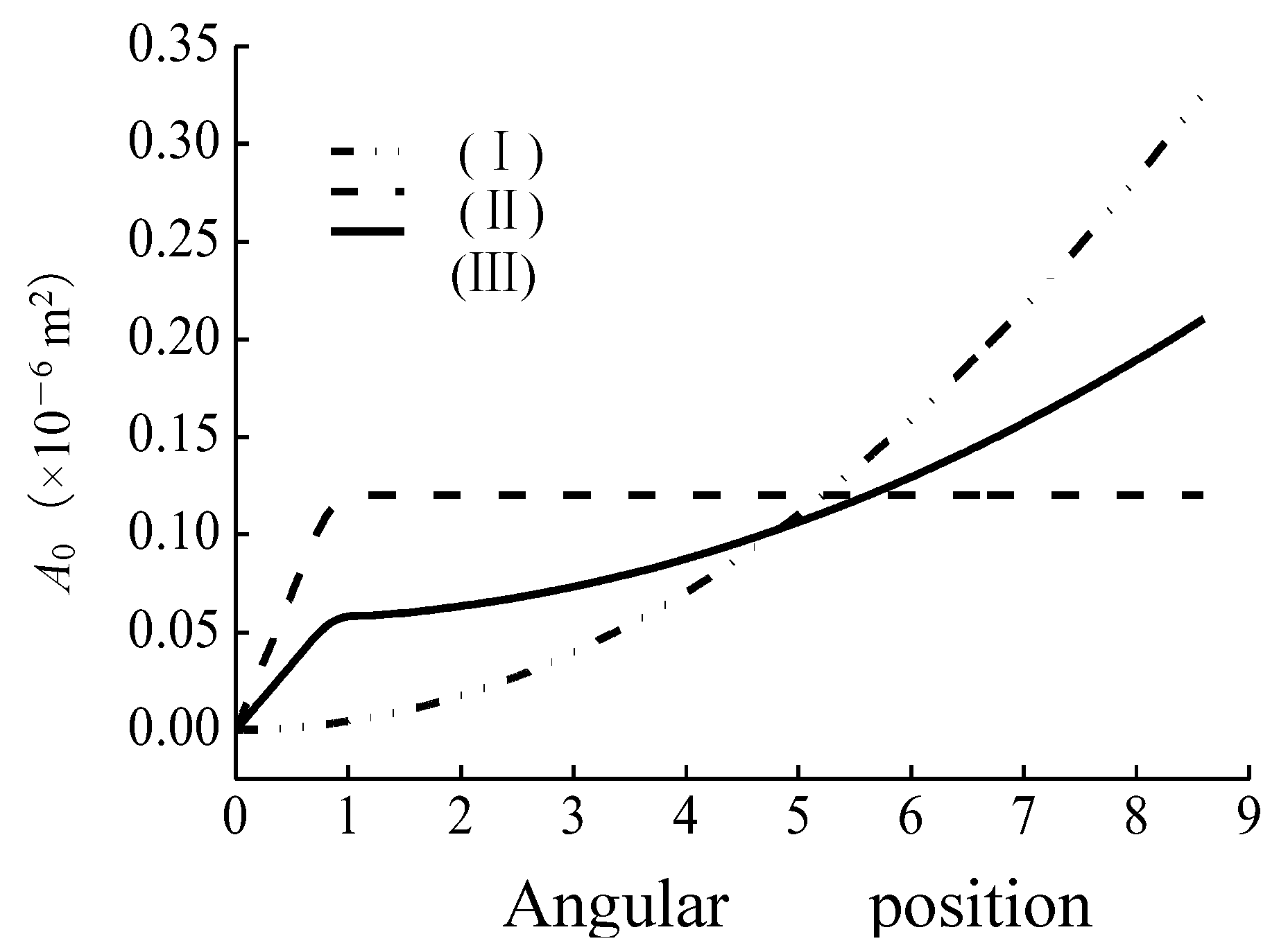
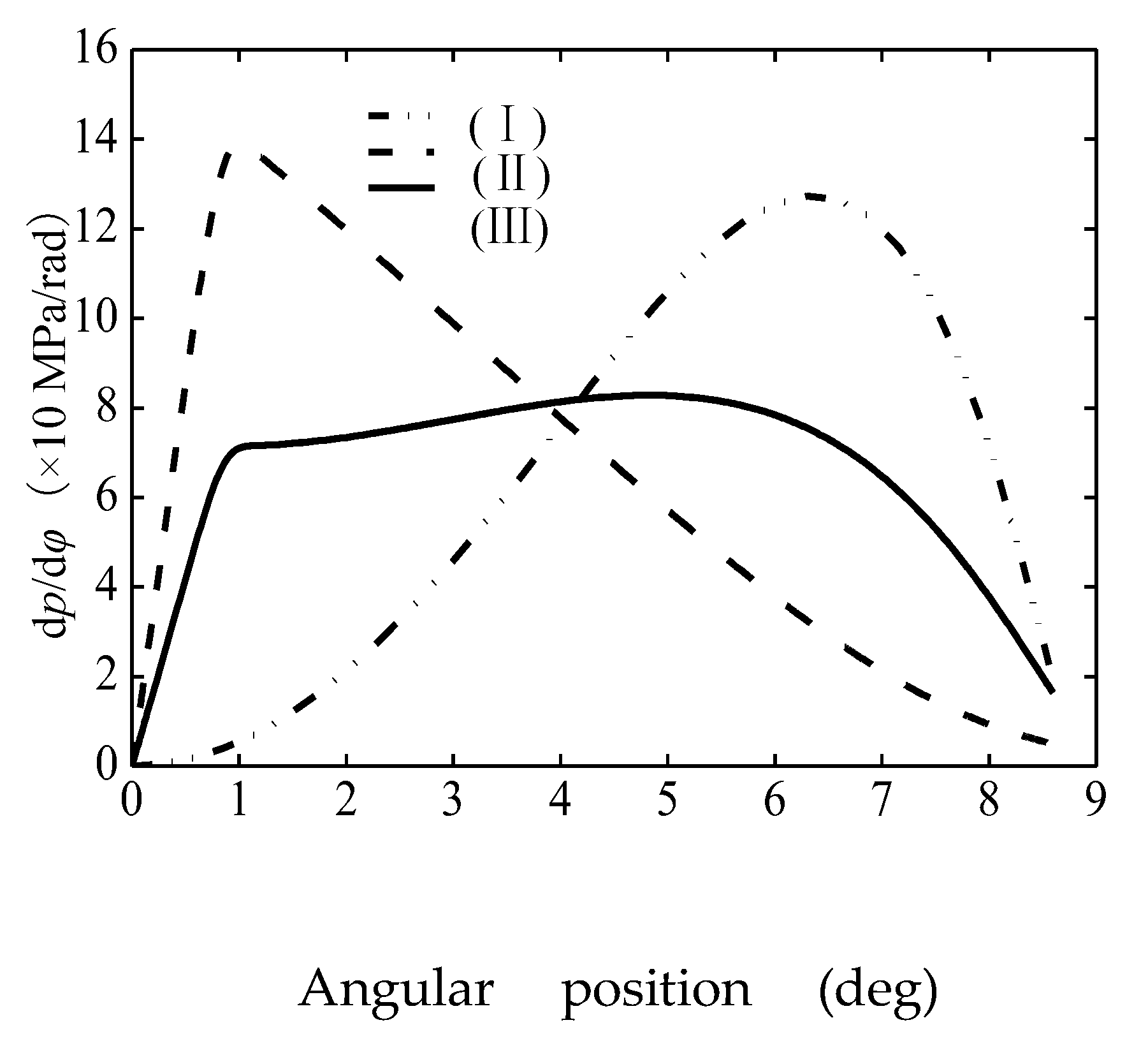
Figure 4 shows the configuration of variable are asilencing groove (Ⅰ) and invariable area silencing groove (Ⅱ) and complex silencing grooves (Ⅲ) which are used on the bushing. The section of variable area silencing groove and invariable area silencing groove are corresponding triangle and rectangle.
The complex silencing grooves are parallel connection of triangle and rectangle. In this paper, the calculation of three type silencing grooves area follow the principle that the backfilling volume of oil through silencing grooves are same within the angle of transition regions (
Δφ).
Figure 5 shows the area of three type silencing grooves as
φ goes from
0 to
Δφ.
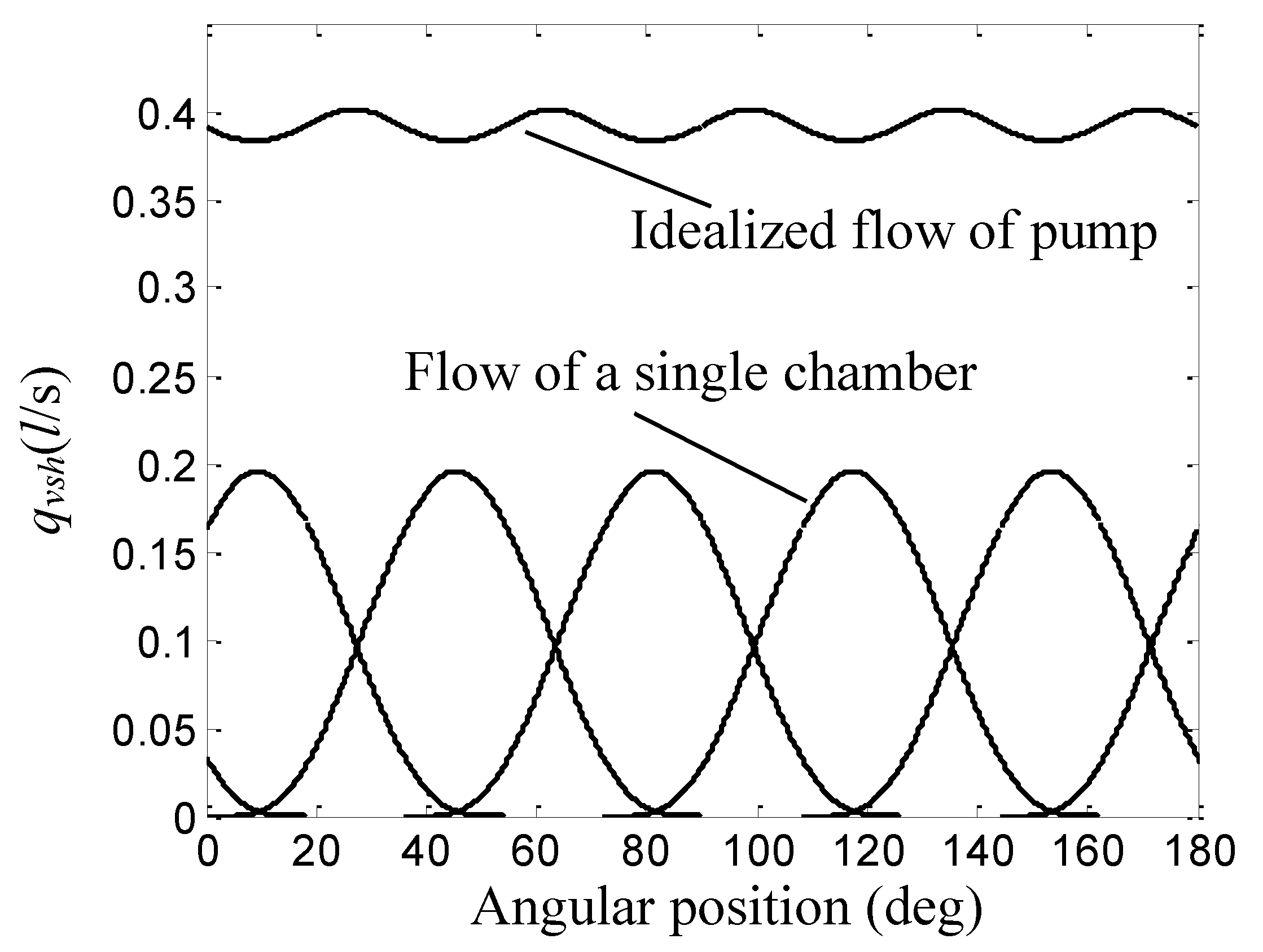
Figure 6 illustrates the shape of idealized pump flow as it varies with
φ. From the results which are shown in
Figure 6, it can be conclude that the vanes which pass over the intake ports withdrawing from the rotor is the only influential factors of idealized flow-ripple.
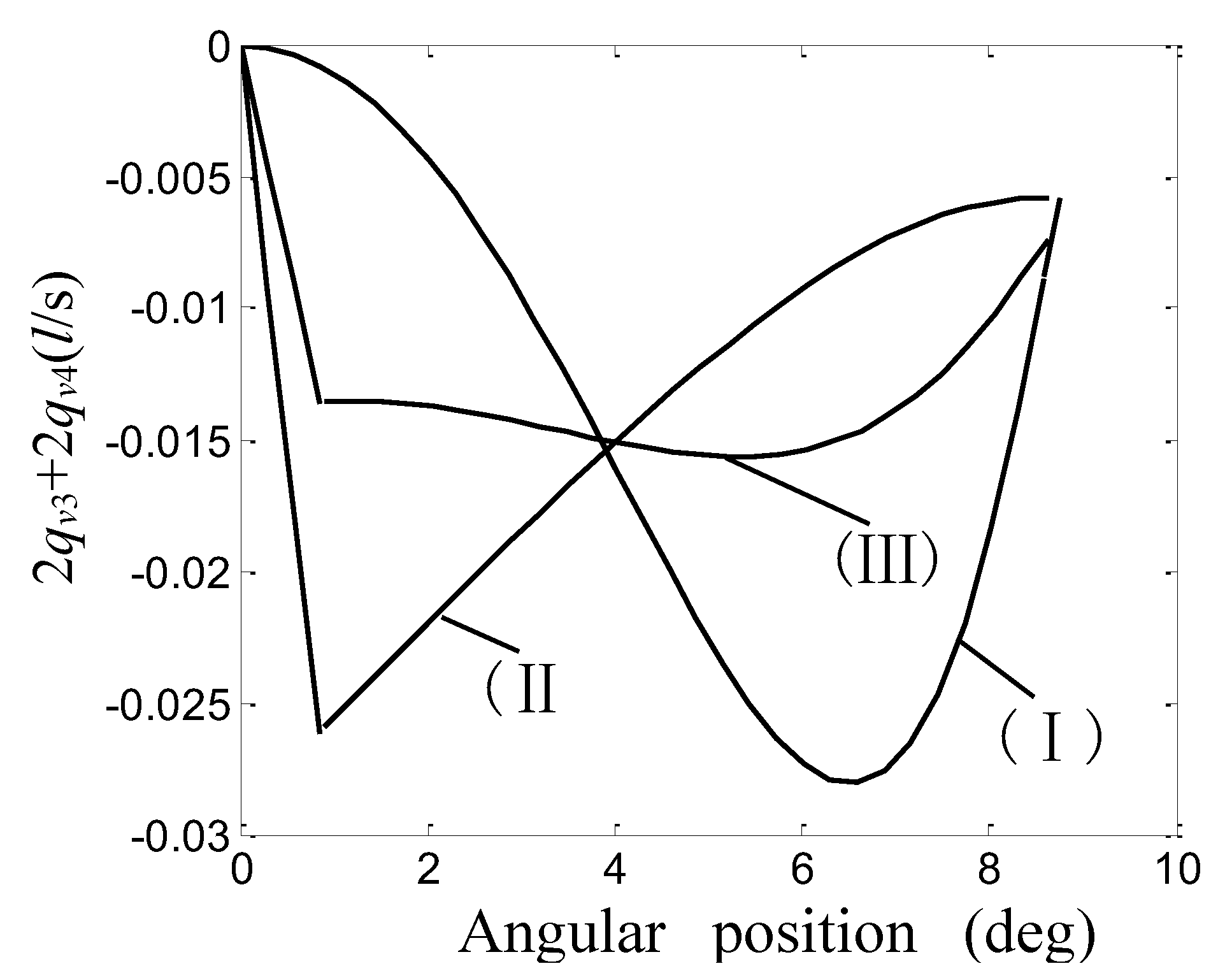
Figure 7 illustrates the shapes of back filling flow under the adoption of three type silencing grooves as it varies with
φ. From the results, one may generally conclude that the Max. Of negative flow is only half at the adoption of complex silencing grooves compare with the separateness adoption of variable area silencing groove or invariable area silencing groove.
Substituting the numerical results of
pinto can yield the pressure gradient
dp/dφ vary with the configuration of silencing groove, as shown in
Figure 8.
x
4. Experimental Verification
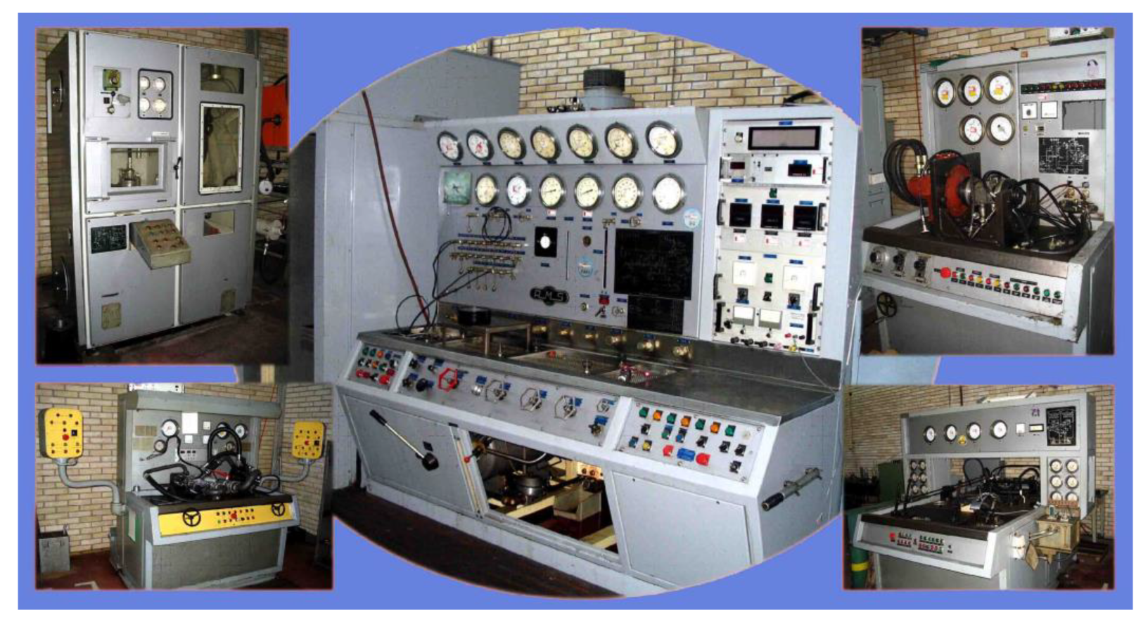
Experimental verification of the operating parameters of the prototype of the double-acting vane pump type 641-4300L, with simulation of real pump operating conditions, was carried out on a multi-purpose hydraulic test bench AMS ZI 108-94262 FRESNES (FRANCE) TYPE BAH 1622/B38-5.
This multi-purpose hydraulic test bench is used for testing pumps, hydraulic motors (hydraulic motors), manifolds, other hydraulic accessories (cranes, valves, etc.) and assemblies and static testing of hydraulic components. The equipment consists of three sub-assemblies: test panel, hydraulic system and electrical cabinet.
The hydraulic system is installed in a separate room. The electrical system is in the same room as the hydraulic system and groups. All necessary electrical components work on the stand.
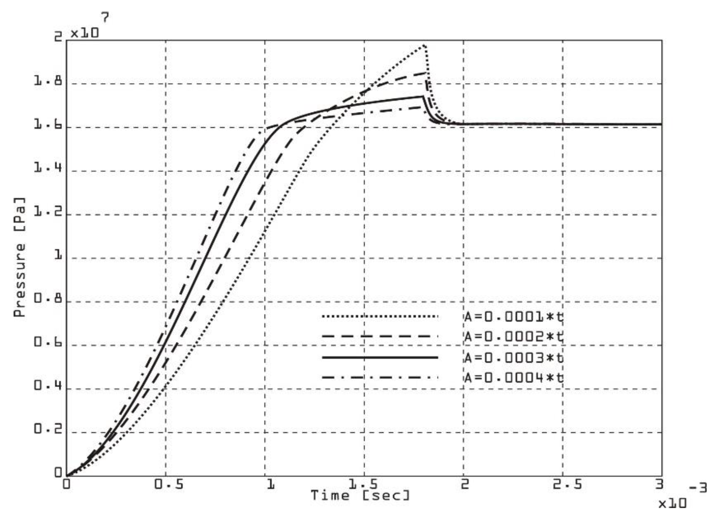
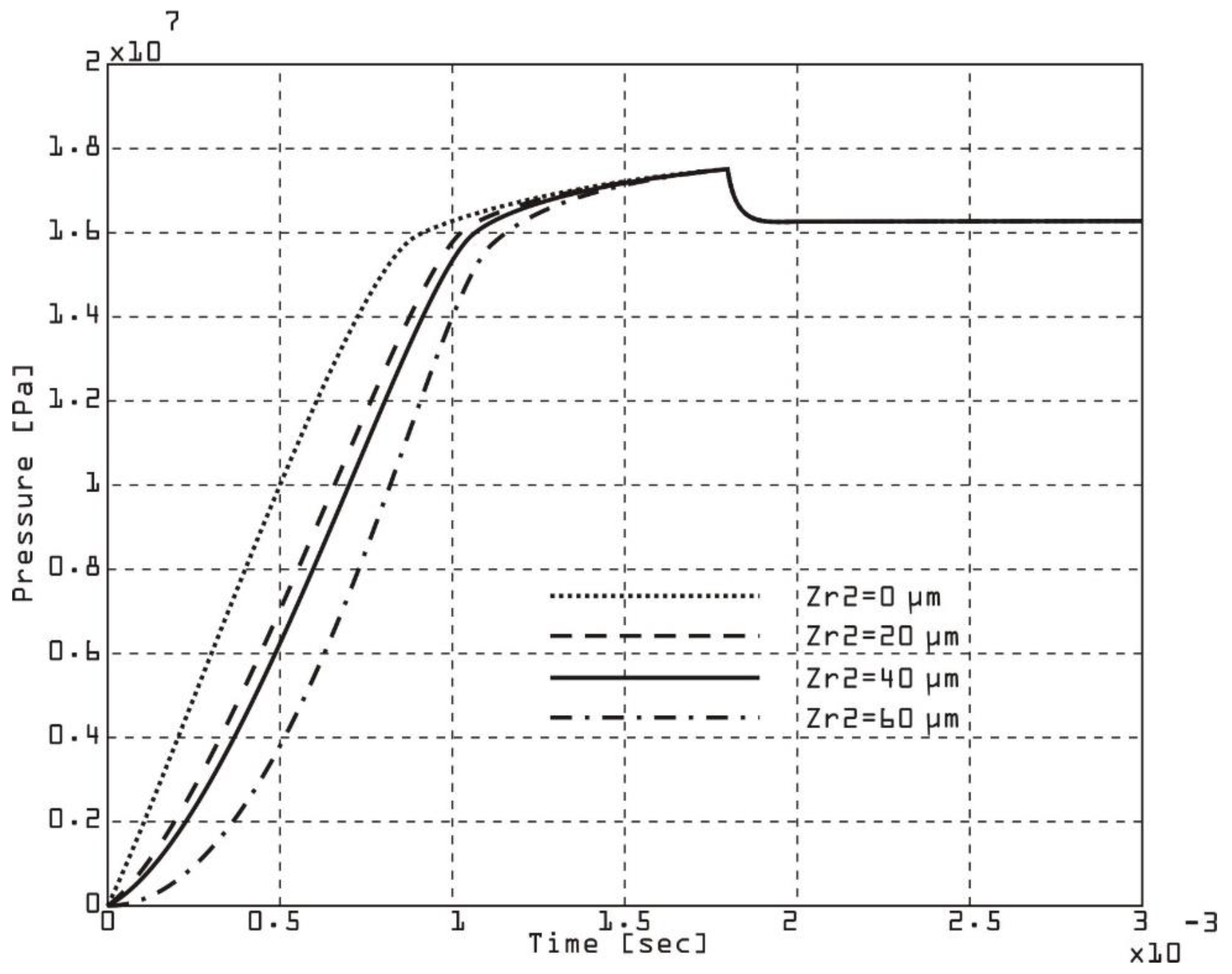
The rate of pressure change in a double-acting vane pump chamber can be affected by axial clearance (
Figure 10 and
Figure 11) due to its effect on internal leakage and compression/expansion dynamics. Larger axial clearances result in larger leakage, reducing the effective pressure increase. The positioning and contact of the first vane with the chamber wall affect the rate of pressure change. The viscosity and density of the fluid will determine how the leakage flow will behave through the axial clearance. High rotational speeds reduce leakage time, but increase dynamic effects. A smaller clearance reduces leakage flow, resulting in a larger pressure change and better efficiency. A larger clearance increases leakage, resulting in a slower pressure change and potential pressure instability.
The simulation results were validated with experimental data by measuring chamber pressures at different operating conditions and axial clearances.
The rate of change of chamber pressure for different values of axial clearance on the first vane of a double-acting vane pump is shown in
Figure 10.
The rate of change of chamber pressure due to variations in axial clearance on the second vane
Figure 11 of a double-acting vane pump can be determined using a similar approach to the first vane, but taking into account how the second vane affects the pressure dynamics within its chamber.
The second vane operates in a different phase of the pump cycle (e.g. expansion or compression), which means that its influence on the pressure dynamics may differ from that of the first vane.
The axial clearance on the second vane affects internal leakage, which directly affects the pressure rise or fall in the chamber associated with this vane.
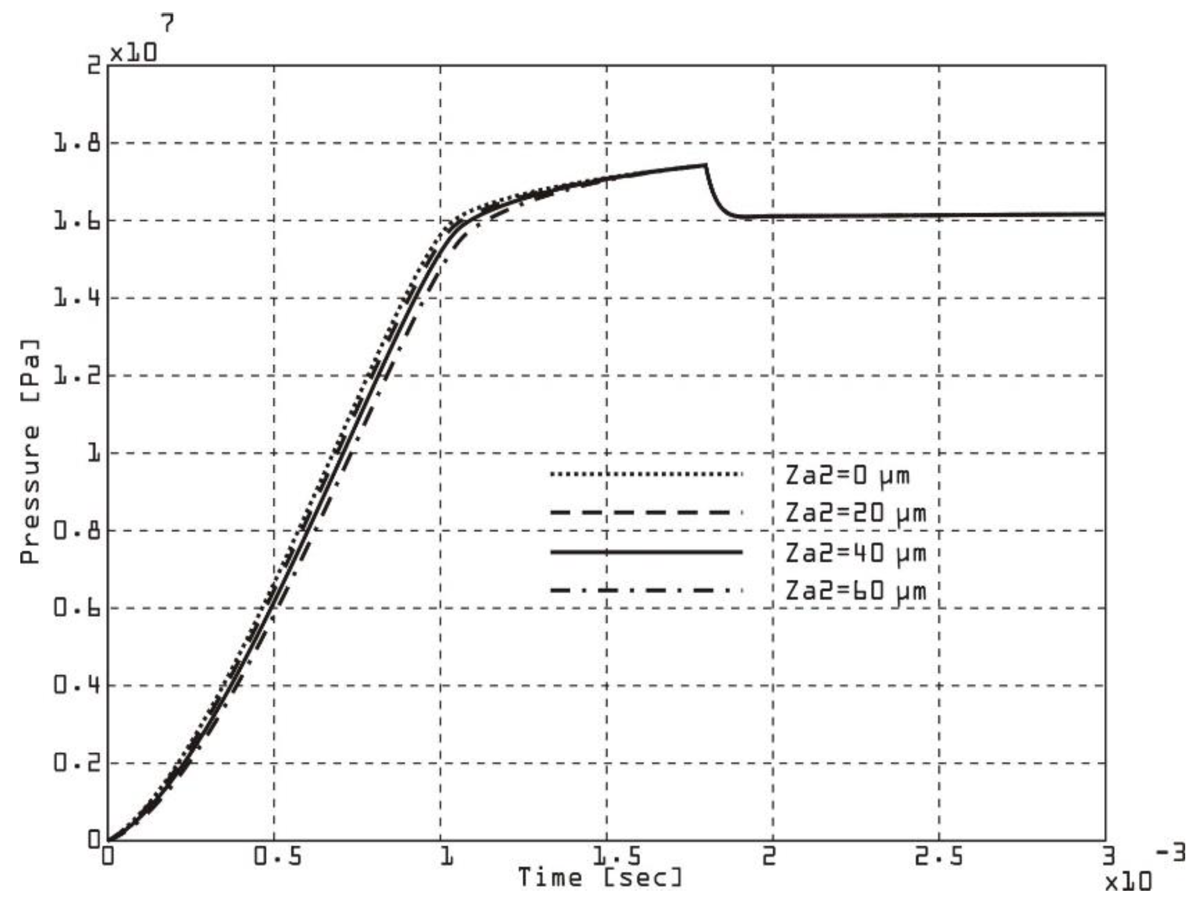
The rate of change of pressure in the chamber of a double-acting vane pump for different radial clearances (
Figure 12 and
Figure 13) can be analyzed by considering how the radial clearance affects leakage, vane dynamics, and the compression/expansion processes in the chamber. The radial clearance refers to the distance between the vane tip and the inner surface of the pump stator. This directly affects the leakage flow. Larger clearances allow more fluid to leak past the vane tip. Vane dynamics affect irregular contact, and large clearances can result in ineffective chamber sealing. Smaller radial clearances improve sealing and increase pressure rise rates. A small clearance minimizes leakage flow, provides a better chamber seal, and results in a higher rate of pressure change. Large clearance increases leakage flow, reducing the effective pressure increase, slowing the rate of pressure rise, and reducing volumetric efficiency. It can cause instability or uneven pressure profiles. By instrumenting the vane pump with pressure sensors near the first vane chamber, the chamber pressure was measured over time for various radial clearance conditions. Comparing the experimental data with the simulation results, the expected trends were obtained. A smaller radial clearance gives steeper and more consistent pressure rise curves, while a larger radial clearance gives shallower pressure rise curves with potential delays in reaching peak pressure.
The rate of change of pressure in the chamber of a double-acting vane pump when the radial clearance on the second vane is changed (
Figure 13) is critical to understanding its impact on leakage, sealing, and efficiency. The dynamics of the second vane are particularly important because they affect the pressure dynamics in the corresponding chamber during specific phases of the pump cycle (e.g. compression or expansion)
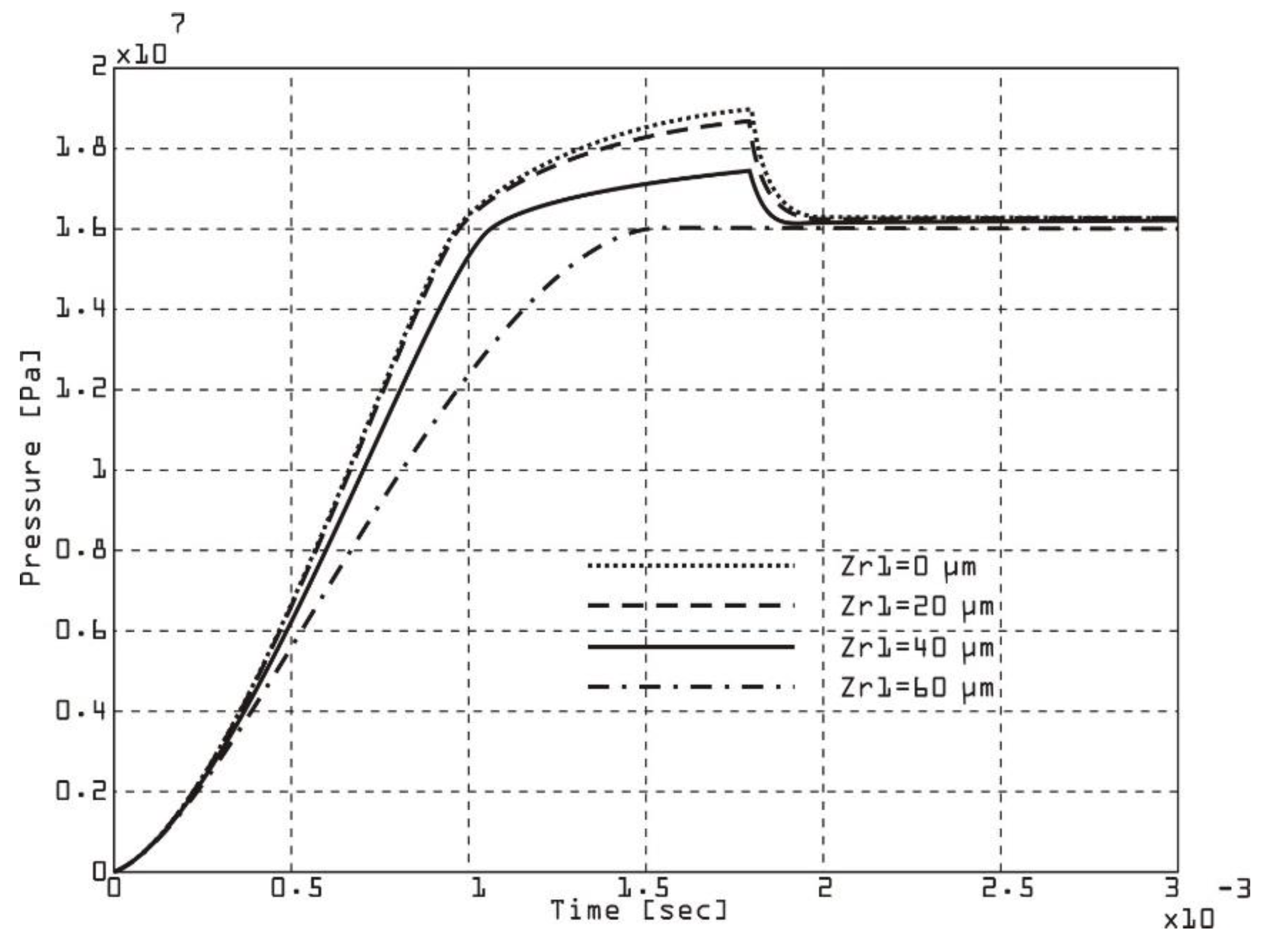
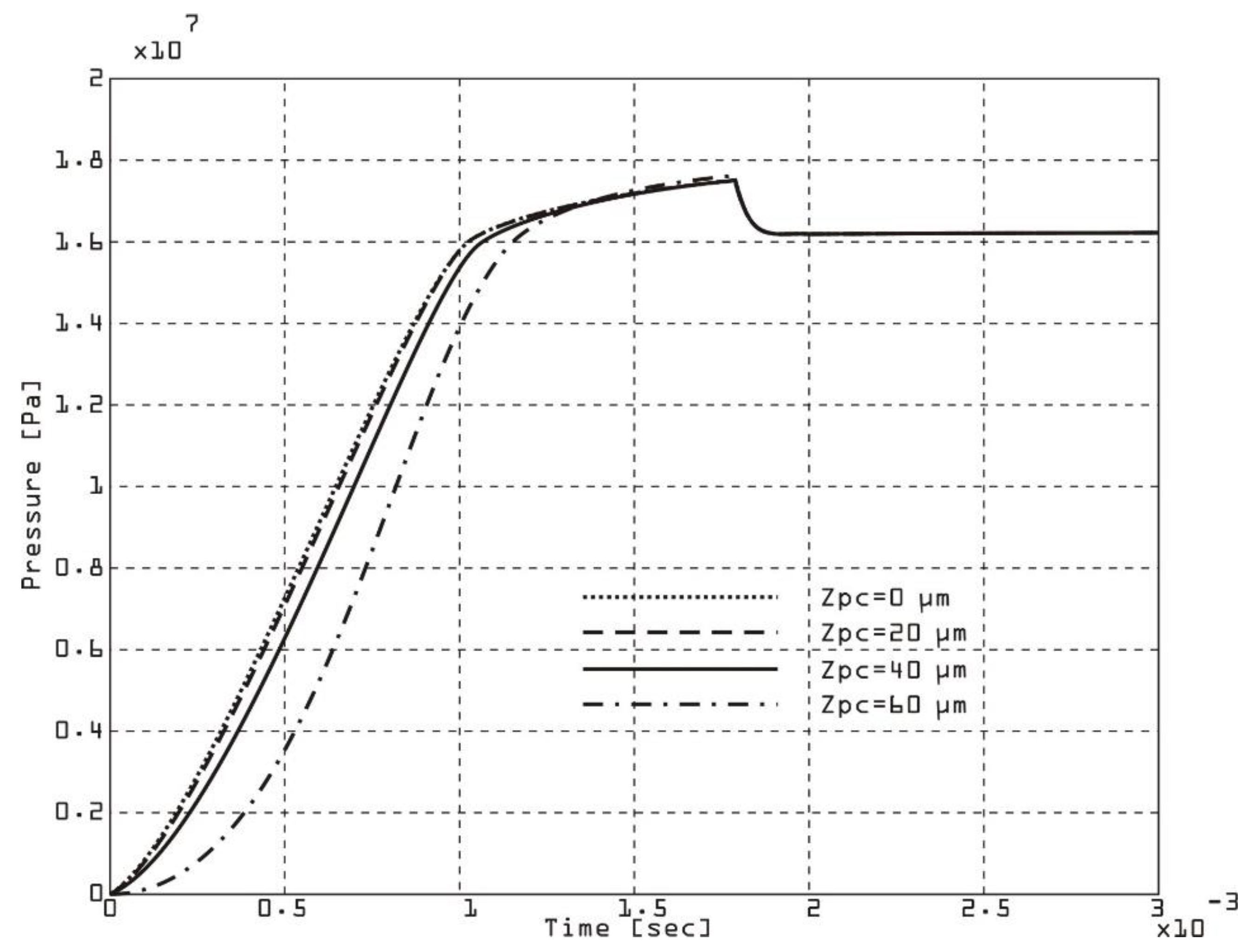
The rate of change of pressure in the chamber for different clearances in the rotor groove
Figure 14 of a double-acting vane pump is significantly affected by the movement and sealing of the vane within the groove. The clearance of the rotor groove affects the dynamics of the vanes, fluid leakage, and pressure build-up in the chamber.
The effect of the clearance between the vane and the rotor groove affects the stability of the vanes because a tighter fit reduces flapping of the vane and improves the sealing of the chamber. Excess clearance allows fluid to leak past the vane, reducing the effective pressure in the chamber. Smaller clearances increase friction, which leads to faster wear of the vane and groove. The ability of the vane to maintain a tight seal in the groove directly affects the rate of pressure rise or fall in the corresponding chamber. A small rotor groove gap improves the seal between the vane and the rotor groove, reduces leakage and results in a higher rate of pressure change and can increase friction, causing more wear on the vane and groove. A large gap increases leakage past the vane. It slows down the rate of pressure change due to loss of sealing efficiency. It leads to lower volumetric and overall efficiency. A smaller groove gap results in a steeper pressure rise and fall curve and increases volumetric efficiency and minimizes leakage. A larger groove gap causes a slower pressure rise due to increased leakage and reduces overall pump efficiency and can lead to inconsistent pressure dynamics. The optimal gap strikes a balance between minimizing leakage and avoiding excessive friction or wear. Over time, the groove clearance can increase due to wear, requiring periodic maintenance or component replacement. For precision applications (e.g., hydraulic systems with high pressure requirements), smaller clearances are critical.
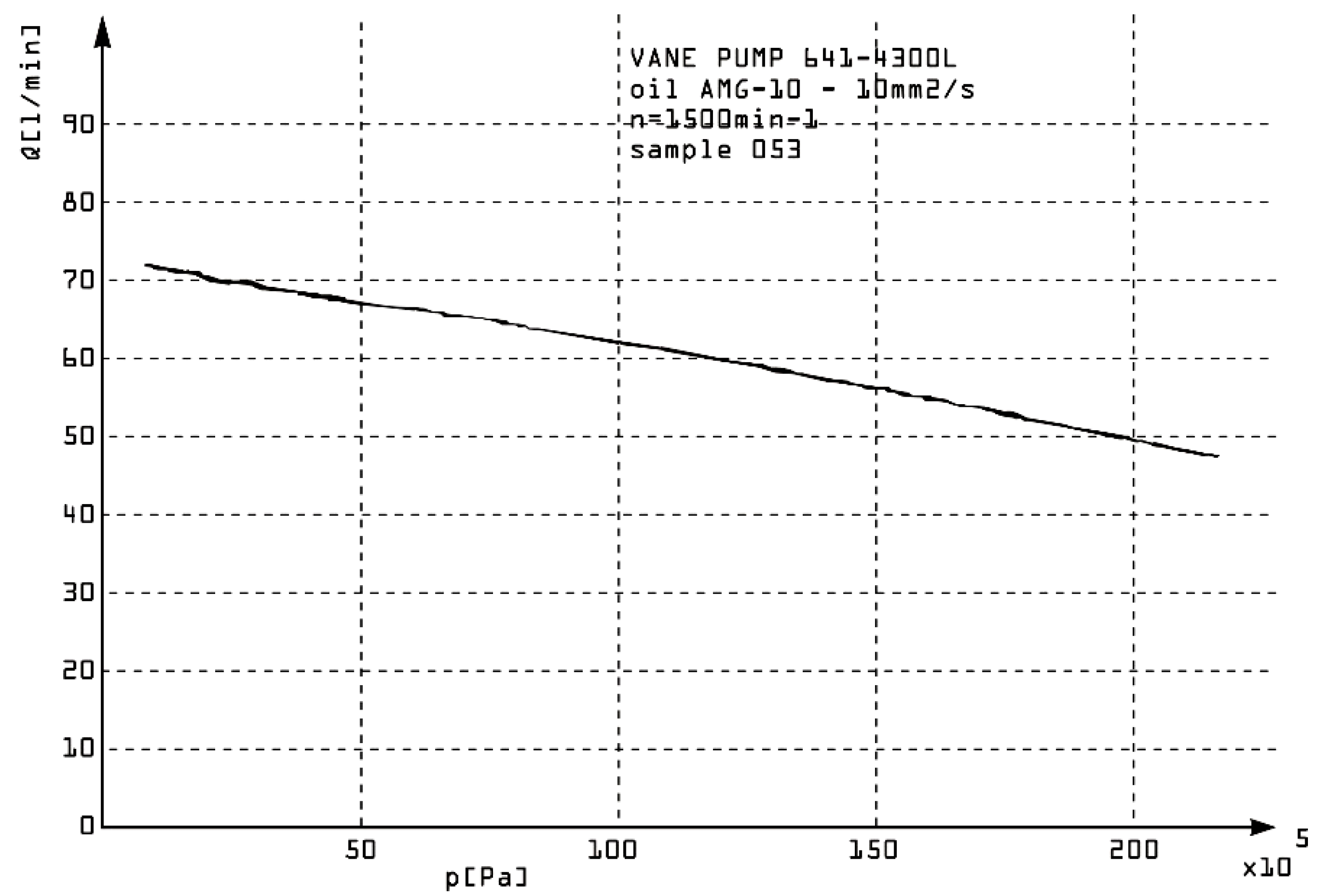
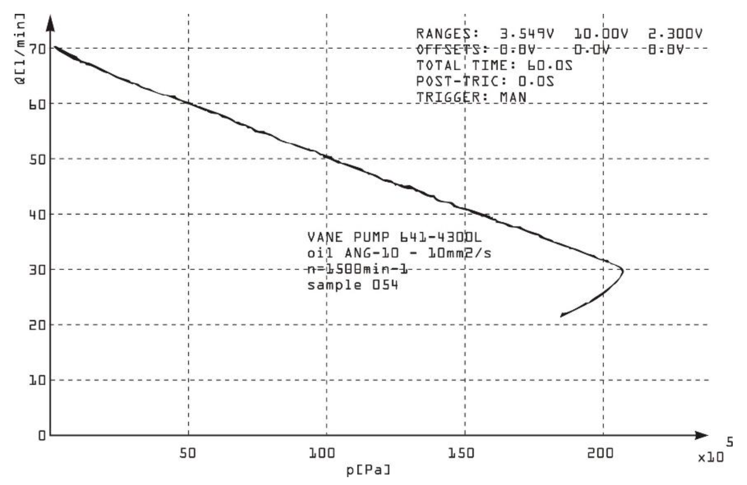
The relationship between outlet pressure and flow in a double-acting vane pump is primarily influenced by the pump design, operating parameters, and system resistance. This relationship can usually be characterized by a pump performance curve, which shows how the flow rate varies with outlet pressure under given conditions. The geometric displacement of the pump determines the maximum theoretical flow rate. Internal leakage increases with outlet pressure, reducing the effective flow rate. Higher velocity increases flow rate, but also increases friction and heat generation. Viscosity and bulk modulus affect leakage and compressibility. Outlet pressure is determined by the load or restriction in the downstream system. As resistance increases, outlet pressure increases, and flow rate may decrease due to leakage and loss of efficiency. This indicates a linear decrease in flow rate as outlet pressure increases, assuming constant velocity and viscosity. The performance curve of a double-acting vane pump shows that at low outlet pressures, the flow rate is close to the theoretical flow rate. As the outlet pressure increases, the flow rate decreases due to leakage and loss of efficiency. At very high outlet pressures, the pump may reach a stall condition, where the flow rate drops significantly. Three double-acting vane pumps (no.051, no.054 no.054) connected to a hydraulic circuit with an adjustable resistance for changing the outlet pressure were experimentally tested. The instrumentation included flow meters to measure the outlet flow and pressure sensors to monitor the outlet pressure. A procedure of gradually increasing the system resistance was applied to increase the outlet pressure and the flow rate and pressure were recorded at each step. The plot of flow rate versus outlet pressure is given in
Figure 15,
Figure 16 and
Figure 17.
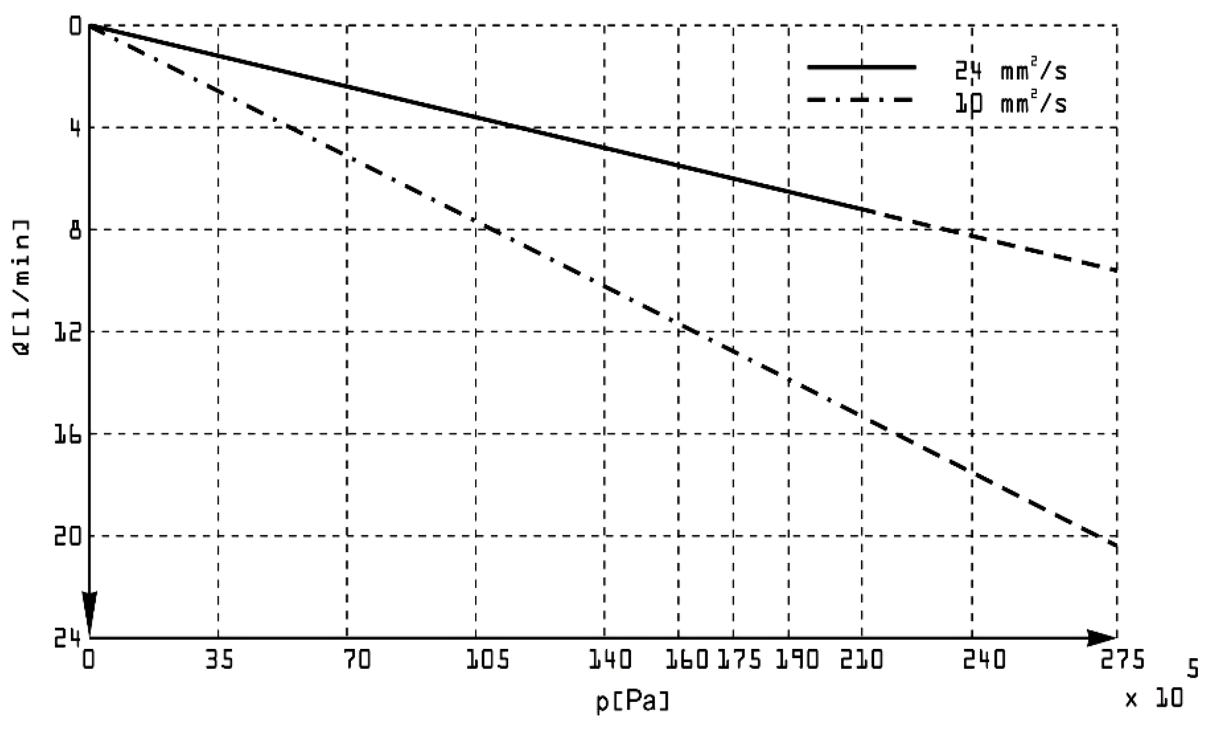
The relationship between outlet pressure and flow in a double-acting vane pump (
Figure 18) varies significantly with the use of oils of different kinematic viscosities. Viscosity affects internal leakage, friction, and overall pump efficiency, thus changing the relationship between outlet pressure and flow rate. Higher viscosity oils have advantages such as reduced internal leakage due to better sealing between components (e.g. vanes, rotor grooves, and chamber walls) and higher volumetric efficiency at higher pressures. Disadvantages include increased fluid friction, resulting in greater energy loss and heat generation. It can also lead to reduced flow at higher pressures due to increased viscous drag. Lower viscosity oils have advantages such as lower friction losses, allowing higher flow rates at low to moderate pressures. They are suitable for high-speed operation. Disadvantages are manifested by increased leakage, especially at higher pressures, reducing volumetric efficiency. They are more prone to cavitation under high pressure conditions.
5. Conclusions
The developed mathematical model accurately predicts the behavior of a double-acting vane pump, including flow rates, pressure variations, and efficiency. The model includes key parameters such as vane dynamics, clearances, and fluid properties, demonstrating its ability to effectively simulate real-world pump operation.
The study highlights the critical influence of geometric and operational parameters, such as rotor groove clearances, vane clearances, and fluid viscosity, on pump performance. These parameters significantly affect internal leakage, flow pulsations, and the rate of pressure change in the chambers.
Experimental testing confirms the significant influence of oil viscosity on pump performance. Higher viscosity oils reduce leakage and improve volumetric efficiency at higher pressures, while lower viscosity oils result in higher flow at lower pressures but suffer from efficiency loss at higher pressures.
The leakage flow through the blade gaps and rotor grooves increases with outlet pressure, leading to a decrease in effective flow rate and efficiency. The results highlight the need for clearance optimization to balance leakage reduction and friction losses.
Experimental testing validated the mathematical model, showing strong agreement between simulated and measured data for various operating conditions. This confirms the reliability of the model as a predictive tool for analyzing and optimizing vane pump performance.
The research provides valuable insight into the design and operation of double-acting vane pumps, offering guidance for improving efficiency, durability, and performance. It is particularly useful for applications where precise flow and pressure control is critical, such as hydraulic systems and power steering mechanisms.
The study suggests further research into advanced materials, surface treatments, and real-time monitoring to improve vane pump efficiency and reduce wear. Extending the model to include thermal effects and cavitation phenomena could further improve its applicability.
Author Contributions
Conceptualization, M.A., B.Ž., R.P., S.R.M., N.G.Đ., J.L.; methodology, M.A., B.Ž., R.P., S.R.M., N.G.Đ., J.L.; software, M.A., B.Ž., R.P., S.R.M., N.G.Đ., J.L.; validation, M.A., B.Ž., R.P., S.R.M., N.G.Đ., J.L.; formal analysis, M.A., B.Ž., R.P., S.R.M., N.G.Đ., J.L.; investigation, M.A., B.Ž., R.P., S.R.M., N.G.Đ., J.L.; resources, M.A., B.Ž., R.P., S.R.M., N.G.Đ., J.L.; data curation, M.A., B.Ž., R.P., S.R.M., N.G.Đ., J.L.; writing—original draft preparation, M.A., B.Ž., R.P., S.R.M., N.G.Đ., J.L.; writing—review and editing, M.A., B.Ž., R.P., S.R.M., N.G.Đ., J.L.; visualization, M.A., B.Ž., R.P., S.R.M., N.G.Đ., J.L.; supervision, M.A., B.Ž., R.P., S.R.M., N.G.Đ., J.L.; project administration, M.A., B.Ž., R.P., S.R.M., N.G.Đ., J.L.; funding acquisition, R.P. All authors have read and agreed to the published version of the manuscript.
Funding
This paper is funded by the University “Union-NikolaTesla”, Faculty of Information Technology and Engineering.
Institutional Review Board Statement
Not applicable.
Informed Consent Statement
Not applicable.
Data Availability Statement
Data are contained within the article.
Acknowledgments
The authors would like to thank Editor-in-Chief, Editor, and anonymous reviewers for their valuable reviews.
Conflicts of Interest
The authors declare no conflict of interest.
References
- Shorbagy, A.; Ivantysyn, R.; Berthold, F.; Weber, J. Holistic analysis of the tribological interfaces of an axial piston pump - Focusing on pump’s efficiency. IFK 2022, Aachen, 2022. [Google Scholar]
- Ivantysyn, R.; Shorbagy, A.; Weber, J. An approach to visualize lifetime limiting factors in the cylinder block/valve plate gap in axial piston pumps. ASME/BATH 2017 Symposium on Fluid Power and Motion Control, FPMC 2017, 2017. [CrossRef]
- Ivantysyn, R.; Shorbagy, A.; Weber, J. Investigation of the Wear Behavior of the Slipper in an Axial Piston Pump by Means of Simulation and Measurement. 12. IFK 2020, 2020. [Google Scholar]
- Ivantysyn und, J. Weber, „“Transparent Pump” – An approach to visualize lifetime limiting factors in axial piston pumps“, in ASME 2016 9th FPNI Ph.D Symposium on Fluid Power, Florianapolis, Brazil, 2016.
- Schenk, A. Predicting Lubrication Performance Between the Slipper and Swashplate in Axial Piston Hydraulic Machines. Purdue University, 2014.
- Schlösser, W. M. J.; Witt, K. Thermodynamisches Messen in der Ölhydraulik. VDMA, 1976.
- Matthies, H. J. ; Renius,K.T. Einführung in die Ölhydraulik. 2014. [CrossRef]
- Wegner, D. S. ; Löschner,F. Validation of the physical effect implementation in a simulation model for the cylinder block / valve plate contact supported by experimental investigations. IFK2016, 2016.
- Kim, J.; Jae-Youn, J. Measurement of Fluid Film Thickness on the Valve Plate in Oil Hydraulic Axial Piston Pumps (Part I). KSME International Journal http://www.dbpia.co.kr/Journal/ArticleDetail/3227503. 2003, 17, 246–253. [Google Scholar] [CrossRef]
- Bergada, J. M.; Watton, J.; Kumar, S. Pressure, Flow, Force, and Torque Between the Barrel and Port Plate in an Axial Piston Pump. Journal Dyn Syst Meas Control 2008, 130, 011011. [Google Scholar] [CrossRef]
- Manring, N. D.; Wray, C. L.; Dong, Z. Experimental studies on the performance of slipper bearings within axial-piston pumps. Journal Tribology 2004, 126, 511–518. [Google Scholar] [CrossRef]
- Kazama, T.; Tsuruno, T.; Sasaki, H. Temperature Measurement of Tribological Parts in Swash-Plate Type Axial Piston Pumps. Proceedings of the JFPS International Symposium on Fluid Power 2008, 7–2, 341–346. [Google Scholar] [CrossRef]
- Ying, J. Li. ; Xu,Y. Experimental study on churning losses reduction for axial piston pumps. IFK 2018, 2018. [Google Scholar]
- Zhou, J. , Zhou, J. & Jing, C. Experimental Research on the Dynamic Lubricating Performance of Slipper/Swash Plate Interface in Axial Piston Pumps. Chin. J. Mech. Eng. 2020, 33, 25. [Google Scholar] [CrossRef]
- G. Rizzo, G.P. Massarotti, A. Bonanno, R. Paoluzzi, M. Raimondo, M. Blosi, F. Veronesi, A. Caldarelli& G. Guarini () Axial piston pumps slippers with nanocoated surfaces to reduce friction. International Journal of Fluid Power 2015, 16, 1–10. [CrossRef]
- Paszota, Z. Theoretical and mathematical models of the torque of mechanical losses in the pump used in a hydrostatic driv. Polish Maritime Research 2012, 18, 28–35. [Google Scholar] [CrossRef]
- Casoli, P.; Pompini, N.; Riccò, L. Simulation of an Excavator Hydraulic System Using Nonlinear Mathematical Models. Strojniškivestnik - Journal of Mechanical Engineering 2018, 61, 583–593. [Google Scholar] [CrossRef]
- Zhou, J.; Zhou, J.; Jing, C. Experimental Research on the Dynamic Lubricating Performance of Slipper/Swash Plate Interface in Axial Piston Pumps. Chin. J. Mech. Eng. 2020, 33, 25. [Google Scholar] [CrossRef]
- Özmen, Ö.; Sinanoğlu, C.; Caliskan, A. Prediction of Leakage from an Axial Piston Pump Slipper with Circular Dimples Using Deep Neural Networks. Chin. J. Mech. Eng. 2020, 33, 28. [Google Scholar] [CrossRef]
- Yin, F.; Nie, S.; Xiao, S.; Hou, W. Numerical and experimental study of cavitation performance in sea water hydraulic axial piston pump. Proceedings of the Institution of Mechanical Engineers, Part I: Journal of Systems and Control Engineering 2016, 230, 716–735. [Google Scholar] [CrossRef]
Figure 2.
Main components of a vane pump.
Figure 2.
Main components of a vane pump.
Figure 3.
Schematic diagram of vane pump.
Figure 3.
Schematic diagram of vane pump.
Figure 4.
Area of silencing grooves
Figure 4.
Area of silencing grooves
Figure 5.
Schematic diagram of silencing grooves
Figure 5.
Schematic diagram of silencing grooves
Figure 6.
Idealized flow of pump.
Figure 6.
Idealized flow of pump.
Figure 7.
Negative flow that occurs due to the pre-loading process.
Figure 7.
Negative flow that occurs due to the pre-loading process.
Figure 8.
Pressure gradient varying with the type of silencing grooves.
Figure 8.
Pressure gradient varying with the type of silencing grooves.
Figure 9.
Universal test standAMS ZI 108-94262 ТYPE BAH 1622/B38-5 (3x380V, 50Hz, 100 KW).
Figure 9.
Universal test standAMS ZI 108-94262 ТYPE BAH 1622/B38-5 (3x380V, 50Hz, 100 KW).
Figure 10.
Speed of pressure change in the chamber for various values of axial clearance at the first vane.
Figure 10.
Speed of pressure change in the chamber for various values of axial clearance at the first vane.
Figure 11.
Speed of pressure change in the chamber for various values of axial clearance at the second vane.
Figure 11.
Speed of pressure change in the chamber for various values of axial clearance at the second vane.
Figure 12.
Speed of pressure change in the chamber for various values of radial clearance at the first vane.
Figure 12.
Speed of pressure change in the chamber for various values of radial clearance at the first vane.
Figure 13.
Speed of pressure change in the chamber for various values of radial clearance at the second vane.
Figure 13.
Speed of pressure change in the chamber for various values of radial clearance at the second vane.
Figure 14.
Speed of pressure change in the chamber for various values of the gap in rotor groove.
Figure 14.
Speed of pressure change in the chamber for various values of the gap in rotor groove.
Figure 15.
Dependance between the outlet pressure and the flow of the pump (sample no.053).
Figure 15.
Dependance between the outlet pressure and the flow of the pump (sample no.053).
Figure 16.
Dependance between the outlet pressure and the flow of the pump (sample no.054).
Figure 16.
Dependance between the outlet pressure and the flow of the pump (sample no.054).
Figure 17.
Dependance between the outlet pressure and the flow of the pump with oil different kinematic viscosity.
Figure 17.
Dependance between the outlet pressure and the flow of the pump with oil different kinematic viscosity.
Figure 18.
The overall structure of experiment.
Figure 18.
The overall structure of experiment.
Table 1.
The Descriptions of Parameter symbols.
Table 1.
The Descriptions of Parameter symbols.
| Symbol |
Description |
|
Variable radius of the stator |
|
Smaller radius of the stator |
|
Values of axial clearance |
|
Vane thickness |
|
Dynamic viscosity of working fluid |
|
Suction pressure |
|
Pressure in the chamber |
|
Operating pressure |
|
Values of radial clearances |
|
Angular speed of rotor |
|
Angle of rotor rotation |
|
Bigger radius of stator |
|
Outflow coefficient |
|
Cross-sectional area |
|
Density of working fluid |
|
Clearance in the gap |
|
Length of the front vane when rotor is in transmission area |
|
Pressure increment |
|
Change of volume |
|
Fluid volume at the pressure |
|
Pressure increment in the chamber between the vanes |
|
Thrust pressure of working fluid |
|
Volume of the chamber (when the chamber is in the zone of pressure change constrained by angle and bigger stator radius Rb) |
|
Angle between two adjacent vanes |
|
Vane width |
|
Disclaimer/Publisher’s Note: The statements, opinions and data contained in all publications are solely those of the individual author(s) and contributor(s) and not of MDPI and/or the editor(s). MDPI and/or the editor(s) disclaim responsibility for any injury to people or property resulting from any ideas, methods, instructions or products referred to in the content. |
© 2025 by the authors. Licensee MDPI, Basel, Switzerland. This article is an open access article distributed under the terms and conditions of the Creative Commons Attribution (CC BY) license (http://creativecommons.org/licenses/by/4.0/).