
Submitted:
17 December 2025
Posted:
18 December 2025
You are already at the latest version
Abstract
This study introduces an all-fiber optic sensing network based on fiber Bragg grating (FBG) technology for structural health monitoring (SHM) of launch vehicle payload fairings un-der extreme thermo-mechanical conditions. A wavelength–space dual-multiplexing ar-chitecture enables full-field strain and temperature monitoring with minimal sensor de-ployment. Structural deformations are reconstructed from local measurements using the inverse finite element method (iFEM), achieving sub-millimeter accuracy. High-temperature experiments verified that FBG sensors maintain a strain accuracy of 0.8 με at 500 °C, significantly outperforming conventional sensors. Under 15 MPa mechanical loading and 420 °C thermal shock, the fairing structure exhibited no damage propagation. The sensing system captured real-time strain distributions and deformation profiles, con-firming its suitability for aerospace SHM. The combined use of iFEM and FBG enables high-fidelity, large-scale deformation reconstruction, offering a reliable solution for reusa-ble aerospace structures operating in harsh environments.
Keywords:
fiber Bragg grating
; extreme thermo-mechanical coupling environment
; inverse finite element method
; payload fairing
; structural health monitoring
1. Introduction
A payload fairing (PF) is a protective structure on a rocket that shields the spacecraft from aerodynamic heating and dynamic pressure during launch. It separates immediately after the rocket reaches outer space [1]. Fairing failure can lead to mission failure and significant financial loss. Notable incidents include the Taurus XL [2], PSLV-C39 (2017), and Astra Rocket 3.3 (2022) launches, all of which failed owing to PF separation anomalies. These cases highlight the need for effective structural health monitoring (SHM) systems to ensure payload protection and fairing reliability.
SHM enables real-time detection of cracks, deformations, and separation anomalies, playing a key role in both single-use and reusable PF systems. As reusable launch components gain prominence, SHM also aids in post-recovery evaluation, reducing operational cost and enhancing safety.
Fiber Bragg grating (FBG) sensors are crucial for SHM of PFs owing to their light weight, high sensitivity, and resistance to harsh environments [3]. They enable real-time monitoring of strain, temperature, and vibration [4], thereby enhancing mission reliability and supporting PF reusability. The use of SHM technology in PFs has garnered significant attention both domestically and internationally, as evidenced by its integration in prominent launch vehicles, such as the Chinese Long March series [5] and NASA’s space launch system PF test. The next section delineates the primary content and current research status of FBGs in PF monitoring. In aerospace engineering, composite construction techniques for PFs have been investigated extensively. Building on this, Lin et al. [6] comprehensively examined the dynamics of FBG monitoring applications in spacecraft structures, including PFs. Their study emphasized sensor design and reliability validation in high-temperature, vibration, and shock environments. Wang et al. [7] proposed a multichannel FBG array network to capture vibration spectral characteristics during the launch phase and experimentally verified its performance over various vibration spectral characteristics. They later proposed a multichannel FBG array network to capture the vibration spectral characteristics of the PF during launch, experimentally verifying its accuracy in wideband vibration (0–500 Hz). Shafighfard and Mieloszyk [8] investigated FBG sensors for carbon-fiber composite PFs under complicated conditions. Li et al. [9] compared FBG with conventional piezoelectric sensors for PF vibration monitoring, demonstrating the advantages of FBG in anti-electromagnetic interference and long-term stability. Zhang et al. [10] developed a high-resolution FBG demodulation system for spacecraft PF monitoring, achieving an impressive accuracy of 500 Hz, and facilitated the concurrent acquisition of data from multiple sensors, enabling real-time data processing. Shi et al. [11] investigated the thermal–structural coupling effect of a composite PF in high-temperature environments. They embedded FBG sensors to monitor real-time temperature and strain distributions and analyzed the dynamic strain response of the FBG when the PF separated. Furthermore, they verified sensor data reliability through finite-element simulations. Mei et al. [12] tested the FBG stability at extreme temperatures above 300 ℃ and proposed a temperature compensation algorithm applicable to rocket PF thermal protection system monitoring. Similarly, Ranasinghe et al. [13] reviewed fiber-optic sensing applications in aerospace thermal and structural monitoring, specifically focusing on FBGs in PFs, wing leading edges, and other aircraft components. In collaborative research on FBGs and fairings, the China Aerospace Science and Technology Group and other academic institutions have integrated FBGs into carbon fiber reinforced polymer PF specimens. They have also developed an FBG-based SHM system that facilitates real-time strain and temperature monitoring [14]. Although numerous studies have focused on fundamental applications such as damage detection and separation monitoring, the domains of data processing algorithms and sensor integration processes can be improved considerably. Organizations such as NASA, the European Space Agency, and SpaceX have attained high proficiency in integrating FBGs with PFs [15,16,17,18]. Although numerous issues in practical engineering applications have been addressed successfully, others remain unresolved. The results obtained from this study should prove beneficial in this regard.
This study dynamically monitors PFs using FBG sensors. We deploy these sensors near the separation point of the PF to observe stress and dynamic responses during separation. Additionally, we analyze the thermal coupling effect by utilizing wavelength shift characteristics. The results of this analysis are combined with the strain data to examine the effect of thermal loads on the composite structure. This ensures the temperature safety of the internal payloads. The thermal protection design of the PF is also optimized. Finally, we ensure that the PF can separate smoothly after entering outer space, thereby preventing separation failure and subsequent mission failure. This study explores fiber-optic sensor applications, providing an in-depth understanding of large structure SHM. It also proposes a feasible method for testing PFs under thermally coupled loads by generating meaningful data. Given the expanding demand for space missions, further research in this field is expected to catalyze advances in PF design and monitoring technology.
The remainder of this paper is organized as follows: Section 2 introduces the background, followed by a detailed examination of the FBG sensing principle and strain sensitivity calibration experiment. Section 3 provides a detailed description of the PF of the launch vehicle as the test subject, along with an examination of the loading conditions and FBG sensor application. Section 4 analyzes the results, including temperature and strain sensing. Section 5 employs the inverse finite element method (iFEM) to reconstruct the structural deformation displacement field, and Section 6 concludes the paper.
2. Monitoring and Reconstruction Methods
2.1. Basic Theory of FBG Sensors and Testing
FBG is a fiber-optic sensing component that periodically modulates the refractive index of the fiber core. This creates a narrow-band filter within the core. When broad-spectrum light passes through the FBG, the grating reflects narrow-band light with a central wavelength while transmitting other wavelengths. Changes in temperature and strain induce changes in the period and refractive index of FBG, thereby altering its reflection and transmission spectra.
The fiber is subjected to axial stresses, resulting in axial strain ε. The strains in the two directions perpendicular to the axis are -με (where μ denotes the Poisson’s ratio), and the shear stress is zero. Assuming the three directions align with the axial direction of the fiber, and directions 1 and 2 correspond to the cross-sectional directions of the fiber, the strain tensor S applied to the fiber can be expressed as follows:
The grating period change designated as is influenced by strain denoted as ε, according to the following equation:
where denotes the femtosecond FBG (FsFBG) period.
The change in effective refractive index is given by:
where and denote the optical elasticity coefficients of the fiber that define the effective optical elasticity coefficient as follows:
and
Consequently, the Bragg wavelength drift at ambient temperature is directly proportional to the strain. For an ordinary quartz fiber, the effective elasticity coefficient is approximately 0.22. Assuming a wavelength of 1550 nm, the drift is approximately 1.21 pm for every 1 mm change in strain ε. However, in an actual high-temperature monitoring environment where an FBG is mounted on a component using ceramic adhesive, the temperature characteristics of the adhesive and its connection with both the component and optical fiber affect the strain transfer. Therefore, the FBG strain response requires further refinement.
2.2. Nonlinear Characterization Study of FsFBG
FsFBG was fabricated by directly inscribing a femtosecond laser point-by-point onto the fiber core. This sensor remained stable during extended operation at temperatures up to 850 ℃ and even survived brief exposure to 1000 ℃. Consequently, it is particularly well-suited for strain measurements in high-temperature environments. The manufacturing process is shown in Figure 1 [19].
The peak reflection wavelength () of the FBG can be expressed as follows:
Thus,
Accordingly, the Bragg wavelength of the FBG is subject to variation in accordance with refractive index and grating period . When the temperature changes, denoted by , the alteration in the grating period, indicated by , is attributable to the thermal expansion effect:
where denotes the thermal expansion coefficient of the fiber. The change in effective refractive index, designated as , caused by the thermo-optic effect, is expressed as follows:
where denotes the thermo-optic coefficient of the fiber, representing the rate of change of refractive index with temperature. Substituting Equations (7) and (8) into Equation (6) yields:
where KT denotes the temperature coefficient of the Bragg grating. When temperature fluctuations remain within small ranges, the thermal expansion coefficient and the thermo-optic coefficient of the fiber can be regarded as constant. Consequently, Bragg wavelength drift can be modeled as a linear function of temperature, with a correlation coefficient R² > 0.99 for temperature variations below 150 °C. However, PF temperatures frequently exceed this range during actual operation. Consequently, the response of FsFBG to temperature becomes nonlinear, necessitating precise calibration. Given the thermal optical and thermal expansion coefficients of the fiber, the change in the FsFBG center wavelength versus temperature is expressed as follows:
where denotes the temperature-induced wavelength drift, T denotes the temperature, and to are the center wavelength versus temperature coefficients.
Therefore, an acrylic structural adhesive (Ergo 1690) was used to attach the FsFBG sensors to the test piece. Figure 2 depicts the sensor arrangement at 20 ℃. The FsFBG was attached to the front of the standard tensile member, with strain gauges attached to the back. Strain was generated using a high-temperature tensile machine, and the strain gauge data were collected in real-time using a static strain gauge (XL2118B). A fiber grating demodulation instrument (TV1600) measured the FsFBG wavelength drift in real-time. Thermocouples monitored the temperature to obtain the strain measurements from the strain gauges and the FsFBG center-wavelength drift over time.
During the temperature calibration test, changes in the thermocouple temperature and FsFBG wavelength were recorded over time. The initial FsFBG wavelength at 20 ℃ served as a reference, from which the wavelength drift was obtained. Polynomial constants were fitted by curve-fitting the collected temperature and wavelength drift values in chronological order.
2.3. Theoretical Study of Strain-Based Structural Deformation Reconstruction
This subsection addresses the challenges of space limitations and large-area occlusion in measurement environments while ensuring real-time deformation monitoring of components. Accordingly, the theory of structural deformation reconstruction relies on strain information collected by fiber grating sensors. The objective is to achieve high-precision, real-time, in-situ deformation monitoring of the workpiece positioner. The iFEM utilizes various error functions and problem-specific finite element approximations to address the inverse problem of full-field shape reconstruction. The displacement distribution of the structure was obtained using displacement calculation equations. Inverse cell selection depends on the structural characteristics under consideration [20,21].
iFEM is a numerical method for solving partial differential equations. It uses the least squares method to relate the calculated strain to the theoretical strain to obtain the least squares function:
The least squares difference of a unit can be expressed as follows:
where corresponds to the kth strain measurement, which is calculated from the strain measurements at n discrete locations:
where represents a metric coefficient that ensures unit consistency of the summation terms in the equation, and denotes a dimensionless coefficient that quantifies the correlation strength between the measured and theoretically calculated strains.
The error function, denoted by , is derived by varying the unknown vector of nodal degrees of freedom and setting it to zero. This process yields the minimum value of the error function, denoted by , and ultimately leads to the following unit matrix equation:
Matrix A depends on the position of the strain transducer, and vector b relies on the experimentally measured strain data. The unknown nodal degrees of freedom are calculated as according to Equation (15), by introducing a geometric displacement boundary condition to prevent rigid-body motion.
Given that the iFEM formulation only discretizes the strain–displacement relationship, the method does not require knowledge of the material properties, damping properties, or applied loads of the test member. Consequently, the iFEM is well-suited for both static and dynamic loading problems (Figure 3) [22,23].
3. High-Temperature Strain Tests for PF
The PF comprised the ZL205A aluminum alloy and was coated externally with a heat-insulating layer. It had a diameter of 0.4 m and was 1.4 m high. The PF was categorized into three sections: a 0.65 m high top section, middle section of 0.5 m, and bottom section of 0.25 m. An iron hoop fixture, positioned 0.4 m from the top on one side, was connected to an actuator to apply the force load. The other side was anchored to a steel cable fixed to the ground to maintain the level of the hoop and prevent tipping during loading. The PF was encircled by three quartz heating tubes to apply thermal loads, positioned at the same height as its three components. Its base was bolted to the foundation and secured with a ring of steel cables to prevent excessive bending moments from stressing the structure. The experimental design is illustrated in Figure 4(a).
During tensile loading, three sets of lampshades (upper, middle, and lower) applied heat to the test pieces. Figure 4(b) depicts the resulting force and thermal loading curves. The tension force increased linearly in the range of 0–5.2 kN over 82 s, then unloaded, reducing to 0 N at 110 s. In the initial 42 s, only tension was applied, with the force increasing linearly from 0 to approximately 2.7 kN. Heating of the upper, middle, and lower shades then began, with heat flow reaching its maximum at 82 s, achieving 305, 220, and 200 kW/m2, respectively. The cooling process ensued after a 10-s interval. After 110 s, the values decreased to 32 kW/m2, 32 W/m2, and 22 kW/m2, respectively. The heat flow rate further decreased to zero after 137 s.
The FBGs were arranged as depicted in Figure 5(a) to detect the strains during the force-thermal loading test. A total of 18 FBGs, comprising six strain rosettes, were affixed to each of the upper, middle, and lower sections of the test piece and labeled with symbols –. A temperature-compensated FBG sensor was positioned adjacent to each strain rosette and divided into four channels for connection to a fiber grating demodulator (TV125). As illustrated in Figure 5(b), this sensor rejects the effect of temperature on wavelength change. The temperature-compensated FBG sensor utilizes a metal capillary sleeve over the FBG sensor grid to isolate force, rendering it exclusively sensitive to temperature variations. This FBG arrangement monitored strain at multiple key points on the PF.
4. Temperature and Strain Sensing Data Analysis
We eliminated the temperature effect on the sensors and rectified it using the strain sensitivity coefficient. This enabled us to obtain strain versus time for different sensors (Figure 6).
As shown in Figure 6, strain analysis on the left side of the PF at locations , , and using 90°-arranged FBGs revealed peak strains of 1180 after 115 s at point , 1090 after 123 s at point , and 530 after 135 s at point , decreasing from top to bottom. At approximately 50 s, the strain changes were minimal (<100 ) owing to negligible tensile force deformation, which was significantly lower than the thermal expansion effects.
For the 45°-arranged FBGs, peak strains were 720 after 110 s at , 370 after 120 s at , and 280 after 130 s at . The strain trend mirrored that of the 90°-arranged FBGs but with consistently lower values.
For the 0°-arranged FBGs, peak strains were 750 after 120 s at , 1170 after 140 s at , and 850 after 140 s at . The strain at point (upper section) was lower owing to the iron hoop, whose thermal expansion—half that of the ZL205A aluminum alloy—restricted the horizontal deformation, leading to reduced strain.
FBGs with a 45° configuration attained the peak strain earlier than those with 90° and 0° configurations. Their strain then stabilized with a variation under 200 , similar to post-unloading behavior.
A comparative analysis of the maximum strain values at each location is shown in Figure 7. Figure 8 shows that the upper PF positions and attain their maximum value initially, with minimal time disparity among other sensor positions. Peak principal strain variations (black and red lines) at the upper and lower ends were negligible. The largest principal strains (1700 ) occurred in the middle of the left side, whereas the smallest (800 ) occurred in the middle of the right side. Figure 9(a) presents a cloud map of the principal strains in the PF, illustrating the principal strain information at each location within the monitoring range of the sensor.
Principal strain direction was also evaluated. As shown in Figure 9(b), the dominant orientation at the upper and lower right-side positions stabilized at ~43°, and ~33° in the middle. These results align with the rosette configuration and confirm the directional response under complex thermo-mechanical coupling. The spatial distribution of principal strain is presented in Figure 6f. A clear gradient was observed from top to bottom, with higher strain concentrations in the upper and middle regions. The measurements highlight the combined effect of thermal expansion and mechanical tension, validating the ability of the sensor network to capture global deformation patterns.
5. Structural Displacement Reconstruction
Based on the iFEM algorithm, the left and right sides of the PF were divided into three vertical elements. Strain data from multiple orientations in each region were used to reconstruct the displacement fields through inverse stiffness matrix calculations. Table 1 summarizes the displacements at six critical nodes on the PF structure.
The upper section exhibited the largest displacements, with the displacements of nodes b and a reaching 27.3 mm and 19.7 mm, respectively. The displacements decreased toward the base, where nodes e and f exhibited minimal movement (≤2 mm). This gradient reflects the mechanical boundary conditions and the combined effect of thermal expansion and tensile loading. Using these nodal results, the displacement field was interpolated to reconstruct the full-surface deformation across the PF. As shown in Figure 10(a), the maximum deformation occurred near the upper left region, consistent with earlier strain measurements. The deformation field demonstrates clear spatial gradients, providing insights into structural flexibility under high-temperature conditions.
The time evolution of PF morphology is shown in Figure 10(b). The displacement increased steadily during the loading and heating phases, with peak deformation occurring at ~110 s. The response exhibited both transient and sustained deformation, capturing both elastic and thermal expansion components. This indicates that the iFEM–FBG system can effectively resolve real-time shape evolution under coupled loads.
The reconstructed displacement resolution surpassed 0.1 mm/m, exceeding typical point-wise strain-based estimations. This enabled detailed identification of nonlinear stiffness changes, asymmetric separation behavior, and local accumulation of thermal strain. Such insight is critical for preventing mistimed separation and sealing mismatches in future reusable aerospace structures.
6. Conclusions
This study verified the potential reliability of FBG sensors in large-scale aerospace structures by applying them to the thermodynamically coupled SHM of launch vehicle PFs. Experimental findings demonstrated the FBG capacity of the sensor to precisely measure temperature and strain under extreme conditions, such as high temperatures and pressures. This capability overcomes the limitations of conventional sensing technologies and provides effective technical support for real-time monitoring of aerospace structures. The displacement field reconstructed using the iFEM further demonstrates the application value of FBG sensors in structural deformation analysis.
This study introduced FBG sensors to the thermal coupling test of launch vehicle PFs, overcoming technical limitations of conventional electrical sensing in environments with high temperatures, high pressures, and electromagnetic interference. The all-fiber optic sensing network enables simultaneous, high-speed acquisition and transmission of multipoint temperature and strain data, offering a high-precision solution to SHM of ultra-high-speed vehicles under complex conditions. The all-fiber multiplexing grouping of the FBG sensor network is a key innovation.
We constructed an all-fiber-optic sensing network architecture using wavelength-space dual multiplexing technology. This architecture resolved the challenge of simultaneously monitoring multiple locations and physical quantities across large aerospace structures. When combined with iFEM, our innovative inversion of strain data into a structural displacement field enabled cross-scale analysis, moving from local measurements to global deformation reconstruction. This significantly improved the intuition and accuracy of SHM and assessment.
Additionally, we established a dual verification system for structural strength and sensor performance in thermal coupling tests. A comparison of the measurement error distribution (<5%) of FBG and strain gauges was performed to systematically quantify the measurement reliability of FBG sensors in high-temperature environments above 500 °C for the first time. This validation method provided standardized data support for subsequent high-temperature tests.
Optimizing FBG sensor performance for higher temperature ranges will be a key future research direction, adapting to increasingly demanding engineering environments. Concurrently, sensor arrangement and data processing algorithms must be enhanced to improve monitoring accuracy and computational efficiency. This study provides significant experimental data and technical expertise in aerospace SHM, establishing a foundation for advancing related technologies and engineering applications.
7. Patents
This section is not mandatory but may be added if there are patents resulting from the work reported in this manuscript.
Author Contributions
Zifan He: Conceptualization; Data curation; Formal analysis; Methodology; Software; Validation; Writing—original draft. Xingguang Zhou: Resources. Jiyun Lu: Conceptualization; Formal analysis; Methodology; Project administration; Supervision; Writing—review and editing; Funding acquisition. Shengming Cui: Conceptualization; Formal analysis; Methodology; Validation; Writing—original draft. Hanqi Zhang: Methodology. Qi Wu: Conceptualization; Formal analysis; Methodology; Project administration. Hongfu Zuo: Project administration; Supervision.
Funding
This work was supported in part by the Key Program of the National Natural Science Foundation of China [Grant number: 2024YFF0508400]; Project Funded by the 173 Basic Strengthening Program [Grant number: 2020-JCJQ-ZD-125-00]; the National Natural Science Foundation of China Joint Fund Key Project under Project Name: Research on Key Technologies for Target-Oriented Intelligent Maintenance in Aviation Engine Workshops [grant number U2133202], and Special Funds of 2023 Jiangsu Provincial Science and Technology Plan (First Batch of Innovation Capacity Building Plan).
Data Availability Statement
Data will be made available upon reasonable request.
Acknowledgments
We would like to thank Editage (www.editage.cn) for English language editing.
Conflicts of Interest
The authors declare no conflicts of interest. The funders had no role in the design of the study; in the collection, analyses, or interpretation of data; in the writing of the manuscript; or in the decision to publish the results.
Abbreviations
The following abbreviations are used in this manuscript:
| FBG | Fiber Bragg grating |
| SHM | Structural health monitoring |
| iFEM | inverse finite element method |
| PF | Payload fairing |
| FsFBG | Femtosecond FBG |
References
- Liu, Y.; Wang, G.; Zhu, H.; Ye, Z. Numerical analysis of transonic buffet flow around a hammerhead Payload Fairing. Aerosp. Sci. Technol. 2019, 84, 604–619. [Google Scholar] [CrossRef]
- National Aeronautics and Space Administration. Report number NASA/TP-2011-217152; Taurus XL failure review board final report. US Government Printing Office, 2011.
- Kok, S.P.; Go, Y.I.; Wang, X.; Wong, M.L.D. Advances in Fiber Bragg Grating (FBG) Sensing: A review of conventional and new approaches and novel sensing materials in harsh and emerging industrial sensing. IEEE Sens. J. 2024, 24, 29485–29505. [Google Scholar] [CrossRef]
- Gao, Z.; Zhu, X.; Fang, Y.; Zhang, H. Active monitoring and vibration control of smart structure aircraft based on FBG sensors and PZT actuators. Aerosp. Sci. Technol. 2017, 63, 101–109. [Google Scholar] [CrossRef]
- Zhuang, L.; Yulin, Z. Deformation reconstruction and high-precision attitude control of a launch vehicle based on strain measurements. Int. J. Aerosp. Eng. 2021, 2021, 1–20. [Google Scholar] [CrossRef]
- Lin, W.; Wang, B.; Peng, G.; Shan, Y.; Hu, H.; Yang, Z. Skin-inspired piezoelectric tactile sensor array with crosstalk-free row+column electrodes for spatiotemporally distinguishing diverse stimuli. Adv. Sci. (Weinh) 2021, 8, 2002817. [Google Scholar] [CrossRef] [PubMed]
- Wang, H.; Zhao, J.; Xue, Y.; Huang, Z.; Zheng, S.; Ma, X. Application of Stewart platform in the low-frequency vibration characteristic test of space truss deployable antenna on satellite. Int. J. Aerosp. Eng. 2022, 2022, 1–8. [Google Scholar] [CrossRef]
- Shafighfard, T.; Mieloszyk, M. Model of the temperature influence on additively manufactured carbon fibre reinforced polymer samples with embedded fibre Bragg Grating sensors. Materials (Basel) 2021, 15, 222. [Google Scholar] [CrossRef] [PubMed]
- Li, D.; Wang, S.; Yuan, H.; Li, D. Software and applications of spatial data mining. Wiley Interdiscip. Rev.: Data Min. Knowl. Discov. 2016, 6, 84–114. [Google Scholar] [CrossRef]
- Zhang, J.; Zhu, T.; Zhou, H.; Li, Y.; Liu, M.; Huang, W. Modulated pulses based high spatial resolution distributed fiber system for multi-parameter sensing. arXiv 2016. [Google Scholar] [CrossRef] [PubMed]
- Shi, T.; Liu, C.; Zhao, Z.; Yu, B.; Liu, C.; Li, X. Rigid–flexible coupling dynamics of a threaded reusable low-shock spacecraft separation device. Nonlinear Dyn. 2025, 113, 4999–5021. [Google Scholar] [CrossRef]
- Mei, W.; Liu, Z.; Wang, C.; Wu, C.; Liu, Y.; Liu, P.; Xia, X.; Xue, X.; Han, X.; Sun, J.; et al. Operando monitoring of thermal runaway in commercial lithium-ion cells via advanced lab-on-fiber technologies. Nat. Commun. 2023, 14, 5251. [Google Scholar] [CrossRef] [PubMed]
- Ranasinghe, K.; Sabatini, R.; Gardi, A.; Bijjahalli, S.; Kapoor, R.; Fahey, T.; Thangavel, K. Advances in integrated system health management for mission-essential and safety-critical aerospace applications. Prog. Aerosp. Sci. 2022, 128, 100758. [Google Scholar] [CrossRef]
- Wen, X.; Sun, Q.; Li, W.; Ding, G.; Song, C.; Zhang, J. Localization of low velocity impacts on CFRP laminates based on FBG sensors and BP neural networks. Mech. Adv. Mater. Struct. 2022, 29, 5478–5487. [Google Scholar] [CrossRef]
- Colicci, T.; Noonan, A.; Anilkumar, A. Structural health monitoring for launch vehicle reusability using Fiber Bragg Grating written optical fiber. AIAA SCITECH 2025 Forum, Orlando, FL, USA, 6–10 Jan 2025; American Institute of Aeronautics and Astronautics: Virginia, 2025; 15. [Google Scholar] [CrossRef]
- Hegde, G.; Asokan, S.; Hegde, G. Fiber Bragg Grating sensors for aerospace applications: A review. ISSS J. Micro Smart Syst. 2022, 11, 257–275. [Google Scholar] [CrossRef]
- Nosseir, A.E.S.; Slejko, E.A.; Cervone, A.; Oton, C.J.; Di Pasquale, F. Composite structures with embedded fiber optic sensors: A smart propellant tank for future spacecraft applications. Acta Astronaut. 2024, 223, 144–158. [Google Scholar] [CrossRef]
- Parker, A.R.; Chan, H.M.; Lopez-Zepeda, J.; Schallhorn, P.A. Design, fabrication, testing and validation of a ruggedized Fiber Optics Sensing System (FOSS) for launch application. AIAA SCITECH 2024 Forum, Orlando, FL, USA, 8–12 Jan 2024; American Institute of Aeronautics and Astronautics: Virginia, 2024. [Google Scholar] [CrossRef]
- He, J.; Xu, B.; Xu, X.; Liao, C.; Wang, Y. Review of femtosecond-laser-inscribed fiber Bragg Gratings: Fabrication technologies and sensing applications. Photon. Sens. 2021, 11, 203–226. [Google Scholar] [CrossRef]
- Groh, R.M.J.; Tessler, A. Computationally efficient beam elements for accurate stresses in sandwich laminates and laminated composites with delaminations. Comput. Methods Appl. Mech. Eng. 2017, 320, 369–395. [Google Scholar] [CrossRef] [PubMed]
- Kefal, A.; Tessler, A.; Oterkus, E. An efficient inverse finite element method for shape and stress sensing of laminated composite and sandwich plates and shells. NTRS-NASA Technical Reports Server, 2018, Document ID: 20180004525. Available online: https://ntrs.nasa.gov/citations/20180004525.
- Savino, P.; Tondolo, F.; Gherlone, M.; Tessler, A. Application of inverse finite element method to shape sensing of curved beams. Sensors (Basel) 2020, 20, 7012. [Google Scholar] [CrossRef] [PubMed]
- Truong, V.H.; Le, Q.H.; Lee, J.; Han, J.W.; Tessler, A.; Nguyen, S.N. An efficient neural network approach for laminated composite plates using refined zigzag theory. Compos. Struct. 2024, 348, 118476. [Google Scholar] [CrossRef]
Figure 1.
Preparation technology of FsFBG.
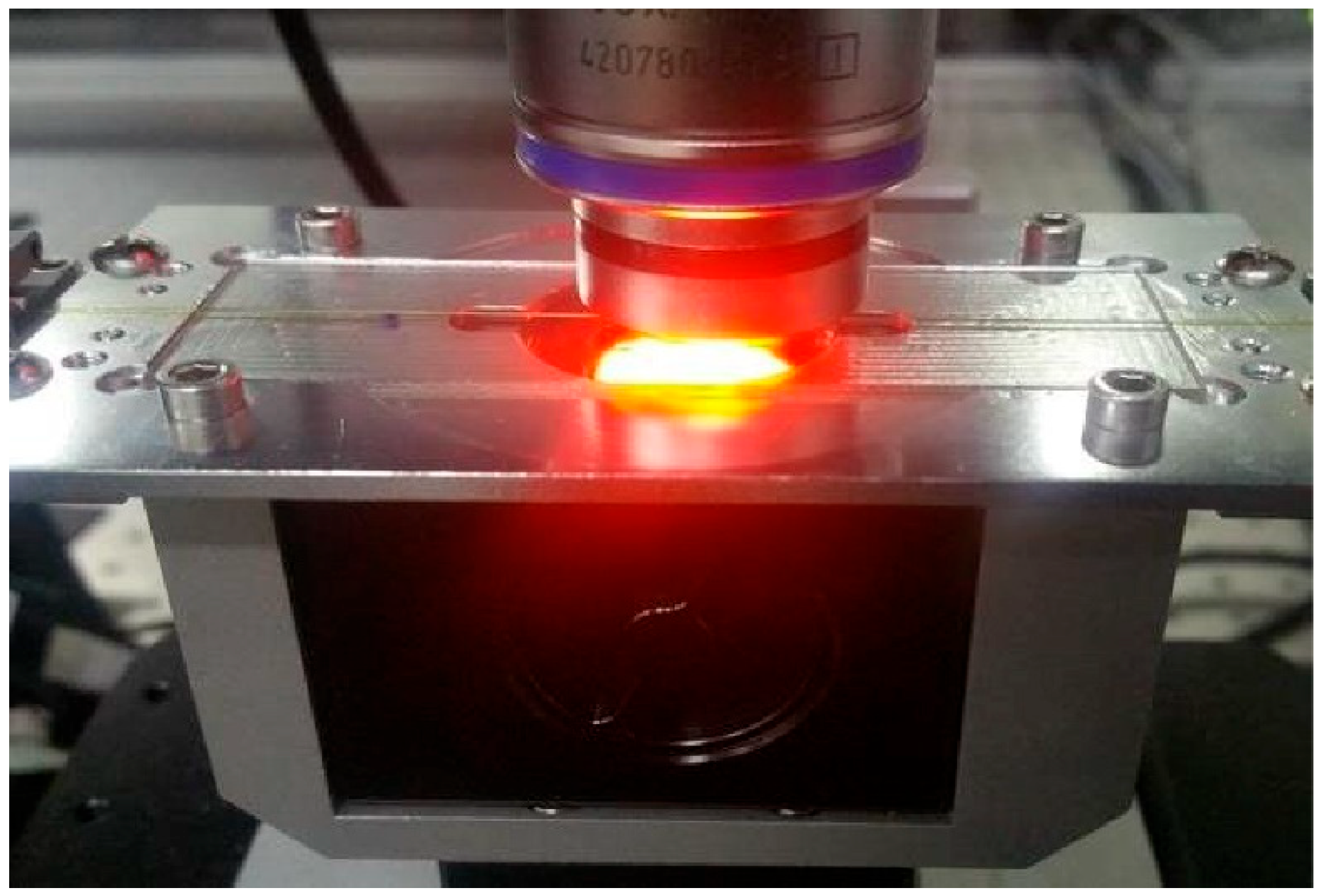
Figure 2.
Strain sensitivity calibration experiments for FsFBG.
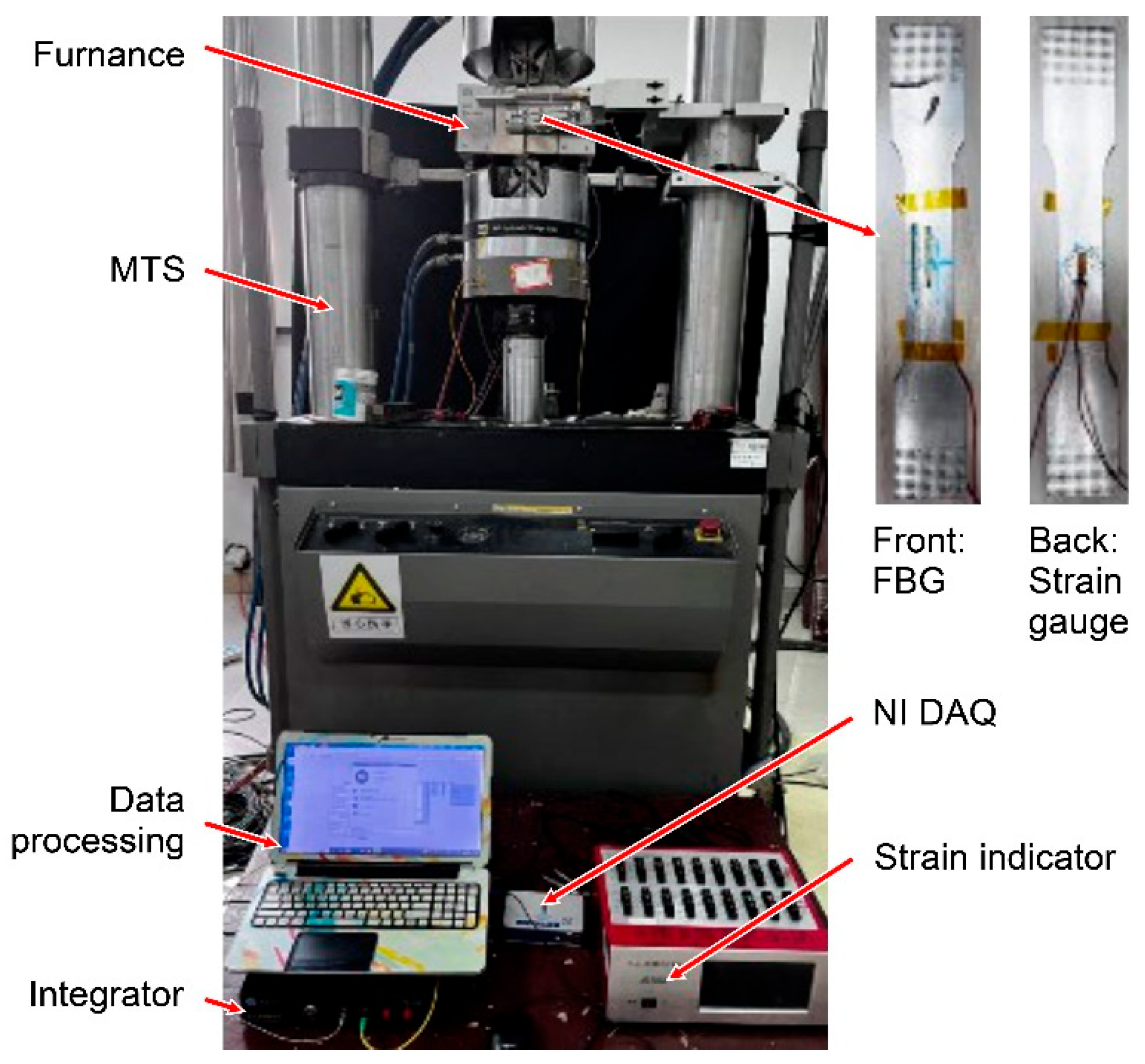
Figure 3.
iFEM solution procedure.
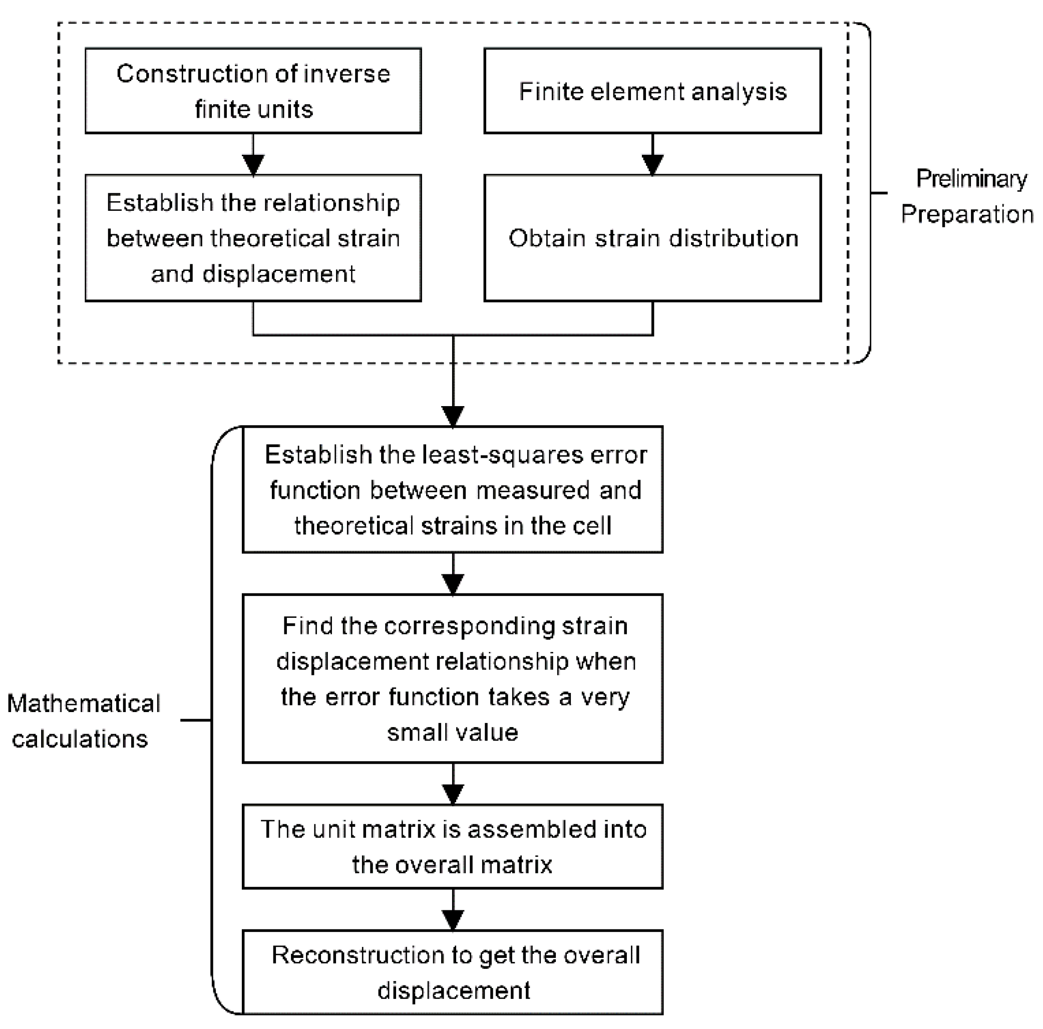
Figure 4.
Experimental setup and loading protocol.
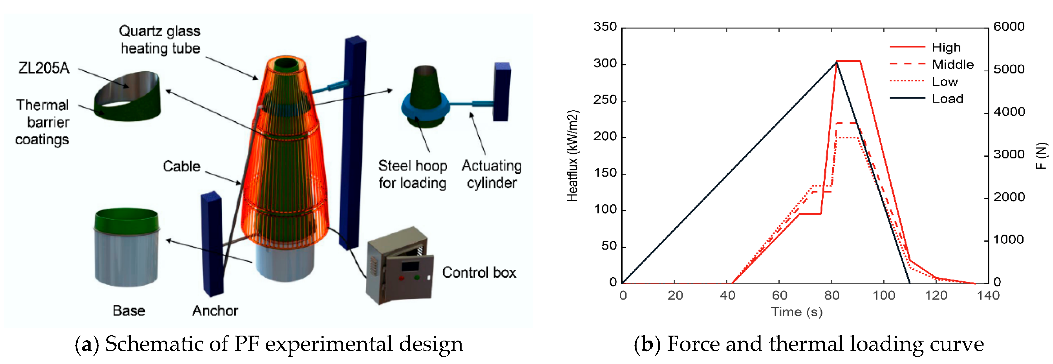
Figure 5.
Sensor layout and physical deployment.
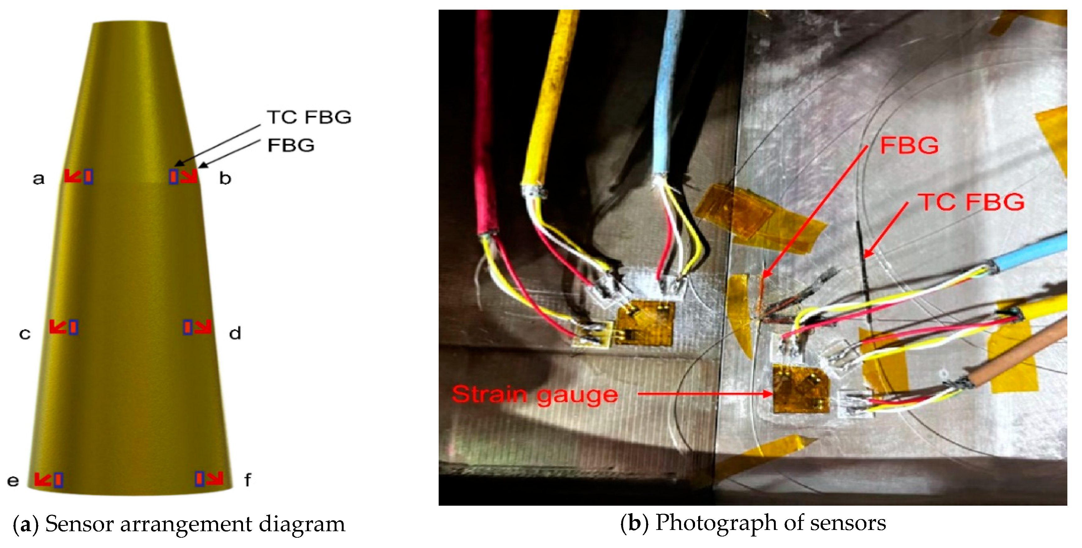
Figure 6.
Modified strain versus time curve at six locations on the PF.
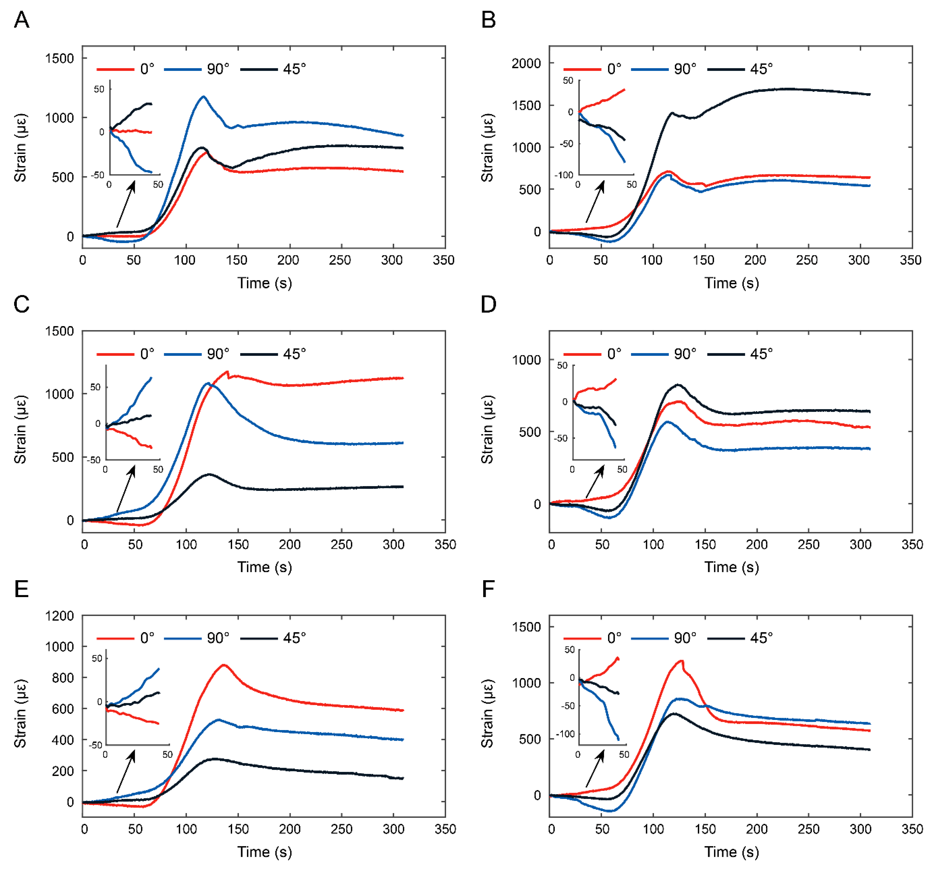
Figure 7.
Comparison of maximum strain at each position.
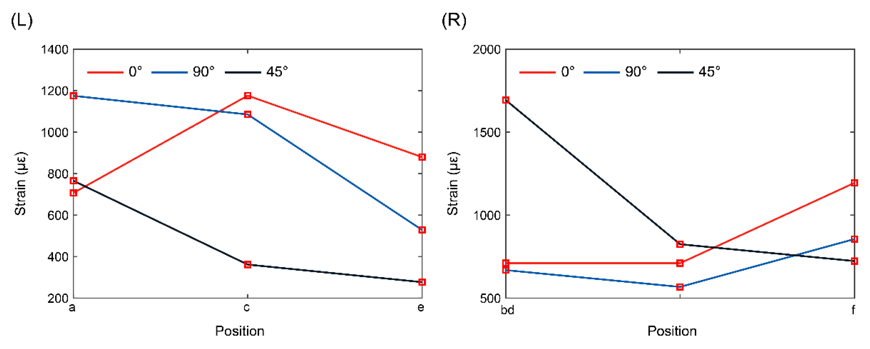
Figure 8.
Variation curves of principal strains at different positions.
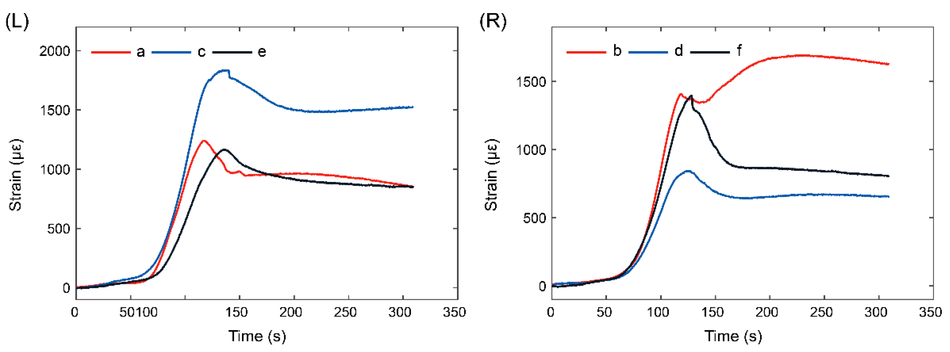
Figure 9.
Strain and deformation characteristics under thermo-mechanical loading.
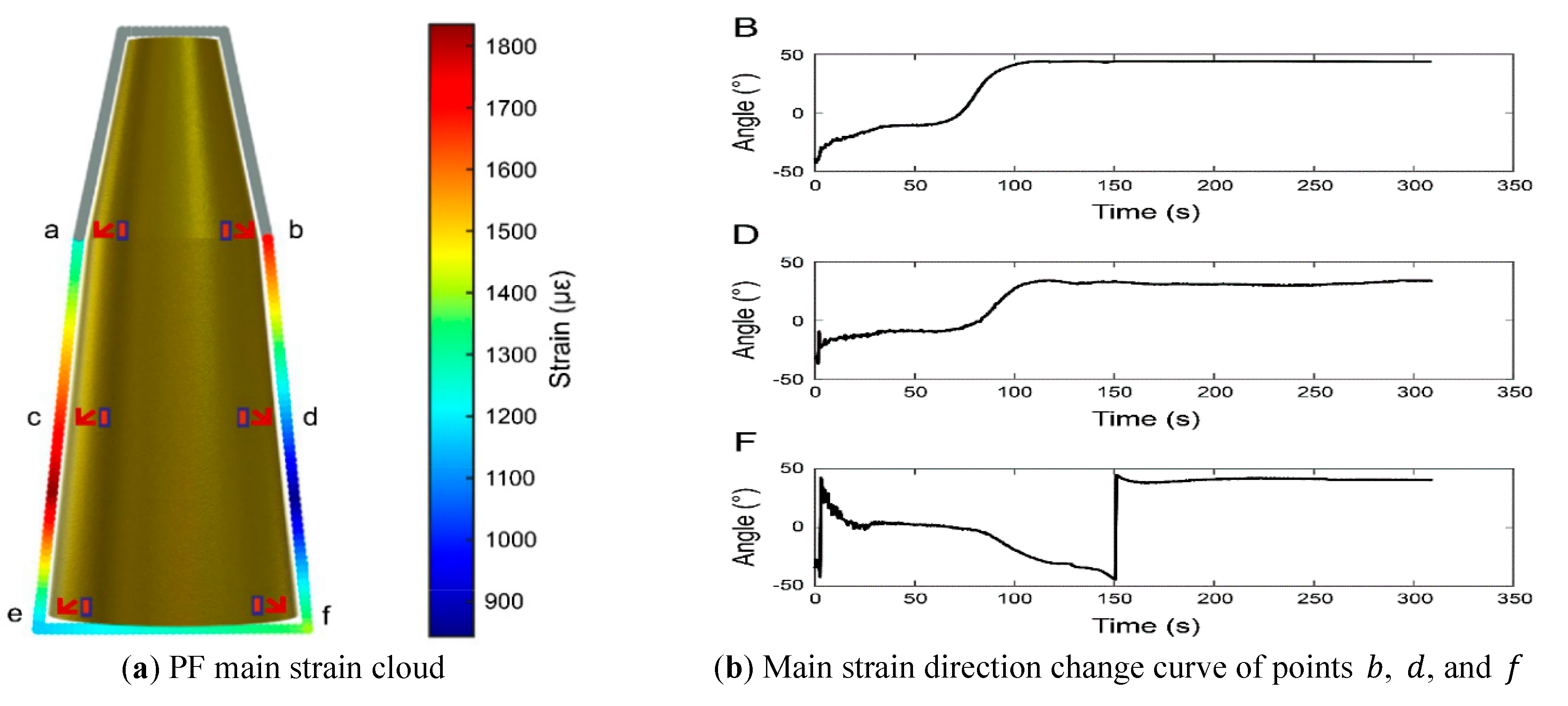
Figure 10.
Reconstructed displacement field and temporal evolution.
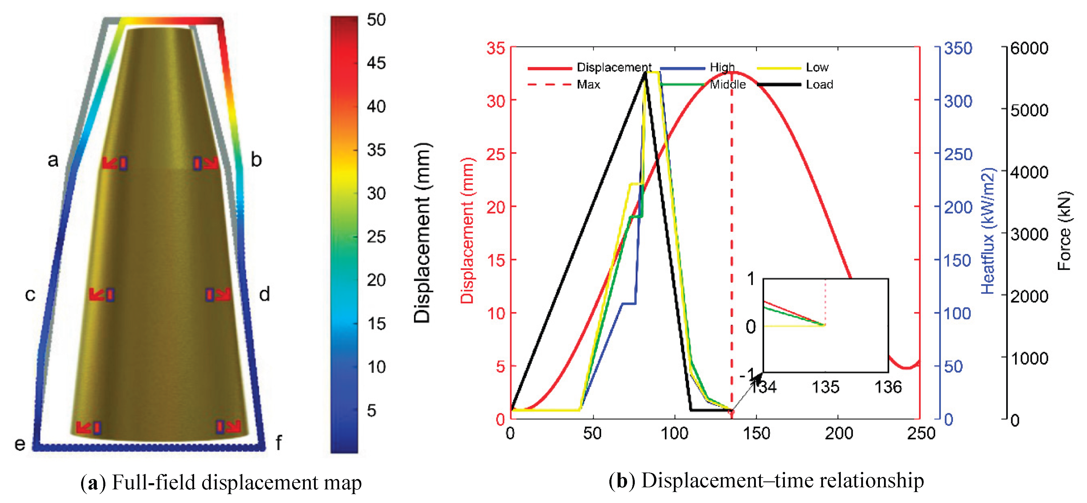

Table 1.
Critical node displacements of the PF.
| Point | Displacement/mm | Point | Displacement/mm |
| a | 19.719 | b | 27.307 |
| c | 6.533 | d | 9.442 |
| e | 1.158 | f | 1.910 |
Disclaimer/Publisher’s Note: The statements, opinions and data contained in all publications are solely those of the individual author(s) and contributor(s) and not of MDPI and/or the editor(s). MDPI and/or the editor(s) disclaim responsibility for any injury to people or property resulting from any ideas, methods, instructions or products referred to in the content. |
© 2025 by the authors. Licensee MDPI, Basel, Switzerland. This article is an open access article distributed under the terms and conditions of the Creative Commons Attribution (CC BY) license (https://creativecommons.org/licenses/by/4.0/).
Copyright: This open access article is published under a Creative Commons CC BY 4.0 license, which permit the free download, distribution, and reuse, provided that the author and preprint are cited in any reuse.


