Submitted:
11 December 2025
Posted:
12 December 2025
You are already at the latest version
Abstract
. This work studies relaxation processes and transient currents in a disordered multi-component LC system, consisting of inductive and capacitive reactances (non-dissipative elements). At first glance, relaxation processes seem impossible in non-dissipative systems such as LC systems. Nevertheless, at the percolation threshold, we obtain the exact solution for the multi-component system, consisting of two different types of inductors and two different capacitors with random displacement and connections. It was shown that the effective conductivity of such a non-dissipative disordered system has a real value. This means that relaxation and transient currents arise in this problem. The relaxation times for these processes are established for both low and high frequencies. A physical interpretation of the obtained results is given.
Keywords:
inductances
; capacitors
; dissipation
; relaxation time
; asymptpotics
; low frequences
; high frequences
1. Introduction
As is well known, the problem of relaxation and transient processes in conducting media is closely connected with the problem of the conductivity of the media [1,2,3], because the conductivity of a conducting medium
is determined by its relaxation time :
where and are the particle concentration and mass, respectively, and is an electric charge.
In the case of a disordered, multi-component LC system, which is composed of reactances from inductors and capacitors (non-dissipative elements) with random connections between them, it initially seems that no relaxation or transient processes are possible due to the non-dissipative character of the elements. Nevertheless, due to disorder in the system, caused by random placement and connections of reactances, finite dissipation arises at the percolation threshold. As a result, relaxation and transient processes appear in the LC systems.
To study this problem, the exact method developed in [4,5,6] was used. This method is based on the symmetry of two-dimensional equations relative to rotational or dual symmetry. Below we apply this method, which is described in the Appendix A in more detail, to calculate the effective conductivity of a discrete LC system consisting of randomly connected inductances and capacitances of two types with different values.
The paper is structured as follows. In Section 2 we calculate the effective conductivity of a disordered multi-component LC system. In Section 3 we study the transient currents at short and long times. Section 4 concludes the paper. The details of the calculations are provided in the Appendix A.
2. Effective Conductivity of Many-Phase System Consisting of Randomly Connected L and C at Percolation Threshold
Let us consider the conductivity of a four-component medium consisting of randomly placed inductors of two kinds and capacitors of two kinds (non-dissipative elements) with different values (a four-color chessboard) at equal concentrations of inductors and capacitors : .
At the percolation threshold we need to use the rotational transformations (A2) with coefficients . Therefore, according to formulae (A7) and (A8) the following expression for the effective conductivity is obtained:
The key feature of this solution is that the expression yields a real value. This result is unusual and interesting because a medium consisting of inductances and capacitances—elements with purely imaginary impedances—nevertheless exhibits a real effective conductivity at the percolation threshold. The analogous result was first obtained in [4], see also [6].
Let us analyze this formula (1) in the case when , and , . After some transformations, the following expression is obtained:
Here we introduce the following notations: and .
At low frequencies the following formula is obtained:
In the opposite case at high frequencies another expression is obtained:
And at intermediate frequencies the value depends on the relation between frequencies .
In the case we obtain from (2):
For clarity, these results are presented graphically in Figure 1.
In the opposite case we obtain from (2) – see Figure 2 as well:
3. Transient Currents in LC System
As is well known, in an LC system consisting of inductors (L) and capacitors (C), only oscillatory phenomena are possible. However, because a finite resistance exists in the investigated system at the percolation threshold – see formula (2), one can expect that transient currents and relaxation processes will appear:
Thus, the problem reduces to finding the value of the effective relaxation time . Let us study these currents in two limiting cases: at low and high frequencies, as described by the formulae (3) and (5).
In the system with inductance L and resistivity the relaxation time is equal to: ; in the system with capacitor C and the same effective resistivity R the relaxation time is equal to: . We therefore assume these quantities are equal within the system under investigation:
The exact relation between two effective characteristics and is obtained:
As a result, in the case of low frequencies we obtain:
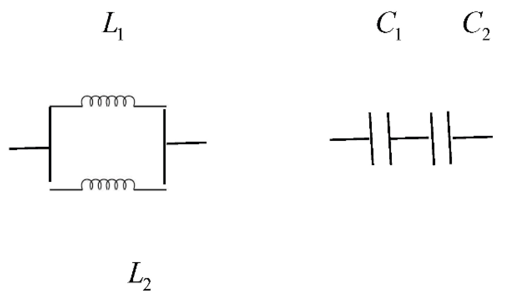
If we assume that at low frequencies the effective inductor is equal to , which means that the main current paths in the disordered system are provided by the series-connected inductors and the parallel-connected capacitors - see Figure 3
Thus, the effective relaxation time at low frequencies is:
And in the case of high frequencies , we obtain the following relation:
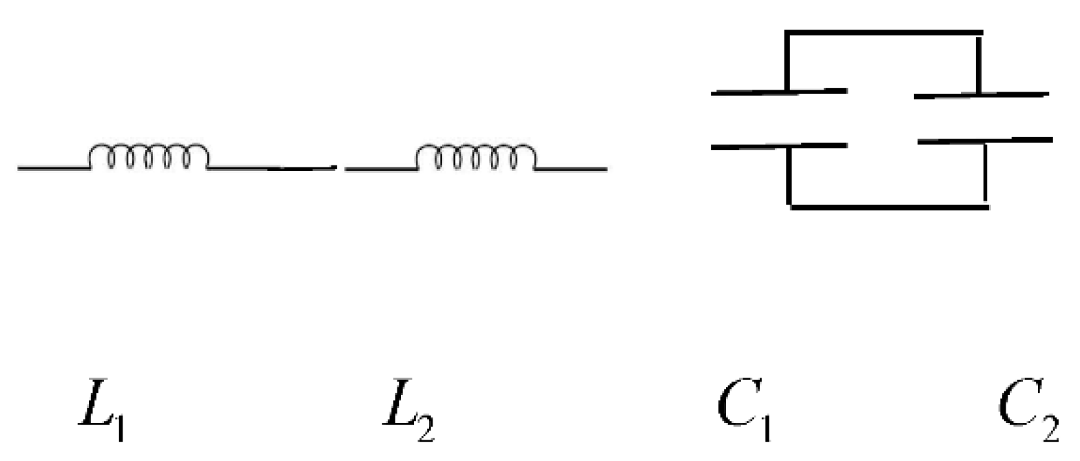
If we assume that at high frequencies the effective inductor is equal to , this means that in this limiting case (high frequencies) the main current paths in the disordered system are provided by the parallel-connected inductors and series-connected capacitors .
Figure 4.
The current paths are provided by inductors with parallel connection and by capacitors with series connection.
Figure 4.
The current paths are provided by inductors with parallel connection and by capacitors with series connection.
Thus, the effective relaxation time at high frequencies is:
It is easy to see that in the case of the two-component LC system, when and , the formulae (11) and (13) reduce to a single expression [3]:
4. Discussion
In this work, we have studied current flow in a two-dimensional system of randomly connected circuit elements. It has been shown that the effective conductivity is constant, i.e., independent of phase concentration, and is equal to either the capacitive reactance or the inductive reactance—see formula (3). However, at the point of the percolation transition, a finite effective resistance appears in a system of randomly connected circuits . The emergence of a dissipative state with finite resistance can be understood as follows. Suppose the initial phase through which the current flows consists of inductors; consequently, all the energy is concentrated in the inductive elements. In order for current to flow through another phase, the capacitive phase, it is necessary to transfer this energy to the capacitances, and for this it is necessary to excite local oscillations in the circuits, during which energy will be transferred from the inductors to the capacitances. In other words, the transition from one non-dissipative state of the system, described by conduction, to another non-dissipative state, described by a different value, is possible only through the excitation of the circuit, i.e., through the dissipative state at the point of topological transition. In our opinion, the obtained results can be used to study the properties of multi-component metamaterials.
Acknowledgments
I acknowledge prof. Dr. Ngo Son Tung and Prof. Dr Nguyen Xuan Sang for their support.
Conflicts of Interest
The authors declare no conflicts of interest.
Appendix A. The Exact Method for Studying Disordered Conducting Media: The Dykhne Approach
As is well known, a two-dimensional conducting medium is described by the DC equations and Ohm’s law:
where and are the local electric current and electric field, and is the conductivity of the medium. These equations have an internal symmetry – the invariance with respect to linear rotational transformations [6,7,8]:
Here is a unit vector normal to the plane.
In the general case of an anisotropic medium, for example, in a magnetic field, Ohm’s law has a tensor form:
Here is a two-dimensional conductivity tensor with components and . Therefore, in this case, to describe the dual symmetry of two-dimensional anisotropic media we use generalized linear transformations of rotation:
In the transformed system, primed Ohm’s law also has a tensor form. It is more convenient to reformulate the problem described above using complex variables with the imaginary unit as the local rotation by the angle . This means that we use the following notations:
and complex conductivity [9,10]:
After applying transformations (4), we obtain the relations between the components of the initial and primed systems in the general case:
In the case of capacitors and inductors:
Let us apply this method to study the multi-component disordered system, consisting of randomly connected inductances of two types L1, L2 and capacitances of two types C1, C2.
There are three possible transformations of the symmetry, according to permutations of the components of different types and the corresponding relations of duality for the effective conductivity [17].
1) First permutation symmetry of the system: an interchange of reactance components with odd and even numeration by positions:
2) The second symmetry of the system: an interchange of reactances with odd and even numeration in its positions and change of the direction of normal vector as:
3) The third symmetry of the system: the only change of the direction of normal vector as
Here, the coefficients are determined by the conditions (3).
In this case, the primed system is macroscopically equivalent to the original and as a result the effective conductivity is determined by the equation:
References
- Debye P.,1929. Polar Molecules. Chemical Catalog Company, New York.
- Douglas C. Giancoli, 1995,. Physics: Principles with Applications (4th ed.). London: Prentice Hall. ISBN 978-0-13-102153-2.
- Feymann lectures on physics. https://www.feynmanlectures.caltech.edu/.
- Berezinskii, V. L. (1971), “Destruction of long-range order in one-dimensional and two-dimensional systems having a continuous symmetry group I. Classical systems”, Sov. Phys. JETP, 1971, 32 (3), P. 493–500, Bibcode:1971JETP...32..493B.
- A. M. Dykhne, Conductivity of a Two-Dimensional Two-Phase System, JETP, 1970, Vol. 59, p. 110-113.
- A.M. Dykhne, Anomalous plasma resistance in a strong magnetic field, JETP, 1970, Vol. 59, pp. 641-647, 1970.
- V.E. Arkhincheev, On fixed points, invariants of Dykhne’s transformations and stability of solutions…, Letters to Journal of experimental and theoretical physics, 1998. V. 67. P. 951-958.
- M. Kosterlitz and D. Thouless, “Long Range Order and Metastability in Two-Dimensional Solids and Superfluids, Journal of Physics C: Solid State Physics, 1972, V. 5, Number 11, L124. [CrossRef]
- Kosterlitz, J. M.; Thouless, D. J. “Ordering, metastability and phase transitions in two-dimensional systems”. Journal of Physics C: Solid State Physics. 1972, 6 (7), P. 1181–1203. Bibcode:1973JPhC....6.1181K. [CrossRef]
- D. J. Thouless, Mahito Kohmoto, MP Nightingale, M Den Nijs, Quantized Hall Conductance in a Two-Dimensional Periodic Potential, Physical Review Letters, 1982, 49(6):405. [CrossRef]
- D. Khmeľnitskiĭ, Localization in a Field of a Two-Dimensional Random Potential, JETP Letters, 1983, Vol. 38, Issue 9, pp. 454-457.
- Shelby R. A., Smith D. R., Schultz, S., Experimental Verification of a Negative Index of Refraction. Science. 2001, 292 (5514): 77-79. [CrossRef]
- Pendry John B., Negative Refraction. Contemporary Physics. 2004, 45: 191–202. [CrossRef]
- V.G. Boltyanskki, V.A. Efremovich, Visual topology, Moscow: Science, 1982 (Kvant Library, Issue 21).
- V. I. Arnold, Topological invariants of algebraic functions. II, Function. Analysis and its Appendices, 1970, Volume 4, Issue 2, 1-9. [CrossRef]
- S.E.Korshunov, Topologic transitions in superconductors, Uspekhi fizicheskih nauk, 2006, 176 №3, P.233-272.
- D.J. Thouless, Quantization of particle transport, Phys. Rev. B, 1983, 27, 6083. [CrossRef]
- F.D.M. Haldane, Nonlinear Field Theory of Large-Spin Heisenberg Chains and Topologically Invariant ‘θ-Vacua, Phys. Rev. Lett., 1983, 50, 1153. [CrossRef]
- F.D.M. Haldane, Nonlinear Field Theory of Large-Spin Heisenberg Antiferromagnets: Semiclassically Quantized Solitons of the One-Dimensional Easy-Axis Néel State, Phys. Lett. A, 1983, 93, 464. [CrossRef]
- V.E. Arkhincheev, Quantum Hall effect in inhomogeneous media: Effective characteristics and local current distribution, Journal of experimental and theoretical physics, 2000, V. 118. P.465-474. [CrossRef]
Figure 1.
Dependence of the effective conductivity on the frequency.
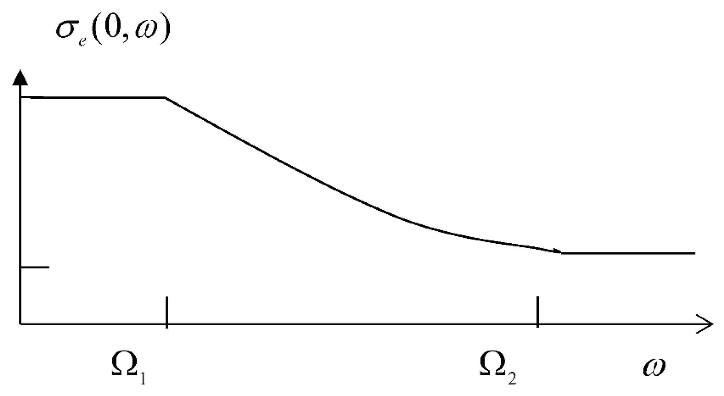
Figure 2.
Dependence of the effective conductivity on the frequency.
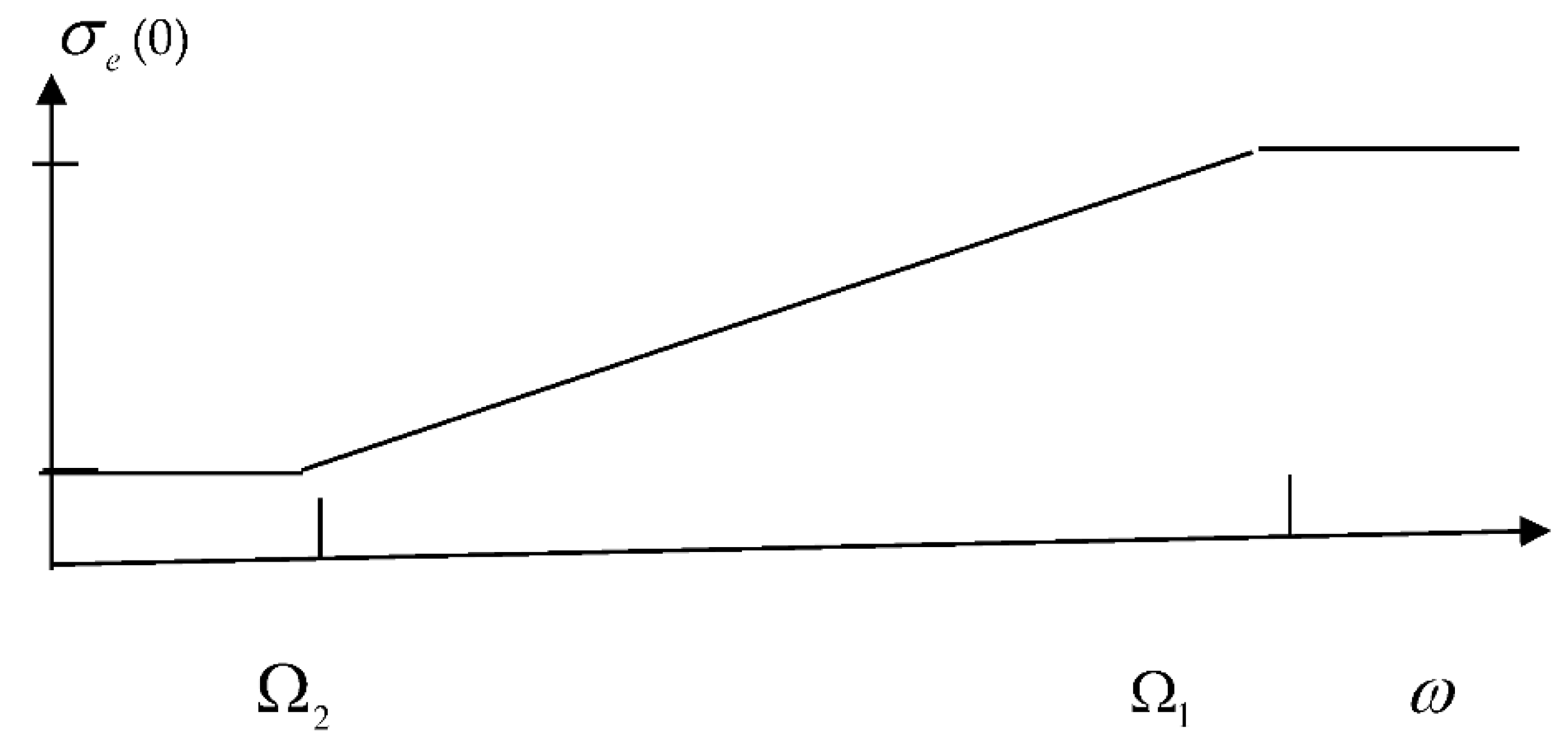
Figure 3.
The current paths are provided by series-connected inductors and by capacitors with parallel connection.
Figure 3.
The current paths are provided by series-connected inductors and by capacitors with parallel connection.
Disclaimer/Publisher’s Note: The statements, opinions and data contained in all publications are solely those of the individual author(s) and contributor(s) and not of MDPI and/or the editor(s). MDPI and/or the editor(s) disclaim responsibility for any injury to people or property resulting from any ideas, methods, instructions or products referred to in the content. |
© 2025 by the author. Licensee MDPI, Basel, Switzerland. This article is an open access article distributed under the terms and conditions of the Creative Commons Attribution (CC BY) license (http://creativecommons.org/licenses/by/4.0/).
Copyright: This open access article is published under a Creative Commons CC BY 4.0 license, which permit the free download, distribution, and reuse, provided that the author and preprint are cited in any reuse.


