
Submitted:
10 December 2025
Posted:
11 December 2025
You are already at the latest version
Abstract
Graphene (GRA) and graphene oxide (GO) have drawn significant attention in materials science, chemistry, and nanotechnology because of their tunable physicochemical properties and wide range of potential uses in biomedical and environmental applications. Building reliable, large-scale molecular models of GRA and GO is essential for molecular simulations of wetting, adsorption, and catalytic behavior. However, current methods often struggle to generate large, chemically consistent sheets at high oxidation levels. In addition, the resulting structures are frequently incompatible across different simulation packages. This work introduces a step-by-step protocol with custom Tool Command Language (Tcl) and modified Python scripts for building large-scale, AMBER-compatible GO structures with oxidation levels from 0% to 68%. The workflow applies a systematic surface modification strategy combined with post-processing and atom-type assignment routines to ensure chemical accuracy and force field consistency. The dataset includes fifteen MOL2 format files of 20 × 20 nm² GO sheets, ranging from pristine to highly oxidized surfaces, each validated through oxidation-ratio analysis and structural integrity checks. Together, the dataset and protocol provide a design of scalable and chemically reliable GO molecular models for molecular dynamics simulations.
Keywords:
graphene
; graphene oxide
; all-atom model
; mol2
; amber
; surface functionalization
; epoxy
; hydroxyl
; molecular dynamics simulation
1. Summary
Graphene oxide (GO) stands out as a practical and versatile alternative to pristine graphene because its surface is functionalized with oxygen-containing functional groups like hydroxyl, epoxy, and carboxyl groups. [1] These groups disrupt the perfect sp2 hybridized carbon network of graphene, increasing hydrophilicity, surface charge, and the ability to form hydrogen bonds, which enhances its dispersion in water and interactions with ions, polymers, and biomolecules. [2] At the molecular scale, the type and distribution of functional groups tune GO’s flexibility, reactivity, electronic properties, and sheet–sheet stacking behavior. [3] Another practical strength of GO is its scalability. Unlike pristine graphene, which is expensive and difficult to produce in large quantities, GO can be synthesized through oxidative intercalation and exfoliation of graphite using well-established methods that operate reliably at mass-production. [4] This combination of the low-cost synthesis, tunable structure, and chemistry of GO supports a wide range of uses from composite reinforcement and energy storage to pollutant adsorption, drug delivery, and the creation of hybrid materials.
Several automated GO-builder frameworks have recently been developed to address the difficulty of constructing oxidized graphene sheets with controlled functionality. For example, the MakeGraphitics [5] program provides an automated and experimentally validated way to build graphene-based structures by sequentially oxidizing graphitic lattices according to locally predicted reactivity, reproducing the experimentally observed two-phase morphology of oxidized and unoxidized domains rather than relying on random functional-group placement. [6] Released on Zenodo as a part of Sinclair and Coveney’s modeling workflow, it generates atomistic structures compatible with LAMMPS [7] and other MD engines using machine learning-derived reactivity rules. However, this package was written in Python 2 and depends on legacy libraries, leading to incompatibilities with the newer Python 3 environments and requiring manual patching or containerization to ensure reliable execution. GOPY [8] is another Python-based tool that rapidly generates 2D graphene-based models, including pristine graphene and several graphene derivatives, including graphene oxide, reduced graphene oxide, aminated polyethylene glycol functionalized reduced graphene oxide (rGO-PEG-NH2), and N-doped graphene (NG), in PDB format. Functional groups are added using simple geometric rules, allowing users to specify the number of carboxyl, epoxy, and hydroxyl groups for GO construction. Although GOPY generates these structures by placing functional groups onto a geometrically constructed basal lattice, its implementation is limited when systems become large. In our experience, GOPY’s coordinate-generation scheme can accumulate small numerical deviations across extended lattices, leading to misaligned atoms and incomplete bond recognition in downstream visualization software due to the absence of CONECT records in PDB files. In contrast, another tool called HierGO [9] employs a modular tiling algorithm that assembles large pristine and defective graphene regions from internally consistent sub-units, ensuring structural regularity even at tens of nanometers in size and enabling the incorporation of vacancies, holes, and topological defects with controlled spatial distributions. Although both GOPY and HierGO rely on geometry-based placement, we did not observe the drift or placement inconsistencies in HierGO that occurred with GOPY, even when generating large sheets from a single tile. HierGO’s implementation maintains consistent lattice geometry across extended domains and outputs structurally coherent PDB files and simulation-ready GROMACS files without the extensive post-processing required in our GOPY workflows. While these tools lower the barrier to constructing GO models, they ultimately generate their final structures in the PDB format, which is not directly compatible with AMBER and therefore requires substantial post-processing to assign atom types, bonds, residues, and charge models in a force-field-consistent manner. Moreover, existing builders typically target specific force fields (e.g., OPLS or ReaxFF) or provide code without a curated, simulation-ready dataset covering a systematic range of oxidation states, leaving a gap for workflows that demand fully parameterized, immediately usable GO models.
This work presents a reproducible dataset and a complete computational protocol for generating chemically homogeneous GO structures compatible with the AMBER [10] molecular dynamics simulation package. This workflow integrates the HierGO [9] suite for oxidation pattern generation with BIOVIA Discovery Studio (DS) visualizer [11] and Visual Molecular Dynamics (VMD) [12] for structure refinement, atom typing, and parameterization. The curated dataset comprises 15 GO systems spanning oxidation levels from 0% to 68% validated through carbon to oxygen (C:O) ratio analysis and atom-type counting scripts. The resulting Tripos MOL2 files include General AMBER Force Field (GAFF)-compatible atom types and are ready for simulation setup. Details on why GAFF was used are described in the document titled Building AMBER Compatible Graphene Oxide Tutorial provided with the dataset [13]. The provided Python and Tool Command Language (Tcl) scripts automated key stages such as oxidation generation, topological correction, residue assignment, and validation. This enabled consistent and scalable preparation of oxidized graphene systems. All files, scripts, and a complete step-by-step tutorial were made available.
2. Data Description
The dataset comprises fifteen GO structures at specified oxidation targets of 0, 5, 10, 15, 20, 25, 30, 35, 40, 45, 50, 55, 60, 65, and 68%. Each structure is provided as an AMBER-ready Tripos MOL2 file derived from a single, non-periodic graphene sheet approximately 20 × 20 nm² in size. The sheet was generated by repeating the graphene unit cell to an integer number of rings such that no bonds cross a periodic boundary, as AMBER does not support bonds across periodic boundaries. Oxidation was applied directly to this pristine sheet rather than by stitching smaller tiles, ensuring structural continuity and avoiding junction artifacts.
Each oxidation level is represented by a single file named x_GOyy_final.mol2 (where x indicates the file order and yy indicates the specified O%). The complete protocol is detailed in Figure 1 and in the tutorial document provided with the dataset. [13]
Figure 1 above, shows detailed pipeline from pristine graphene tile creation to oxidation, error handling, and post-processing (cleaning, typing, and composition checks). The decision flow shows (i) tile creation (create-tile.py), (ii) oxidation (decorate-tile.py), (iii) fallback to decorate-tile_modified.py if persistent placement errors occur, and (iv) post-processing in DS Visualizer and VMD with custom Tcl/Python scripts to finalize MOL2 and frcmod files. We generated ∼20 × 20 nm² GRA tiles using create-tile.py, then applied target oxygen coverages (O/C) using decorate-tile.py at a “fresh” ratio of 2:1. When epoxy placement failures persisted at higher O% targets, we invoked decorate-tile_modified.py (same inputs) to complete functionalization. Structures were opened in DS Visualizer to remove loose/dangling atoms, then converted to MOL2 in VMD. We assigned atom types/charges with 1_GO_atom_info_assignment.tcl, validated counts quantitatively with 2_atom_type_counter.tcl and 3_C:O_ratio.tcl, followed by visualization with 4_snapshot.tcl, and produced final substructures with 5_mol2_substruct_numpy.py to obtain GRA/GO as an AMBER-compatible MOL2 file.
This final MOL2 file contains the complete atom, bond, and substructure records needed for the direct import into topology builders. Intermediate files are also provided for transparency and follow a numeric prefix (x) corresponding to the processing stage (for example, a cleaned pre-typing PDB, an unedited MOL2 after oxidation, or an edited MOL2 before substructure rebuild). The x_GOyy_final.mol2 files follow the Tripos specification with GAFF-compatible atom types and a rebuilt @<TRIPOS>SUBSTRUCTURE section. Atom records include atom name, Cartesian coordinates, atom type, formal charge, and residue assignment and bond records define connectivity and bond orders. The SUBSTRUCTURE block lists residue names and sequential residue IDs that encode the chemical semantics for analysis. Residues are categorized as basal graphene carbons (GRA), hydroxyl groups (OH), and epoxy bridges (EPX). The atom typing scheme employs a minimal GAFF mapping where aromatic sp2 carbons are labeled ca; oxidized sp3 carbons are c3; hydroxyl oxygens are oh; epoxy oxygens are os; and hydroxyl hydrogens are ho. This limited vocabulary simplifies comparison between models and maintains consistency across oxidation levels. The final MOL2 files preserve these labels for efficient selection of atom or residue types.
Table 1 shown below details oxidation rates and the corresponding C:O (to have comparisons with experimental elemental analysis studies) and modified-carbon ratios, as well as total number of atoms per model as it is relevant information for molecular dynamics simulations. The specified oxidation percentage (Overall Modification % in Table 1) is calculated as 100 * NO / NC, where NO and NC are the number of oxygen and carbon atoms in the final structure. The C:O ratio is NC / NO and is expressed as X:1; numerically, this equals 100 / O% under the same definition. The “Modified carbon %” is given by 100 * Nc3 / (Nca + Nc3) and represents the proportion of carbons that rehybridize to sp3. For the “fresh” 2:1 hydroxyl: epoxy placement, a first-order approximation is Modified carbon % ≈ (4/3) * O%, since each epoxy oxygen converts two carbons while each hydroxyl converts one. At higher oxidation, achievable epoxy placements are limited, leading to an expected hydroxyl bias. The atom-type count report lists Nca, Nc3, Noh, Nos, and Nho. From these, the composition script computes NC = Nca + Nc3 and NO = Noh + Nos, then outputs NC / NO as the C:O ratio and 100 * NO / NC as the “Overall Modification %.” The modified-carbon percentage is derived as 100 * Nc3 / (Nca + Nc3). For example, the GO20 model shows C:O ≈ 5.0:1 and Modified carbon ≈ 26.7%. Minor deviations at high oxidation (GO60 and above) are expected and explicitly reported. Figure 2 highlights the distribution of GRA, OH, and EPX regions, revealing local clustering relevant to surface wetting and adsorption analyses.
3. Methods
The workflow proceeds in five stages that collectively generate AMBER-compatible GO structures at specified oxidation levels while maintaining a single, coherent sheet topology and consistent atom typing. The first stage constructs a non-periodic graphene tile with lateral dimensions near 20 × 20 nm², chosen to balance realistic interfacial length scales with tractable atom counts for routine simulations. The tile is saved as a PDB for portability and to enable downstream cleaning operations that remove hanging atoms at edges and ensure that the resulting structure reloads as a single fragment.
The second stage applies oxygen functionalization to reach the desired specified coverage. Hydroxyl and epoxy groups are placed with an intended “fresh” ratio of approximately two hydroxyls per epoxy, which promotes a realistic mixture of single-carbon and bridging modifications across the basal plane. At moderate oxidation levels, the standard decoration routine achieves the requested placements with high fidelity. As the target coverage increases toward 60% and beyond, epoxy placement attempts can fail because suitable neighboring pairs become rare on a finite lattice. To address this, during the decoration step, epoxy placement attempts are ignored to prioritize as much hydroxyl placement as possible. This improves the coverage without leaving the sheet under-functionalized. However, this robustness comes at the cost of large hydroxyl bias at the highest coverages, which we make explicit during validation.
The third stage encompasses cleaning and export. The decorated PDB is inspected to remove dangling fragments and to correct any spurious edge hydrogens or atypical valences introduced during aggressive high-coverage placement. The cleaned sheet is then exported to MOL2 so that atom typing and residue assignment can be applied consistently in a single file format widely supported in the AMBER ecosystem. Care is taken to preserve connectivity, so the entire sheet remains one molecular fragment; this is important for later parameterization and to avoid unintended fragmentation at the topology-building step.
The fourth stage assigns residues and GAFF-compatible atom types. Basal carbons retain an aromatic sp² type, oxidized carbons are converted to sp³ as appropriate, oxygen atoms are labeled according to their role in hydroxyl or epoxy groups, and hydroxyl hydrogens are explicitly typed. At this step, partial charges may be assigned according to a consistent scheme suitable for large sheets. The assignment script also performs sanity checks, such as detecting the rare but possible case in which a carbon has been targeted both by hydroxyl and epoxy routines. The output of this stage is a MOL2 file in which residue names (e.g., GRA, OH, and EPX) and GAFF atom types (ca, c3, oh, os, and ho) encode the chemical semantics needed by the force field.
The fifth stage validates and finalizes the structures. Automated counting scripts tabulate atom-type populations, from which the oxidation percentage and C:O ratio is computed as NC, NO, and their ratio. A separate report computes the modified-carbon percentage directly from the c3 and ca counts. Snapshot scripts render color-coded images that provide rapid visual assessment of functional-group distribution and help identify any nonuniformities or artifacts that merit a return to cleaning. Finally, a substructure-rebuild utility regenerates the MOL2 SUBSTRUCTURE section to ensure that residues are numbered sequentially and that the file is well-formed for use in topology builders. The final deliverables are saved as GOxx_final.mol2, and the corresponding text reports and images are archived with the same base name for traceability.
4. Limitations and Reasonings
Data quality control centers on predictable failure modes and their remedies. At the highest oxidation levels, achievable epoxy placement can be limited, and a bias toward hydroxyl groups is expected. This effect is recorded rather than hidden; each final model comes with its achieved composition so that simulation studies can reference the actual hydroxyl-to-epoxy balance. Additional failure modes include lingering edge artifacts and occasional mis-typed carbons if cleaning is skipped. The curation protocol requires repeating the cleaning and assignment stages until validation reports contain no warnings. Reproducibility is supported by consistent file naming, versioned scripts, and inclusion of representative logs showing command lines and console outputs for low, mid, and high oxidation cases.
Further limitation occurs when these GO surfaces are used alongside biomolecules. Default atom and residue names can cause GO sheets to be misidentified as a protein in VMD or AMBER/LEaP, leading to incorrect selections, residue merging, or connect0/connect1 errors. To avoid this, the entire sheet should be assigned a single residue (e.g., GRO) with a unified residue ID, and atom names should be adjusted to avoid overlap with common biomolecular atom names. Although the default models are adequate for surface–water simulations, users integrating GO with biomolecular systems should apply this renaming procedure by reassigning atom and residue labels in the final .mol2 file.
5. User Notes
Further notes on the usage of the dataset will help other researchers quickly begin working with the models. Users are encouraged to consult the accompanying tutorial document, which provides a step-by-step workflow with checklists, figures, and detailed explanations that make the procedures easier to digest and reproduce.
Author Contributions
Conceptualization, M.F.; methodology, M.F.; software, M.F.; validation, M.F. and A.L.K.; formal analysis, M.F. and A.L.K.; investigation, M.F. and A.L.K.; resources, M.F.; data curation, M.F.; writing—original draft preparation, M.F.; writing—review and editing, M.F., A.L.K., and Y.G.Y.; visualization, M.F.; supervision, Y.G.Y.; project administration, Y.G.Y.; funding acquisition, Y.G.Y. All authors have read and agreed to the published version of the manuscript.
Funding
This work was made possible by funding from the Novo Nordisk Foundation (grant NNF22SA0078767).
Institutional Review Board Statement
Not applicable
Informed Consent Statement
Not applicable
Data Availability Statement
All data are available at Zenodo and GitHub. Zenodo DOI: https://doi.org/10.5281/zenodo.17863270. Github Repository: https://github.com/yingling-group/AmberGO
Acknowledgments
We thank NNF and Biocatalyst Interactions with Gasses (BIG) collaboration for their support. In addition, we thank group alumni Dr. James Peerless for his substructure Python script and Dr. Hoshin Kim for his graphene oxide frcmod file.
Conflicts of Interest
Authors declare no conflicts of interest.
Abbreviations
The following abbreviations are used in this manuscript:
| AMBER | Assisted Model Building with Energy Refinement |
| DS Visualizer | Discovery Studio Visualizer |
| EPX | Epoxy |
| GAFF | General AMBER Force Field |
| GO | Graphene oxide |
| GRA | Graphene |
| HierGO | Hierarchical Graphene Oxide |
| LAMMPS | Large-scale Atomic/Molecular Massively Parallel Simulator |
| OH | Hydroxyl |
| OPLS | Optimized Potentials for Liquid Simulations |
| PDB | Protein Data Bank |
| ReaxFF | Reactive Force Field |
| VMD | Visual Molecular Dynamics |
References
- Zhan, M.; Xu, M.; Lin, W.; He, H.; He, C. Graphene Oxide Research: Current Developments and Future Directions. Nanomaterials 2025, 15, 507. [Google Scholar] [CrossRef] [PubMed]
- Zhang, Y.; Wu, C.; Guo, S.; Zhang, J. Interactions of Graphene and Graphene Oxide with Proteins and Peptides. Nanotechnology Reviews 2013, 2, 27–45. [Google Scholar] [CrossRef]
- Yang, J.; Shi, G.; Tu, Y.; Fang, H. High Correlation between Oxidation Loci on Graphene Oxide. Angew Chem Int Ed 2014, 53, 10190–10194. [Google Scholar] [CrossRef] [PubMed]
- Pei, S.; Cheng, H.-M. The Reduction of Graphene Oxide. Carbon 2012, 50, 3210–3228. [Google Scholar] [CrossRef]
- velocirobbie Velocirobbie/Make-Graphitics v0.1.0 2019.
- Sinclair, R.C.; Coveney, P.V. Modeling Nanostructure in Graphene Oxide: Inhomogeneity and the Percolation Threshold. J. Chem. Inf. Model. 2019, 59, 2741–2745. [Google Scholar] [CrossRef] [PubMed]
- Thompson, A.P.; Aktulga, H.M.; Berger, R.; Bolintineanu, D.S.; Brown, W.M.; Crozier, P.S.; Veld, P.J.; Kohlmeyer, A.; Moore, S.G.; Nguyen, T.D.; et al. LAMMPS - a Flexible Simulation Tool for Particle-Based Materials Modeling at the Atomic, Meso, and Continuum Scales. Computer Physics Communications 2022, 271, 108171. [Google Scholar] [CrossRef]
- Muraru, S.; Burns, J.S.; Ionita, M. GOPY: A Tool for Building 2D Graphene-Based Computational Models. SoftwareX 2020, 12, 100586. [Google Scholar] [CrossRef]
- Garcia, N.A.; Awuah, J.B.; Zhao, C.; Vuković, F.; Walsh, T.R. Simulation-Ready Graphene Oxide Structures with Hierarchical Complexity: A Modular Tiling Strategy. 2D Mater. 2023, 10, 025007. [Google Scholar] [CrossRef]
- Case, D.A.; Cerutti, D.S.; Cruzeiro, V.W.D.; Darden, T.A.; Duke, R.E.; Ghazimirsaeed, M.; Giambaşu, G.M.; Giese, T.J.; Götz, A.W.; Harris, J.A.; et al. Recent Developments in Amber Biomolecular Simulations. J. Chem. Inf. Model. 2025, 65, 7835–7843. [Google Scholar] [CrossRef] [PubMed]
- BIOVIA Discovery Studio Visualizer. 2024.
- Humphrey, W.; Dalke, A.; Schulten, K. VMD – Visual Molecular Dynamics. Journal of Molecular Graphics 1996, 14, 33–38. [Google Scholar] [CrossRef] [PubMed]
- Fedai, M. Yingling-Group/AmberGO: AmberGO Version 1 (v1.0). 2025. [Google Scholar]
Figure 1.
Overview of the generation and post-processing workflow leading to the final model’s files. Created in Part with Biorender.com. Fedai, M. (2025) https://BioRender.com/i63ehid.
Figure 1.
Overview of the generation and post-processing workflow leading to the final model’s files. Created in Part with Biorender.com. Fedai, M. (2025) https://BioRender.com/i63ehid.
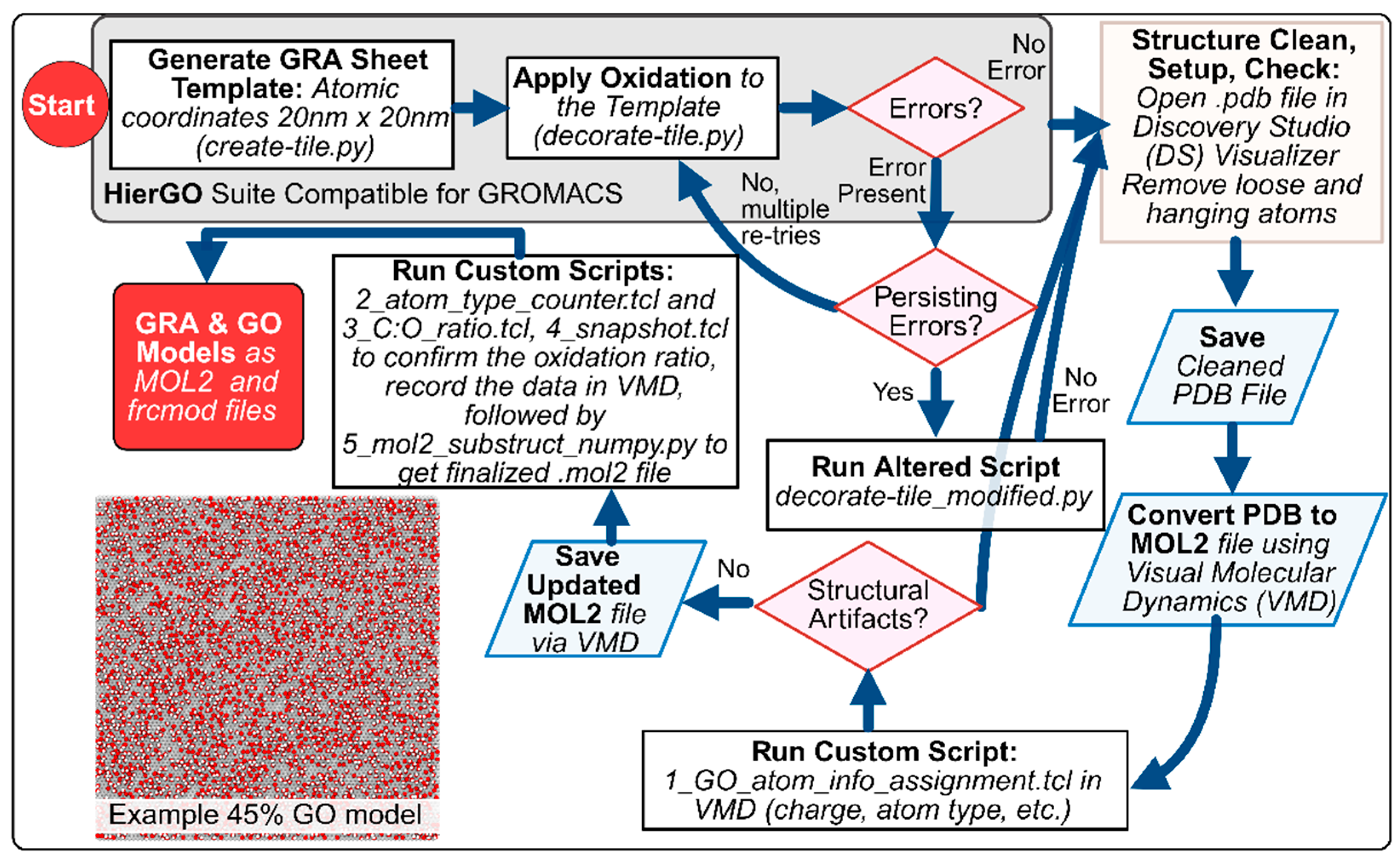
Figure 2.
Visual representation of the GO surface models. Unmodified carbons are shown as black outlines on the hexagonal lattice; fully unmodified aromatic rings are highlighted with a red fill. Carbons functionalized with epoxy groups are colored orange, and those bearing hydroxyl groups are colored purple. All renderings were generated using the 4_snapshot.tcl script in VMD. A corresponding small-scale view of this scheme is also provided within tutorial document.
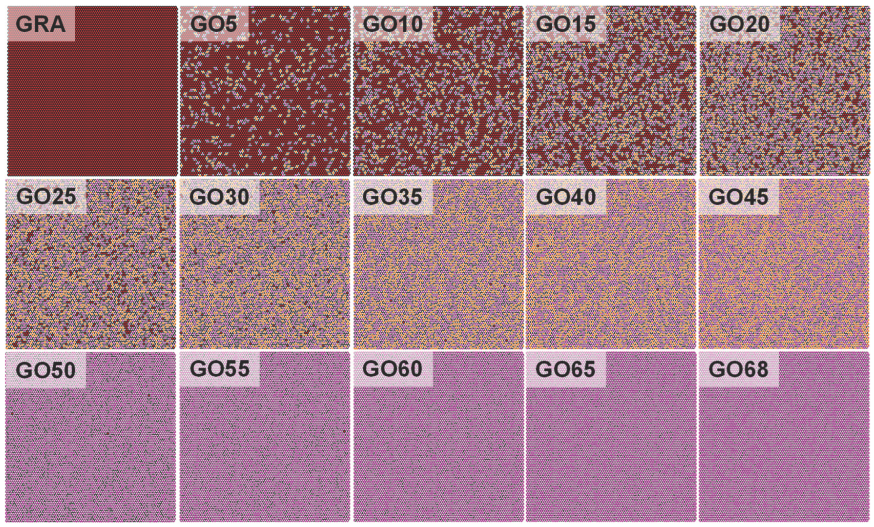

Table 1.
GO Models Oxidation and Composition Summary.
| Model | Overall Modification % |
C:O Ratio | Modified Carbon % | Total # of Atoms for Surface Model |
|---|---|---|---|---|
| GRA | 0 | n/a | 0 | 15226 |
| GO5 | 5 | 20.01:1 | 6.7 | 16495 |
| GO10 | 10 | 10:1 | 13.3 | 17763 |
| GO15 | 15 | 6.67:1 | 20.0 | 19031 |
| GO20 | 20 | 5.00:1 | 26.7 | 20301 |
| GO25 | 25 | 4.00:1 | 33.3 | 21570 |
| GO30 | 30 | 3.33:1 | 40.0 | 22838 |
| GO35 | 35 | 2.86:1 | 46.7 | 24108 |
| GO40 | 40 | 2.50:1 | 53.3 | 25376 |
| GO45 | 45 | 2.22:1 | 59.9 | 26659 |
| GO50 | 50 | 2.00:1 | 50.0 | 30452 |
| GO55 | 55 | 1.82:1 | 55.0 | 31974 |
| GO60 | 60 | 1.67:1 | 60.0 | 33496 |
| GO65 | 65 | 1.54:1 | 65.0 | 35018 |
| GO68 | 68 | 1.471 | 68.0 | 35932 |
1 C:O Ratio calculated by (ca+c3)/(oh+os). 2 Modified carbon percentage (%) calculated by number of modified carbon (c3) divided by number of all carbon (ca /c3).
Disclaimer/Publisher’s Note: The statements, opinions and data contained in all publications are solely those of the individual author(s) and contributor(s) and not of MDPI and/or the editor(s). MDPI and/or the editor(s) disclaim responsibility for any injury to people or property resulting from any ideas, methods, instructions or products referred to in the content. |
© 2025 by the authors. Licensee MDPI, Basel, Switzerland. This article is an open access article distributed under the terms and conditions of the Creative Commons Attribution (CC BY) license (http://creativecommons.org/licenses/by/4.0/).
Copyright: This open access article is published under a Creative Commons CC BY 4.0 license, which permit the free download, distribution, and reuse, provided that the author and preprint are cited in any reuse.


