1. Introduction
Polyurethane (PU) foams are versatile class of polymeric materials where the tunable cellular structure and the combination of soft and hard segments form soft and rigid polymers with a different degree of microphase-separated structure. Thanks to this unique microstructure, PU exhibits a wide range of physical and mechanical properties, making it suitable for various applications in construction, transportation, household, military and many other fields [
1,
2,
3,
4,
5]. For this versatility PU has been recognized as the “fifth-largest plastics”[
6], due to its widespread and diverse applications, encompassing a vast range of products from everyday items of daily use, such as shoes, clothes, sport equipment’s, cars component, furniture and mattresses. Its high versatility, combined with properties like durability, resilience, and flexibility, makes it a staple in many industries [
7,
8,
9,
10,
11,
12]. In this context, the increasing quantity of PU wastes, very long lifetimes, due to their high durability and resistance toward solvents and compounds, and their long persistence in the environment make the PU wastes recycling an urgent task. Therefore, the end-of-life recovery and recycling of PU are currently of extreme importance avoiding landfill confinement or incineration for the toxicity originating during the combustion process. In addition, the recycling strategies of PU are in line with the reduction of crude oils (i.e. fossil fuels), which are widely used for the synthesis of PU [
13]. Four major methods are used for PU recycling and recovery: mechanical recycling, advanced chemical and thermochemical recycling, energy recovery and product recycling [
13,
14]. However, each of these methods provides advantages and disadvantages and the choice of the most suitable procedure of recycling should be considered case-by-case, based on the specific details of each situation and in particular taking into consideration the economic, logistical and ecological aspects.
With regard to mechanical recycling, fragmentation of PU wastes by grinding PU into fine particles (powder) is considered one of the most effective method [
15]. PU wastes, derived by appliances, automobiles, bedding, carpet cushion, upholstered furniture and other consumer products, parts of old components of refrigerators, can be processed as sawdust or ground into a fine powder. Grinding is most frequently carried out in tumbling mills such as ball and rod mills, utilizing loose grinding media, lifted by the rotation of the drum, to break the ores in various combinations of impact, attrition and abrasion to produce the specified product. The resulting polymer microstructures can be re-used in several applications spanning from the fabrication of rigid components, such as motor and pump cover, by compression and thermal treatment (350 bar and 180°C), to fillers for other resins and re-bonding with adhesives [
16], as well as for oil sorption and oil spill cleanup [
17].
In particular, in the field of oil sorption application, PU foams were employed for applications as absorbents for oil spill treatment showing an intrinsic high sorption capacity in imbibing organic solvents and oils [
18,
19,
20,
21,
22,
23,
24,
25,
26,
27,
28]. In fact, thanks to their hydrophobic nature and the high affinity with different types of hydrocarbons, PU foams can reach to selectively absorb an amount of oil even until 10 times higher than their original weight, without sinking over the sea [
29]. However, while PU foams have been extensively investigated for these applications, no other work was reported, to the best of our knowledge, on the specific investigation of oil sorption capacity and absorbing mechanism of PU powder from grinding of PU wastes. Some studies reported an increase or modification in the surface area resulting from the disruption of the closed cells,[
30,
31], nevertheless, little is known about the internal arrangements to which the polymeric matrix may possibly undergo upon mechanochemical activation, and how the mechanical treatment can induce structural and chemical modifications on PU structures and consequently affect the oil sorption capacity.
In this context, we aim to investigate the possible relation between the changes in the structural and morphological properties in BMG-PU powders induced by mechanical treatment and their oil sorption capability. For this purpose, we took into consideration several types of PU foam and the corresponding BMG-PU powders with two different particle dimensions obtained by blade milling of wasted PU-based products including seats, mattresses, side panel of cars, packing components, insulating boards for refrigerators and freezers. To investigate the effect of the mechanical action a complete structural and morphological characterization of the PU foam wastes, both soft and rigid, before and after blade-milling process has been carried out. In particular, optical and morphological studies was used to analyze the macroscopic modifications with the rupture of the PU cells into fragmented structures of different size and shape, whereas structural rearrangement and microphase separation between the hard and soft domains were highlighted by combining spectroscopic techniques with morphological and thermal analysis.
The differences in oil sorption capacity between the PU foams and blade milled ground (BMG) PU powders with intermediate particle size (1 mm –250 μm) and the finest fraction (250 μm – 5 μm) were then analyzed, correlating structural and microphase changes with the increase of surface reactivity and contact area between oil and polymer structures. These absorbing BMG-PUs can thus represent an alternative solution for effective oil sorption and eventually of oil spill cleanup making at the same time more sustainable and less expensive the management of PU waste materials.
2. Experiment
PU foams were recovered from a Rome’s waste collection center and at the Auto Breaker Pomili Srl (Monterotondo, Rome, IT) specialized in the disposal and recycling of wasted materials from the dismantling of house refrigerators, insulating components for buildings, and vehicles, respectively. Specifically, in the case of refrigerators to obtain the recycled PU materials, several starting treatments were carried out in the center prior collecting and grinding, i.e the initial disassembling of the electrical components, the depollution of hazardous fluids and refrigerants, the extraction of compressor, and the shredding of exterior shell and inner plastic unit of refrigerators. Then, the mixed plastics were processed in another plant, while the ferrous and non-ferrous metal fractions were recovered through magnetic separator by electric arc furnace and eddy current separator, respectively. Before magnetic separation, the heterogeneous material resulting from the shredding phase is subjected to air separation in a “ zig-zag” separator unit obtaining PU foams (> 1cm; 1 cm - 7 cm) for about 21.7% of the total mass. Finally, the PU foams are treated by milling process to achieve particle size below 10 mm (1 cm) and then briquetted and sent to incineration. In this study we collected pieces of PU foams obtained after zig zag separation (> 1cm; 1 cm - 7 cm).
For both PU originating from insulating components (refrigerators) and vehicles the PU foams with dimensions ranging between 1 and 5 cm were collected and ground in a blade mill. Laboratory knife mill Polymix PX-MFC 90 D (Kinematica AG, Malters, Switzerland) was used for the experiment. Three knife mills can operate at constant revolutions 900 min−1 with diameter of the chamber 150 mm. Pieces of PU foams were put in the feeding chamber of the mill manually and about 50 gr of PU powder is obtained after 5 min. To optimize the grinding process of soft PU with the aim of obtaining powder of smaller size the samples were immersed in a nitrogen liquid bath and then pulverized by blade milling. Differently, blade milling of rigid PU foams was performed on pre-cut PU foam pieces at ambient temperature. In terms of grinding yields, the rigid PU foam yielded approximately between 65–80% of material below 1 mm, with 20–35% falling into the finest fraction (< 250 µm). On the other hand in case of soft PU foams, less than 10–15% reached the 750- 500 µm fraction, and most part of the materials remained in the 1mm -750 µm dimensional range. For this reason we treated the soft PU foams with liquid nitrogen prior milling with the aim of increasing in fine-particle yield. Under identical milling and sieving conditions, the mass fraction passing 500 µm increased to 55%, while particle fraction below 250 µm increased to about 40 %. (see Table S1). All yields are averages of three independent runs. The particle size distributions of the BMG-PU ranging from 0.5 to 2,000 μm were determined for both dry (air) and wet (water) particles by laser diffraction using a Mastersizer 2000 equipped with a Hydro 2000 (Malvern Panalytical Ltd, Malvern, UK). A single measurement of size distribution consisted of 15 repetitions lasting for over 10 s, taken at millisecond intervals. Optical images of ground particles were obtained with a Malvern Morphology G3 apparatus equipped with a Nikon CFI 60 optical unit and a CCD digital camera. This system allowed to get reliable information on the size and shape of PU particles from 0.5 μm to several millimeters as it was able to analyse a statistically significant number of particles. Finally, three stainless sieves with 18, 60 and 3250 meshes were used to separate powder having dimensions of about 1 mm, 250 μm and 5μm. Each fraction was collected separately, weighed, and its yield expressed as a percentage of the total mass input.
Scanning electron microscopy (SEM) images of the PU foams and BMG-PU materials were acquired using a GEMINI-Supra 40 from Carl Zeiss (Oberkoken, Germany) with acceleration voltages ranging from 1 to 15 kV. AFM images were performed in tapping mode using a Scanning Probe Microscope from Digital Instruments (Veeco, Santa Barbara, CA-USA) with Nanosensor TESP (tapping etched silicon probe) type single beam cantilevers. These cantilevers have a nominal length of ca. 125-µm with force constants in the range of 20-100N/m and were used at oscillation frequencies in the range of 200 and 400 kHz. The cantilevers had a very small tip radius of 5 - 10 nm. All images were obtained in air and collected over a range of scan sizes from 10 µm to 500 nm, depending on the particles analyzed. The BMG-PU powder was directly inserted in the AFM sample holder using a double-sided adhesive tape.
Solid-state NMR measurements were carried out with a Bruker Avance 400 spectrometer containing 5 mm inverse detection z-gradient probe. The 13C NMR spectra at 9000 Hz were performed at 25 °C using deuterated dimethyl sulfoxide (DMSO-d6) as solvent. Signals of carbon atoms are given on the δ scale relative to the signals from DMSO-d6 .
X-ray diffraction (XRD) patterns were collected using a Rigaku Rint 1200 (Rigaku, Tokyo, Japan) equipped with a Cu Kα radiation. The diffracted X-rays were detected using a NaI(Tl) scintillation counter point detector coupled with a graphite monochromator positioned in the diffracted beam.FTIR spectra were obtained using a VARIAN 1000 FTIR Scimitar Series spectrometer (Varian Inc., USA). Samples were prepared by mixing PU materials with KBr at ratio of 1:100 w/w and pressing the resulting mixtures into cylindrical wafers. Thermogravimetric analysis (TGA) and differential thermal analysis (DTA) were performed using TA Instruments SDT-Q600 equipment (New Castle, DE, USA) in the temperature range from 25°C to 800°C with a heating rate of 10°C min-1.
The study of oil sorption was conducted on waste PU foams and two particle-size fractions deriving from the pre-treatment and grinding process. The tests were carried out three times each to ensure accuracy and reproducibility on the basis of the procedures outlined in the international ASTM F726–17 standard method, which is used for evaluating the capability and performance of sorbents in removing crude oils and related spills [
34].
The oil sorption capacity was assessed according to the formula:
where:S
s is the oil sorption capacity; W
fis the weight of the sorbent at the end of oil test after 2 min dripping; W
i is the initial weight of the dry sorbent.
Specifically, the oil sorption capacity represents the amount of sorbed oil normalized by the absorbent’s mass. In this work, a diesel fuel (Quaser, produced by Q8) with a density of 0.845 and a kinematic viscosity of 3.9 mm2/s was used for oil sorption tests. The laboratory equipment consists of a cristallyzer, a steel mesh of 0.1 mm and an analytical balance. The procedure for the sorption tests is detailed as follows: the PU sample was placed in the steel mesh basket (0.1 mm mesh) and kept in contact with the oil poured in the crystallizing dish (2.5 cm height) for 15 min. After this period the sample was removed from the crystallizer and the soaked absorbent with the mesh basket was drained for 10 min allowing the release of the oil in excess which is not completely absorbed. The weight measurements of the samples were taken after 0.5, 1, 2, 3, 5, 10, 15, 20, 25, 30, 45, 60 and 300 min in order to evaluate accurately the sorption capacity and the tendency to release.
3. Results and Discussion
3.1. Recycle of Dismantled PU Foams and Mechanical Treatment by Blade-Milling Process: Analysis of Size, Morphology and Chemico-Physical Properties
Prior to mechanical treatment, rigid and soft PU foams were manually disassembled from end-of-life refrigerators and vehicle components, respectively, both at waste disposal centers and in the laboratory. As evident from
Figure 1a-c, this straightforward procedure enabled the recovery of PU foams in in medium to large sizes, and subsequently cut into small pieces of 5–7 cm.
Each type of PU foam, derived from different end-of-life products, was milled separately in order to preserve the characteristics of the individual materials and for oil sorption tests. At the same time, mixed soft PU foams originating from various flexible products, including packing materials and vehicle components, such as car seats, steering wheels, and headrests, were collected and processed by blade milling. In both cases, BMG-PU powders with various particle size and size distributions were obtained, as clearly shown by laser diffraction analysis (
Figure 2a). Data essentially indicated that the first mechanical fragmentation in the blade mill consisted in particles with wide size, ranging between 2 μm to 1.500-2.000μm (2 mm), with a broad, unimodal distribution centred at about 150 µm. Specifically, the volume of over 95% of the entire particle population into the particle size range below 1000 μm, with mean values of 133 μm. The analysis was also performed for wet particles (water) (see Figure S1), achieving similar results. Such a similarity in the size distribution for dry and wet BMG-PUs suggests the occurrence of well dispersed systems with a low degree of agglomeration associated to weak interactions between PU particles. Optical analysis of BMG-PUs, obtained by using Morphologi G3 analyzer, clearly highlighted the presence of fragments and particles with different shapes and dimensions, ranging between 5-20 μm and 50–250 μm, respectively (
Figure 2b). According to the t-test result, BMG-PU particles measured were found statistically different in shape (p=0.05). Particularly, great differences in shapes were observed for large particles where it was still possible to recognize the typical fragments of the bulk polymer, such as the triangular and hexagonal shapes of the hard phase holding the polyhedral cells of the original PU foam. Fine particles with a dimension below 20 μm were mostly composed by the brighter, soft phase of PU, whereas darker areas refer to lower light transmission of particles associated to the hard domains of PU structure. Useful information about the relative distribution of soft and hard domains was also inferred by the light transmission profile of the BMG-PU material measured on a statistically significant number of particles (n = 20540), as shown in Figure S2. Transmission values were plotted against arbitrary light transmission units (a.l.t.u.), where 0 corresponds to a complete extinction of light and 260 to complete transmission. The profile was characterized by two maxima, with the more intense peak centred at about 140 a.l.t.u., and the other at 80 a.l.t.u. Both of them are strongly overlapped with two smaller peaks at 160 and 100 a.l.t.u., respectively. These results suggested that the largest portion of BMG-PU particles are based on thin membranes of soft phase (more transparent to light), whereas the fraction composed of the less transparent hard domains is significantly smaller.
3.2. Oil Sorption Capacity of PU Foams and Powder
For oil sorption measurements, each type of BMG-PU powder, including that obtained by milling of mixed soft PU foams, were sieved and separated in two fractions with particle sizes ranging from 1 mm to 250 μm and from 250 μm to 5μm. In terms of grinding yields these differed notably between rigid and soft PU foams. In the first case we achieved at room temperature (RT) a higher amount of fine particles probably due to its brittle fracture behaviour. On the other hand soft PU foams formed coarser fraction for its elastic recovery during cutting, thus requiring the treatment with liquid nitrogen prior to blade milling (see experimental for further details on grinding and sieving).
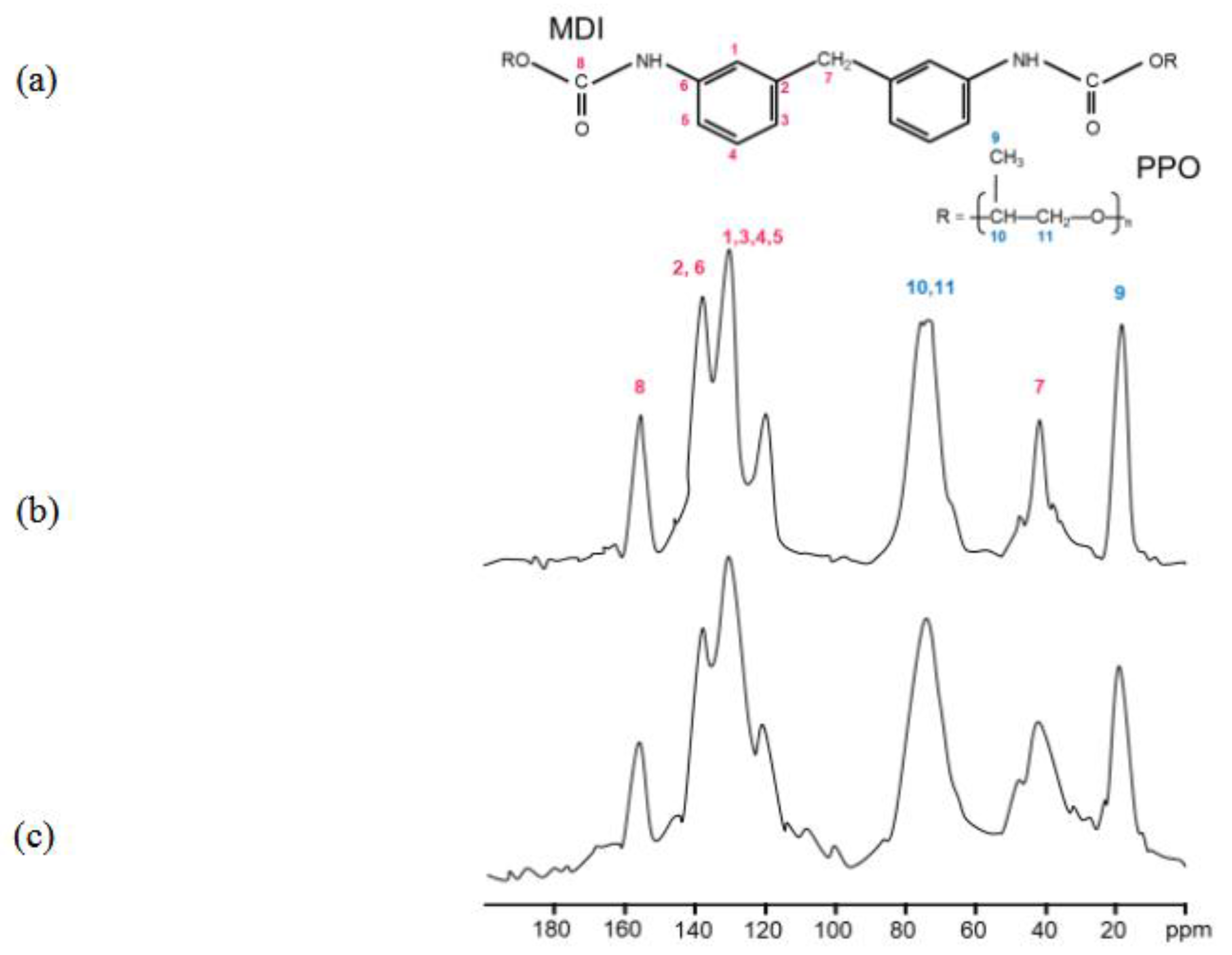
PU foams derived from different types of industrial PU waste sources (e.g. automotive or packing materials) showed oil sorption capacities ranging from 10 g/g and 20 g/g (
Figure 3a). In particular, it was observed that some samples, such as the steering wheel, exhibited very low efficiency, while the foams obtained by mixing soft PU components (pink line) demonstrated more effective sorption properties, reaching an oil sorption capacity of 30g/g within 1 hour.. These values are in accordance with literature, in which is reported an efficiency for untreated PU foams towards oils in the range of 20-40 g/g (see Table S2) [
22,
23,
24,
28]. The differences are attributed to the specific 3D hierarchical porous structure of the PU foam, which allows water and organic solvents to flow easily into the material, promoting liquid penetration via capillary action
Figures 3b shows the oil sorption capacity of the BMG-PU powders with two different particle sizes ranging from 1 mm to 250 μm and 250 μm to 5μm. Regardless of the primary source, BMG-PU particles with smaller size (250 - 5µm) showed significantly lower oil sorption capacities compared to the corresponding PU foams with values ranging between 3 g/g to 8 g/g. Notably, the soft mixed PU showed a decrease in its oil sorption capacity from 30 g/g to 6 g/g after milling (see
Figure 3b, and Figure S3). Improved performance was observed for the BMG-PU powder fraction with the larger particles (1mm - 250 µm) where the oil sorption capacity ranged from 8 g/g to 20 g/g. Specifically, for the soft mix PU, the oil sorption decreased from 30 g/g in foam to 20 g/g in the powder. Although reduced, this still represents a good result for a PU-based sorbent material. Nevertheless, these findings clearly indicate that the blade milling procedure have a detrimental effect on the intrinsic oil sorption properties of the PU foams. This is likely ascribable to the rupture of their original 3D open-cell structure which is crucial for efficient oil uptake. At the same time, the variation in oil sorption performance among different BMG-PU powder size fractions can be reasonable due to structural and morphological changes induced by the milling process. It is worth to noting here, that the management of the end of life for both PU foams and PU powder is essentially based on controlled incineration treatment with energy recovery. This allows to dispose of oil-PU powder or PU foams under regulated environmental controls and with a positive energy gain, which is higher than that of neat PU. Another alternative strategy is the oil recovery by mechanical squeezing. In this case the absorbed oil can be partially removed. However, differently from PU foams this route has limited applicability to PU powder since it loses its mechanical integrity and foam structure and consequent sorption reversibility and purity, typical of the foams, needed for effective oil removal.
Hereafter, to better elucidate the correlation between the observed changes in oil sorption capacity and the milling treatment, a comprehensive characterization of both the PU foams and resulting BMG-PU powders has been carried out, as presented in the following sections.
3.3. Analysis of Structural, Chemico-Physical Changes Induced by Mechanical Treatment
Solid-state 13C NMR analysis of recycled PU foams
PU foams originating from the dismantling of refrigerators and vehicle components were analysed by
13C solid-state NMR spectroscopy in order to identify the chemical structure of each specific PU foam composition. It is worth mentioning here that PU foams are prepared by the polymerization reaction between a polyol and a polyisocyanate, forming urethane bonds. This process typically requires a catalyst or UV radiation. The resulting foams, either open-cell or closed-cell, are usually produced with one or more blowing agents added during the polymerization step [
6]. Open-cell foams are characterized by ruptured lamellae between adjacent cells, resulting in interconnected porosity. In contrast, closed-cell foams retain intact lamellae, forming isolated gas-filled cells. PU foams are typically formed from randomly segmented copolymers consisting of soft segments and more rigid, urethane-rich hard segments. Their unusual elastomeric properties of arise from the thermodynamic incompatibility between the soft and hard segments of the copolymer, leading to microphase separation, which in turn is governed by thermodynamic factors and the ability of the hard segments to pack efficiently and form hydrogen bonds [
32,
33]. The degree of phase separation is also affected by the chemical structure of PU chains, type of polyols, polarity of the structural fragments, size and molecular weight of hard and soft segments [
34,
35].
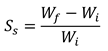
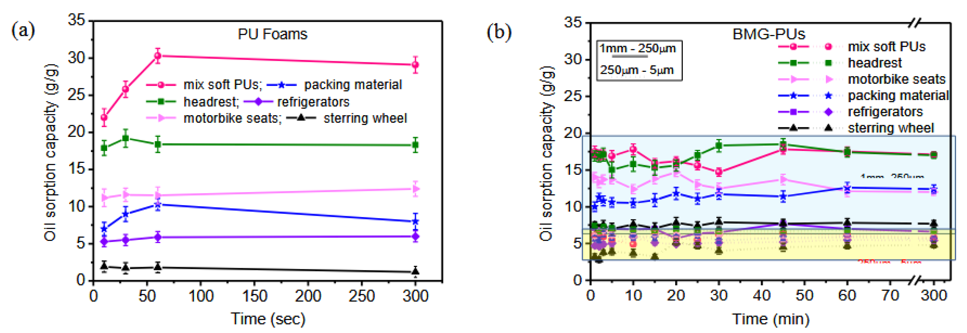
Figure 4 shows the spectra of PU foams with the typical peaks assigned to polyols, including polypropylene oxide (PO) (–CH
3; CH(CH
3)–O; CH
2–O– 12, 73 and 75 ppm, respectively), and aromatic isocyanates, methylene diphenyl diisocyanate (MDI) and 2,4 tolylene diisocyanate (TDI) (CH
3–Ar 18, C arom. 121 and 126, aromatic ring - CH
3136 ppm), as well as the urethane bond (–NH–Ar, –CO–NH–130 and 155 ppm) [
36]. In particular, mixed soft PUs foams (
Figure 4a) and those originating from the recycle of packaging materials, motorbike seats and car headrest (
Figure 4d-f respectively) exhibited peaks associated to MDI, PO, and PO end-functionalized with hydroxyl groups ethylene oxide (EO) (PO-based polyether polyols, PEO). On the other hand insulating panels used in refrigerators exhibited peaks associated to TDI, and PO- PEO (
Figure 4b,c), whereas PU foam of steering wheel showed a more complex structure made of a mixture of MDI and a modified isocyanate, polyether polyols made of low molecular weight PO- PEO, and additives. It is worth noting that rigid PUs are typically made from low molecular weight polyols (a few hundreds), whereas soft PUs are composed of high molecular weight polyols [
28].
13C solid-state NMR of mixed soft PU foams with higher absorption capacity (see the pink curve in
Figure 3a) was also compared with that of the corresponding mixed softBMG-PU powder; i.e the PU ground powder with intermediate size fraction (1mm - 250µm); in order to evaluate potential modification of chemical structure upon mechanical activation. This powder is light brown; had a bulk density of 0.16 g cm
-3; an average content of water of 4% w/w and exhibited a melting temperature of 220°C. The amount of ash produced at 600°C is 27% w/w (see Table S3)
By comparing the NMR spectra, we did not observe any change in the chemical shift positions but a slight broadening of the signals. This suggested that the grinding process introduces structural disorder, enhances surface effects, and eventually reduces chain mobility near the fracture sites, whereas the chemical structure remains largely preserved. Indeed, as reported in literature, a decreased mobility leads to enhanced dipolar interactions and shortened transverse relaxation times, resulting in broader NMR lines.
Figure 5.
(a) Chemical structure and related 13C solid-state NMR signals of MDI and PPO. (b) 13C solid-state NMR spectra of mixed soft PU foams and (c) the corresponding mixed soft BMG-PU with intermediate size fraction (1mm - 250µm).
Figure 5.
(a) Chemical structure and related 13C solid-state NMR signals of MDI and PPO. (b) 13C solid-state NMR spectra of mixed soft PU foams and (c) the corresponding mixed soft BMG-PU with intermediate size fraction (1mm - 250µm).
3.4. Morphological, Structural and Chemico-Physical Changes Induced by the Grinding Process
Hereafter, the morphology, structural and chemico-physical changes induced by the grinding process was investigated focusing on the more absorbing PU foams, i.e., soft mixed PU foams, and the corresponding BMG-PU particles with intermediate size fraction (1mm - 250µm).
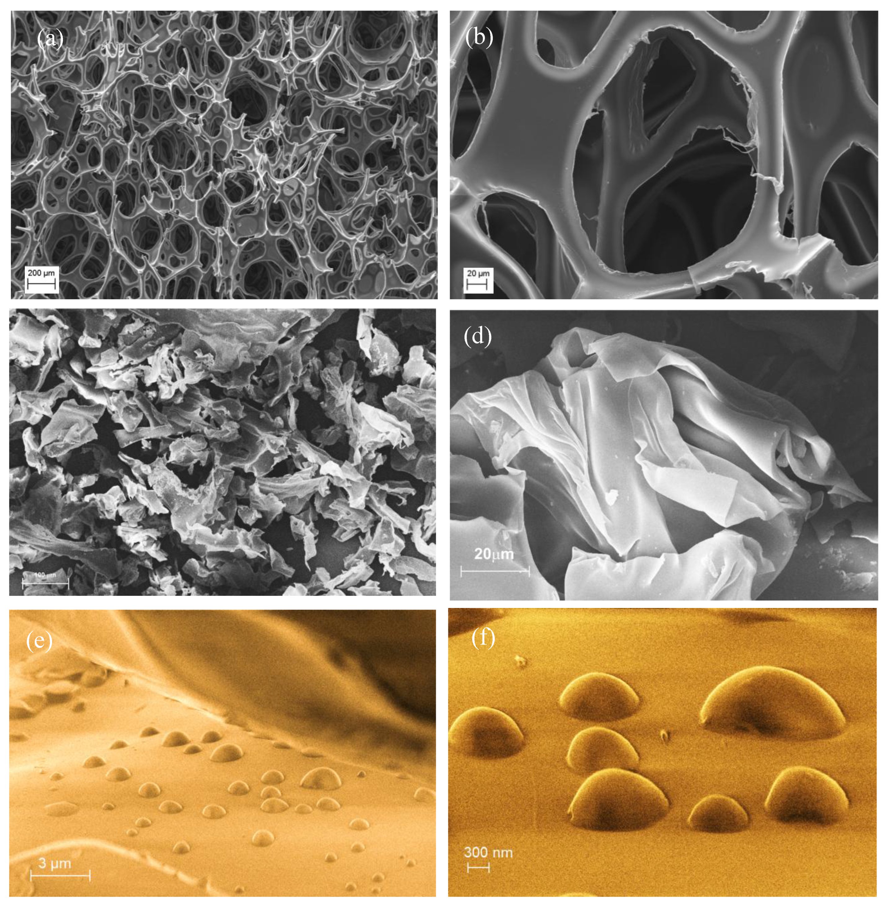
SEM analysis performed on both the samples (
Figure 6) confirmed the collapse and compression of the typical PU foam structure (
Figure 6a, b and Figure S4) with the formation of small particles and fragments of irregular shapes, highlighting a more disordered spatial arrangement, such as multiple folding of the polymer sheets (see
Figure 6c). These structures featured as planar sheets or thin membranes and for the most part shaped into soft flakes similar to that displayed in
Figure 6d.
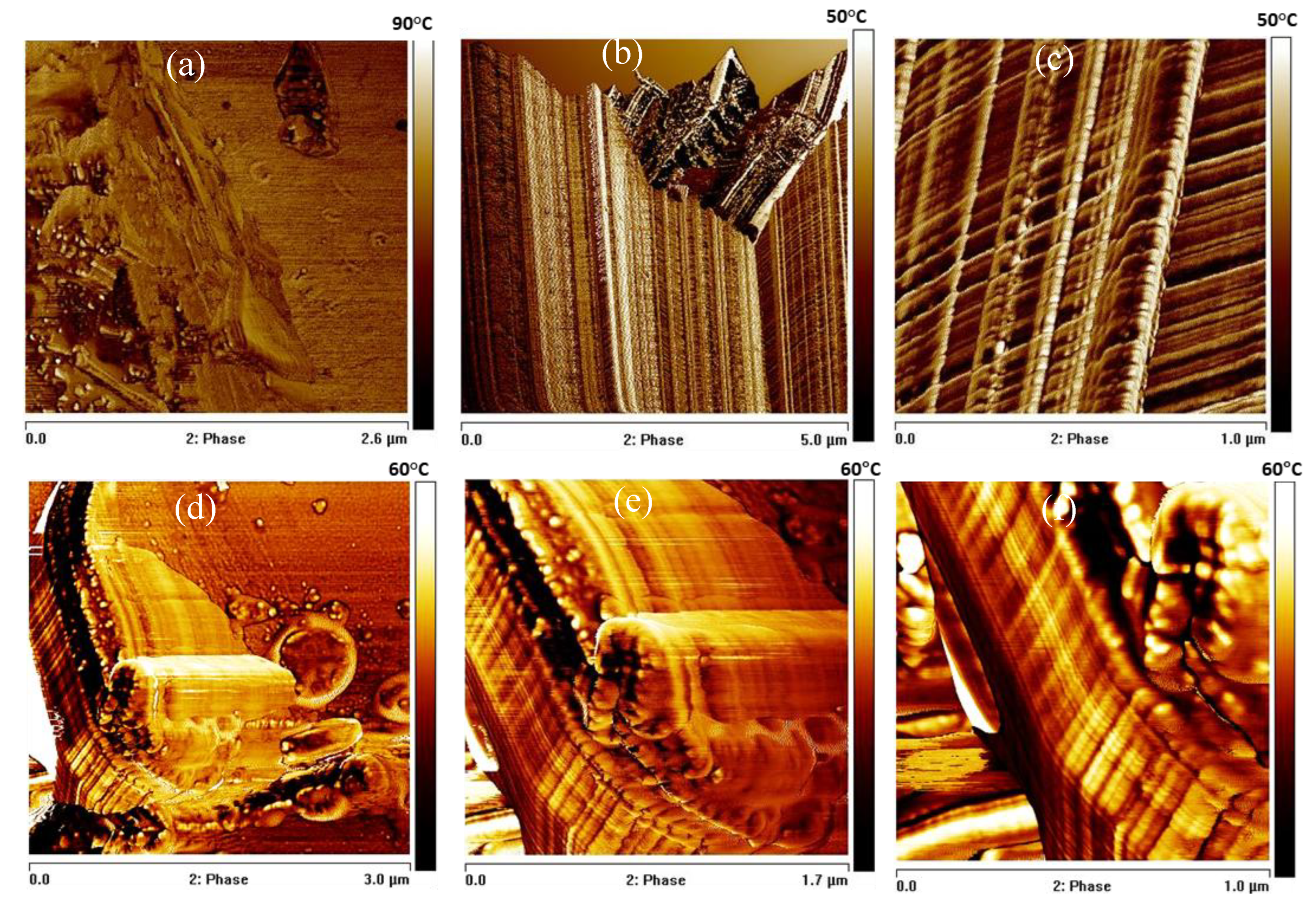
The surface morphology was also investigated by AFM. The pristine soft PU foam surface (
Figure 7a) exhibits the characteristic irregular and heterogeneous topography typical of microcellular PU foams. After blade-milling BMG-PUs showed a highly irregular and rough topography characterized by significant heterogeneity and fractured features (see
Figure 7b, c). In line with the literature, the high contrast in the phase images revealed variations in local stiffness and adhesion arising from the presence soft and hard domains, or urea/urethane crystallites [
37,
38,
39]. In addition, the phase images clearly shows the extensive fragmented portions with well-ordered and aligned structures probably determined by the mechanical action of the blade-milling process. As clearly displayed in
Figure 7c these ordered regions consist of parallel, well-aligned microstructures, perpendicularly interconnected each other by regularly spaced and variably folded segments, composed basically of hard domains within a softer matrix. In addition, in proximity of the cutting areas, localized deformations and rearrangements are observed. As shown in
Figure 7b , blade-milling gave rise to V-shaped discontinuities and fragmentation of the surface. In some regions, the regular array of lamellae was partly preserved, whereas in others appeared almost completely disrupted, producing loose or protruding chain fragments and irregular domains. Small displaced fragments, attributed to chain segments exposed by mechanical scission, appear to undergo partial 3D reorganization at the surface.
Thus, in line with NMR analysis the AFM observations suggest that the mechanical treatment induces considerable physical modification and chemical surface reorganization, without altering the fundamental chemical structure of the PU network.
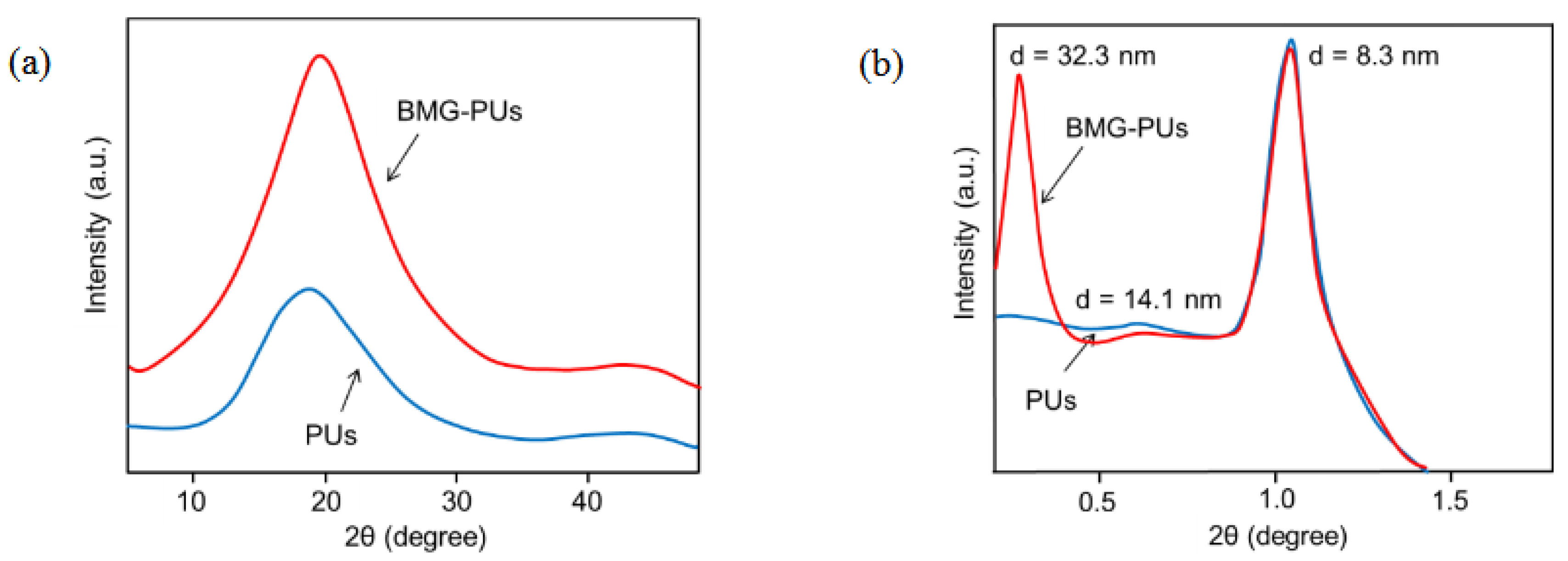
To gain further insights into the structural changes induced by the milling process, mixed soft PU foams and BMG-PU powder were analyzed by X-ray diffraction (XRD) analysis. Wide-angle diffraction (WAXD) patterns of both the samples (
Figure 8a) exhibited a broad peak centered at 19° 2θ, and a smaller broad peak at 44º 2θ, which are due to the characteristic amorphous regions of the PU [
40,
41,
42]. At the same time, the small-angle X-ray scattering (SAXS) analysis exhibited peaks at < 2° 2θ characteristic of the typical long-range order and microphase separation of soft PU [
43,
44]. However, compared to the foams the diffraction pattern of the corresponding powder (
Figure 8b) revealed the appearance of a new scattering peak at very low angle (≈ 0.27° 2θ) probably due to large-scale aggregates of rigid domains originating from the re-organization of hard-segment domains upon mechanical shear and compression. This is in line with literature, where the intense signal close to the beam stop was associated to the formation of well-large, micron-sized aggregates of hard segments that form due to microphase separations [
45].
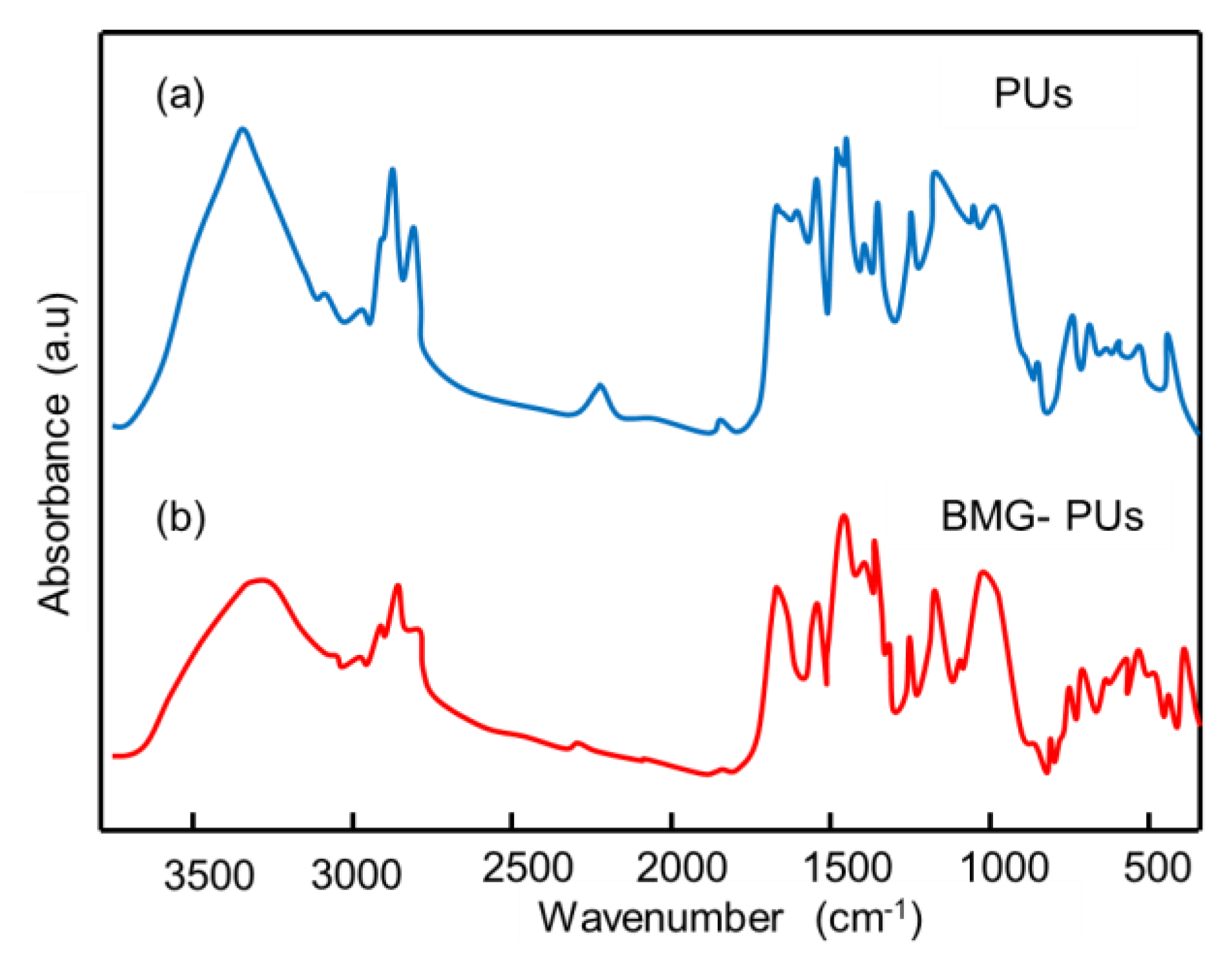
FTIR analysis were performed on mixed soft PU foams and BMG-PUs (
Figure 9 a,b) to investigate structural or functional micro arrangements and the potential formation of new bonds resulting from mechanochemical activation. In line with NMR, the FTIR spectrum of PU foam confirmed the characteristic structure of MDI-PPO-based PU foam [
46]. In contrast, the spectrum of the BMG-PU displayed a different pattern, characterized by an increased intensity in the vibrational bands of the -CH
2 and -CH groups (hydrocarbon chains) in the range of 2972 - 2851 cm
-1, and in the–OH stretching bands at approximately 3335-3450 cm
-1, suggesting a higher concentration of hydroxyl groups, either free or associated with polyols. Notably, changes in the C=O band associated with urethane linkages (~1725 cm⁻¹), along with the disappearance of the –NCO stretching band at 2278 cm
-1, suggest the formation of new urethane bonds via the reaction of isocyanate groups with hydroxyl groups from polyols [
47]. This was further supported by the increase of the bands at 1538 cm⁻¹ and 1227 cm⁻¹, corresponding to N–H bending (δ(N–H)) and C–N stretching vibrations, respectively, as well as to the increase of the band at 1313 cm⁻¹, attributed to a combination of N–H bending (δ(N–H)), C–N stretching (ν(C–N)) and C–H bending (β(C–H)).
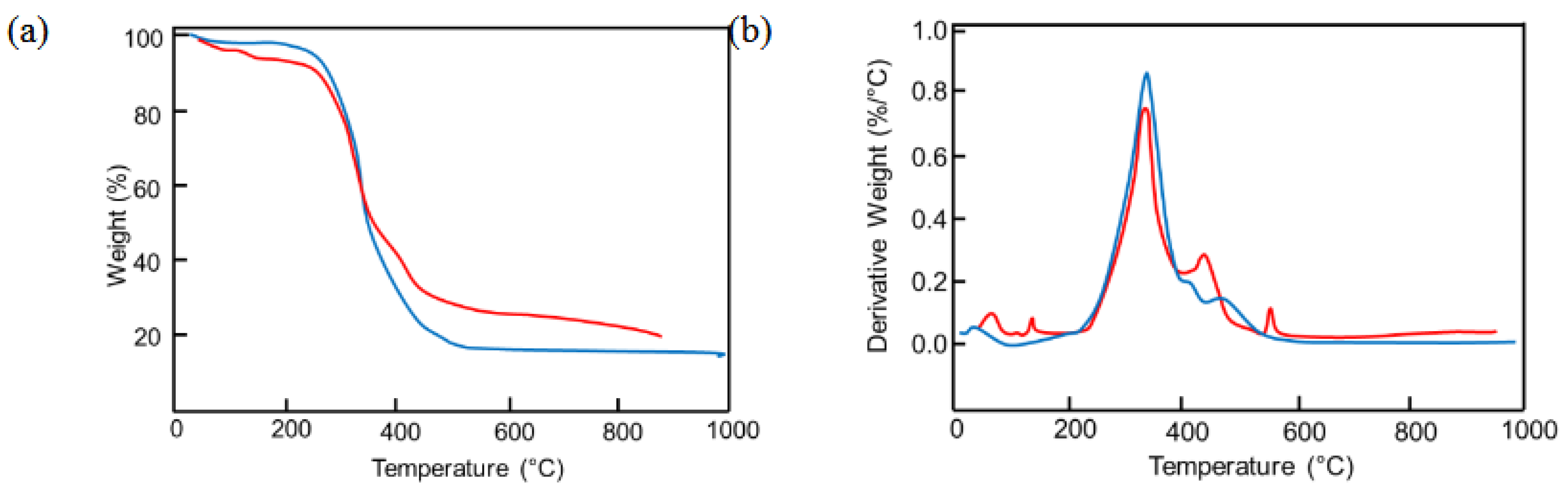
Finally, TGA and DTG (
Figure 10) were performed to compare the thermal behavior of soft PU foams and BMG-PUs and evaluate structural changes induced by grinding. The thermal degradation of PU foams typically occurs between 220°C and 600° with three distinct weight loss steps corresponding to the progressive breakdown of different polymer segments and breakage of various chemical bonds (
Figure 10a). Weight losses observed below 220°C are typically attributed to the desorption of water molecules adsorbed onto the polymer surface. Based on the literature [
48,
49,
50], the main thermal degradation step, occurring between 300°C and 350°C, is attributed to the decomposition of urethane bonds, while the subsequent two steps, occurring at approximately 400°C and 480°C, are due to the decomposition of ether and ester bonds, respectively. In our case, the first degradation step was responsible of ca. 70% of the total weight loss, while the other two steps contributed about 28%. Compared with PU foams the DTG profile of BMG-PU (
Figure 10b) showed an overall similarity with difference in the distribution of weight losses. The degradation associated with the breakage of the urethane bond was around 59% of the total weight loss and the breakdown of ether and ester bonds represented approximately 37%. This suggests that despite the formation of additional urethane linkages, through the reaction of isocyanate with hydroxyl functional groups, there is also a decrease in the urethane/ester ratio, from 2.5 to 1.6, that can be ascribed to the preferential degradation of the polyol component (see Table S4), resulting in shorter but more rigid chain segments. The relative increase of polyols was also supported by the increased weight loss observed around 550°C, as well as by the appearance of minor peaks below 200°C. These low-temperature losses can suggest structural modifications, i.e indicating the presence of different types of hydrogen bonding and van der Waals interactions between water molecules and the BMG-PU.
Structural changes induced by blade-milling were further evidenced by the differences observed in the DTA curves (Figure S5). Along with the two main exothermic process occurring at 300-400 °C and in the temperature range of 450-600 °C. DSC analysis showed a significant difference in the melt temperature (Tm) which was more marked for PU foams than BMG-PU, as clearly evidenced by the sharp endothermic peak at 120–130°C (see Figure S5a,b). This supports the findings on the microstructural composition of the PU foams after grinding which is mostly characterized by separated component of soft polyols components and aggregates of hard domains.
3.5. Oil Sorption Mechanism of PU Foam and BMG-PU Powder
In light of these results, we observed complementary oil sorption mechanisms for PU foams and their BMG-PUs counterparts. It is evident that blade milling of PU foams leads to a significant reduction in oil sorption capacity. This decrease is proportional to the extent of grinding, with the finest particle fraction (250 μm – 5 μm) showing the lowest sorption capacity.
For pristine mixed soft PU foams, the high oil sorption capacity (20-30 g/g) is associated with their structural and surface features, characterized by 3D open-cell, high surface area and well interconnected pores, which facilitate capillary-driven oil uptake. As a consequence, the decrease after mechanical treatment is basically due to the rupture of this 3D porous cell structure and the concurrent reduction in surface area. In contrast, the mechanical treatment has a negligible effect on the oil sorption capacity of rigid PU foams, which show similar values (about 5 g/g) before and after grinding. This behavior is in line with the literature and is attributed to their closed-cell structure, lower porosity and higher density, all of which hinder oil penetration and limit the internal volume available for oil uptake.
In the case of soft BMG-PUs, with variable oil sorption capacity, the key factors influencing oil uptake are related to surface chemical characteristics and their structural features, particularly involving the distribution and length of hard and soft segmented domains. As clearly highlighted by FTIR and thermal analysis blade milling induces an increase in the amount of the polyol (PPO) component, and consequently, a higher concentration of free hydroxyl groups. Simultaneously, hard (urethane) segments undergo fragmentations in shorter structures and tend to aggregate in larger rigid domains (structural and AFM analysis). It also noteworthy that the energy required for ductile rupture in PU foams exceeds the intrinsic bond fracture energy. This discrepancy is due to additional energy dissipating mechanisms such as plastic deformation occurring during fracture. Therefore, grinding causes multiscale morphological and chemico-phisical surface changes, including rupture of the foam cells and plastic deformation at the mascroscale . as well as modification on the degree of phase separation with a microstructural rearrangement of segmented rigid domains at the microscale. In this regard, AFM phase images of BMG-PU (see
Figure 7b,c) clearly showed the alignment of hard segments parallel to the direction of mechanical stress, along with the formation of perpendicular, interlocking hard domain structures. These considerations are in line with SAXS which reveals the formation of large aggregates resulting from packing of hard domains within the soft matrix. Taking into account these considerations, we speculated that upon mechanical pulverization the PU foams dissociate into smaller, and regular fragments, where hard segments tend to aggregate into larger structures within the soft matrix.This results in aggregated hard segments with greater separation, contributing to altered oil sorption behavior.
As a result, the disruption of PU foams and the associated microstructural rearrangement of segmented domains, characterized by shortened hard segments, reduced hydrophilic urethane content, and increased polyol concentration, play a role on the oil sorption capacity of the different BMG-PU powder, especially for those with intermediate dimensions (1mm - 250μm). The chemico-physical surface and morphological reorganization resulted in densely packed oleophilic domains, which in turn influences the oil uptake, as shown in AFM phase images (
Figure 7d-f) and SEM micrographs, where oil droplets are visibly adhered to the surface and fill oleophilic regions through a coalescence mechanism, similar to a “sandwich effect“ (
Figure 6e,f and S6).
4. Conclusion
In this work, we studied the oil sorption capacity of recycled PU foam wastes, both rigid and soft and the corresponding BMG-PU powders obtained by blade milling treatment. The effect on the oil sorption of BMG-PUs was also investigated with respect to the morphological, microstructural and chemical modifications induced by mechanical action. The grinding process gave rise to two particle fractions of BMG-PUs with different sizes, ranging from 1 mm to 250 μm and 250 μm to 5 μm, as clearly highlighted by laser diffraction and optical microscopy. The oil sorption measurements revealed that pristine soft PU foams and the corresponding BMG-PUs with intermediate particle size (1 mm –250 μm) exhibited the highest oil uptake (30 -20 g/g), whereas the finest fraction (250 μm – 5 μm) showed lower capacity (3-7 g/g). In contrast, rigid PU foams showed the lowest oil sorption values (~5 g/g) with negligible differences between the foams and the BMG-PU powder. By the evaluation of the structural and morphological changes induced by the grinding process, the decrease of oil sorption after mechanical treatment, especially for smaller particle fraction, is attributed to the rupture of the typically 3D porous structure and interconnected cells of PU foams, which are responsible for effective oil uptake by acting as a “cage” for the oil. The collapse of these structure and the morphology features were evidenced by SEM and AFM characterizations. The evaluation of the structural and chemico-physical changes induced by blade milling was performed on the most absorbent PU foam, i.e mixed soft PUs, before and after grinding, by combining X-Ray diffraction with spectroscopic FTIR analysis and the study of thermal behavior (TGA/DTG, DTA). Interestingly, we found that the mechanical treatment determined a rearrangement at the micro scale of the segmented domains of the polymer chains characterized by shortened and aggregated hard segments, reduced hydrophilic urethane content, and increased polyol concentration. These modifications enables the formation of more densely packed oleophilic domains, affecting the oil uptake, where oil droplets adhere to the surface and fill oleophilic regions. Therefore, in a different way from the pristine PU foams, the BMG-PU powder presents a different sorption mechanism where the resulting fragments of the disrupted foam structure, characterized by a different segmented domains arrangement with aggregates of hard domains within the soft phase capture small oil droplets through a coalescence mechanism similar to a “sandwich effect“. The subsequent aggregation oil/powder leads to an increase in total volume and stabilization of oil within the polymer sorbent.
Although the reduced performance compared to pristine PU foams, the absorbing BMG-PU powders, especially those with intermediate dimensions and originating from soft PU foams, can represent an alternative solution for oil sorption and eventually of oil spill cleanup, making at the same time more sustainable, versatile, and less expensive the management of PU foam waste materials
Acknowledgments
The authors posthumously thank Dr. Donatella Capitani for her invaluable advice in performing NMR and support for NMR analysis. We thank Mr. Fulvio Federici and Mrs. Emanuela Tempesta for their technical assistance. We thank Dr. Matteo Paciucci for performing SEM analysis on the pristine soft PU foam. We also thank Dr. Paolo Ciccioli for his critical discussion in the early stages of this research. This research work was entirely supported by National Research Council (CNR) own funds, and partially by the project “Progetto Sviluppo delle Infrastrutture e Programma Biennale degli Interventi” – Delibera 136/2020 CUP B55J19000360001- Progetto n.52 Laboratorio Surface.
References
- Akindoyo J.O.; Beg M.D.H.; Ghazali S.; Islam M.R.; Jeyaratnam N.; Yuvaraj A.R.; Polyurethane types, synthesis and applications – a review. RSC Adv 2016, 6, 114453–82. [CrossRef]
- Krol P. Synthesis methods, chemical structures and phase structures of linear polyurethanes. Properties and applications of linear polyurethanes in polyurethane elastomers, copolymers and ionomers. Prog Mater Sci 2007, 52, 915–1015. [CrossRef]
- Laurichesse S.; Avérous L.; Chemical modification of lignins: Towards biobased polymers Prog. Polym. Sci., 2014, 39, 1266–1290. [CrossRef]
- Ates M.; Karadag S.; Ekerc A.A.; Ekerd B.; Polyurethane foam materials and their industrial applications Polym Int 2022; 71: 1157–1163. [CrossRef]
- Szycher M.; Szycher’s Handbook of Polyurethanes, CRC Press, Boca Raton, 2nd edn, 2017.
- Wu S.; Ma S.: Zhang Q.; Yang C. A comprehensive review of polyurethane: Properties, applications and future perspectives Polymer 2025, 327, 16, 128361. [CrossRef]
- Chaudhary M. L.; Gupta R. K. Polyurethanes: An Introduction in Non-Isocyanate Polyurethanes: Chemistry, Progress, and Challenges. ACS Symposium Series 2025 Vol. 1507, 1-14. doi/10.1021/bk-2025-1507.ch001.
- Chaudhary M. L.; Patel R.; Gupta R. K. Beyond isocyanates: Advances in non-isocyanate polyurethane chemistry and applications. Polymer, 2025, 332, 128553. [CrossRef]
- Maamoun A. A.; Arafa M.; Esawi A.M. K. Flexible polyurethane foam: materials, synthesis, recycling, and applications in energy harvesting – a review. Mater. Adv., 2025, 6, 1842-1858. [CrossRef]
- Qiu J.; Zhao H.; Luan S.; Wang L.; Shi H. Recent advances in functional polyurethane elastomers: from structural design to biomedical applications. Biomater. Sci., 2025, 13, 2526-2540. [CrossRef]
- Jayalath P.; Ananthakrishnan K.; Jeong S.; Shibu R. P.; Zhang M.; Kumar D.; Yoo C. G.; Shamshina J. L.; Therasme O. Bio-Based Polyurethane Materials: Technical, Environmental, and Economic Insights. Processes., 2025, 13(5), 1591; [CrossRef]
- Rossignolo G.; Malucelli G.; Lorenzetti A.; Recycling of polyurethanes: where we are and where we are going. Green Chem., 2024, 26, 1132 . [CrossRef]
- Yang W.; Dong Q.; Liu S.; Xie H.; Liu L. and Li J.; Recycling and Disposal Methods for Polyurethane Foam Wastes. Procedia Environ. Sci., 2012, 16, 167–175. [CrossRef]
- Datta J.; Głowińska E.; Włoch M.; Mechanical Recycling via Regrinding, Rebonding, Adhesive Pressing, and Molding, in Recycling of Polyurethane Foams, ed. T. Sabu, A. V. Rane, K. Krishnan, V. K. Abitha and G. T. Martin, William Andrew Publishing, 2018, pp. 57–65.
- Nafziger J. L.; Lowenkron S. B.; Koehler C. E.; B. N. Stevens, Flexible polyurethane rebond foam having improved tear resistance and methodfor the preparation thereof, U.S. Patent 5312888, 1994.
- Santucci, V.; Fiore, S. Recovery of Waste Polyurethane from E-Waste—Part I: Investigation of the Oil Sorption Potential. Materials 2021, 14, 6230. [CrossRef]
- Lee H.; Chen G.; Chang B.P.; Mekonnen T.H.; Recent progress in the development of porous polymeric materials for oil ad/absorption application RSC Appl. Polym., 2025, 3,43 . [CrossRef]
- de Folly d'Auris, A.; Rubertelli, F.; Taini, A.; Vocciante, M. A novel polyurethane-based sorbent material for oil spills management, J. Environ Chem Eng, 2023, 11 (6), 111386. [CrossRef]
- Dacewicz E.; Grzybowska-Pietras J.; Polyurethane Foams for Domestic Sewage Treatment. Materials, 2021, 14 (4)933 . [CrossRef]
- Wang J.; Chen Y.; Xu Q.; Cai M.; Shi Q.; Gao J.; Highly efficient reusable superhydrophobic sponge prepared by a facile, simple and cost effective biomimetic bonding method for oil absorption. Scientific Reports 2021 11, 11960. [CrossRef]
- Al-Khalaf A.A.; S. Al-Lami H.; Abbas A.F.: Flexible polyurethane foam with improved oleophilic and hydrophobic properties for oil spill cleaning, Petroleum Sci Technol, 2022 42(3), 287–302. [CrossRef]
- Liu H.-D.; Wang Y.; Yang M.-B.; He Q.; Evaluation of Hydrophobic Polyurethane Foam as Sorbent Material for Oil Spill Recovery, J. Macromol Sci Part A: Pure and Applied Chemistry, 2014, 51:1, 88-100. [CrossRef]
- Tomon T.R.B.; Omisol C.J.M.; Aguinid B.J.M.; Sabulbero K.X.L. ; Alguno A.C.; Malaluan R.M.; Lubguban A.A.; A novel naturally superoleophilic coconut oil-based foam with inherent hydrophobic properties for oil and grease sorption Scientific Reports 2024 14:14223. [CrossRef]
- Ma X.; Zhang C.; Gnanasekar P.; Xiao P.; Luo Q. ; Li S.; Qin D. ; Chen TChen .; J.; Zhu J.; Yan N.; Mechanically robust, solar-driven, and degradable lignin-based polyurethane adsorbent for efficient crude oil spill remediation. Chem Eng Journal 2021 415, 128956. [CrossRef]
- Li X.; Zhang J.; Liu H.; Li Z.; Zheng G.; Zhou L.; Fu P.; Sustainable superhydrophobic lignin-based polyurethane foam: an innovative solution for oil pollutant adsorption. RSC Adv., 2025, 15, 377-387 . [CrossRef]
- Calcagnile P.; Fragouli D.; Bayer I.S.; Anyfantis G.C.; Martiradonna L.; Cozzoli P.D.; Cingolani R.; Athanassiou A.; Magnetically driven floating foams for the removal of oil contaminants from water, ACS Nano 2012, 6 (6) () 5413–5419. [CrossRef]
- Li H.; Liu L.; Yang F.; Oleophilic polyurethane foams for oil spill cleanup Procedia Environmental Sciences 2013, 18, 528 – 533 . [CrossRef]
- Ng, Z.C.; Roslan, R.A.; Lau, W.J.; Gürsoy, M.; Karaman, M.; Jullok, N.; Ismail, A.F. A Green Approach to Modify Surface Properties of Polyurethane Foam for Enhanced Oil Absorption. Polymers 2020, 12, 1883. [CrossRef]
- Olivito, F.; Ilham, Z.; Wan-Mohtar, W. A.; Oza, A. I.; Procopio, G., A.; Nardi, M. Oil Spill Recovery of Petroleum-Derived Fuels Using a Bio-Based Flexible Polyurethane Foam. Polymers 2025, 17(14), 1959; [CrossRef]
- Xiong S., Zhang K., Wang C., Wang G., Wang X., Xia L., Xia G., Hua C. The Influence of Enclosed Isocyanate Dosage on the Reaction Rate, Mechanical Properties and Grinding Performance of Polyurethane Grinding Wheels J Appl. Polym Sci 2025 142, 22 pp . [CrossRef]
- K. Szadkowska, N. Kępczak, W. Stachurski, Pawłowski W., Rosik R., Bechciński G., Sikora M., Witkowski B.Sikorski J. Influence of Machining Parameters on the Surface Roughness and Tool Wear During Slot Milling of a Polyurethane Block. Materials 2025, 18(1), 193; [CrossRef]
- Velankar, S.; Cooper, S.L. Microphase separation and rheological properties of polyurethane melts. 3. Effect of block length. Macromolecules 1998, 31, 9181–9192. [CrossRef]
- Yilgör, I.; Yilgör, E.; Wilkes, G.L. Critical parameters in designing segmented polyurethanes and their effect on morphology and properties: A comprehensive review. Polymer 2015, 58, A1–A36. [CrossRef]
- Paez-Amieva, Y.; Martín-Martínez, J.M. Understanding the Interactions between Soft Segments in Polyurethanes: Structural Synergies in Blends of Polyester and Polycarbonate Diol Polyols. Polymers 2023, 15, 4494. [CrossRef]
- Fernandes, I.d.A.A., de Oliveira, A.P.P., Bassetti, F.d.J., Kloss, J.R. and Coral, L.A.d.A. Bio-based polyurethanes: a comprehensive review on advances in synthesis and functionalization. Polym Int. 2025, 74, 11, 941-957 . [CrossRef]
- Suganuma, K., Matsuda, H.; Asakura, T. Characterization of polyurethane and a silk fibroin-polyurethane composite fiber studied with NMR spectroscopies. Polym J 2022 54, 803–813. [CrossRef]
- Cheng, B.X., Gao, W. C.; Ren, X.M.; Ouyang, X. Y.; Zhao, Y.; Zhao, H.; Wu, W.; Huang, C. X.; Liu, Yang.; Liu, X.Y.; Li, H. N.; Li, R.K.Y. A review of microphase separation of polyurethane: Characterization and applications. Polymer Testing. 2022 107, , 107489. [CrossRef]
- Sheth, J.P. et al., Probing the Hard Segment Phase Connectivity and Percolation in Model Segmented Poly(urethane urea) Copolymers. Macromolecules, 2005, 38, 5681-5.
- Peter Schön, et al., Quantitative mapping of elastic moduli at the nanoscale in phase separated polyurethanes by AFM, Eur. Polym. J., 2011, 47, 692-698.
- de Souza F.M.; Kahol P.K.; Gupta R.K.; Introduction to Polyurethane Chemistry. In Gupta and Kahol; Polyurethane Chemistry: Renewable Polyols and Isocyanates In ACS Symposium Series; 2021,1, 1-24. [CrossRef]
- Trovati G.; Sanches E.A.; Neto S.C., Mascarenhas Y.P.; Chierice G.O.;. Characterization of polyurethane resins by FTIR, TGA, and XRD, J Appl Polym Scie; 2010 115, 1 () 263-268. [CrossRef]
- Schemmer B.; Kronenbitter C.; Mecking S.; Thermoplastic Polyurethane Elastomers with Aliphatic Hard Segments Based on Plant-Oil-Derived Long-Chain Diisocyanates. Macromol Mater Eng 2018, 303, 4. – 1700416. [CrossRef]
- Dias R.C.M.; Góes A.M.; Serakides R.; Ayres E.; Oréfice R.L.;. Porous Biodegradable Polyurethane Nanocomposites: Preparation, Characterization, and Biocompatibility Tests. Materials Research. 2010; 13(2): 211-218. [CrossRef]
- Laity, P.R., Taylor, J.E., Wong, S.S., Khunkamchoo, P., Norris, K., Cable, M., Andrews, G. T., Johnson, A.F., Cameron, R.E. A 2-dimensional small-angle X-ray scattering study of the microphase-separated morphology exhibited by thermoplastic polyurethanes and its response to deformation. Polymer 2004 45, 5215–5232. https://doi. 10.1016/j.polymer.2004.05.032].
- Chen, C.P.; Dai. S. A.; Chang, H.L.; Su, W.C.; Wu, T.M.; Jeng, R. J. Polyurethane elastomers through multi-hydrogen-bonded association of dendritic structures. Polymer, 2005, 11849-11857.
- Lee H.T.; Lin L.H.; Waterborne Polyurethane/Clay Nanocomposites: Novel Effects of the Clay and Its Interlayer Ions on the Morphology and Physical and Electrical Properties. Macromolecules 2006; 39(18), 6133-6141. [CrossRef]
- Stanzione, M.; Russo, V.; Oliviero, M.; Verdolotti, L.; Sorrentino, A.; Di Serio, M.; Tesser, R.; Iannace, S.; Lavorgna, M. Synthesis and characterization of sustainable polyurethane foams based on polyhydroxyls with different terminal groups. Polymer 2018, 149, 134-145. [CrossRef]
- Burelo, M., Franco-Urquiza, E.A., Martínez-Franco, E., Moreno-Núñez, B.A., Gómez, C.M., Stringer, T. and Treviño-Quintanilla, C.D. Effect of Thermal Aging on Polyurethane Degradation and the Influence of Unsaturations in the Hard Segment. J Polym Sci, 2025 63: 2639-2650. DOI: 2481/10.1002/pol.20250260.
- Li, X.-B., Cao, H.-B. and Zhang, Y. Thermal degradation kinetics of rigid polyurethane foams blown with water. J. Appl. Polym. Sci., 2006 102: 4149-4156. [CrossRef]
- Liu, S.-H.; Shen, M.-Y.; Kuan, C.-F.; Kuan, H.-C.; Ke, C.-Y.; Chiang, C.-L. Improving Thermal Stability of Polyurethane through the Addition of Hyperbranched Polysiloxane. Polymers 2019, 11, 697. [CrossRef]
Figure 1.
(a) Photographs of pieces of rigid PU foam from recycled insulating panels used in refrigerators, and (b) soft PU foams used for the cushioning of vehicle headrest.
Figure 1.
(a) Photographs of pieces of rigid PU foam from recycled insulating panels used in refrigerators, and (b) soft PU foams used for the cushioning of vehicle headrest.
Figure 2.
(a) Particle size distributions in the volume of BMG-PUs. (b) Typical shapes of BMG-PU particles obtained by blade milling process of the PU foam wastes. Different shapes and dimensions of BMG-PU particles within the ranges of 6-20 μm (top) and 50-250 μm (bottom). The numbers indicate the mean aerodynamic diameter in µm.
Figure 3.
The oil sorption capacity (g/g) of the (a) PU foams, (b) BMG-PU powder with particle size ranging from 1 mm to 250 μm (solid lines), and from 250 μm to 5 μm (short dots line).
Figure 3.
The oil sorption capacity (g/g) of the (a) PU foams, (b) BMG-PU powder with particle size ranging from 1 mm to 250 μm (solid lines), and from 250 μm to 5 μm (short dots line).
Figure 4.
13C solid-state NMR spectra of recycled PU foams: (a) mixed soft PUs, (b) insulating panels for refrigerators, (c) packing materials, (d) motorbike car seats, (e) steering wheel, (f) car headrest.
Figure 4.
13C solid-state NMR spectra of recycled PU foams: (a) mixed soft PUs, (b) insulating panels for refrigerators, (c) packing materials, (d) motorbike car seats, (e) steering wheel, (f) car headrest.
Figure 6.
(a,b) SEM images of mixed soft PU foams before blade milling at different magnifications. (c) Images of fragmented cell structure of mixed soft BMG-PU powder with intermediate size fraction (1mm - 250µm), and (d) a magnification of the typical flake structure of PU fragment generated by mechanical treatment. (e,f) Different magnifications of oil droplets on the surface of BMG-PU powder after oil uptake.
Figure 7.
(a) AFM phase images of mixed soft PU foams, and the (b,c) BMG-PU highlighting the ordered microstructures recorded in the stretched and at the cut edge of the fragmented PU material. (d-f) High magnification phase images of oil sorbed on the polymer surface and within the stretched PU microstructures of BMG-PU.
Figure 8.
(a) WAXD, and (b) SAXS profiles for mixed soft PU foams and BMG-PU powder.
Figure 8.
(a) WAXD, and (b) SAXS profiles for mixed soft PU foams and BMG-PU powder.
Figure 9.
Comparison of FTIR spectra of (a) mixed soft PU foams, and (b) the corresponding BMG-PUs.
Figure 9.
Comparison of FTIR spectra of (a) mixed soft PU foams, and (b) the corresponding BMG-PUs.
Figure 10.
(a) TGA and (b) DTG of mixed soft PU foams (blue curves) and BMG-PUs (red curves).
Figure 10.
(a) TGA and (b) DTG of mixed soft PU foams (blue curves) and BMG-PUs (red curves).
|
Disclaimer/Publisher’s Note: The statements, opinions and data contained in all publications are solely those of the individual author(s) and contributor(s) and not of MDPI and/or the editor(s). MDPI and/or the editor(s) disclaim responsibility for any injury to people or property resulting from any ideas, methods, instructions or products referred to in the content. |
© 2025 by the authors. Licensee MDPI, Basel, Switzerland. This article is an open access article distributed under the terms and conditions of the Creative Commons Attribution (CC BY) license (http://creativecommons.org/licenses/by/4.0/).