
Submitted:
09 December 2025
Posted:
10 December 2025
You are already at the latest version
Abstract
Nowadays, decarbonization of the shipping industry has become the top priority of the maritime community. In an effort to reduce emissions from shipping, numerous tech-nological and design solutions are being investigated; Waste Heat Recovery (WHR) by marine engines is one of the most important and widespread ones. This paper investi-gates the utilization of a carbon dioxide Supercritical Brayton Cycle (SBC) for WHR of a LNG carrier. SBC is an innovative, promising technology for power generation with unprecedented performance and a small form factor, due to the properties of the working fluid. A thermodynamic model is developed and programmed in MATLAB using the CoolProp free library. By means of this model, the performance of simple and recuperated SBC (RSBC) for WHR of a specific marine engine at its full load operation is assessed and the optimum compressor pressure ratio for power maximization of the RSBC is selected. The combined system Diesel-RSBC exhibits an increase of about 2.9% in thermal efficiency and a similar reduction in specific fuel oil consumption, com-pared to the sole power production by the Diesel engine, at its full load operation. Sig-nificant performance benefits are also demonstrated at part-load operation of the main engine. To assess how the benefits scale with the main engine power, seven similar marine engines of different power are considered, revealing a possible relationship between the optimal pressure ratio and SBC efficiency with the engine’s exhaust gas temperature.
Keywords:
supercritical CO2 cycle
; waste heat recovery
; recuperator
; combined cycle
; LNG carrier
1. Introduction
Climate change has been the center of attention during the 21st century and decarbonization of the industry seems to be mandatory. Maritime transportation plays an important role in the worldwide economy and despite being one of the most efficient means of transportation, it still has a significant and continuously growing share in worldwide emissions. With shipping being responsible for around 2.9% of global emissions caused by human activities, and these emissions being suspected to grow anywhere from 90% to 130% of 2008 emissions by 2050 [1], it is mandatory for immediate action to be taken in order to reduce them. In 2018, the International Maritime Organization (IMO) announced a new policy framework with the ambition of cutting down greenhouse gases (GHG) emissions at least in half by 2050 compared to their level in 2008, with the ultimate goal to phase out GHG emissions from shipping as soon as possible. Moreover, this policy framework aims to reduce the carbon intensity of international shipping by at least 40% by 2030, with efforts to reduce it by 70% by 2050 compared to 2008 [2].
With shipping being a multi-trillion dollar industry, projected to grow even more in the upcoming years, it is clear that its decarbonization will be a huge economic and logistic challenge. The presently available technology is simply not capable of achieving IMO’s goals for decarbonization [3], thus the improvement of existing and the development of new ways of improving energy efficiency of ships are urgently needed. Even though there is a wide variety of potential design and operational solutions to improve a vessel’s energy efficiency, modifying the propulsion and power systems seem to be the most direct and promising ones. Modern ships mainly rely on diesel engines for both propulsion and electric power generation, so naturally, changing the fuel used in shipping seems to be the best solution for achieving IMO’s long term goals for decarbonization. Fuels like ammonia could in theory be used to achieve zero CO2 emissions, however, each one of these fuels poses new technical challenges that make their implementation difficult. For example, ammonia is a very toxic and difficult to store substance, not to mention its very limited availability and high cost [4]. Furthermore, careful life cycle assessment of any proposed fuel is required in order to correctly assess the overall CO2 emissions taking into account not only those from its combustion but also possible indirect ones during its production or supply chain. These challenges, although not insurmountable, make the successful implementation of a new fuel uncertain. Thus, no potential candidate for improving the ship’s energy efficiency shall be ruled out, as it could end up helping with the decarbonization of the industry in the mid or long term.
The use of turbines (e.g. steam or gas turbines) has not succeeded to dominate the shipping industry. Steam turbines, despite being the main mean of propulsion in the early days of steam ships, have quickly become obsolete due to the use of diesel engines. Another prime example of this phenomenon is Liquifed Natural Gas (LNG) carriers, a relatively modern ship type, initially using steam turbines as their main propulsion system, in order to take advantage of the boil off gas. Yet again, dual fuel marine diesel engines have quickly replaced those systems, proving once again that diesel engines are more suitable for the propulsion and power generation onboard a ship. There are in fact many reasons why diesel engines are the main mean of ship propulsion today, the most important ones being efficiency, weight and space. The factors of weight and space are pretty self-explanatory. The more spacious and heavy a propulsion system is, the less amount of cargo can be carried by a ship of given displacement. In terms of efficiency, modern day diesel engines are more efficient in partial loads than steam and gas turbines, thus making them a more attractive solution for ship owners [5].
The carbon dioxide Supercritical Brayton Cycle (SBC), is a state-of-the-art technology utilizing the properties of CO2 in its supercritical state, in order to increase the thermal efficiency of the conventional Brayton cycle. The use of supercritical CO2 as the working fluid allows for a very compact installation due to its properties. The SBC has been proven to be a very promising solution to increase the energy efficiency of onshore power plants, where steam and gas turbines are still the dominant means of power generation. Despite the promise it has shown in this scenario, rather little research has been done so far in terms of its potential use on ships. Since the SBC seems highly unlikely to be used as the main method of propulsion onboard ships in the foreseeable future, the present study focuses on the potential of the SBC as a waste heat recovery system.
In 2016, Kim et al [6] compared nine different SBC layouts for use as a bottoming cycle for a gas turbine. The comparison revealed that the recompression cycle, despite having the highest theoretical thermal efficiency, is not suitable for bottoming cycle applications. Moreover, it was found that a dual heated Brayton cycle with flow split produces the highest net thermodynamic work; this configuration, however, is extremely complex and requires sophisticated operational strategies. In Held et al. [7], a model of a SBC for use in a gas turbine combined cycle power plant was presented and various aspects of the technology were analyzed. The selected configuration was the recuperated Brayton cycle, since more complex architectures like the recompression cycle perform poorly in bottoming cycle applications. Upon further reviewing the relevant literature, it can be concluded that recompression seems not a popular option for waste heat recovery applications. Recuperation on the other hand is very popular among the various configurations, with more than one recuperators being used in some cases. Furthermore, the simplicity, smaller size, and allegedly better off-design performance of the recuperated cycle are great advantages when used for WHR purposes. Due to the aforementioned reasons, the Recuperated Supercritical Brayton Cycle (RSBC) is selected to be the configuration of study for the present work.
In higher pressures, the behavior of real gases deviates from that of ideal gases, since their molecules in practice interact each other. Since most power cycles run on high pressure, it is important to be able to describe the behavior of real gases. Throughout the years, numerous real gas models have been developed. These models express a relation between the three main thermodynamic properties of a gas, namely pressure, volume and temperature. The key difference is that real gas models take into consideration compressibility effects, differences in specific heat capacity, van der Waals forces, non-equilibrium thermodynamic effects etc. Although such analytical models are not always used for most applications, they are necessary at very high pressures near the critical point or near the condensation point [8]. Thus, they are a particularly important tool for analyzing the behavior of SBC. Some of the most commonly used models are the Van der Waals model, Redlich-Kwong model, Berthelot and modified Berthelot model, Dieterici model, Clausius model, Virial model, Peng-Robinson model, Wohl model etc [8]. Alternatively, one can rely upon thermodynamic look-up tables to acquire real gas properties. Such tables are generated using complex models like the ones mentioned above and provide the various thermodynamic properties of a fluid at a given state described by two fluid properties [9]. They are available in the form of databases for a wide variety of fluids and are quite easy to use. Such tables are used herein, by means of utilizing the free CoolProp library [10].
The present work investigates the utilization of a supercritical carbon dioxide Brayton cycle for waste heat recovery from a marine diesel engine powering a LNG carrier. The mindset behind this choice is that the SBC is not yet a mature, widely available technology. In fact, it will probably take some years to become commercially ready. Pairing it to marine engines used on older ships, although beneficial in terms of increasing the ship energy efficiency, does not make any sense, as those ships will probably have already been scrapped by the time SBC systems come to market. On the other hand, alternative fuels are a hot topic in the maritime industry. Natural gas is considered to be the first alternative fuel and is being used by all modern LNG carriers. Despite not being the fuel that will achieve IMO’s 2050 goals for decarbonization, LNG carriers are currently being built in large quantities to serve the global demand for LNG. It is expected that in some years, LNG carriers, despite currently being the most advanced ships, might no longer meet the IMO’s rules for energy efficiency, thus, retrofitting new systems may become a necessity. The latter may be some kind of exhaust gas treatment devices, similar to the scrubbers outfitted in some older vessels. The use of a WHR system is also an option, due to the fact that part of the electricity used onboard ships could be produced by such a system with no further fuel consumption, by bottoming the main engine in the context of combined cycle and resulting in an improvement of the ship’s overall operational efficiency. Finally, it is important to underline the main advantage of the SCBC; since it involves lower compression work due to the sCO2 liquid-like density near its critical point, smaller size equipment (crucial for marine engineering applications), lower pressure ratio thus fewer stages in the compressors and turbines are needed, as well as a single-phase working fluid is involved resulting also to avoidance of pinch point issues in the heat exchangers.
In the light of the above, the main objective of this paper is to make a preliminary design of a closed loop, recuperated SBC, indirectly fired by the waste heat of a marine engine powering a LNG carrier, to analyze its operation and assess its performance. To this end, a thermodynamic model of the SBC and the Diesel-SBC Combined Cycle (CC) is developed and programmed in MATLAB environment utilizing the CoolProp library. A case study is selected, in which the performance of the plant is assessed at the engine’s Specified Maximum Continuous Rating (SMCR), as well as at part-load operation. Furthermore, a simple study is performed using seven similar marine engines of different nominal power to assess how the CC benefits scale with the main engine power.
2. Materials and Methods
Description of the Recuperated SBC
Figure 1(a) depicts the configuration of a recuperated single-shaft closed SBC. The working fluid (CO2), after being compressed by the compressor (C) and from state 1 (low cycle pressure) to state 2 (high cycle pressure), passes sequentially through the cold side of the recuperator and the heater, both being at high pressure. At the heater exit, except of high pressure, the working fluid has also high temperature and, as a consequence, high specific enthalpy. The expansion that follows in the turbine (T) produces work, part of which is consumed to move the compressor via the common C-T shaft, while the rest is the net work of the plant and is made available for the engine load at the free end of the shaft. The working fluid, still having high temperature, passes sequentially through the hot side of the recuperator and the cooler to obtain its initial state 1 and restart the cycle. In case of simple cycle the recuperator does not exist (or if it exists it is bypassed); in this case states 2 and 3 coincide and the same happens for states 5 and 6. The prerequisite in order to utilize a recuperator is that the relation T5>T2 has to be valid. This cycle corresponds to the operation of a thermal engine; the heater serves for the provision of heat to the cycle, the cooler serves for the rejection of heat, while the use of the recuperator makes the cycle regenerative by providing the capability of internal heat exchange. Figure 1(b) presents the ideal thermodynamic cycle corresponding to the aforementioned engine. The main components required for its realization are heat exchangers (heater, cooler and recuperator), turbomachinery (compressor and turbine) and ducts connecting these components. The real cycle deviates from the ideal one by considering isentropic efficiencies lower than 100% for the compression in C and the expansion in T, respectively, as well as in taking into account pressure losses in the heat exchangers.
In a supercritical cycle, the working fluid does not incur a phase transition, thus the pressure and temperature of the fluid must always be kept above its critical point. Due to the already high pressure of the critical point, it is suggested that the minimum cycle pressure is kept as low as possible. However, possible condensation poses a great risk for the safe and efficient operation of the turbomachinery [11]. Therefore, there should always be a safety margin between the minimum pressure of the cycle and the critical pressure of CO2, while a similar statement holds for the minimum temperature of the cycle.
Thermodynamic Calculation of SBC and RSBC Performance
In this section, the required data and the calculation procedure for the performance calculation of the simple SBC and the recuperated SBC are provided. Figure 2. depicts two such thermodynamic cycles and demonstrates the various states of the working medium along the cycles. It has to be reminded that RSBC can be used only in case that the condition T5>T2 in the SBC holds.
Given Data for the Thermodynamic Calculation of the SBC and RSBC Performance
| pcr : critical pressure | Δp1 : pressure difference above pcr |
| Tcr : critical temperature | ΔT1 : temperature difference above Tcr |
| rC : compressor pressure ratio | Kr,c : recuperator pressure drop coefficient, cold side |
| ηc : compressor isentropic efficiency | |
| ηt : turbine isentropic efficiency | Kr,h : recuperator pressure drop coefficient, hot side |
| Kh : heater pressure drop coefficient | |
| Kc : cooler pressure drop coefficient | ΔΤg : temperature difference in heater inlet and outlet |
| LHV: Lower Heating Value of fuel | |
| mg : exhaust gas mass flowrate | Tg,min : minimum allowed gas temperature |
| Tg,i : exhaust gas temperature | cpg : heat capacity of exhaust gas |
Performance of Supercritical Brayton Cycle (SBC) (States 3=2 and 6=5)
| State-1: p1=pcr+Δp1 , T1=Tcr+ΔT1 , h1=h(p1,T1) , s1=s(p1,T1) |
| State-2=3: p2=rCp1 , h2s=h(p2,s1) , wC=(h2s–h1)/ηC , h2=h1+wC , T2=h(p2,h2) , s2=s(p2,h2) |
| State-4: p4=(1-KH)p2 , T4=Tg,I -ΔΤg , h4=h(p4,Τ4) , s4=s(p4,Τ4) |
| Heater: qH= h4-h2 , Tg,o=T2+ΔΤg , QH=mgcpg(Tg,i-Tg,o)=mqH → m=mgcpg(Tg,i-Tg,o)/qH |
| State-5=6: p5= p1/(1-Kc) , h5s=h(p5, s4) , wT=ηT(h4–h5s) , h5=h4-wT , T5=T(p5,h5) |
| Performance: w = wT - wC , W=mw , η = w/qH |
| In the above cycle, if T5 > T2, then thermal recuperation is possible. In that case, states 3 and 6 have also to be taken into account, since 3≠2 (T3 > T2) and 6≠5 (T6 < T5), as described below: |
Performance of Recuperated SBC (RSBC)
| State-1: p1=pcr+Δp1 , T1=Tcr+ΔT1 , h1=h(p1,T1) , s1=s(p1,T1) |
| State-2: p2=rCp1 , h2s=h(p2,s1) , wC=(h2s–h1)/ηC , h2=h1+wC , T2=h(p2,h2) , s2=s(p2,h2) |
| State-3: p3=(1-KR,c)p2 |
| State-4: p4=(1-KH)p3 , T4=Tg,i-ΔΤg , h4=h(p4,Τ4) , s4=s(p4,Τ4) |
| State-5: p5=p1/(1-KR,h)/(1-Kc) , h5s=h(p5, s4) , wT=ηT(h4–h5s) , h5=h4-wT , T5=T(p5,h5) |
| State-6: p6=p5(1-KR,h) , T6=T2+ΔΤR , h6=h(p6,Τ6) |
| State-3: p3=(1-KR,c)p2 , qR=h5-h6 , qR=h3-h2 → h3=h2+qR , T3=T(p3,h3) |
| Heater: qH=h4-h3 , Tg,o=T3+ΔΤg , QH=mgcpg(Tg,i-Tg,o)=mqH → m=mgcpg(Tg,i-Tg,o)/qH |
| Performance: w = wT-wC , W=mw , η = w/qH |
| Check: If the temperature of the exhaust gas in the heater outlet drops below the minimum allowed due to acid dew point (Tg,o < Tg,min), set ΔΤg = ΔΤg +1oC and repeat the calculation. |
Performance of Main Engine (ME)
| ηME = WME /(Qin,ME)=3600000 / (LHV·SFOCME) , WME, SFOCME fromTable 1 |
Performance of Combined Cycle (CC)
| WCC=WME+W ,ηCC = WCC /(Qin,ME) = WCC / (LHV·WME·SFOCME) |
| SFOCCC = 1 / (ηCC·LHV) |
The above described algorithm has been programed in MATLAB utilizing the CoolProp free library being linked with the simulation software (details can be found in [14]).
Description of Case Study
In the present work, a supercritical carbon dioxide Brayton cycle bottoming the marine diesel engine of a LNG carrier for waste heat recovery is considered as the case study. The engine of choice is a state-of-the-art one, a six cylinder dual fuel engine, aimed for use at the LNG carrier sector [12] (MAN B&W 6G70ME-C10.5-GA-EGRBP, paired with a MHI MET53-MBII turbocharger). Its operation is based on the premixed Otto principle and is capable of operating on low pressure fuel supply. It also features an exhaust gas recirculation system (EGR), further reducing NOX emissions. It is designed to reduce methane slip on low pressure dual fuel engines while focusing on keeping the capital expenses low. It is fully Tier III compliant when running on dual fuel mode as well as on conventional fuel oils with the help of EGR. Finally, it is capable of producing 16980 kW at 78 rpm at its specified maximum continuous rating (SMCR) point of operation.
In a WHR system, the heat input rate to the bottom cycle is determined by the temperature and mass flow rate of engine’s exhaust gas. To acquire these necessary data at various load conditions of the main engine, CEAS (Computerised Engine Application System) [12], i.e. the free software provided by the engine’s manufacturer (MAN) is utilized. To obtain the aforementioned data, the engine is assumed to operate in Tier III mode fuelled by oil (MDO or MGO) in ISO ambient conditions (ambient air: 25oC, scavenge air coolant: 25oC). Table 1 summarizes the exhaust gas data at various loading conditions of the main engine according to the CEAS results.

Table 1.
Performance and exhaust gas data at various loading conditions of the main engine.
|
Load [% MCR] |
Power [kW] |
SFOC [g/kWh] |
Exhaust gas flowrate [kg/s] |
Exhaust gas temperature [oC] |
| 100 | 16980 | 179.0 | 23.4 | 270 |
| 95 | 16131 | 176.1 | 23.0 | 243 |
| 90 | 15282 | 174.0 | 22.6 | 219 |
| 85 | 14433 | 172.5 | 21.8 | 215 |
| 80 | 13584 | 171.5 | 20.9 | 213 |
| 75 | 12735 | 171.1 | 20.0 | 212 |
| 70 | 11886 | 171.0 | 18.8 | 213 |
| 65 | 11037 | 171.0 | 17.7 | 215 |
| 60 | 10188 | 171.2 | 16.4 | 218 |
| 55 | 9339 | 171.5 | 15.1 | 223 |
| 50 | 8490 | 172.0 | 13.8 | 229 |
| 45 | 7641 | 172.6 | 12.3 | 238 |
| 40 | 6792 | 173.4 | 10.8 | 249 |
| 35 | 5943 | 174.4 | 9.1 | 284 |
| 30 | 5094 | 175.6 | 7.5 | 322 |
| 25 | 4245 | 177.0 | 6.2 | 337 |
Before proceeding, it is important to make clear the objective of the study. A WHR device utilizes the exhaust gas of an engine to produce power. The heat input for such a device comes exclusively from the main engine exhaust gas, thus no further fuel has to be consumed. The ultimate design goal for those devices is to improve the overall efficiency of the main engine in combination with the waste heat recovery device as a combined system. This is achieved by designing a bottoming cycle aiming to produce the maximum possible power. In this way, the exact same amount of fuel is utilized by the main engine in order to produce the maximum possible power. Bottoming cycle efficiency may not necessarily be the main focus when designing a WHR device, as it is possible to design a more efficient yet less productive device that contributes less to the overall efficiency of the system compared to a device that produces more power with less efficiency. The efficiency of the bottoming cycle is only useful when comparing two waste heat recovery devices of similar power output.
In the context of the case described above, two different studies are performed:
- 1)
- The first study concerns the performance assessment of the SBC, bottoming the main engine at its SMCR operation, for different compressor pressure ratios. The aim is to find the optimal pressure ratio and calculate the required CO2 mass flow rate with the goal of maximizing the SBC net work output; based on these values, a preliminary design of a recuperated SBC is provided. In the course of the calculations for various pressure ratio values, temperatures T2 and T5 of the SBC are compared; whenever the relation T5>T2 holds, the recuperator can be utilized and the RSBC is simulated, otherwise only the SBC can be considered and solved. The overall system performance for the designed SBC, as well as the contribution of the latter are assessed.
- 2)
- The second study concerns the performance assessment of the designed RSBC when the main engine operates at partial loads. In this scenario, the optimal pressure ratio and CO2 mass flow rate, found before for maximum performance at full load, are used. Since mass flowrate and temperature of the engine exhaust gas both change at partial load operation, it is possible that in some cases the necessary condition for utilizing the recuperator, i.e. T5>T2, does not hold; in those cases the recuperator is bypassed and the SBC is considered and solved.
In order to perform the simulations required for the two studies mentioned above, several assumptions are made, concerning the steady state modeling of SBC and based on the relevant literature [15]:
- The margin for the minimum temperature is kept at ΔT1=10K and the margin for the minimum pressure is kept at Δp1=0.2MPa.
- Constant values are used for the isentropic efficiencies; the values of 0.85 and 0.9 are assumed for the compressor and turbine, respectively.
- The pressure loss coefficient is assumed to be 1% for all heat exchangers involved.
- Pressure losses inside the ducts are considered negligible.
- Pressure losses of the main engine’s exhaust gas inside the heater are considered negligible and, as a consequence, the performance of the main engine is not affected by the use of the WHR system.
- According to the MEPC.281(70) Resolution, a value of 42700 kJ/kg is used for the lower heating value of fuel oil (also confirmed by the engine manufacturer’s documents).
- An average value of 1.15 kJ/(kgK) is used for the heat capacity of the exhaust gas.
- The values of the various parameters used for the SBC when bottoming the main engine at full load, are also used in the case of part-load operation of the main engine. Thus, only changes in mass flowrate are taken into account, while possible changes in pressure ratio, isentropic efficiencies and pressure loss coefficients are not considered.
- The minimum temperature of gas discharge to the environment after the heater is set to 130oC (acid dew point of exhaust gas).
Summmary of Numerical Data for Calculations
| pcr =7.38MPa | ηt =0.9 | Tg,i = (from Table 1) | Kr,h = 0.01 |
| Tcr =304K | Kh =0.01 | Δp1 = 0.2MPa | ΔΤg =10K |
| rC =1.5÷5 | Kc =0.01 | ΔT1 = 10K | Tg,min =130oC |
| ηc =0.85 | mg =(from Table 1) | Kr,c = 0.01 | LHV=42700 kJ/kg |
3. Results
Full Load Operation of Main Engine
With the use of the model described in the previous sections, the performance of the SCBC as a standalone WHR system, as well as that of the combined Diesel-SBC system, is first evaluated at the engine’s SMCR. The power output, thermal efficiency, exhaust gas temperature after the heater and CO2 mass flow rate of the SBC, are calculated for various values of the compressor pressure ratio. Furthermore, the performance of the RSBC is compared to that of the SBC, in order to confirm the conviction that a recuperated Brayton cycle is a more suitable configuration for WHR.
Figure 3 presents the net power output of SBC and RSBC as a function of compressor pressure ratio, at full load operation of the engine. According to it, the recuperated cycle can be operated only for pressure ratios up to 3.35 due to temperature difference limitations between the turbine and compressor output (i.e. for rC>3.35, the required condition Τ2<Τ5 does not hold). Both SBC and RBSC configurations have a similar power output, with the recuperated cycle producing slightly more power for pressure ratios lower than 2.75 and the simple configuration surpassing the recuperated in terms of power production in higher pressure ratios; the latter fact is attributed to the pressure losses in the recuperator.
Figure 4 presents the corresponding curves of thermal efficiency as a function of the pressure ratio for both the simple and recuperated SBC. As in Figure 3., thermal efficiency is higher for the recuperated cycle. The simple configuration surpasses RSBC only for pressure ratios higher than 3.24. A higher thermal efficiency is indeed expected for the recuperated configuration due to the fact that a large part of the required heat is provided internally (regeneration effect). It is also noteworthy that the thermal efficiency does not necessarily increase with the increase of the pressure ratio due to the irreversibilities of the cycle.
In Figure 5, the exhaust gas temperature of the main engine at the heater outlet is displayed for both configurations. Due to its higher thermal efficiency and thus lower waste heat usage, the recuperated cycle has a higher exhaust gas temperature at the outlet of the heater for every pressure ratio that it is applicable for. This means that the exhaust gas can be further utilized for other purposes like for steam generation. Another important thing to note, is that the simple configuration cannot operate with the limitations and assumptions of the present model for pressure ratios lower than 2.71, due to the fact that the exhaust gas temperature drops below 130oC, which is the exhaust gas acid dew point.
Figure 6. presents the calculated carbon dioxide mass flowrate as a function of the compressor pressure ratio for both simple and recuperated cycles. According to it, the recuperated cycle allows for a larger working fluid mass flow rate resulting in a higher power output. In case of assuming no pressure losses inside the recuperator, the specific net work output is exactly the same for both configurations.
Summarizing, the optimal operating point of the system is determined with the goal to maximize the power output of the WHR system; this occurs in the recuperated cycle for a pressure ratio equal to 2.55. The characteristics of the RSBC, the main engine and the combined cycle (CC) for the above pressure ratio are summarized in Table 3. For the sake of completeness, the corresponding temperature-entropy diagram of the RSBC for the optimal pressure ratio is displayed in Figure 7.
According to the results of Table 3, the designed RSBC shows excellent performance as a waste heat recovery system at a relatively low pressure ratio. It exhibits an increase of 2.9% in thermal efficiency as a combined Diesel-sCO2 system with respect to the main engine efficiency and a similar corresponding reduction in specific fuel oil consumption at full load operation of main engine.
Compared to the recompression SBC configuration developed by Xie and Yang [16] for use with a smaller marine Diesel engine, both models exhibit about the same efficiency, at similar pressure ratios, which further confirms that in order to achieve the maximum theoretical efficiency of the recompression cycle, a higher temperature heat source is required. Furthermore, as suggested in [16], the system performance can be further enhanced by means of exhaust gas modulation.
A great advantage of the SBC as a WHR system is that, besides its small footprint, it can be cooled by readily available coolants like water or even air in some cases, due to the fact that the minimum temperature of the cycle is always above the carbon dioxide’s critical temperature. It is important to notice that in the case under consideration, the minimum temperature is 41oC, which means that the system can be easily cooled by sea water.
Finally, it is worth noting how such a WHR system can actually reduce the overall energy efficiency of the ship. The main engine exhaust gas at the outlet of the WHR system is 156oC. This means that there is only a narrow margin of 26oC before the exhaust gas starts entering the acid dew point region. Therefore, it would be difficult to find an application further utilizing the exhaust gas. Most modern ships, however, already use WHR systems in the form of boilers called economizers. Using a SCBC as a waste heat recovery method means than an economizer can no longer be used, at least in the context of the present model. Thus, a more detailed study and comparison between those systems has to be conducted in order to determine which one is more beneficial in terms of overall ship energy efficiency.
Part-Load Operation of Main Engine
In this section, the performance of the RSBC is studied for partial load operation of the main engine. In this scenario, the optimal pressure ratio found before is kept constant. Since the engine exhaust gas amount and temperature change at partial loads, it is possible that the recuperator may need to be bypassed and, therefore, the simulation algorithm is appropriately modified in order to take account the case of a possible bypass (for some partial loads). In what follows, the net power output and efficiency of both the SBC and the CC as well as other parameters are plotted in terms of the various main engine part-load scenarios (from 100% of the SMCR down to 25% of the SMCR).
The corresponding simulations show that thermal recuperation cannot be used at loads lower than 95% of the SMCR; thus, a recuperator bypass is applied in order to keep the system operational at partial loads. Figure 8(a) displays the net power output of the SBC as a function of the main engine load. As it can be observed, there is a steep decrease in power in the load reducing from 100% to 90%, followed by a smooth decrease in the 90% to 40% range and finally a sudden spike at lower loads. Compared to the rest of the load scenarios, the higher gradient in the range 100% to 90% is due to the significant change in the exhaust gas temperature. In particular, in this range, the exhaust gas temperature drops by 51oC compared to the 3oC drop in the 90 to 80% range. As for the spike in the 35% to 25% range, there is also a similar explanation; the exhaust gas temperature starts increasing significantly, thus there is a higher cycle heat input rate at that range. In general, since the mass flow rate of the exhaust gas increases with the increase of the main engine load, it is normal that the power output of the cycle has an increasing trend as the engine gets more loaded.
Figure 8(b) displays the corresponding efficiency plot of the SBC for various engine loads, following a similar trend to that of the net power output; it decreases at part-load operation of main engine, despite the pressure ratio remains constant. This is attributed to the irreversibilities involved in the real cycle.
Figure 9(a) presents the percentage increase of net power production and thermal efficiency of the overall system due to the utilization of the SBC for waste heat recovery at different loads. The corresponding percentage reduction in specific fuel oil consumption is presented in Figure 9(b). It is evident that the SBC offers a significant improvement in the overall system performance when used for waste heat recovery, especially at higher loads where the SBC can provide an up to 2.9% increase in power and efficiency and a similar decrease in specific fuel oil consumption. Although this may seem not to be great value, considering the large amount of fuel consumed by such vessels, even a small improvement can result in the long term in significant decrease in greenhouse gas emissions and operating costs.
Figure 10(a) depicts the plot of the combined cycle power against load; power linearly varies with the variation of load attaining its maximum at the full load operation of the main engine. Figure 10(b) depicts the corresponding plot of the combined cycle thermal efficiency. According to it, contrary to what happens in power, the maximum overall efficiency of the combined cycle is achieved at about 70% load of the main engine.
Effect of Main Engine Power in WHR by SBC
In this section, a further attempt is made to assess the effect of the main engine power to the performance of the combined cycle. To this end, a series of seven engines, similar to the main engine selected before is considered [14]. These engines are of the same injection technology (GI-Gas Injection) with power outputs ranging from 8340 to 82440 kW and their characteristics [12] are provided in Table 4. According to this, there is an increase in the exhaust gas amount as the power increases, which is expected, due to the fact that higher engine power corresponds to more working fluid and thus higher exhaust gas mass flow rate. However, the same is not true for the exhaust gas temperature, which is maximum for the low power engine and minimum for the medium to low power engines, while high power engines stand somewhere in between. The exhaust gas temperature is a parameter more difficult to predict, as it depends on a variety of factors like the geometry of the combustion chamber, the air-fuel mixture, as well as several other combustion process parameters. The exhaust gas amount and the exhaust gas temperature obviously play an important role for the available heat input to the bottoming cycle.
For each of the engines presented in Table 4, a similar study like that of the previous section at the engine’s SMCR is conducted to obtain a preliminary design of the use of SBC for WHR of the engine. In particular, the optimal pressure ratio of the SCBC is found and the performance of the SBC in terms of thermal efficiency and power contribution to the combined cycle is analyzed.
Figure 11(a) presents the plot of the available waste heat rate (QWH=mgcpgTg) of the engine as a function of the main engine power; the former quantity increases almost linear with the increase of the latter. Figure 11(b) presents the plot of the power recovered by the SBC, which increases accordingly (about linearly) with the increase of main engine power. Thus, the SCBC produces more power when paired with a high power engine.
Figure 12(a) shows the effect of the main engine power in the predicted compressor optimal pressure ratio. The latter does not exhibit a specific dependency on the engine power. By examining the rest of the engine data closely, it can be seen that the engines having the same exhaust gas temperature also share the same optimal pressure ratio. Figure 12(b) shows the effect of the main engine power in the overall CC thermal efficiency. In a similar way to the optimal pressure ratio, thermal efficiency does not seem to have a specific dependency on the engine power but increases with the increase of the exhaust gas temperature. The corresponding plot of the percentage power contribution of SBC to the total CC power against main engine nominal power exhibits exactly the same trends [14].
4. Discussion
This work investigated the utilization of a carbon dioxide supercritical Brayton cycle for waste heat recovery of a LNG carrier engine. A thermodynamic model was developed and programmed in-house. The performance of simple and recuperated SBC (RSBC) for WHR of a specific marine engine at its full load operation was assessed and the optimum compressor pressure ratio for power maximization of the RSBC was selected. The designed RSBC exhibits an increase of 2.9% in thermal efficiency of the combined Diesel-SBC system and a 2.9% reduction in specific fuel oil consumption at full load operation of main engine. Performance benefits were also demonstrated at part-load operation of the main engine. To assess how the benefits scale with the main engine power, seven similar marine engines of different power were considered and their performances were compared each other, revealing that optimum SBC pressure ratio and efficiency actually scale with the temperature of the main engine exhaust gas.
To further develop the methodology developed and presented herein, the following research directions are proposed:
• Recap the major challenges of commercializing the SBC for maritime applications.
• Model the closed gas turbine cycle at partial loads.
• Perform advanced exergy analysis of the SBC with the goal of determining the performance limits of the cycle and focusing on the components that need to be further optimized.
• Examine adopting preheating by also utilizing the jacket cooling water.
• Develop a thermodynamic model for simulating the recompression SBC for waste heat recovery in maritime applications and examine the optimization of the flow split ratio.
• Compare SBC and Organic Rankine Cycle for WHR of the same engine.
• Perform an overall preliminary design of the implementation of SBC for WHR in a LNG carrier, involving feasibility and technoeconomic analysis.
Author Contributions
Conceptualization, D.K. and G.L.; methodology, G.L.; validation, D.K and G.L.; formal analysis, G.L.; investigation, G.L.; resources, G.L.; data curation, G.L.; writing—original draft preparation, G.L.; writing—review and editing, D.K.; supervision, D.K. All authors have read and agreed to the published version of the manuscript.
Funding
This research received no external funding.
Data Availability Statement
The original contributions presented in the study are included in the article.
Conflicts of Interest
The authors declare no conflicts of interest.
Abbreviations
The following abbreviations are used in this manuscript:
| SBC | Supercritical Brayton Cycle |
| RSBC | Recuperated SBC |
| IMO | International Maritime Organization |
| MEPC | Marine Environment Protection Committee |
| GHG | Green House Gases |
| LNG | Liquefied Natural Gas |
| WHR | Waste Heat Recovery |
| SMCR | Specified Maximum Continuous Rating |
| SFOC | Specific Fuel Oil Consumption |
| ME | Main Engine |
| CC | Combined Cycle |
Appendix A
Nomenclature
| T | Temperature |
| p | Pressure |
| h | Specific enthalpy |
| s | Specific entropy |
| r | Pressure ratio |
| W | Power |
| w | Specific work |
| Q | Heat rate |
| ηis | Isentropic efficiency |
| η | Thermal efficiency |
| K | Pressure loss coefficient |
| m | Mass flowrate |
Subscripts
| 1,…,6 | States along the SBC |
| cr | Critical |
| C | Compressor |
| T | Turbine |
| h | Heater |
| c | Cooler |
| g | Flue gas |
| r | Recuperator |
| r,h | Hot side of recuperator |
| r,c | Cold side of recuperator |
References
- European Comission. Available online: https://climate.ec.europa.eu/eu-action/transport-emissions/reducing-emissions-shipping-sector_en (accessed on 4 April 2023).
- International Maritime Organization. Available online: https://www.imo.org/en/MediaCentre/HotTopics/Pages/Cutting-GHG-emissions.aspx (accessed on 4 April 2023).
- Balcombe, P.; Brierley, J.; Chester, L.; Skatvedt, L.; Speirs, J.; Hawkes, A.; Staffel, I. How to decarbonise international shipping: Options for fuels, technologies and policies. Energy Conversion and Management 2019, 182, 72–88. [Google Scholar] [CrossRef]
- Global Maritime Forum News. Available online: https://www.globalmaritimeforum.org/news/ammonia-as-a-shipping-fuel (accessed on 4 April 2023).
- Linquip Tech News. Available online: https://www.linquip.com/blog/quick-guide-the-difference-between-gas-turbine-and-diesel-engine (accessed on 4 April 2023).
- Kim, M. S.; Ahn, Y.; Kim, B.; Lee, J.I. Study on the supercritical CO2 power cycles for landfill gas firing gas turbine bottoming cycle. Energy 2016, 111, 893–909. [Google Scholar] [CrossRef]
- Held, T. J. Supercritical CO2 Cycles for Gas Turbine Combined Cycle Power Plants. Proceeding of the Power Gen International, Las Vegas, Nevada, 8-10 December 2015, (8 December 2015. [Google Scholar]
- Wikipedia. Available online: https://en.wikipedia.org/w/index.php?title=Real_gas&oldid=1146774292 (accessed on 13 June 2023).
- Science Direct. Available online: https://www.sciencedirect.com/topics/engineering/thermodynamic-table (accessed on 13 June 2023).
- CoolProp. Available online: http://www.coolprop.org (accessed on 21 June 2023).
- Aretis, G.R.K.; Gkountas, A.A.; Koubogiannis, D.G.; Sarris, I.E. Preliminary Design and Numerical Investigation of a Centrifugal Compressor for Supercritical Carbon Dioxide Operating in the Vicinity of Its Critical Thermodynamic State. Computation 2023, 11(4), 77. [Google Scholar] [CrossRef]
- MAN Energy Solutions. Available online: https://www.man-es.com/docs/default-source/document-sync/me-ga-eng.pdf?sfvrsn=b8afb1ad_4 (accessed on 11 July 2023).
- CEAS engine calculations. Available online: https://www.everllence.com/marine/products/planning-tools-and-downloads/ceas-engine-calculations (accessed on 11 July 2023).
- Litsakis, G. I. Supercritical CO2 Cycle and Applications – Potential Use in Ships. Diploma Thesis, Department of Naval Architecture, University of West Attica, Athens, Greece, 1 November 2023. [Google Scholar]
- Weiland, N.; Thimsen, D. A Practical Look at Assumptions and Constraints for Steady State Modeling of sCO2 Brayton Power Cycles. proceedings of The 5th International Symposium - Supercritical CO2 Power Cycles, San Antonio, Texas, 28-31 March 2016, 28 March 2016. [Google Scholar]
- Xie, L.; Yang, J. Performance Modulation of S-CO2 Brayton Cycle for Marine Low-Speed Diesel Engine Flue Gas Waste Heat Recovery Based on MOGA. Entropy 2022, 24(11), 1544. [Google Scholar]
Figure 1.
(a) Recuperated Brayton cycle. (b) Thermodynamic cycle of RSBC in T-s diagram.
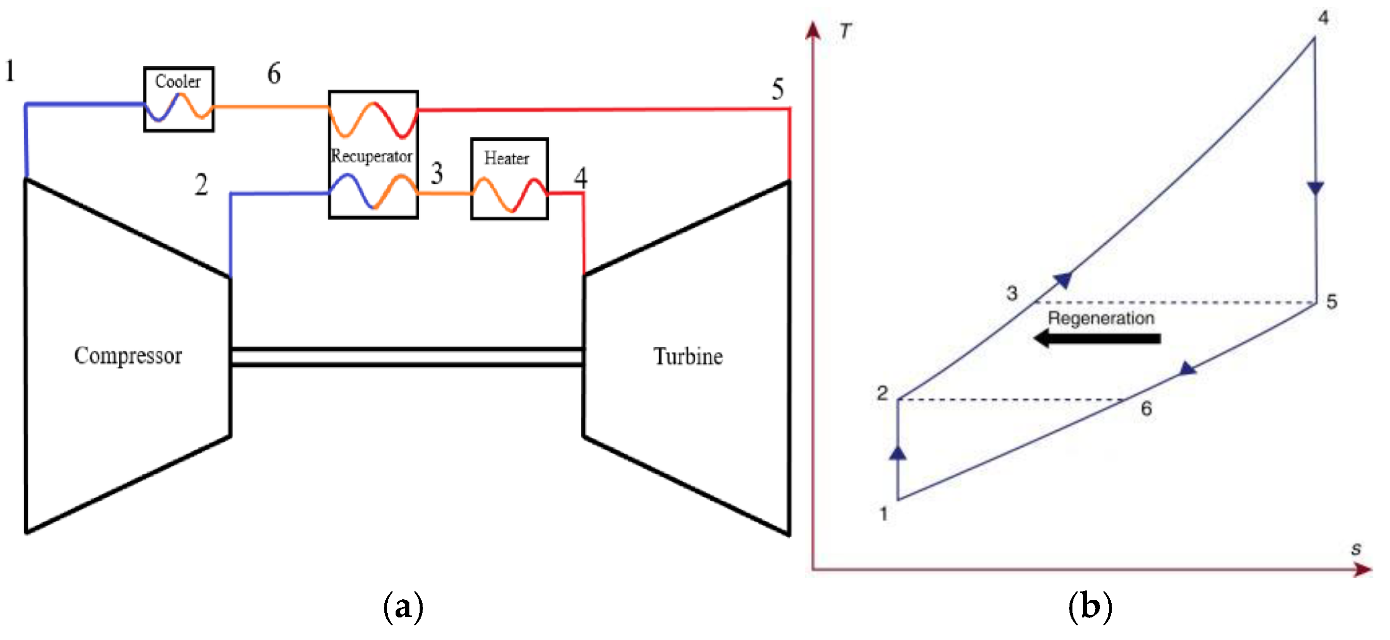
Figure 2.
(a) Simple SBC (T5<T2). (b) Recuperated SBC (T5>T2).
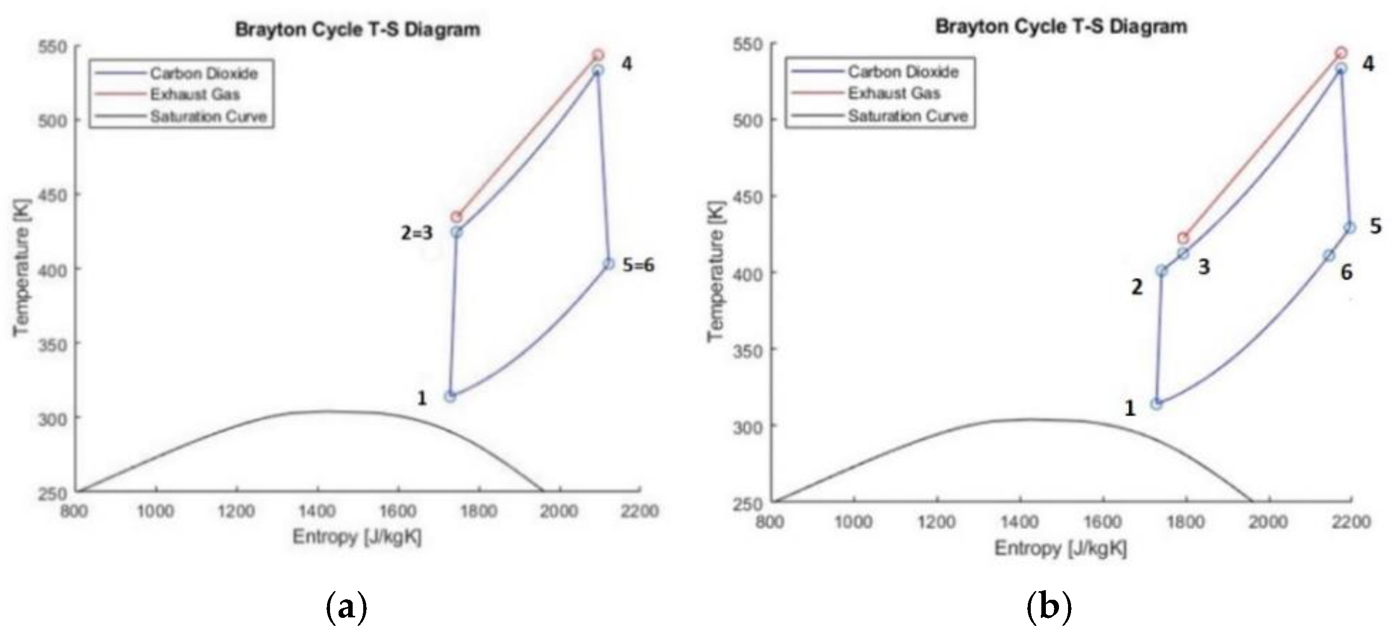
Figure 3.
Net power output of SBC as a function of pressure ratio for the simple cycle (red) and the recuperated cycle (blue).
Figure 3.
Net power output of SBC as a function of pressure ratio for the simple cycle (red) and the recuperated cycle (blue).

Figure 4.
Thermal efficiency of SBC as a function of compressor pressure ratio for the simple cycle (red) and the recuperated cycle (blue).
Figure 4.
Thermal efficiency of SBC as a function of compressor pressure ratio for the simple cycle (red) and the recuperated cycle (blue).
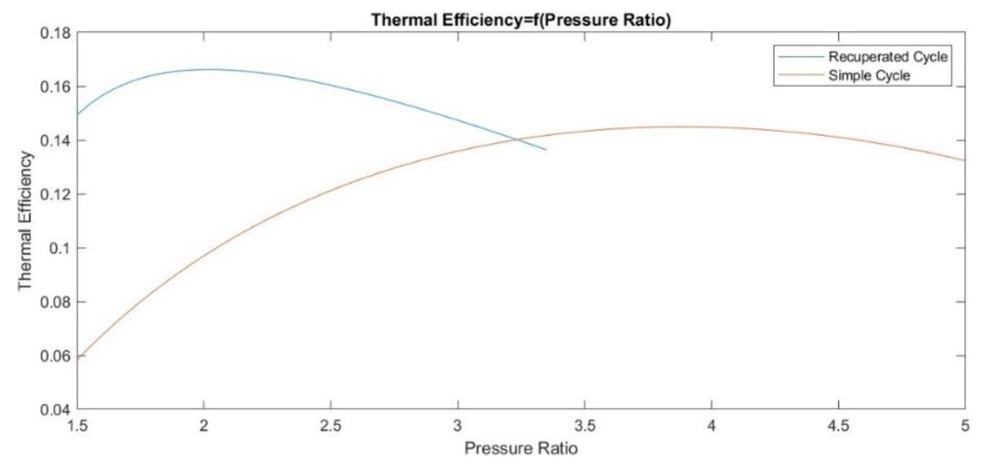
Figure 5.
Exhaust gas temperature at the heater outlet as a function of the compressor pressure ratio for a simple cycle (red) and a recuperated cycle (blue).
Figure 5.
Exhaust gas temperature at the heater outlet as a function of the compressor pressure ratio for a simple cycle (red) and a recuperated cycle (blue).
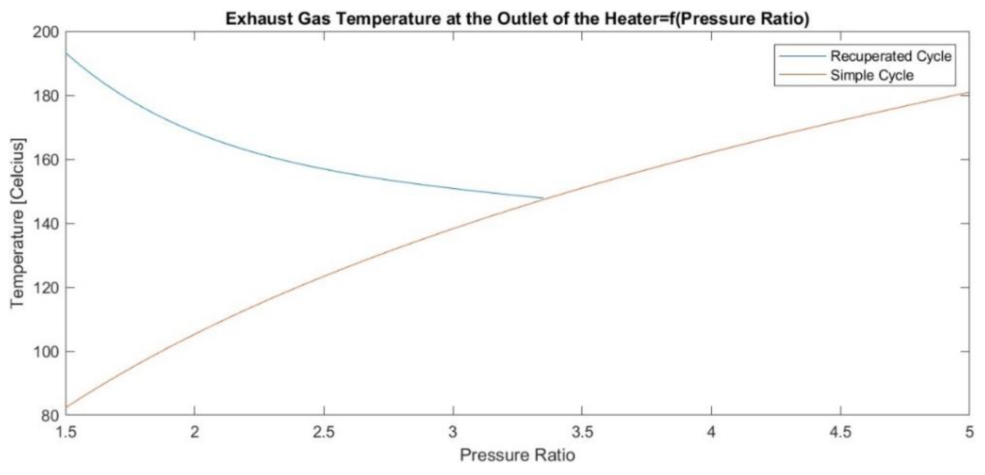
Figure 6.
Calculated carbon dioxide mass flowrate as a function of the compressor pressure ratio for a simple cycle (red) and a recuperated cycle (blue).
Figure 6.
Calculated carbon dioxide mass flowrate as a function of the compressor pressure ratio for a simple cycle (red) and a recuperated cycle (blue).
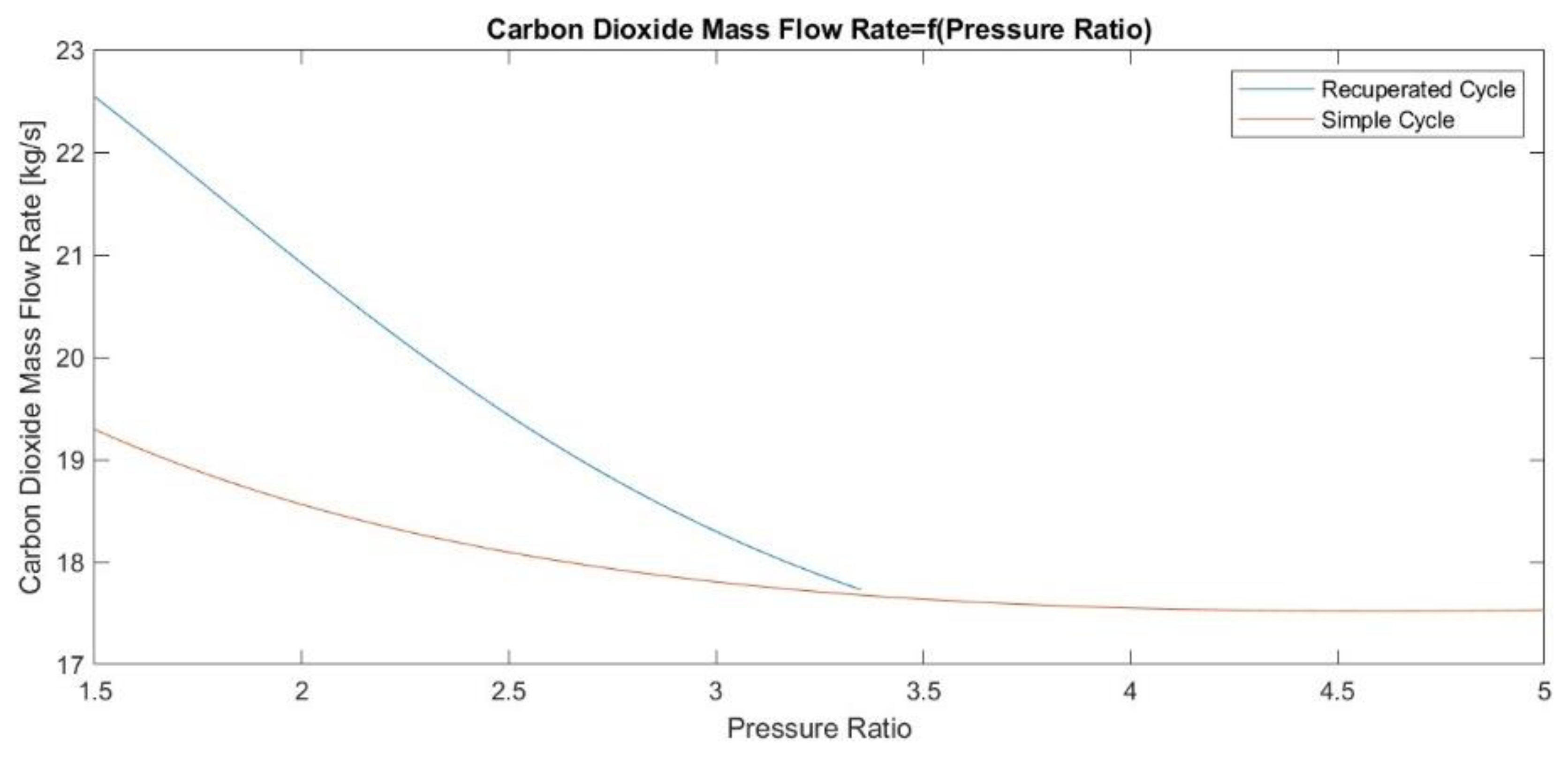
Figure 7.
Temperature-entropy diagram of the SBC for the optimal pressure ratio.
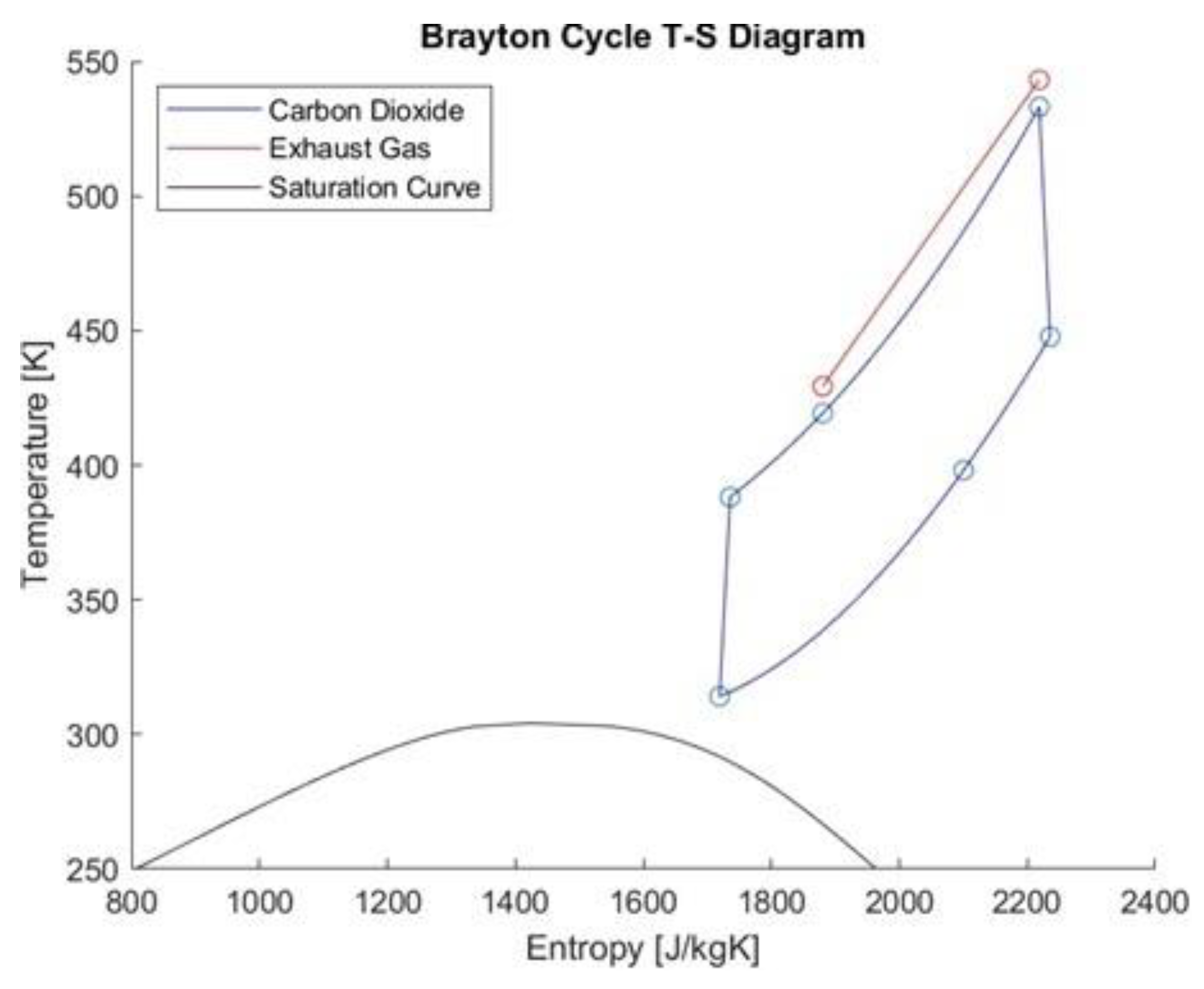
Figure 8.
(a) Net power output of SBC as a function of main engine load. (b) Thermal efficiency of SBC as a function of the main engine load.
Figure 8.
(a) Net power output of SBC as a function of main engine load. (b) Thermal efficiency of SBC as a function of the main engine load.
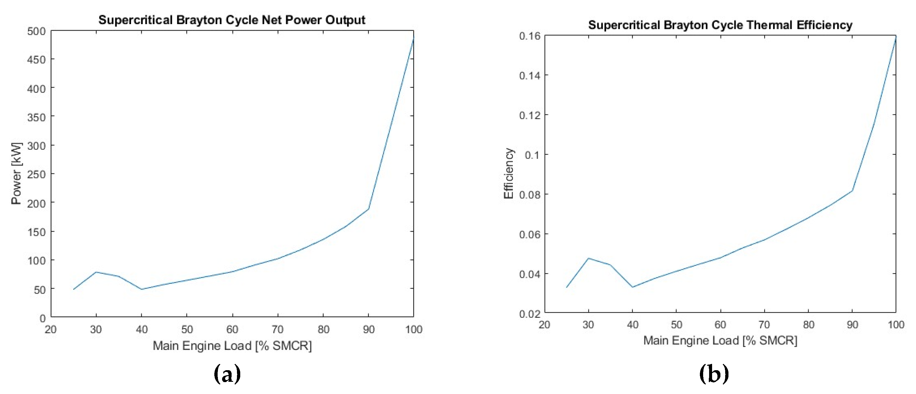
Figure 9.
(a) Percentage increase in overall net power output and thermal efficiency due to the use of SBC for WHR. (b) Corresponding percentage reduction of SFOC due to WHR by means of SBC.
Figure 9.
(a) Percentage increase in overall net power output and thermal efficiency due to the use of SBC for WHR. (b) Corresponding percentage reduction of SFOC due to WHR by means of SBC.
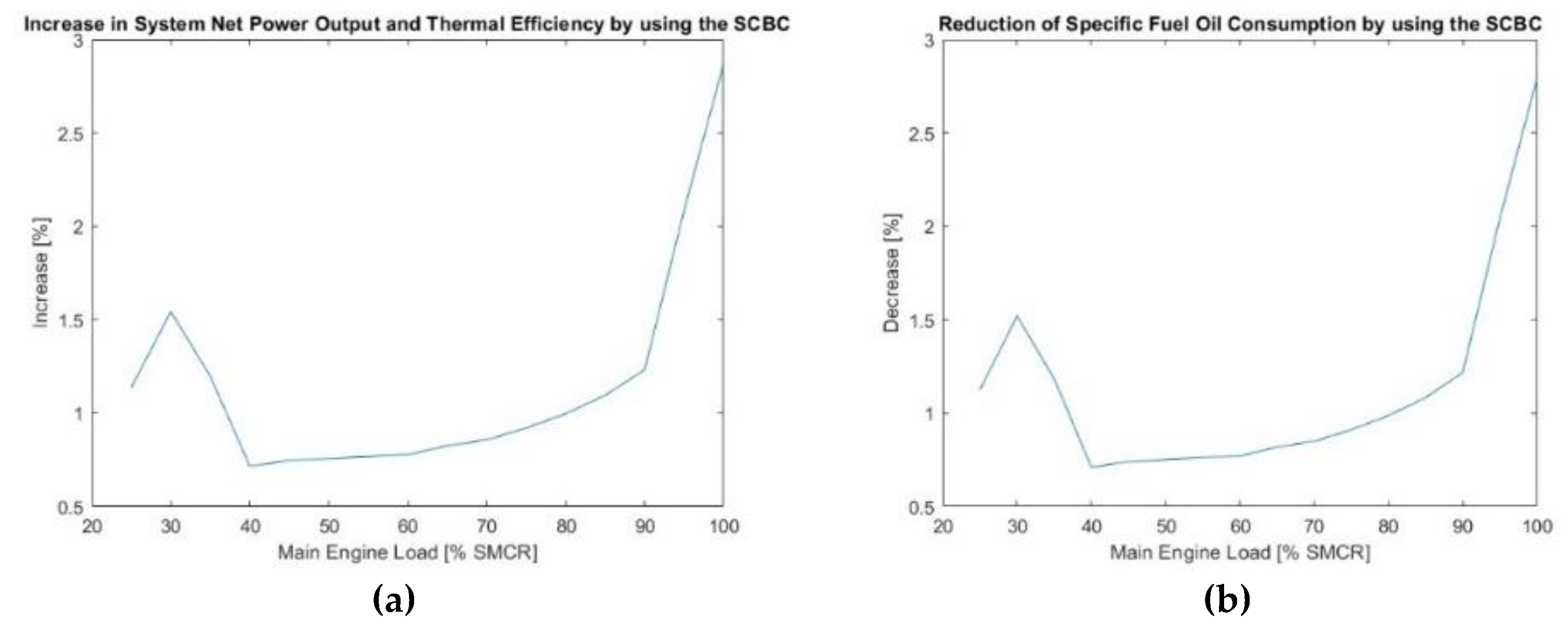
Figure 10.
(a) Variation of the combined cycle power against load. (b) Variation of the combined cycle thermal efficiency against load.
Figure 10.
(a) Variation of the combined cycle power against load. (b) Variation of the combined cycle thermal efficiency against load.
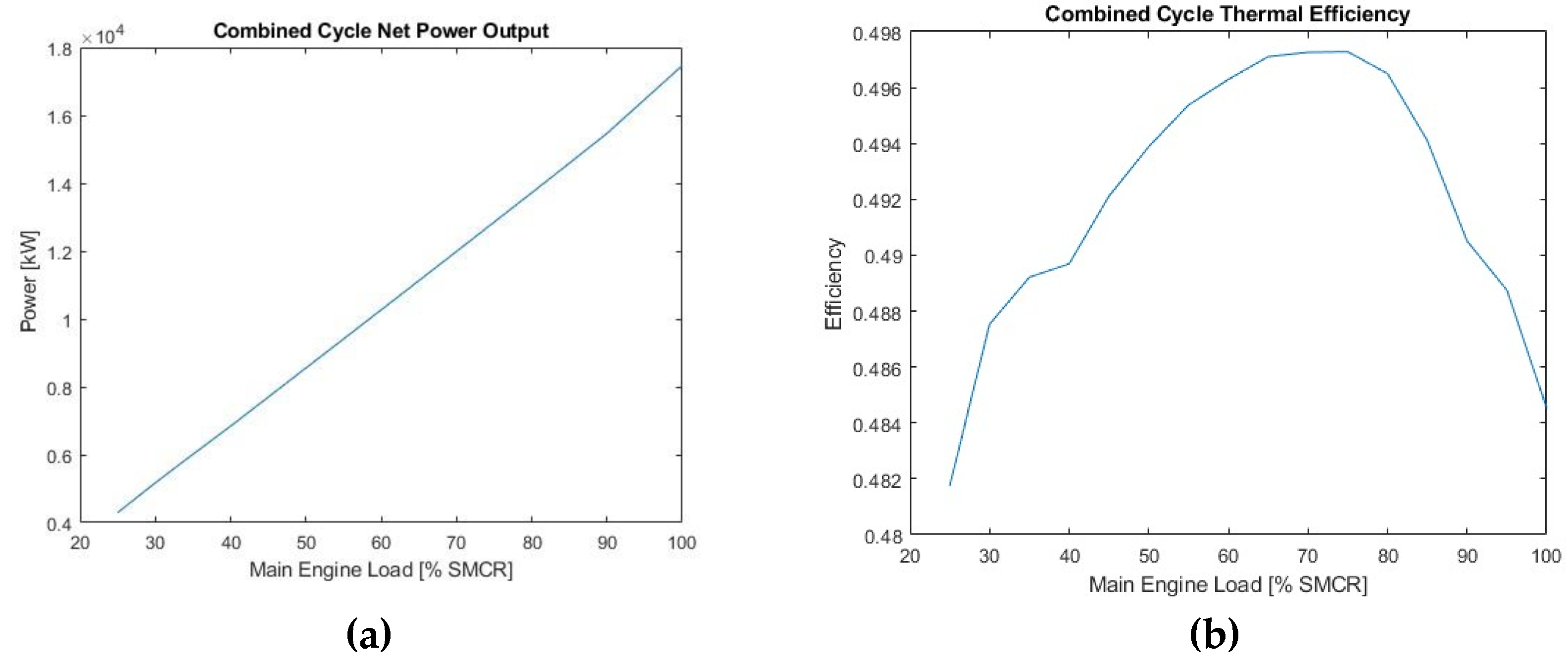
Figure 11.
(a) Effect of main engine power in the available waste heat rate. (b) Effect of main engine power in the power recovered by the SBC.
Figure 11.
(a) Effect of main engine power in the available waste heat rate. (b) Effect of main engine power in the power recovered by the SBC.
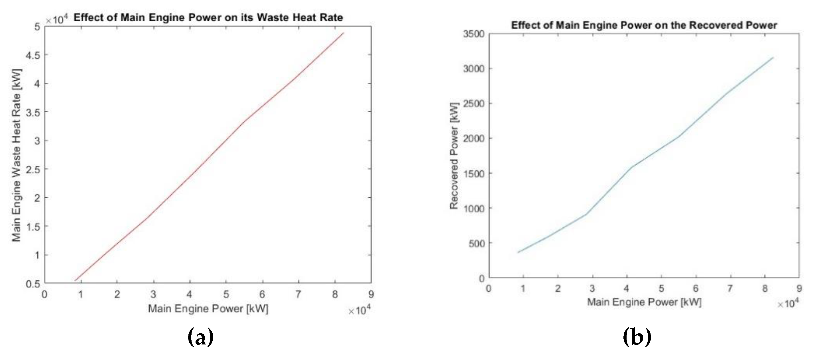
Figure 12.
(a) Effect of main engine power in the predicted compressor optimal pressure ratio. (b) Effect of main engine power in the percentage contribution of SBC in overall CC power output.
Figure 12.
(a) Effect of main engine power in the predicted compressor optimal pressure ratio. (b) Effect of main engine power in the percentage contribution of SBC in overall CC power output.
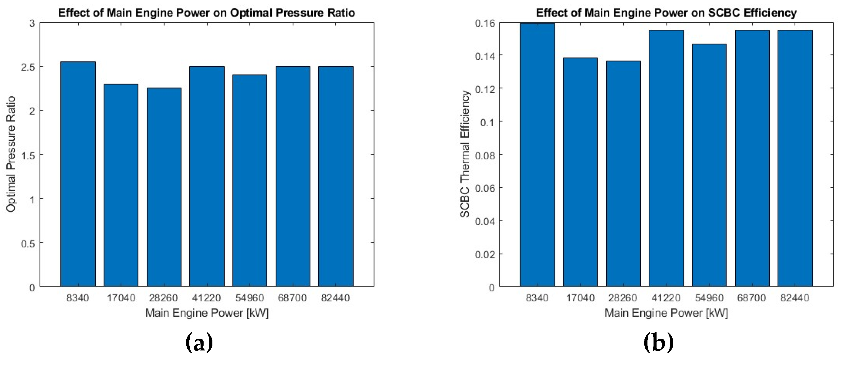
Table 3.
Characteristics of RSBC, main engine and CC for the optimal pressure ratio.
| RSBC | Main Engine | Combined Cycle |
| Pressure ratio 2.55 | Load 100% | Power 17468 kW |
| Min pressure 7.577 MPa | Power 16980 kW | Thermal efficiency 0.47 |
| Max pressure 19.322 MPa | SFOC 179 g/kWh | SFOC 174 g/kWh |
| Min temperature 40.98 oC | Gas flowrate 23.4 kg/s | Gas temperature 156 oC |
| Max temperature 19.322 oC | Gas temperature 270 oC | Efficiency increase 2.873% |
| Power 488 kW | Thermal efficiency 0.47 | Power increase 2.873% |
| Thermal efficiency 0.159 | SFOC reduction 2.792% | |
| CO2 mass flowrate 12.299 kg/s | ||
| Heat input rate 3063.1 kW | ||
| Heat recuperation rate 1115 kW | ||
| Cooling rate 2575.32 kW | ||
| Heater effectiveness 0.919 | ||
| Recuperator effectiveness 0.832 |
Table 4.
MAN ME-GI Marine Engine Characteristics (EGA= Exhaust Gas Amount, EGT=Exhaust Gas Temperature) [12].
Table 4.
MAN ME-GI Marine Engine Characteristics (EGA= Exhaust Gas Amount, EGT=Exhaust Gas Temperature) [12].
| Model | Power [kW] | SFOC [g/kWh] | EGA [kg/s] | EGT[oC] |
| 6G45ME-C9.5-GI-HPSCR | 8340 | 172 | 17.4 | 270 |
| 6G60ME-C10.5-GI-HPSCR | 17040 | 167 | 36.4 | 245 |
| 6G80ME-C10.5-GI-HPSCR | 28260 | 162 | 58.5 | 242 |
| 6G95ME-C10.5-GI-LPSCR | 41220 | 161 | 79.4 | 265 |
| 8G95ME-C10.5-GI-LPSCR | 54960 | 165 | 112.4 | 255 |
| 10G95ME-C10.5-GI-LPSCR | 68700 | 161 | 132.4 | 265 |
| 12G95ME-C10.5-GI-LPSCR | 82440 | 161 | 158.9 | 265 |
Disclaimer/Publisher’s Note: The statements, opinions and data contained in all publications are solely those of the individual author(s) and contributor(s) and not of MDPI and/or the editor(s). MDPI and/or the editor(s) disclaim responsibility for any injury to people or property resulting from any ideas, methods, instructions or products referred to in the content. |
© 2025 by the authors. Licensee MDPI, Basel, Switzerland. This article is an open access article distributed under the terms and conditions of the Creative Commons Attribution (CC BY) license (http://creativecommons.org/licenses/by/4.0/).
Copyright: This open access article is published under a Creative Commons CC BY 4.0 license, which permit the free download, distribution, and reuse, provided that the author and preprint are cited in any reuse.


