
Submitted:
09 December 2025
Posted:
10 December 2025
You are already at the latest version
Abstract
A co-extrusion system, consisting of two sequential impregnation modules equipped with two heating systems, has been developed aimed at forming carbon yarns impregnated with thermoplastics. It has been shown that to ensure complete impregnation of the formed yarn, it is necessary to maintain the temperature in the extruders at 60-80 °C above the melting temperature of the polymer used. The highest strength achieved in the impregnated yarns was 3.3 GPa, which is 67% of the strength of raw carbon fiber. The degree of strength attained is determined primarily by the viscosity of the polymer melt; the minimum strength of 2.3 GPa and the greatest damage to the carbon fiber during impregnation was observed with the most viscous polymer. For all the studied samples, the elastic modulus is 210-220 GPa, which indicates good orientation and uniform drawing, allowing the rigidity of the raw carbon fiber to be almost completely realized.
Keywords:
carbon fibers
; interfaces
; surface modification
; co-extrusion impregnation
; thermoplastics
; polypropylene
; ethylene-vinyl acetate
; mechanical properties
1. Introduction
Additive manufacturing (AM), commonly known as 3D printing (ASTM F 2792), is a rapidly developing group of methods for creating finished products by applying material to a substrate. This method is fundamentally different from traditional formative (casting/stamping/deformation) and subtractive (removing excess material from a monolithic workpiece) manufacturing. Additive manufacturing is carried out using equipment with computer numerical control (CNC) called printers (in the case of stereolithography (SLA), selective laser sintering (SLS), fused deposition modeling (FDM), direct ink writing (DIW) etc. printing) or routers (in the case of automated fiber placement (ATP)). Since its inception in the early 1980s [1,2], AM has undergone significant development from the concept and idea stage to widespread use in unique and small-scale production, as well as in hobby projects [1]. The simplest, most affordable, and widely used AM technology is FDM [1,2], based on the hot extrusion of a polymer thread (filament). The technology's availability stems from the advent of the Replicating Rapid Prototyper (RepRap) project in 2005 [2], and the expiration of its patent in 2012. The developments of the RepRap project form the basis of most modern printers.
A significant advantage of AM is the ability to create parts with complex surface geometries [3] from various materials [4] with minimal waste [4,5]. Furthermore, parts produced using FDM technology are anisotropic [3]. These properties of AM allow for the rapid and active implementation of biomimetic structures—structures that mimic natural structures—with predetermined properties [5], which have significant potential [3]. High speed of product introduction into production and low waste allow for cost reduction in the production of small-scale or unique items in demand in the aerospace, machine tool and automotive industries, medicine and transplantation, as well as art and education [3].
Despite the high potential of AM, a significant portion of FDM-produced items are used as full-scale prototypes [3] due to the low performance characteristics of the polymeric materials used—primarily general-purpose thermoplastics. Such materials include acrylonitrile-butadiene-styrene (ABS) [3], polylactide (PLA) [3], polyethylene terephthalate glycol (PETG), polypropylene (PP), polystyrene (PS), polyvinyl alcohol (PVA), and ethylene vinyl acetate (EVA) [5]. The prevalence of these polymers is due to their low processing temperatures (up to 250°C) and relatively low cost. However, their poor performance characteristics preclude the creation of functional products operating under load.
The creation of functional products in industry has traditionally been associated with structural (engineering) thermoplastics, represented in AM by polycarbonate (PC) and its blends [3], as well as various polyamides (PA) [3,5]. The latter are most frequently used for the manufacture of functional products, but they are characterized by low chemical resistance and high water absorption, which leads to a significant reduction in the properties of products made from them during storage or atmospheric use. Polycarbonates, traditionally processed into products by extrusion, are underrepresented in AM due to their high coefficient of thermal expansion and the associated thermal deformations and delaminations in finished products. At the same time, impact-resistant mixtures of PC with ABS or high-strength and chemical-resistant mixtures based on superstructural PEI are considered promising.
AM using superstructural thermoplastics, such as polyarylene ether ketones (PAEK), polyphenylene sulfide (PSU) [6], and polyetherimide (PEI) [5] is of interest to researchers. They exhibit the highest strength, rigidity, and resistance to chemical and abrasive influences, but are also highly expensive [5]. The use of these polymers is associated with a number of difficulties: most commercially available equipment is not designed to work with them [5], and the polymers themselves exhibit significant adhesion to metals and glass, which are often found in printer designs. Printing with superstructural thermoplastics is also associated with problems of interlayer adhesion, adhesion to substrates, dimensional stability, and thermal oxidation.
A significantly greater increase in the physical and mechanical properties of the material can be achieved by filling of polymer matrix with discrete (short) fibers. This solution is popular in both traditional and additive manufacturing [7] due to its applicability to a variety of manufacturing methods [7]. In AM, this solution is used to produce strong, rigid, impact-resistant, and wear-resistant parts without the need for expensive tooling and multiple manufacturing operations [7]. In such materials, the main factor determining the final level of properties is the fiber length [3,7] - when the composite fails, short fibers are torn out of the matrix polymer without being damaged [3,7]. This is partly due to the low adhesion of pure thermoplastics to the fiber surface [7], which can be addressed by both fiber processing and polymer functionalization. In addition to the length of individual fibers, the properties of the composite are determined by the uniformity of their distribution over the volume and length of the composite filament [3]. Knowledge of these characteristics allows us to predict the behavior of the material under load [7]. High porosity, inherent in polymer composites with short fibers [3,7] and resulting from the high viscosity of thermoplastic polymer melts [7], significantly reduces the final level of material characteristics. Porosity is observed both in the volume of the material and in the interlayer space, which negatively affects the properties of the final products [3,7,8]. Nevertheless, PCMs based on thermoplastics filled with dispersed fiber are attractive from the point of view of the speed of manufacture, repair and processing of products, which distinguishes them favorably from PCMs based on thermosets, the production of which requires the use of thermosetting agents, while they are characterized by a long curing time [7].
Most continuous carbon fiber-reinforced composites are created using the FDM process, while other innovative processes are under development. Fibers can be injected coaxially to produce filaments suitable for commercial FDM machines. Several technologies exist for printing such materials, both thermoplastic and thermosetting [8]. As with short fibers, additively manufactured composites with continuous fibers tend to contain a higher proportion of pores (5-15% by volume) compared to traditionally produced composites. This porosity is related to the composite nature of the filaments, the additional impregnation of the fibers in the nozzle, and the FDM process itself. Porosity can be reduced by post-processing [7].
Moreover, the mechanical properties of materials reinforced with continuous fibers are significantly higher than those filled with short fibers, as the fiber lengths significantly exceed the critical length for fiber-polymer systems. This makes high fiber filling levels in materials achievable [8]. This field is still in its infancy, and research is primarily focused on proving the viability of ideas or fundamentally investigating the properties and structure of materials. There is also some amount of work on the applications and design of additively manufactured products made from reinforced plastics [7,9].
There are several publications on the impregnation of continuous fiber bundles directly in the nozzle with PLA melt. For example, a series of composites based on PLA reinforced with carbon and jute fibers were printed using the FDP method with in-nozzle impregnation [10]. The volume fractions of fibers were 6.6 and 6.1%, respectively. The strength and elasticity of carbon-filled PLA were 185.2 MPa and 19.5 GPa, respectively, with an increase of 435 and 5.9% for pure PLA [10].
In [11], continuous carbon fibers were impregnated with PLA in the nozzle of an FDP printer for the production of carbon-plastic components. The maximum achieved fiber filling was 27% by volume, and the composite demonstrated a strength and flexural modulus of 335 MPa and 30 GPa, respectively. The flexural strength of the composite could be controlled by printing parameters. Simple geometric bodies, such as a hollow cylinder and an aileron, were printed to demonstrate the printer's capabilities and the quality of the resulting parts. In a subsequent study, the composites were also recycled, with 100% of the carbon fiber and 73% of the polylactide matrix recovering [12]. The carbon fiber showed no reduction in properties, while the recycled composites showed a slight increase in physical and mechanical properties compared to the original materials.
In [13], PLA-based carbon fiber reinforced plastics were produced using an FDP process with infiltration directly in the print head, with particular attention paid to fiber pretreatment. In [14], highly filled (up to 52% fiber by volume) FDP-printed PLA-based carbon fiber reinforced plastics were studied. It is worth noting that the samples in this study were 3D trusses printed out of plane. The paper discussed the issues of formation of the printing path, microstructure and the nature of the reaction of the obtained sandwich samples to compressive loads [15].
Achieving complete wetting and impregnation of carbon fibers with thermoplastic melts is difficult without conditions including high pressures and temperatures. It is very difficult to achieve such conditions using impregnation directly in the nozzle. In addition to impregnation in the nozzle, PLA-based carbon fiber filaments were produced using coaxial extrusion molds, followed by processing into parts with simple surface geometry [16]. A similar method was used to produce PLA-based composite filaments for use in FDP printers [17]. In addition to studying microstructure and properties, this work demonstrates the feasibility of out-of-plane printing with reinforced plastics. Although only thin samples were produced in this work, the authors succeeded in producing multiplanar printing with coaxial filaments on a curved substrate [17].
Currently, there are only two manufacturers of commercially available 3D printers for printing with polymers filled with continuous filaments: Markforged and Anisoprint LLC [18]. Desktop Metal™ announced the completion of its industrial-grade hybrid printer, Fiber™, capable of producing parts with properties comparable to traditionally manufactured products. It utilizes a traditional FDM head for printing short-fiber materials and a micro-automated film placement head (μAFP) that lays down 3-mm continuous fiber ribbons similar to a conventional large-format AFP printer. These ribbons will be compacted using a hot compaction roller. Very little information is currently available on this system, but it is likely that the machine will only be able to lay ribbons along very simple paths. Robotic (multi-axis) AM systems producing parts from continuously reinforced composites are also available on the market. One example is an FDM head mounted on a robotic arm from Ingersoll. This machine uses single-stage coextrusion technology, impregnating carbon fiber PEI bundles directly in the nozzle. Orbital Composites also launched the Orb 1 [19], a six-degree-of-freedom robotic arm AM system designed for printing continuously reinforced composites.
Markforged's FDM printers produce parts from unfilled nylon, as well as nylon filled with chopped carbon or continuous fiber. Filling rates of glass, carbon, or polyamide (Kevlar) [20,21] continuous fiber are approximately 30-40% by volume. The mechanical properties and microstructure of printed samples were studied in [22,23,24]. Markforged printers use a 0.4 mm diameter composite filament with a nozzle of the same diameter for printing unfilled nylon. Parts printed on these printers with carbon fibers show a tensile strength of ~700 MPa and an elastic modulus of ~50 GPa. Anisoprint LLC reports similar properties [18]. This level of properties is impressive compared to unfilled polymers, but significantly inferior to traditional PCMs. The literature contains information on several alternative approaches to AM manufacturing of composites. Some of these lead to a slight increase in properties relative to the original polymer [25,26,27,28]. Others, such as μAFP or direct energy deposition (DED), specialize in a high degree of material filling with continuous carbon fiber (50–60%) and matrices based on superstructural thermoplastics (PEEK, PECK, PEI), which allows for the production of products with particularly high performance characteristics, but with drawbacks relative to the geometry of AM-produced products—sharp corners and curved surfaces are impossible in this case. Another approach is LOM (lamination-based manufacturing) technology, which is based on machine cutting of composite prepregs and their layer-by-layer curing under pressure exerted by a system of connecting rollers. This method can produce components with tensile strengths of 668.3 MPa and flexural strengths of 591.16 MPa [29].
Thus, an analysis of the literature suggests that AM with continuous CF could open up new possibilities for the design and production of components with enhanced physical and mechanical properties. Potential for producing components with strength and rigidity comparable to their metallic counterparts could drive its development and expansion in the coming years. Furthermore, integrating geometry optimization into this manufacturing technology could introduce it to the market for highly loaded components. Currently, specialized printing filaments based on discrete or continuous carbon fibers with low densities (less than 1.5 K) are used for 3D printing of carbon fiber-reinforced polymer matrix components. The use of such filaments results in low print speeds for composite materials, significantly increasing costs. Our proposed approach utilizes standard, high-density carbon fibers (12-24 K) for additive manufacturing, enabling a 9-12-fold increase in the speed of 3D printing composite structures.
2. Materials and Methods
2.1. Materials
Umatex UMT49 12K-EP carbon fibers, manufactured by Alabuga-Volokno LLC, with a tensile strength of 4.9 GPa and an elastic modulus of 230 GPa was used in this study. The thermoplastic polymers used to produce the yarn includes polypropylene grades PP H030 GP (general-purpose, injection-molded, melt flow index 230 °C/2.16 kg — 3.0 g/10 min) and PP H270 FF (high-flow, extrusion-grade, melt flow index 230 °C/2.16 kg — 27.0 g/10 min) manufactured by PJSC Sibur, ethylene-vinyl acetate (EVA) copolymer Evatane EVA 28-40, and polypropylene/EVA blends in a 75/25 and 50/50 wt.% ratios.
2.2. Preparation of Composite Yarns
Before impregnation, thermal oxidation of carbon fibers was carried out in the air atmosphere at temperatures of 500 °C for 10 min. The conditions for thermal treatment of carbon fibers were chosen based on our previous investigations, see [30,31].
A pilot setup for two-stage coaxial extrusion was used to produce polymer-impregnated carbon yarns. The system consists of two cylindrical brass impregnation tanks, heated by 500-watt nozzle heaters mounted on them, similar to those used in injection molding machines. The upper tank impregnates the dry tow with polymer as it is drawn through the melt. The fiber path is 200 mm long, with a transition from a smooth 20 mm inner diameter to a threaded hole in the lower face, which is used to secure nozzles as replaceable dies. As the carbon filament is drawn through the upper tank, it is initially impregnated with the polymer melt, and excess polymer is removed by passing it through a standard 3D printing nozzle. However, droplets of excess polymer remain on the impregnated filament, so a second die is used to improve impregnation quality, remove droplets, and achieve the final filament diameter. It also consists of a brass cylinder with a diameter of 25 mm and a length of 50 mm with a conical bore of 20 mm, tapering to a 2 mm wide channel with a threaded hole for attaching a die. To produce impregnated filament samples, 12K carbon filament was passed through the dies, polymer granules were loaded into the upper bath, and the melt and coextruder nozzle temperatures were adjusted by controlling the heaters. After the polymer melted and the melt and components reached the extrusion system, the carbon filament was pulled through the polymer melt. The filament pulling speed was set at 10 mm/s. The resulting filaments had a diameter of 1 mm, and up to 12-15 meters of filament were produced per cycle.
2.3. Characterization
The microstructure of the samples was studied using scanning electron microscopes TESCAN VEGA Compact (Joint stock company, TESCAN, Brno, Czech Republic) and Hitachi TM-1000 (Hitachi Ltd., Japan), in the backscattered electron (Compo BSE) and secondary electron (SE) modes.
A study using Fourier-transform IR spectroscopy with an attenuated total internal reflection (ATIR) attachment with a diamond crystal was conducted. An OPTOSKY ATP8900+ FTIR spectrometer (OPTOSKY Technology Co., Ltd.) was used in the study. Raman spectroscopy Thermo DXR (USA) was conducted with wavelengths of 532 and 780 nm and maximum power of 10 mW and 24 mW, respectively.
A pull-out test method was developed to determine the adhesive interaction of carbon fiber fibers with polymers. A fiber, glued at one end to a paper half-frame, is immersed in a 100-200 micron thick film of polymer melt located on the surface of a thin, hot graphite substrate heated to the polymer's melting point. After cooling and solidification of the polymer, tensile tests were performed by pulling the fiber out of the hardened polymer. Using a Zwick/Roell Z020 universal tensile testing machine equipped with a 100 N force transducer, load-deformation diagrams were recorded, which were used to calculate the adhesive strength of the fiber-matrix interface.
For tensile testing, 220 mm long specimens with a working length of 100 mm and ends sealed in 1 mm thick cardboard protective overlays measuring 52 x 60 mm were cut from the obtained 3D printing filaments. Before sealing them in cardboard frames, the polymer and carbon fiber content of each specimen was determined using an AND GR 202 analytical balance (AND, Japan). The polymer content in the specimen was determined based on the difference between the specimen mass and the fiber mass calculated based on their linear density and specimen length. The strength and deformation properties of the obtained carbon filaments impregnated with thermoplastics were determined using a Zwick/Roell Z020 universal tensile testing machine (Zwick/Roell Group, Ulm, Germany) with a maximum applied force of 20 kN, equipped with a MultiXtens high-precision contact deformation measurement system. The working length of the threads in the grips was 100 mm, the active gripping speed during the test varied from 1 to 100 mm/min, the distance between the deformation measurement points when using the sensor was 70 mm.
3. Results and Discussion
Using FT-IR spectroscopy, the chemical nature of the modified carbon fiber surface was studied. Figure 1 shows the spectrum of the surface of carbon fiber. As can be seen from the FT-IR spectrum, carbonyl and carboxyl functional groups are formed with characteristic IR spectrum lines at 1583 cm-1 and 2702 cm-1. Carbonyl groups are predominantly formed, accounting for up to 60–65% of the total number of functional groups on the surface.
Raman spectra of raw and thermally treated carbon fibers are shown in Figure 2. It was found that at temperatures above 450°C, the structural order of the outer fibrillar shell of the high-strength fiber begins to decrease, as evidenced by a decrease in the intensity of the 2D line in the spectrum by almost an order of magnitude. An increase and broadening of the D and G spectral lines is also observed, with their intensities becoming virtually identical. This indicates the formation of a large number of defects on the carbon fiber surface, resulting in increased surface chemical activity.
Figure 3 show SEM micrographs of modified carbon fibers. It was shown that thermal treatment results in the significant surface roughness of carbon fibers filaments, see micrograph in Figure 3b, obtained with high magnification
Typical appearance of pull-out curve is shown in Figure 4. For polypropylene, typical interface strengths are 22-25 MPa; the interface adhesion strength of Evatane EVA 28-40 is 32-35 MPa; for polypropylene - EVA 28-40 blends, it is 25-28 MPa. Surface treatment of the fiber at temperatures above 450°C increases the adhesion strength by 4-5 MPa.
Figure 5 shows microstructure of filaments of carbon yarn, impregnated with polymers by two-stage coaxial extrusion. It is evident that by maintaining the temperature in the coextruders 60-80°C higher than the melting temperature of the polymer used, it was possible to ensure complete impregnation of the thread with the polymer.
Tensile tests were conducted on filament samples, and load-strain diagrams were obtained (Figure 6). The ultimate tensile strength, tensile modulus, and elongation at break were determined depending on the polymer type (see Table 1), surface treatment conditions, and extrusion temperature conditions.
The use of a coextrusion system allowed for a high degree of realization of the carbon fiber's strength characteristics in the composite filament. The initial strength of Umatex UMT49 12K-EP fiber is 4.9 GPa, with the highest strength realized on the resulting filaments being 3.3 GPa, which is 67% of the original fiber's strength. The degree of strength realization is primarily determined by the viscosity of the polymer melt; the minimum strength of 2.3 GPa and the greatest damage to the carbon fiber during impregnation are observed on the most viscous polymer, polypropylene grade PP H030. For all the samples studied, the elastic modulus is 210 to 225 GPa, which indicates good orientation and uniform drawing, allowing the rigidity of the original carbon fiber to be almost completely realized.
As follows from Table 1, increase in polypropylene melt flowability nearly has no effect on the effect on the elastic modulus and carbon fiber content in the composite yarn. On the other hand, both tensile strength and elongation and break increasing significantly when using polypropylene with lower viscosity. Additionally it should be noted that mechanical properties of carbon fibers impregnated with PP H270 FF (melt flow index 230 °C/2.16 kg — 27.0 g/10 min) is enough close to those for carbon fibers impregnated with EVA 28-40 at extrusion temperature of 190 0C, melt flow index for EVA 28-40 at this temperature was found to be of 36 g/10 min at the same loading [32]. However, fiber content in composite yarn prepared using EVA 28-40 at extrusion temperature of 190 0C was found to be about 80 %. As was observed previously [33] for the same UMT49 carbon fibers impregnated with polysulfone by polymer solution, optimal content of fiber in composite yarns should not exceed 70 wt. %, further increase in fiber content results in a decrease in mechanical properties of yarn. As shown in Table 1, increase in extrusion temperature for EVA 28-40 impregnation from 190 to 220 0C results in a decrease in fiber content in yarn of about 70 wt. %, which is accompanied with increase in tensile strength up to 3,3 GPa. Additionally, it should be noted that partial replacing of low-viscosity polypropylene with EVA in the polymer matrix does not results in any changes in yarn mechanical properties within the measurement error. Thus, it should be concluded that mechanical properties of carbon yarns impregnated with thermoplastic polymers by coextrusion are determined by the viscosity of the polymer melt, which can be adjusted by varying the extrusion temperature.
4. Conclusions
Carbon yarns impregnated with thermoplastics were prepared using coextrusion system, consisting of two sequential impregnation modules equipped with two heating systems. The highest strength achieved in the impregnated yarns was found to be of 3.3 GPa, which is 67% of the strength of raw carbon fiber. The degree of strength attained is determined primarily by the viscosity of the polymer melt; the minimum strength of 2.3 GPa and the greatest damage to the carbon fiber during impregnation was observed with the most viscous polymer. For all the studied samples, the elastic modulus was found to be between 210 and 225 GPa, which indicates good orientation and uniform drawing, allowing the rigidity of the raw carbon fiber to be almost completely realized. It was concluded that that mechanical properties of carbon yarns impregnated with thermoplastic polymers by coextrusion are determined by the polymer melt viscosity, which can be adjusted by varying the extrusion temperature.
Author Contributions
Project administration, Conceptualization, V.V.T.; methodology, A.A.S.; investigation, Y.V.O., and A.A.S.; writing—original draft preparation, V.V.T.; writing—review and editing, V.V.T. All authors have read and agreed to the published version of the manuscript.
Funding
The study was supported by RSCF grant no 24-19-00822.
Institutional Review Board Statement
Not applicable.
Data Availability Statement
The data presented in this study are available on request from the corresponding author.
Conflicts of Interest
The authors declare no conflicts of interest.
References
- Kabir, S.M.F.; Mathur, K.; Seyam, A.-F.M.S. A critical review on 3D printed continuous fiber-reinforced composites: History, mechanism, materials and properties. Compos. Str. 2020, 232, 111476. [Google Scholar] [CrossRef]
- Blanco, I. The use of composite materials in 3D printing. J. Compos. Sci. 2020, 4, 42. [Google Scholar] [CrossRef]
- Wang, X.; Jiang, M.; Zhou, Z.; Gou, J.; Hui, D. 3D printing of polymer matrix composites: A review and prospective. Compos. B. 2017, 110, 442–458. [Google Scholar] [CrossRef]
- Silva, M.R.; Pereira, A.M.; Alves, N.; Mateus, G.; Mateus, A.; Malça, C. Development of an additive manufacturing system for the deposition of thermoplastics impregnated with carbon fibers. J. Manufact. Mater. Process. 2019, 3, 35. [Google Scholar]
- Valino, A.D.; Dizon, J.R.C.; Espera, A.H.; Chen, Q.; Messman, J.; Advincula, R.C. Advances in 3D printing of thermoplastic polymer composites and nanocomposites. Progr. Polym. Sci. 2019, 98, 101162. [Google Scholar] [CrossRef]
- Miao, Z.; Seo, J.; Hickner, M.A. Solvent-cast 3D printing of polysulfone and polyaniline composites. Polymer 2018, 152, 18–24. [Google Scholar] [CrossRef]
- van de Werken, N.; Tekinalp, H.; Khanbolouki, P.; Ozcan, S.; Williams, A.; Tehrani, M. Additively manufactured carbon fiber-reinforced composites: State of the art and perspective. Addit. Manufact. 2020, 31, 100962. [Google Scholar] [CrossRef]
- Stepashkin, А.А.; Chukov, D.I.; Senatov, F.S.; Salimon, A.I.; Korsunsky, A.M.; Kaloshkin, S.D. 3D-printed PEEK-carbon fiber (CF) composites: Structure and thermal properties. Compos. Sci. Tech. 2018, 164, 319–326. [Google Scholar] [CrossRef]
- Rimašauskas, M.; Kuncius, T.; Rimašauskienė, R.; Simokaitis, T. Evaluation of Conditions for Self-Healing of Additively Manufactured Polymer Composites with Continuous Carbon Fiber Reinforcement. J. Manufact. Mater. Process. 2025, 9, 179. [Google Scholar] [CrossRef]
- Matsuzaki, R.; Ueda, M.; Namiki, M.; Jeong, T.K.; Asahara, H.; Horiguchi, K.; Nakamura, T.; Todoroki, A.; Hirano, Y. Three-dimensional printing of continuous-fiber composites by in-nozzle impregnation. Sci. Rep. 2016, 6, 23058. [Google Scholar] [CrossRef] [PubMed]
- Tian, X.; Liu, T.; Yang, C.; Wang, Q.; Li, D. Interface and performance of 3D printed continuous carbon fiber reinforced PLA composites. Compos. A. 2016, 88, 198–205. [Google Scholar] [CrossRef]
- Tian, X.; Liu, T.; Wang, Q.; Dilmurat, A.; Li, D.; Ziegmann, G. Recycling and remanufacturing of 3D printed continuous carbon fiber reinforced PLA composites. J. Clean. Prod. 2017, 142, 1609–1618. [Google Scholar] [CrossRef]
- Li, N.; Li, Y.; Liu, S. Rapid prototyping of continuous carbon fiber reinforced polylactic acid composites by 3D printing. J. Mater. Process. Technol. 2016, 238, 218–225. [Google Scholar] [CrossRef]
- Bhushan, B.; Caspers, M. An overview of additive manufacturing (3D printing) for microfabrication. Microsyst. Technol. 2017, 23, 1117–1124. [Google Scholar] [CrossRef]
- Liu, S.T.; Li, Y.G.; Li, N.Y. A novel free-hanging 3D printing method for continuous carbon fiber reinforced thermoplastic lattice truss core structures. Mater. Des. 2018, 137, 235–244. [Google Scholar] [CrossRef]
- Hu, Q.; Duan, Y.; Zhang, H.; Liu, D.L.; Yan, B.; Peng, F. Manufacturing and 3D printing of continuous carbon fiber prepreg filament. J. Mater. Sci. 2018, 53, 1887–1898. [Google Scholar] [CrossRef]
- Tse, L.Y.L.; Kapila, S.; Barton, K. Contoured 3D Printing of Fiber Reinforced Polymers. In Proceedings of the 27th Annual International Solid Freeform Fabrication Symposium an Additive Manufacturing Conference, Austin, USA, 8-10 August 2016; 2016; pp. 1205–1216. [Google Scholar]
- Gregory, E.D.; Juarez, P.D. In-situ thermography of automated fiber placement parts. AIP Conf. Proc. 2018, 1949, 060005. [Google Scholar] [CrossRef]
- Orbital Composites introduces Orb 1 industrial-grade robot 3D printer. Available online: https://www.compositesworld.com/news/orbital-composites-introduces-orb-1-industrial-grade-robot-3d-printer (accessed on 20 May 2025).
- van der Klift, F.; Koga, Y.; Todoroki, A.; Ueda, M.; Hirano, Y.; Matsuzaki, R. 3D printing of continuous carbon fibre reinforced thermo-plastic (CFRTP) tensile test specimens. Open J. Compos. Mater. 2016, 6, 18–27. [Google Scholar] [CrossRef]
- Walbran, M.; Turner, K.; McDaid, A.J. Customized 3D printed ankle-foot orthosis with adaptable carbon fibre composite spring joint. Cogent Eng. 2016, 3, 1227022. [Google Scholar] [CrossRef]
- Dickson, A.N.; Barry, J.N.; McDonnell, K.A.; Dowling, D.P. Dowling Fabrication of continuous carbon, glass and Kevlar fibre reinforced polymer composites using additive manufacturing. Addit. Manuf. 2017, 16, 146–152. [Google Scholar]
- Goh, G.D.; Dikshit, V.; Nagalingam, A.P.; Goh, G.L.; Agarwala, S.; Sing, S.L.; Wei, J.; Yeong, W.Y. G. Characterization of mechanical properties and fracture mode of additively manufactured carbon fiber and glass fiber reinforced thermoplastics. Mater. Des. 2018, 137, 79–89. [Google Scholar] [CrossRef]
- Justo, J.; Távara, L.; García-Guzmán, L.; París, F. Characterization of 3D printed long fibre reinforced composites. Compos. Struct. 2018, 185, 537–548. [Google Scholar] [CrossRef]
- Yao, X.; Luan, C.; Zhang, D.; Lan, L.; Fu, J. Evaluation of carbon fiber-embedded 3D printed structures for strengthening and structural-health monitoring. Mater. Des. 2017, 114, 424–432. [Google Scholar] [CrossRef]
- Brooks, H.; Molony, S. Design and evaluation of additively manufactured parts with three dimensional continuous fibre reinforcement. Mater. Des. 2016, 90, 276–283. [Google Scholar] [CrossRef]
- Mori, K.I.; Maeno, T.; Nakagawa, Y. Dieless forming of carbon fibre reinforced plastic parts using 3D printer. Procedia Eng. 2014, 81, 1595–1600. [Google Scholar] [CrossRef]
- Baumann, F.; Scholz, J.; Fleischer, J. Investigation of a new approach for additively manufactured continuous fiber-reinforced polymers. Proc. CIRP 2017, 66, 323–328. [Google Scholar] [CrossRef]
- Parandoush, P.; Zhou, C.; Lin, D. 3D printing of ultrahigh strength continuous carbon fiber composites. Adv. Eng. Mater. 2019, 21, 1800622. [Google Scholar] [CrossRef]
- Stepashkin, A.A.; Chukov, D.I.; Gorshenkov, M.V.; Tcherdyntsev, V.V.; Kaloshkin, S.D. Electron microscopy investigation of interface between carbon fiber and ultra high molecular weight polyethylene. J. Alloys Compd. 2014, 586, S168–S172. [Google Scholar] [CrossRef]
- Chukov, D.; Nematulloev, S.; Zadorozhnyy, M.; Tcherdyntsev, V.; Stepashkin, A.; Zherebtsov, D. Structure, Mechanical and Thermal Properties of Polyphenylene Sulfide and Polysulfone Impregnated Carbon Fiber Composites. Polymers 2019, 11, 684. [Google Scholar] [CrossRef]
- Tcherdyntsev, V.V.; Stepashkin, A.A.; Chukov, D.I.; Olifirov, L.K.; Senatov, F.S. Formation of ethylene-vinyl acetate composites filled with Al–Cu–Fe and Al–Cu–Cr quasicrystallline particles. J. Mater. Res. Tech. 2019, 8, 572–589. [Google Scholar] [CrossRef]
- Stepashkin, A.A.; Mohammad, H.; Makarova, E.D.; Odintsova, Y.V.; Laptev, A.I.; Tcherdyntsev, V.V. Deformation Behavior of Single Carbon Fibers Impregnated with Polysulfone by Polymer Solution Method. Polymers 2023, 15, 570. [Google Scholar] [CrossRef] [PubMed]
Figure 1.
FT-IR spectrum of the surface of modified carbon fiber. Peaks related to RCO-OH (a), RHCOC-H (b), RСO-О- (c) and RСO-О- (d) bonds are indicated.
Figure 1.
FT-IR spectrum of the surface of modified carbon fiber. Peaks related to RCO-OH (a), RHCOC-H (b), RСO-О- (c) and RСO-О- (d) bonds are indicated.
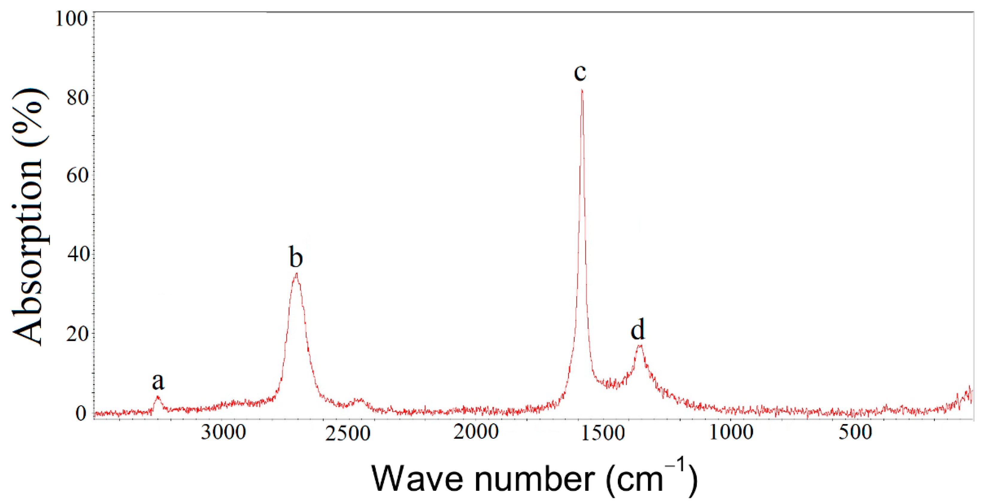
Figure 2.
Raman spectra of (a) raw and (b) modified carbon fibers.
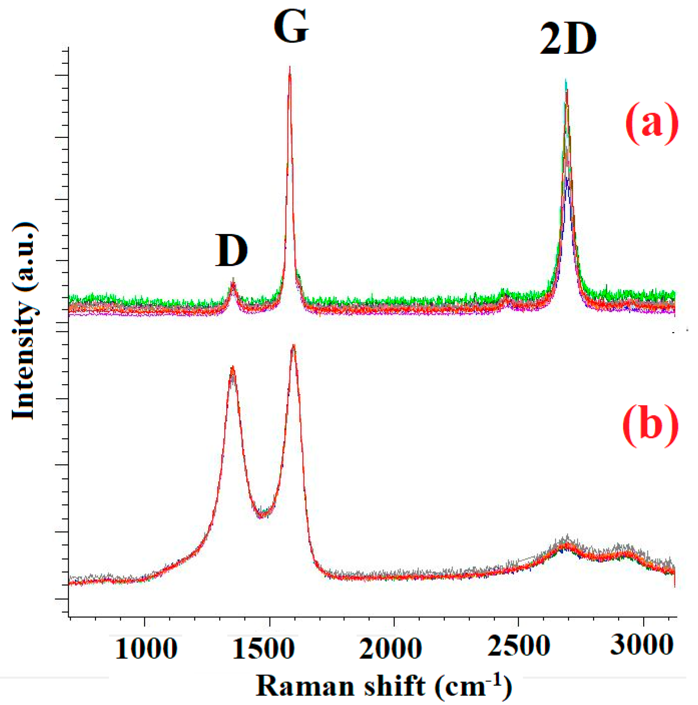
Figure 3.
Surface microstructure of modified carbon fiber.
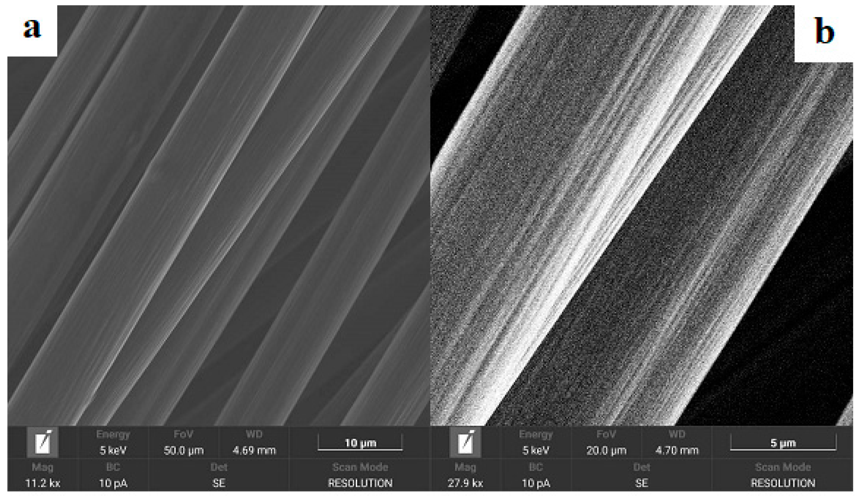
Figure 4.
Load-deformation diagram for single filament pull-out test.
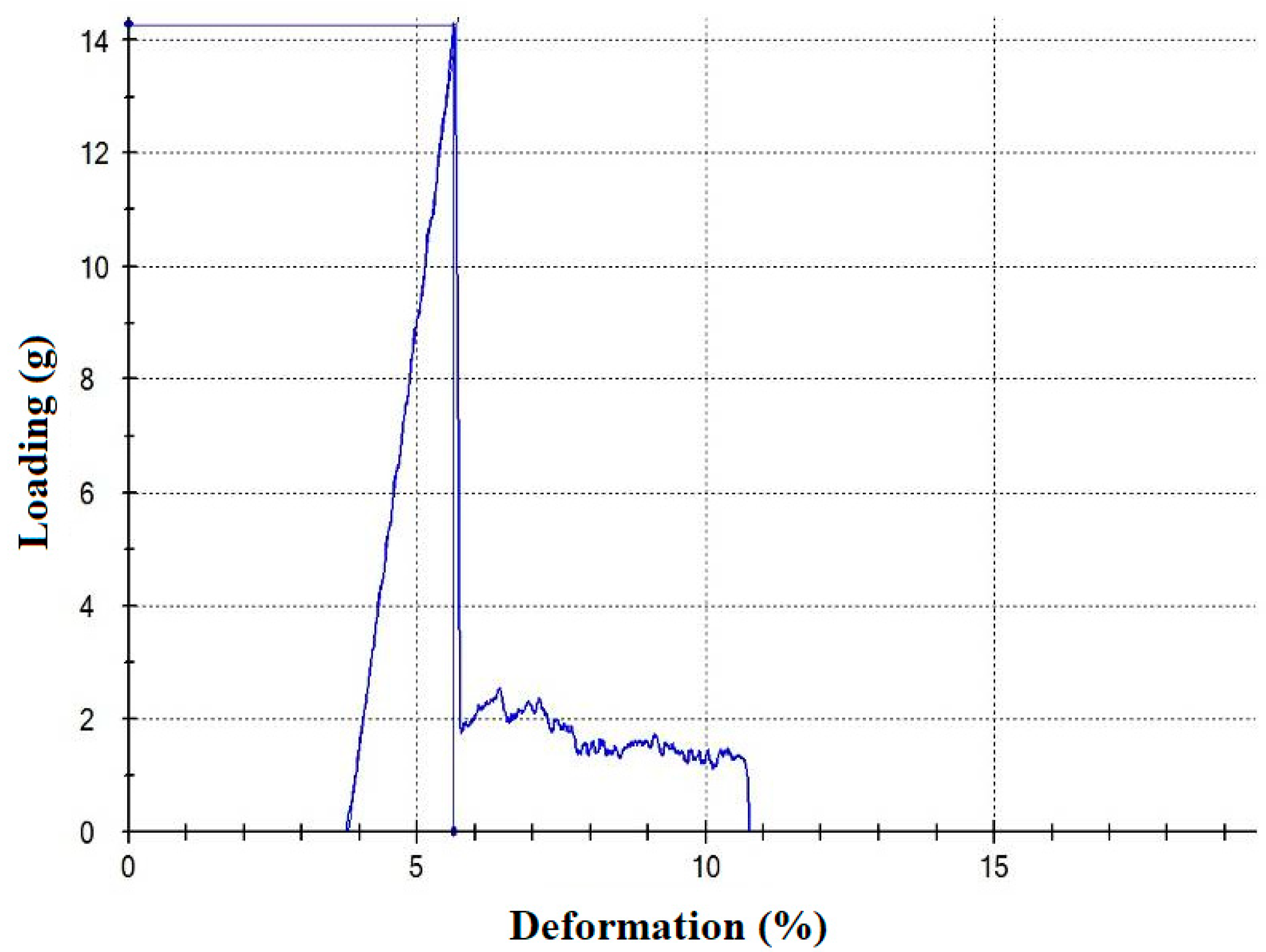
Figure 5.
Microstructure of impregnated filaments.
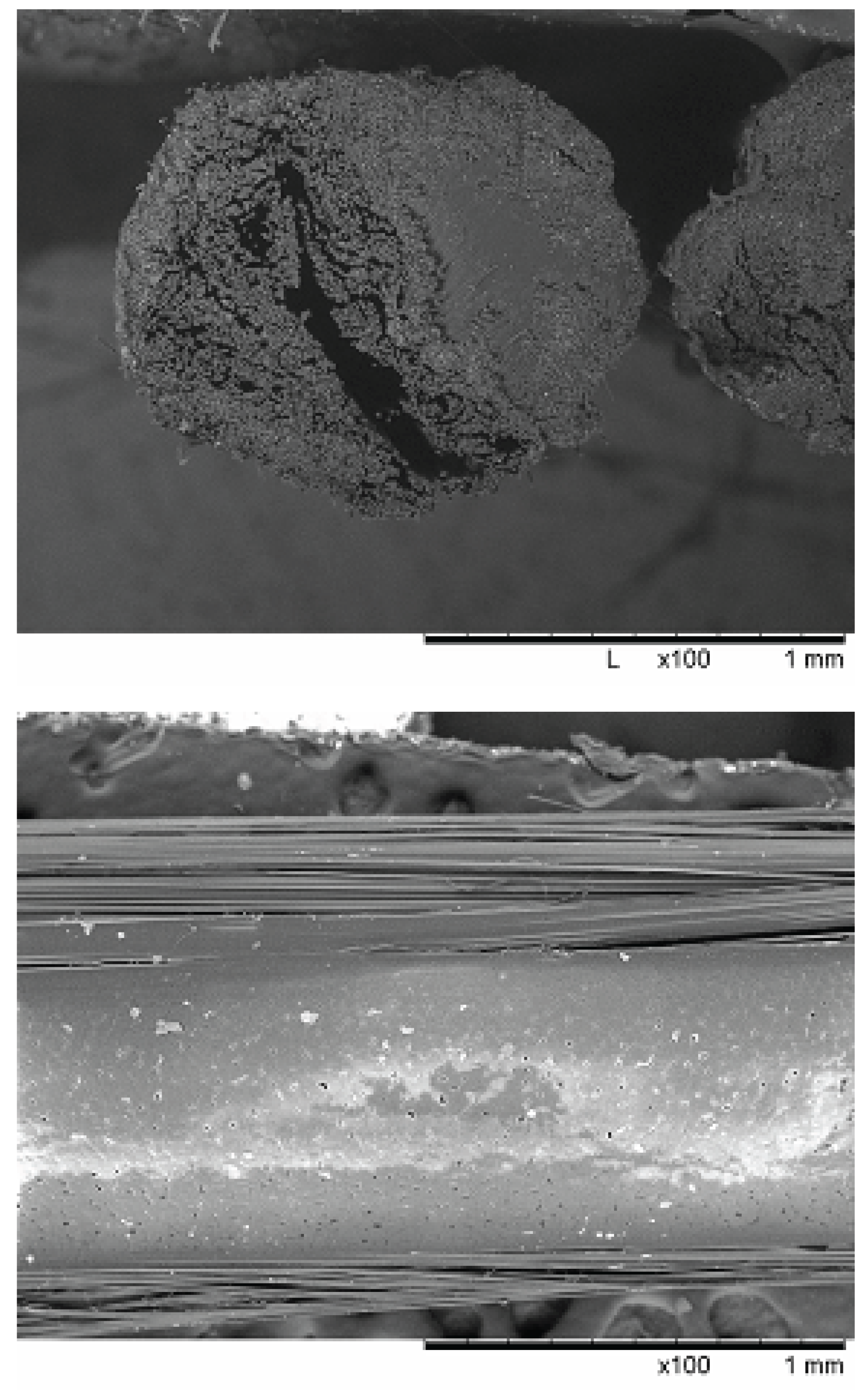
Figure 6.
Typical load-strain tensile curves of carbon fibers impregnated with (a) EVA 28–40 (extrusion temperature of 220 0C) and (b) PP H270 FF polymers.
Figure 6.
Typical load-strain tensile curves of carbon fibers impregnated with (a) EVA 28–40 (extrusion temperature of 220 0C) and (b) PP H270 FF polymers.
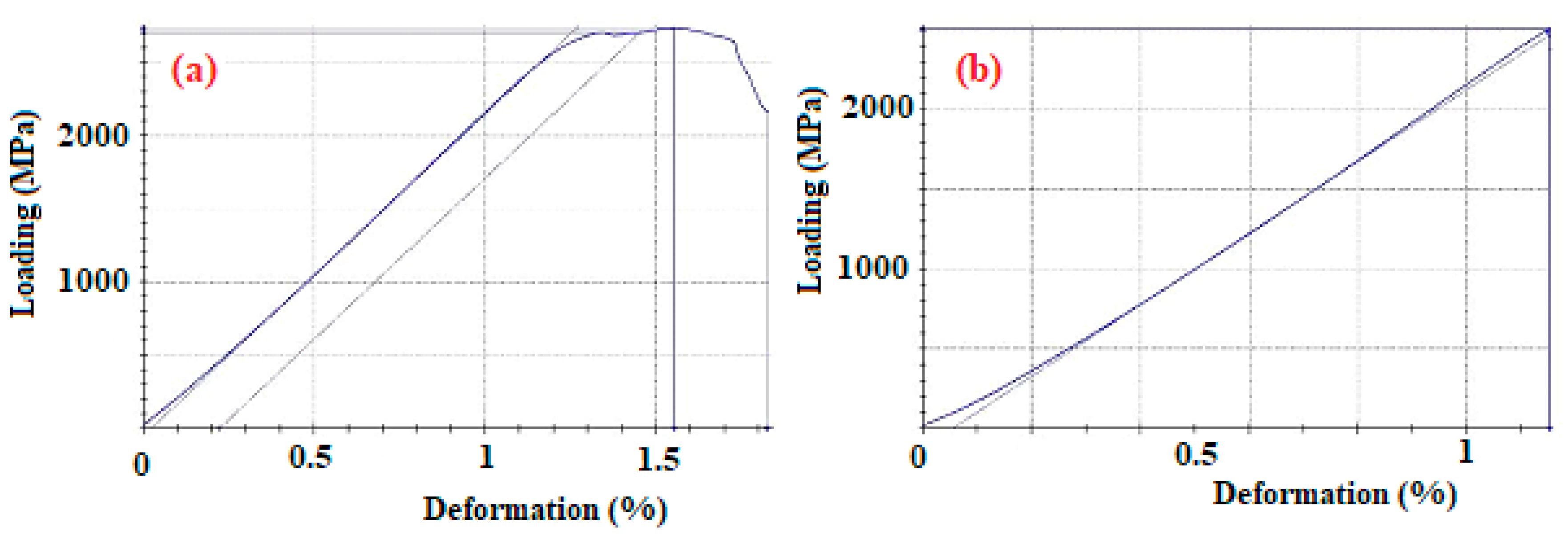

Table 1.
Physical and mechanical properties (elastic modulus E, tensile strength σ, elongation at break ε) and fiber content X for composite carbon yarns impregnated with thermoplastic polymers by coextrusion.
Table 1.
Physical and mechanical properties (elastic modulus E, tensile strength σ, elongation at break ε) and fiber content X for composite carbon yarns impregnated with thermoplastic polymers by coextrusion.
| Matrix polymer | E, GPa | σ,MPa | ε, % | X, % wt. % |
| PP H030 GP (extruded at 190 0C) | 221 ± 2.0 | 2340 ± 271 | 1.08 ± 0.11 | 75.1 ± 1.0 |
| PP H270 FF(extruded at 190 0C) | 223 ± 2.1 | 2942 ± 173 | 1.42 ± 0.06 | 74.4 ± 0.4 |
| EVA 28-40 (extruded at 220 0C) | 225 ± 1.4 | 3312 ± 54 | 1.52 ± 0.05 | 69.9 ± 2.5 |
| EVA 28-40 (extruded at 190 0C) | 218 ± 3.1 | 2825 ± 128 | 1.40 ± 0.11 | 81.1 ± 1.1 |
| PP H270 FF / EVA 28-40 blend 50/50 (extruded at 190 0C) | 218 ± 8.9 | 2748 ± 142 | 1.36 ± 0.10 | 82.2 ± 1.4 |
| PP H270 FF / EVA 28-40 blend 75/25 (extruded at 190 0C) | 221 ± 3.7 | 2826 ± 121 | 1.36 ± 0.09 | 80.9 ± 0.9 |
Disclaimer/Publisher’s Note: The statements, opinions and data contained in all publications are solely those of the individual author(s) and contributor(s) and not of MDPI and/or the editor(s). MDPI and/or the editor(s) disclaim responsibility for any injury to people or property resulting from any ideas, methods, instructions or products referred to in the content. |
© 2025 by the authors. Licensee MDPI, Basel, Switzerland. This article is an open access article distributed under the terms and conditions of the Creative Commons Attribution (CC BY) license (http://creativecommons.org/licenses/by/4.0/).
Copyright: This open access article is published under a Creative Commons CC BY 4.0 license, which permit the free download, distribution, and reuse, provided that the author and preprint are cited in any reuse.


