
Submitted:
02 December 2025
Posted:
03 December 2025
You are already at the latest version
Abstract
The article is devoted to the synthesis of mathematical models of metalworking processes by cutting for digital counterparts of metal-cutting machines. Despite the development of modern measuring instruments, data acquisition and transmission systems, as well as the growth of computing power of modern computers, the problem with a high-quality mathematical description of the cutting process is urgent. Methods: When developing mathematical models of elastic-thermodynamic interaction, the authors relied on analytical methods of model construction, as well as on the analysis of experimental data obtained as a result of the conducted research. The STD.201-1 stand was used as measuring equipment; data processing was carried out in the Matlab 2018 mathematical software package. Results: A comparison of the results of mathematical modeling of the synthesized model and the results of measuring cutting processes on a metal-cutting machine show a high degree of convergence. The modeled and experimental graphs of the cutting force decomposed along the deformation axes and the graphs of the cutting temperature differ only in the area of the transient process (tool embedding). Conclusions: The models obtained during synthesis can become the basis for building a digital twin system.
Keywords:
digital twin
; cutting dynamics
; cutting temperature
; cutting force
; mathematical modeling
1. Introduction
For the first time in 2003, the concept of a digital counterparts was formulated by Michael Greaves [1], who introduced this definition as part of a product lifecycle management course at the University of Michigan in the USA. Despite the fact that this technology did not receive a wide response at the beginning, it later became very popular.
The most significant industry in the application of digital counterparts’ technology today is machine building, more than 47% of publications in the Scopus database are devoted to topics related to digital counterparts manufacturing systems [2]. Here, first of all, we focus on building digital counterparts of various technological processes and objects of production systems, including metalworking machines.
In general, the use of digital counterparts in metalworking control systems makes it possible to solve the problems of increasing the efficiency and reliability of machine tools. In a more differentiated way, these tasks can be divided into the following subcategories:
- forecasting and controlling of the accuracy and quality of their metal parts;
- reducing the number of errors in the cutting process. The use of digital counterparts allows minimizing the human factor in the process of setting up and monitoring the operation of machines.;
- forecasting and diagnosing the wear resistance of cutting tools: Digital counterparts allow to monitor the condition of the tool during operation, assessing its wear and performance. This allows to take measures in advance to replace the tool before it leads to a deterioration in the quality of processing or machine failure.;
- predicting the occurrence of malfunctions and making decisions about preventive maintenance. The digital counterpart can predict the development and occurrence of malfunctions in both the machine and the tool, which will reduce the risks of equipment failures and save the organization’s resources;
- Optimization of technological and production processes. Digital counterpart based on mathematical modeling can design and test both tools and processing conditions, which avoids the need to create physical prototypes and conduct multiple tests. Here, on the basis of virtual models of the digital twin, it is possible to select optimal tools for cutting new alloys, as well as calculate optimal processing modes;
- Real-time diagnostics. Digital counterpart continuously exchange information with a physical object, updating data and providing access to monitoring, diagnostic and analysis functions through web services and applications. This simplifies the work with big data and allows staff to respond promptly to changes in the state of the equipment.
Summarizing all mentioned above, two main areas can be distinguished in which the use of digital counterpart technology has the greatest prospects: forecasting and quality control of the parts obtained during cutting, as well as forecasting and monitoring the wear resistance of cutting tools. These areas are most clearly represented in cases where flexible equipment conversion is required to meet new tasks. At the same time, the selection of processing modes, cutting tools, etc. It can be performed on the basis of modeling virtual models of a digital counterpart, where both the quality and accuracy of the parts being manufactured and the life of the tool will be evaluated in terms of the required durability from the point of view of these operations.
Various methods based on physical and statistical models, as well as combinations of them, are used to create digital counterparts of metal-cutting machines. At the same time, physical models imply the construction of systems of integrodifferential equations describing the complex evolutionary dynamics of cutting processes [3,4,5], and statistical models can be based on data processing using machine learning algorithms (regression analysis methods, neural network algorithms, etc.) [6,7,8]. It is also possible to combine these two approaches, when, for example, neural network models participate in the preparation of data for calculations in conventional mathematical models of a digital counterpart [9].
For a long time, the synthesis of mathematical models of cutting processes was based on a purely mechanistic approach based on the hypothesis of the proportionality of the cutting force to the area of the cut layer [10,11], which subsequently allowed to assume the importance of the influence of variation of this area on the regeneration of vibrations in the cutting system [12]. However, a large number of modern researchers believe that the vibration dynamics of the cutting process also largely depends on temperature effects during metal cutting [13,14,15]. Thus, the cutting temperature is the most important factor in metalworking on metal–cutting machines, including turning machines, but the term cutting temperature itself shows the imperfection of the approach to the construction of any models based on this term. The main problem is that there will be different temperatures in different parts of the contact between the tool and the workpiece. This is most clearly illustrated by the generally accepted scheme of heat flows, widely presented in [16,17], which represents some general approach to the formation of temperature in this zone based on the accepted view in metalworking. According to this view of the processes of cutting and friction, the contact zone of the tool and the workpiece can be divided into three zones from the point of view of sources of additional temperature release, the zone of primary deformation, the friction zone along the back face and the friction zone on the front face of the tool [18]. Here, in these zones, in addition to the processes of converting power into temperature, the released thermal energy is dissipated through the resulting heat flows. The heat flows are directed deep into the workpiece and cause its subsequent heating, into the chips, which dissipate the main heat from the cutting area, as well as into the cutting tool, which is heated through the front and back edges.
One of the promising modern approaches to building control systems is the synergetic control method, where the cutting process control system interacts with its digital counterpart. For this option, when building models of a digital counterpart based on the disclosure of the physical foundations of the processes occurring during metalworking in metal-cutting machines, it is important to observe a synergetic concept in the formation of these models. Firstly, a synergetic approach to the analysis and synthesis of controlled machining processes on metal-cutting machines implies a related system representation of metalworking processes by cutting [19]. The related and systemic representation here refers to the interconnectedness of subsystems of the cutting control system. In addition, the synergetic concept includes a provision on the expansion of the dimension of the state space of the control system and its subsequent compression. It is the introduction of thermodynamics of processes into mathematical models based on differential equations that can become the basis for such an expansion and subsequent compression of the dimension of the state space [20]. Expansion can be understood as the introduction into consideration of a separate subsystem of equations describing the thermodynamics of processes, and compression can be implemented by introducing thermodynamics into the description of the force reaction in the coordinates of the thermodynamic subsystem. It should be noted here that until today, the elastic-thermodynamic interaction has not been considered, however, temperature has been taken into account as a separate factor affecting the cutting process in one way or another. As it is noted, the synergetic concept determines the properties of the control system through interaction, the development of a new theory of elastic-thermodynamic interaction will allow to take a fresh look at the already known properties and characteristics of the cutting process.
In this regard, the aim of the study was to increase the adequacy of mathematical modeling of the interrelated thermodynamics of cutting processes on metal-cutting machines with subsequent validation of the obtained models.
2. Materials and Methods
2.1. Formation of a Thermodynamic Subsystem Model and a Thermodynamic Feedback Model
As it is known, the tool is in contact with the workpiece on its two rear faces, the main and auxiliary. From the point of view of temperature formation in the cutting area, the auxiliary rear face, which is in contact with the part in the feed direction, is in the sphere of interest. This is due to the fact that the temperature flow in the feed direction will preheat the future zone after one cutting revolution, which should significantly change the temperature in the primary deformation zone and the value of the coefficient of friction. It should be noted here that this factor (the effect on the cutting temperature, the temperature released during the cutting process earlier) has never been taken into account by anyone. This is due to the fact that the cutting speed, as a rule, significantly exceeds the rate of temperature propagation in metals. However, the movement of the tool in the feed direction is slower than the propagation speed of the temperature field in metals processed on metal-cutting machines.
To improve the quality of further reasoning, it is necessary to consider what the very concept of temperature flow is, which is disclosed in the methods of thermal conductivity. As it is known from the methods of thermal conductivity [193], the temperature at a specific point in space can be determined not only by the current heat output, but also by the factor of heat transfer, while in metals such transfer is called thermal conductivity (Fourier’s law), as it is associated with the thermal motion of atoms in the crystal lattice due to the inhomogeneous temperature distribution [21].
where - heat flow density vector, - the coefficient of proportionality, called thermal conductivity (W/mK)), accordingly, the inverse value is called the thermal resistance of materials.
The energy release in the cutting zone has a complex structure and distribution in the areas adjacent to the tool (tool faces), as well as in the cutting zone itself [22], but as mentioned earlier, the most significant is the temperature flow directed into the depth of the workpiece through the contact zone of the main back face of the tool and the part.
Figure 1 details the contact zone and its corresponding heat release zone.
As can be seen from Figure 1, a heat transfer zone is formed during the cutting process, due to the formed wear area along the back face, it is through it that the temperature from the previous processing stages is transmitted. Due to this temperature transfer channel, a thermodynamic bond is formed that affects the force response from the cutting process to the shaping movements of the instrument.
Summarizing all of the above, and also taking into account the Fourier equation, we describe the thermodynamic relationship formed by the cutting system along the back face of the instrument as follows:
- the power of irreversible transformations released in the zone of primary deformation during metal cutting forms a temperature field in the cutting wedge through the contact of the chips and the front edge of the cutting wedge of the instrument, the gradient of which is directed towards the tool in the contact zone of the auxiliary rear edge of the tool and the workpiece. Due to this, the irreversible transformation power released in the contact of the back face of the tool and the workpiece (friction force) is converted into a temperature dissipated by the temperature current in the opposite direction to the temperature gradient in the contact zone, that is, in the direction of the workpiece.
Thus, summarizing the scheme shown in Figure 1 (b), the temperature formed in the current cutting zone will be determined both by the transformation of the current cutting power and by the temperature flow formed by the cutting powers highlighted earlier. Based on this, the heat balance equation for the primary deformation zone will look like this:
where - current cutting temperature in the primary deformation zone, - the temperature obtained as a result of the conversion of cutting power in the primary deformation zone, and - the temperature obtained by the current primary deformation zone from the previous cutting stages (thermodynamic feedback).
The difference between the approach presented by equation (2) and the traditional approach to modeling the temperature field in the contact zone of the tool and the workpiece is that it takes into account only the current value of the power released during cutting and the associated temperature, while expression (2) allows to take into account previous transformations. To clarify the effect of the heat flow shown in Figure 1b on the current cutting temperature, we assume that the temperature in the contact area of the tool and the workpiece will be determined not only by the current value of the allocated power, but by previous values, that is, by the entire temperature field formed in the workpiece during cutting. In defense of the traditional approach, it can be pointed out that while cutting, the heat source moves faster than the temperature field propagates in the workpiece. However, this is true only in the direction of the main movement, the direction in which the cutting itself is carried out, and in the feed direction, the speed of movement of the tool relative to the workpiece is small and this condition may not be fulfilled here. Earlier, we determined that when turning, the tool has contact with the workpiece along two rear faces, one of them is the main one, the second is auxiliary, so the main rear face rubs against the workpiece material in a place where, subsequently, through one revolution of the machine spindle, deformation and shearing of the workpiece will occur. Based on this, the heat released as a result of the interaction of the tool on the back surface with the part one revolution before the moment of the current cutting should be taken into account in the temperature of the current contact zone of the tool and the workpiece, and the heat released in two turns should be taken into account during the previous temperature calculation, etc ... In the conditions of the cutting process the heat flows in the workpiece will propagate not only in the feed direction, but also in all other directions. When calculating the current temperature in the processing area, it is this direction that is important, as it will determine the channel of the evolutionary influence of the temperature previously isolated during processing. Here, by the word evolution, we mean precisely the evolution of the instrument as the degree of wear increases along the back edge. This is due to the fact that the value of the temperature gradient in the contact area of the tool along the back face has a great influence here, since the heat flow is directed in the opposite direction from the direction of the temperature gradient (see expression 1). At the same time, the higher the value of the temperature gradient, the greater the heat flow in the opposite direction, and the greater the influence on the current temperature value of the entire previously formed temperature field. Taking into consideration that the heat removal from the tool is limited, all the accumulated and temperature-converted power released during the entire cutting process will be accumulated in the tool. Since the temperature previously allocated during the formation of tool wear along the back face will accumulate here, the magnitude of the temperature gradient in the area of current contact between the back face of the tool and the workpiece, directed towards the tool, will depend on the entire temperature previously allocated during processing.
Of great interest is the issue of temperature modeling using a simplified linear equation of the second order. To construct this equation, we use an approach that will be based on the theory of heat sources and sinks [20]. Let us consider the formation of temperature in the contact zone of the cutting tool and the part, which is based on the representation of the cutting tool as a one-parameter object with a concentrated container in which there is a source of heat production and the mechanism of its selection is described:
where - time constants of the thermodynamic subsystem [с], - a coefficient showing the conversion of cutting power (-[N*mm/s]) into the cutting temperature [Q*s/N*mm], - the period with which the workpiece being processed on the machine rotates, fixed in the spindle of the machine [s], - the dimensionless coefficient of thermodynamic feedback transmission.
Thus, the second-order differential equation (2) will describe the thermodynamics of the cutting process, taking into account the revealed thermodynamic feedback.
2.2. Synthesis of an Operator Forming an Elastic-Thermodynamic Interaction in a Finite-Dimensional System of Differential Equations
While cutting metals, a complex force bond is formed, which accumulates various physico-chemical reactions that occur during this process. The most important factor here is the temperature of the interaction, through which the interaction is formed in the expanded space of the physical states of the cutting system. Let us consider this interaction in the form of the following block diagram (see Figure 2).
As can be seen from Figure 2, the elastic-thermodynamic interaction causes multiple effects in metal cutting, including the dependence of the limiting state of the processed material on temperature, the dependence of friction and wear on the temperature-speed factor of cutting, and the dependence of normal interaction on temperature, etc. Separate studies have been conducted, but there is currently no general theory of elastic-thermodynamic interaction that systematically considers these and other effects.
According to the provisions of the synergetic concept [19], the forces that impede the shaping movements of the tool must be represented in the coordinates of the state, external influences, taking into account the accepted technological modes of processing. When modeling forces, it is necessary to take into account their properties known from the processing technology: the forces acting on the front surface of the tool depend on the area of the cut layer, they decrease with increasing cutting speed.; when the tool moves towards contact with the rear face (main or auxiliary), a velocity-dependent increase in the normal force component is observed]. To clarify this approach to the formation of a mathematical model of the force reaction from the process to the tool and the workpiece, we consider these forces and moments in the form of expansion along the axes of deformation of the tool (see Figure 3).
For the convenience of further discussion, the coordinates entered in Figure 3 () will be used as the coordinates of the tool tip deformations. Here and further, we will assume that the workpiece is not deformed.
Taking into account the proposed expression of the dependence of reaction forces, as well as based on the approach to modeling the dynamics of the deformation motion of a tool used in the scientific school of Zakorotny V.L. [19,20], we assume that the model of deformations of the tip of the tool will take the following form:
, (4)
where the vector of elastic deformations of the tool, - vector is a function of the forces acting on the tool (reaction to the shaping movements of the tool from the cutting process),[N*s2/mm]; [N*s/mm]; [N/mm] – symmetric and positively defined matrices of inertia coefficients, dissipation coefficients, and stiffness coefficients, respectively.
The formation of the tool wear area along the back face significantly affects the overall force response from the cutting process to the shaping movements of the tool. Based on these considerations, the overall force response of the machining process to the shaping movements of the tool can be represented as:
. (5)
where - reaction from the cutting process to shaping movements on the front edge of the cutting tool (cutting force), - a certain coefficient of decomposition of the total vector of reaction forces on i – tool deformation axis, - the reaction from the side of the processed part to the insertion of the cutting wedge of the tool into the processed part.
The cutting force model will be based on the hypothesis of the proportionality of the force of the area of the cut layer in the form of:
where -: a coefficient characterizing the dependence of the limiting state of the processed material on temperature, which can be described as the following dependence:
, (7)
where - some minimum value of the coefficient , - the coefficient showing the increase in value up to a certain maximum value, - the steepness coefficient of the value drop , Q – temperature in the cutting area.
The normal component of the force response from the cutting process to the tool embedded in the workpiece can be represented as a function of the force on the volume of the cutting wedge embedded in the part, that is, the product of the cutting depth by the instantaneous feed and the amount of wear along the back face.:
, (8)
where - the ultimate strength of the processed metal under compression in ; , - the amount of wear on the back of the tool [mm]. As a working hypothesis, we assume that with the increase in the temperature in the contact of materials on the back face of the tool and the resulting linear expansion of the part material, the normal component of the force will increase linearly, by:
, (8)
where - the coefficient of coupling of the normal component of the force with the contact temperature of the instrument and the workpiece along the back face, - a coefficient which value is less than one and shows how much of the previously released thermal energy is transmitted by thermodynamic feedback, and - the part of the contact temperature obtained from thermodynamic feedback.
To decompose the reaction from the cutting process in the normal direction on the deformation axis, we use the main angle in the plan - φ, in the following way:
. (9)
The force reaction in the direction of the z coordinate, in its essence, is nothing more than a friction force, which can be represented as:
, (10)
where - coefficient of friction.
The coefficient of friction also depends non-linearly on the temperature in contact between the instrument and the workpiece. We define the characteristic of the coefficient of friction by the following expression:
, (11)
where - some constant minimum value of the coefficient of friction, - the value of the increment of the coefficient of friction with a change in temperature in the contact area, и coefficients determining the steepness of the fall and growth characteristics of the coefficient of friction.
Thus, the general system of equations describing the dynamics of the deformation movements of the tip of the cutting tool, taking into account the thermodynamic feedback generated by the cutting process, is presented below.
(12)
The mathematical model formed here contains thermodynamic feedback, which has a twofold effect on the force interaction formed during cutting. On the one hand, along with the increase in the temperature of the rear face of the cutting tool transmitted in contact, the cutting force decreases from the previous cutting zones to the current one, which suggests the formation of a negative feedback. However, on the other hand, with the increase in the temperature of the rear face of the cutting tool transmitted in contact from the previous cutting zones to the current one, the normal component of the cutting force increases, which can be interpreted as positive feedback. Similar considerations are associated with a change in the coefficient of friction, which initially decreases with the increase in the temperature of the contact interaction, but subsequently begins to increase. In other words, the influence of thermodynamic feedback in the mathematical model of the cutting system leads to the appearance of both stabilizing feedback (negative feedback) and destabilizing effects (positive feedback).
3. Validation of the Mathematical Model
3.1. Description of the Experiments
In all cases, a 1K625 lathe was used to conduct the experiment (see Figure 4), which has a stand for studying cutting modes during turning STD.201-1, also shown in Section 2.1.
The machine shown in Figure 4 was previously upgraded, the control of the motor providing the operating modes on the machine was switched to frequency control, the frequency controller is shown in the upper right corner of Figure 4. Thanks to this, it became possible to smoothly adjust the cutting speed within the selected operating mode of the machine.
To measure the force response from the cutting process to the shaping movements of the tool, tool vibrations and the power of irreversible transformations (temperature), STD.201-1 is installed on the machine instead of the standard caliper. The stand shown in Figure 4 is designed to study the dynamic and thermal processes occurring during metal cutting in various modes as part of lathes. STD.201-1 functionally consists of: a tool holder head, an interface unit, a personal computer and a set of cables. The tool holder head is mounted on the machine support and includes a set of sensors that convert the dynamic and vibrational effects on the cutting tool into electrical signals sent to the interface unit via a set of cables. The interface unit has a block structure and consists of electronic components manufactured by National Instruments. The electronic components are installed in the NI cDAQ-9174 chassis, which is connected to a PC via USB2.0.
To validate the mathematical model of the thermodynamics of the cutting system, the experiment was conducted on the described equipment. The main purpose of the experiment was to study the effect of the dynamics of the cutting process on the formation of a temperature field in the contact area of the tool and the workpiece. By changing the dynamics of the cutting process, we mean the mutual influence of tool wear on the cutting process and the cutting process on tool wear, such a mutual influence is carried out through a force reaction formed in the cutting area. Measuring this reaction, as well as measuring the thermal EMF formed in the contact zone of the tool and the workpiece, allowed us to evaluate the influence of the dynamics of the cutting process on the formation of a temperature field in the contact zone of the tool and the workpiece.
For the experiment, we continuously turned a shaft-type part with the same processing parameters, while controlling the degree of wear of the tool and the change in the force reaction from the cutting process as a result of the effect of the wear of the rear face on the dynamics of the process.
Data on changes in forces, vibrations, and temperature in the cutting area, presented in this form, is difficult to process. For a more convenient presentation of information, the program provides the ability to display the entire array of measurements in MS Excel. Unfortunately, it is not possible to present all the displays in full, since only the first step of the experiment is displayed as a 15916-page MS Excel document. To fully describe the experiment, it would be necessary to attach seven such documents as an appendix to the work. It follows from this that the STD.201-1 interface outputs different amounts of different data for the same time period. For example, for the time corresponding to 0.01 seconds of the experiment, it represents an array of seven different values of force along the x coordinate, and for the time corresponding to 0.02 seconds, there are already eight such values. As a result of processing the data from the arrays obtained in the experiment, refined force values were determined, for example, the force response to the shaping movements of the instrument along the y coordinate, after processing in MATLAB.
The technological parameters of the experiment have the following values: processed material grade 45 steel, pentahedral cutting plate 10113-110408 T15K6, cutting speed Vr=124 m/min, cutting feeds S=0.11 mm/rev, cutting depth tр=1 mm. The numerical calculation of the mathematical model represented by the system of equations (12) was carried out in the Matlab 2018 b environment, the step of integration (quantization) of the signal was 0.001 seconds, or, in other words, 1000 measurements per second.
3.2. Results
In total, 7 measurements of forces, temperature and vibration activity were performed. Here, the article presents only a part of the results of comparing experimental data and data obtained during modeling in the Matlab environment.
As the first result, we consider the option of turning a part with a wear value of the cutting tool along the back face of 0.15 mm. The results of the processed data obtained in the experiment of cutting forces and temperatures, as well as the results of modeling these same characteristics in the Matlab 2018 b environment using the system of equations (12), are shown in Figure 5. In experimental studies, the measurement time of the characteristics was equal to 3 seconds, but since the quantization step is 0.001 seconds for the case of measuring and modeling forces, the time scale has a dimension of 3,500 units, which is 3.5 seconds of real-time operation of the equipment. The temperature measurements were carried out with a different value of the quantization step of the signal obtained from natural thermal EMF, each second of measurement was 25,000 values, which allowed us to obtain 75,000 specific temperature values in 3 seconds of the experiment time.
As can be seen from Figure 5, the comparison of the simulation results and the experimental results shows a high convergence in the field of steady-state values of forces and temperature and a somewhat large discrepancy in the field of the transition process during cutting. The strongest discrepancies are observed in the transient process on the temperature graph, this is due to the high sampling of the measured temperature signal. This discretization of measurements is determined by the features of the measuring complex. The actual graph of temperature rise during cutting will most likely be close to the simulated one, however, these are only our assumptions. Let us estimate the number of discrepancies for the case under consideration in the form of graphs of the difference between the experimental and simulated signals (see Figure 6).
As can be seen from Figure 6, the largest deviations in the graphs are observed in the first second of measurements, which for the graph of forces has a dimension from 0 to 1000 discrete time values, and on the graph of temperature difference from 0 to 25,000 discrete time values. The largest deviation in magnitude: delta_Fx=5.2 N, delta_Fy=2.8 N, delta_Fz=4.77 N, а delta_Q=120 0C.
As mentioned above, the presented graphs are only one of the steps of the experiment. To increase the clarity of comparing the results of the experiment and modeling, we consider the case of cutting with a wear of the cutting wedge along the back face of 0.27 mm. (see Figure 7).
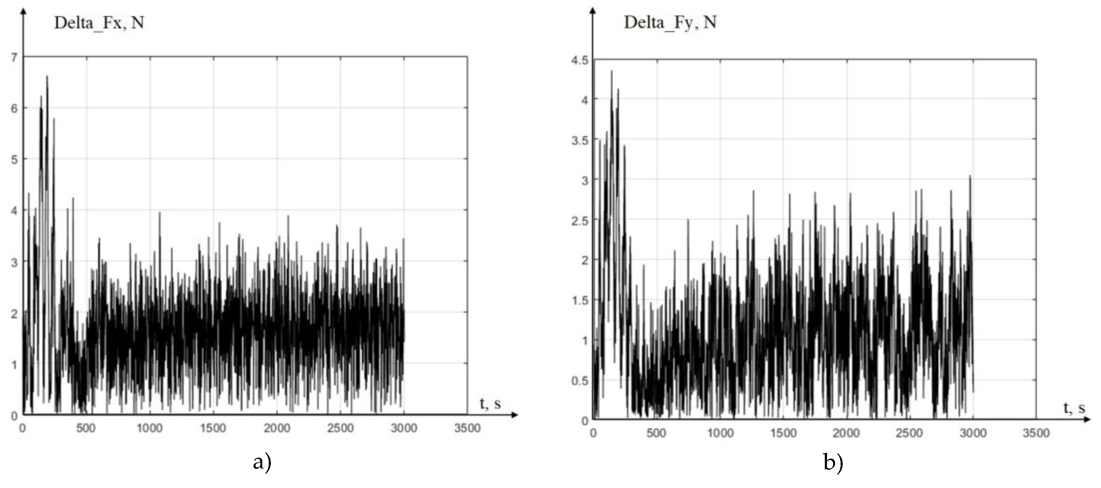
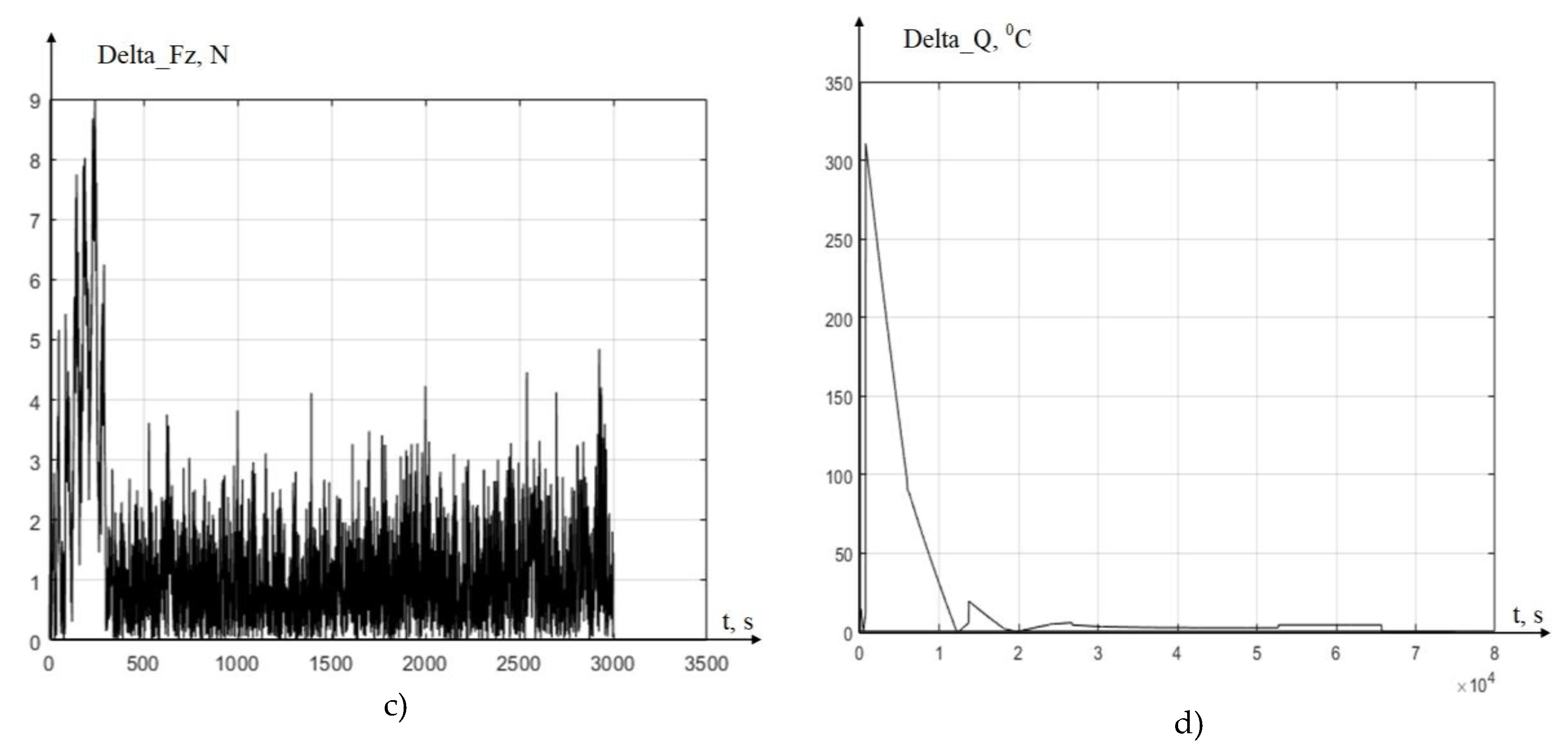
As can be seen from Figure 7, in the case under consideration, the experimental values of the cutting forces and temperature, which were established after cutting the tool into the part, increased compared to the previous case (see Figure 5). This growth is explained by the increase in the wear area of the cutting tool along the back edge. The corresponding model characteristics have also increased in the range of steady-state values, due to the fact that the wear value of the cutting wedge is included both in the calculated compounding forces and in the calculated temperature value, which is clearly visible in the system of equations (12). The greatest discrepancy in the dynamics of character change, as well as in the previous case, occurs in the area of the transition process. To quantify this discrepancy, consider the differences between the measured and calculated values (see Figure 8).
As can be seen from Figure 8, the values of dynamic mismatches have increased. The largest deviation in magnitude: delta_Fx=6.6 N, delta_Fy=4.4 N, delta_Fz=8.9 N, а delta_Q=310 0C. However, in the steady state, the misalignments decrease significantly, just as in the previous case.
4. Discussion
As it was already mentioned in the introduction, the task of synergetic analysis includes revealing the state space of the cutting process, which is represented through interaction in the coordinates of the state of this process, and determining the properties of the system. The task of synergetic synthesis is to determine such a set of control parameters available for change, the most important of which is the cutting temperature. The complexity of mathematical modeling, analysis and synthesis lies primarily in the fact that along the trajectory of the tool relative to the workpiece, the parameters of the mathematical model that reveals the interactions change. This is due to the fact that irreversible energy transformations take place in the cutting system, which irreversibly change the system parameters. The most obvious example of such changes is the irreversible development of a tool wear. Irreversible energy transformations, represented by the phase trajectory of the power of irreversible transformations in the work performed, are primarily reflected in the production of heat in various cutting zones. These are, first of all, the zones of primary and secondary plastic deformations, as well as the area of contact between the back face of the tool and the workpiece.
It should be noted that the currently existing ideas about the mathematical description of forces in state coordinates do not take into account the fact that irreversible energy transformations are primarily reflected in heat production. However, the temperature change directly affects the temperature deformations of the tool and the workpiece. To an even greater extent, they affect the parameters of the dynamic coupling formed by the cutting process, which are discussed in the previous paragraphs. They affect the final state of the system by changing the generated chip pressure on the front edge of the tool. They change the dependence of the friction forces on the relative sliding velocity. They contribute to the formation of various dissipative media in the contact zones of the tool faces and the cutting zone, etc. In this regard, the next natural stage in the formation of knowledge about the cutting system, the disclosure of which allows us to build a complete digital analogue of the processing process, is the stage of theoretical and experimental studies of the cutting process as an elastic-thermodynamic system. This approach was used in the work. Here, for the first time, a new elastic-thermodynamic view of the formation of virtual models of digital twins is proposed.
The studies presented in the Validation section have shown that the proposed mathematical model, reflecting the elastic-thermodynamic approach to describing the interaction processes during cutting, has a sufficiently high model adequacy. The main discrepancies between the simulated and measured signals are related to the vibration activity of the bearing systems of the 1K625 machine.
The main achievement in modeling the processes of thermodynamic interaction in the cutting system is the high predictive ability of the mathematical model. Indeed, if we do not take into account the transients during cutting, but rely on the steady-state values of forces and temperature, then in the digital twin system it is possible to predict these values with high accuracy. Based on this, it is possible to calculate in advance the effect of the selected modes on the cutting dynamics. In this regard, the obvious direction for further development of the proposed elastic-thermodynamic theory of cutting is to determine the optimal, from the point of view of dynamics, cutting modes on metal-cutting machines.
5. Conclusions
The paper reveals the main approaches to the synthesis of a mathematical description of the processes occurring during metal cutting on metal-cutting machines. This synthesis contains a new, previously unused approach to the description of the thermo-dynamics of the cutting process. The classical mathematical model of interactions during cutting is supplemented here by a description of the thermodynamic interaction, which is an integral part of the entire system of interactions arising during cutting. The thermodynamic interaction is represented as the sum of two temperature phenomena, the first of which is caused by the conversion of the power released in the cutting area into temperature, and the second is associated with the formation of a contact area on the back of the cutting tool, through which the heat released in this contact earlier is transferred to the future cutting area in one revolution before the current cutting. The mechanism of temperature transfer from the previous cutting stages to the current cutting zone identified here is called thermodynamic feedback, which significantly affects the interactions in the cutting system. For the first time, a proposed mathematical model describing the evolutionary nature of the formation of thermodynamic feedback of the cutting process makes it possible to link the thermodynamics of the cutting process with changes in the wear of the cutting tool.
In addition to the synthesis of the mathematical apparatus, a series of experiments was carried out on a 1K625 lathe, the results of which were used to compare experimental and simulated characteristics. A comparison of the results allows us to conclude that modeling the dynamics of the cutting process on metal-cutting machines is sufficiently adequate based on the proposed theory of elastic-thermodynamic interaction.
Author Contributions
Conceptualization, Lapshin V.P.; methodology, Lapshin V.P. software Khristorova V.V..; validation, Lapshin V.P..; formal analysis, Lapshin V.P..; investigation, Lapshin V.P..; resources, Turkin I.A..; data curation, Khristorova V.V.; writing—original draft preparation, Khristorova V.V.; writing—review and editing, Turkin I.A..; visualization, Turkin I.A.; supervision, Lapshin V.P..; project administration, Lapshin V.P..; funding acquisition, Lapshin V.P.. All authors have read and agreed to the published version of the manuscript.
Funding
The study was supported by the Russian Science Foundation, grant no. 24-29-00287. The work was carried out as part of the implementation of Agreement No. 075-03-2025-302/8 dated 29.10.2025 for the implementation of the research project “Development of software and hardware tools for monitoring and analyzing cutting parameters and operational characteristics of CNC machines” (FZNE-2025-0008).
Conflicts of Interest
The authors declare no conflicts of interest.
References
- Grieves M., Vickers J. Digital twin: Mitigating unpredictable, undesirable emergent behavior in complex systems //Transdisciplinary perspectives on complex systems: New findings and approaches. – 2017. – С. 85-113.
- Budak E. Machining process improvement through process twins //Proceedings of 3rd International Conference on the Industry 4.0 Model for Advanced Manufacturing: AMP 2018 3. – Springer International Publishing, 2018. – С. 164-179.
- Gouskov A. M. et al. Nonlinear dynamics of a machining system with two interdependent delays //Communications in Nonlinear Science and Numerical Simulation. 2002. Vol. 7. №. 4. pp. 207-221.
- Grabec I. Chaos generated by the cutting process // Physics Letter A. 1986. Vol. 117, N 8. P. 384 – 386.
- Zakorotny, V. L. Bifurcations of attracting sets of deformation displacements of a cutting tool during the evolution of the properties of the processing process / V. L. Zakorotny, V. E. Gwindzhilia // News of higher educational institutions. Applied nonlinear dynamics. 2018. – V. 26, № 5. – P. 20-38. [CrossRef]
- Budak E. Machining process improvement through process twins //Proceedings of 3rd International Conference on the Industry 4.0 Model for Advanced Manufacturing: AMP 2018 3. – Springer International Publishing, 2018. – С. 164-179.
- Kabaldin Yu. G., Shatagin D. A., Kuzmishina A.M. Development of a digital counterpart of a cutting tool for the machining industry // Trends in the development of science and education.2018. № 6. p.50-57. // URL: https://doicode.ru/doifile/lj/45/lj-12-2018-177.pdf.
- Chigirinsky, Yu. L. Technological aspects of digital machine-building production preparation / Yu. L. Chigirinsky, A. R. Ingemansson // High-tech technologies in mechanical engineering. – 2023. – № 9(147). – p. 39-48. [CrossRef]
- Lapshin V.P. et al. Development of a Conceptual Scheme for Controlling Tool Wear During Cutting, Based on the Interaction of Virtual Models of a Digital Twin and a Vibration Monitoring System //Sensors (Basel, Switzerland). – 2024. – Vol. 24. – №. 22. – p. 7403.
- Stépán G., Insperger T., Szalai R. Delay, parametric excitation, and the nonlinear dynamics of cutting processes //International Journal of Bifurcation and Chaos. 2005. Vol. 15. №. 09. pp. 2783-2798. [CrossRef]
- Moradi H. et al. Nonlinear behaviour of the regenerative chatter in turning process with a worn tool: Forced oscillation and stability analysis //Mechanism and Machine Theory. 2010. Vol. 45. №. 8. pp. 1050-1066. [CrossRef]
- Namachchivaya S. et al. Spindle speed variation for the suppression of regenerative chatter //Journal of Nonlinear Science. 2003. Vol.13. №. 3. pp. 265-288. [CrossRef]
- Longbottom J. M., Lanham J. D. Cutting temperature measurement while machining–a review //Aircraft Engineering and Aerospace Technology. – 2005.
- M’Saoubi R. et al. Thermal and microstructural analysis of orthogonal cutting of a low alloyed carbon steel using an infrared—charge-coupled device camera technique //Proceedings of the Institution of Mechanical Engineers, Part B: Journal of Engineering Manufacture. – 2002. – Т. 216. – №. 2. – С. 153-165.
- Spur G., Beyer H. Erfassung der temperaturverteilung am drehmeissel mit hilfe der fernsehthermographie //Ann. CIRP. – 1973. – Т. 22. – С. 3-4.
- Fnides B., Yallese M. A., Aouici H. Hard turning of hot work steel AISI H11: Evaluation of cutting pressures, resulting force and temperature //Mechanics. – 2008. – Т. 72. – №. 4. – С. 59-63.
- Kaminise A. K., Guimarães G., da Silva M. B. Development of a tool–work thermocouple calibration system with physical compensation to study the influence of tool-holder material on cutting temperature in machining //The International Journal of Advanced Manufacturing Technology. – 2014. – Т. 73. – №. 5. – С. 735-747.
- Reznikov A.N., Reznikov L.A. Thermal processes in technological systems. Moscow: Mechanical engineering, 1990.
- Zakorotny V. L., Gvindzhilia V. E. A synergetic approach to improving the efficiency of control of machining processes at metal-cutting mills //Metalworking: technology, equipment, tools. – 2021. – V. 23. – №. 3. – p. 84-99.
- Zakorotny V. L., Vinokurova I. A. The influence of heat production on the dynamics of the cutting process //Bulletin of the Don State Technical University.– 2017. – V. 17. – №. 3 (90).p -14-26.
- N. M. Belyaev, A. A. Raydno. Methods of the theory of thermal conductivity: Parts 1,2: Textbook. – Higher school, 1982. p 327.
- The influence of periodic fluctuations in the parameters of cutting modes on the temperature of the front surface of the turning tool / E. V. Fominov, V. E. Gvindzhilia, A. A. Marchenko, K. G. Shuchev // Advanced Engineering Research (Rostov-on-Don). – 2025. – V. 25, № 1. – p. 32-42. [CrossRef]
Figure 2.
Diagram showing the main aspects of thermodynamic interaction during cutting.
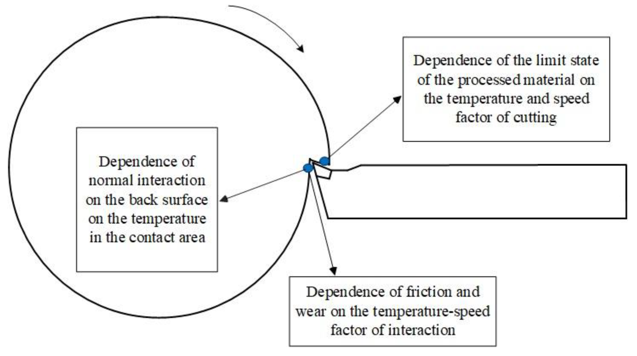
Figure 3.
Explanation of the forces and axes of deformation a) and a diagram explaining the elastic-dissipative model of deformation movements of the tool tip b).
Figure 3.
Explanation of the forces and axes of deformation a) and a diagram explaining the elastic-dissipative model of deformation movements of the tool tip b).
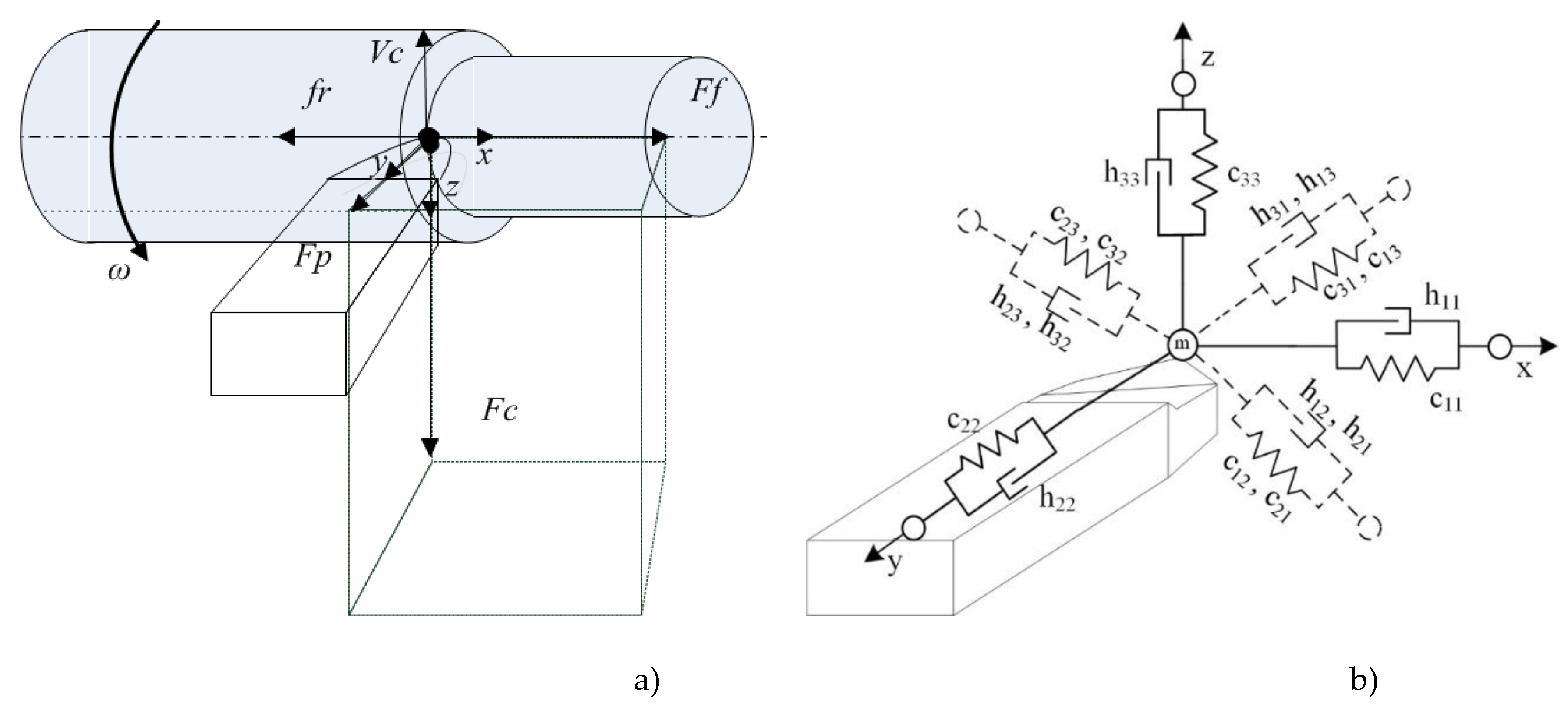
Figure 1.
Heat dissipation zone on the main back face of the tool a), and the formation of thermodynamic coupling through this zone b).
Figure 1.
Heat dissipation zone on the main back face of the tool a), and the formation of thermodynamic coupling through this zone b).
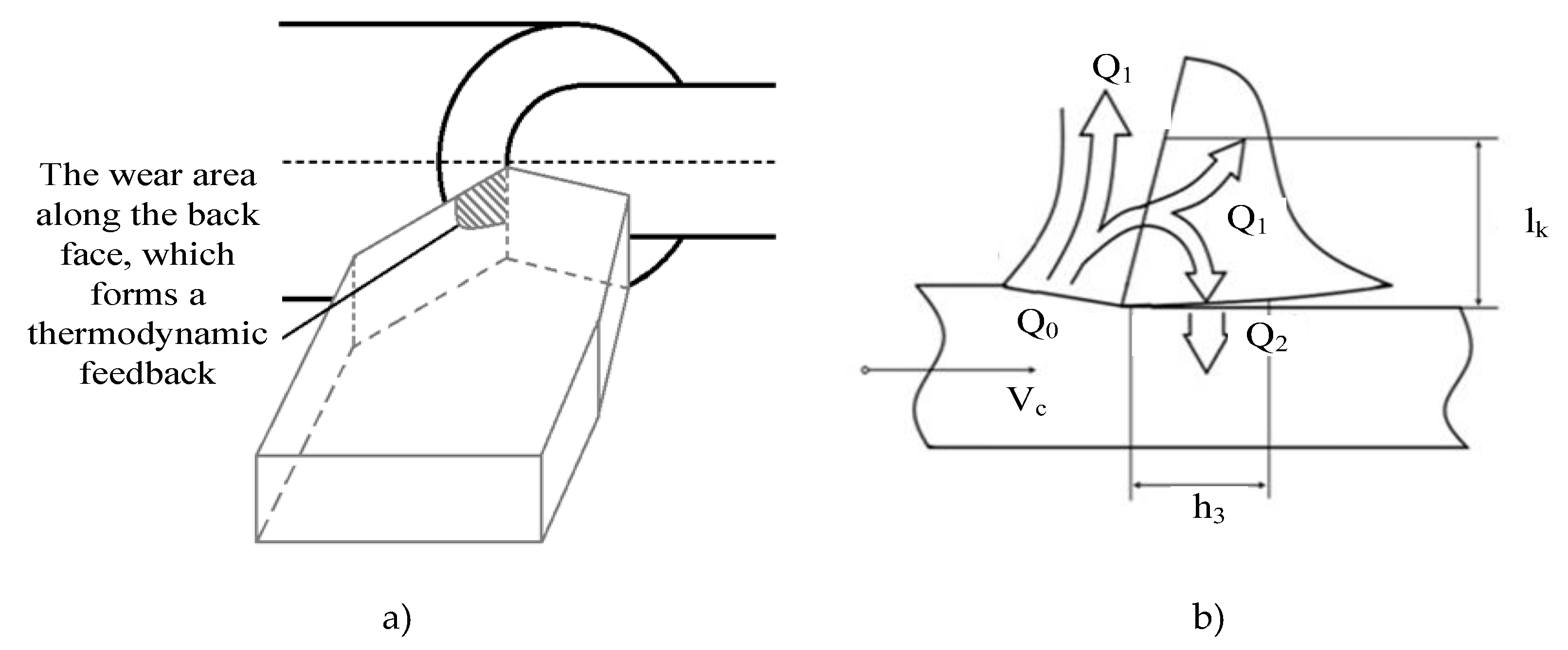
Figure 4.
Appearance of the experimental setup: a) 1K625 machine tool, b) measuring unit STD.201-1.
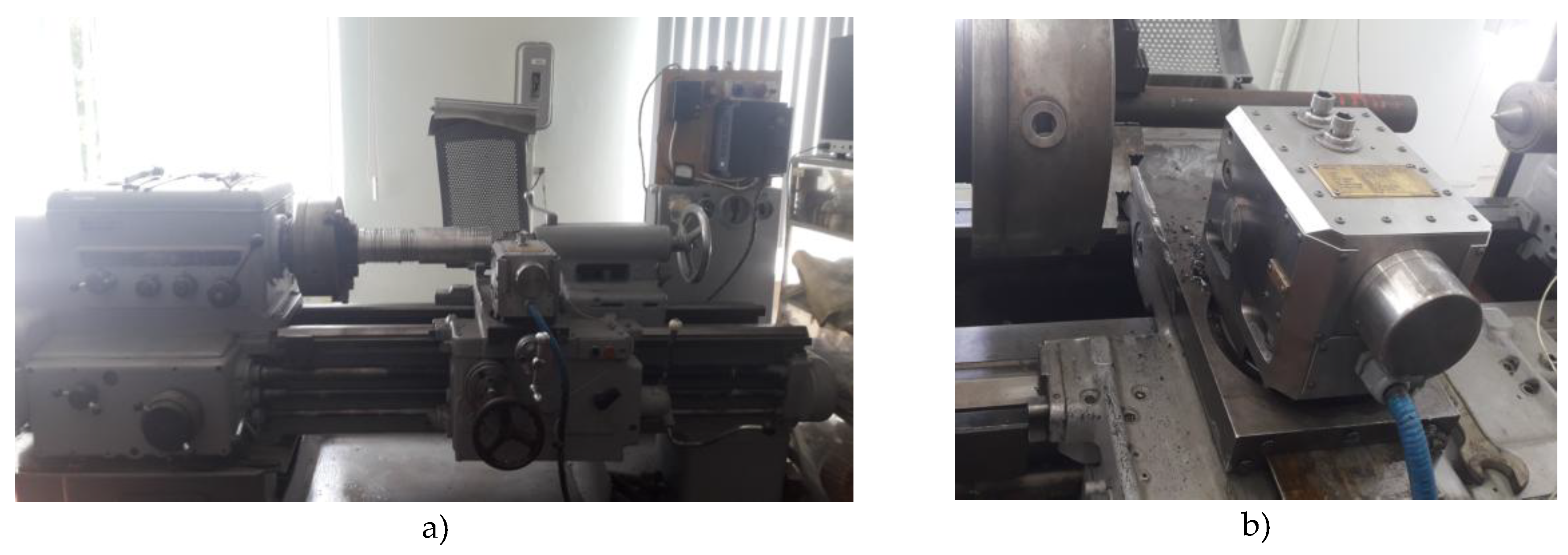
Figure 5.
The results of experimental measurements and modeling for h=0.15 mm: a) The component of power Fx, b) The component of power Fy, c) The component of power Fz: d) Temperatures in the cutting area.
Figure 5.
The results of experimental measurements and modeling for h=0.15 mm: a) The component of power Fx, b) The component of power Fy, c) The component of power Fz: d) Temperatures in the cutting area.
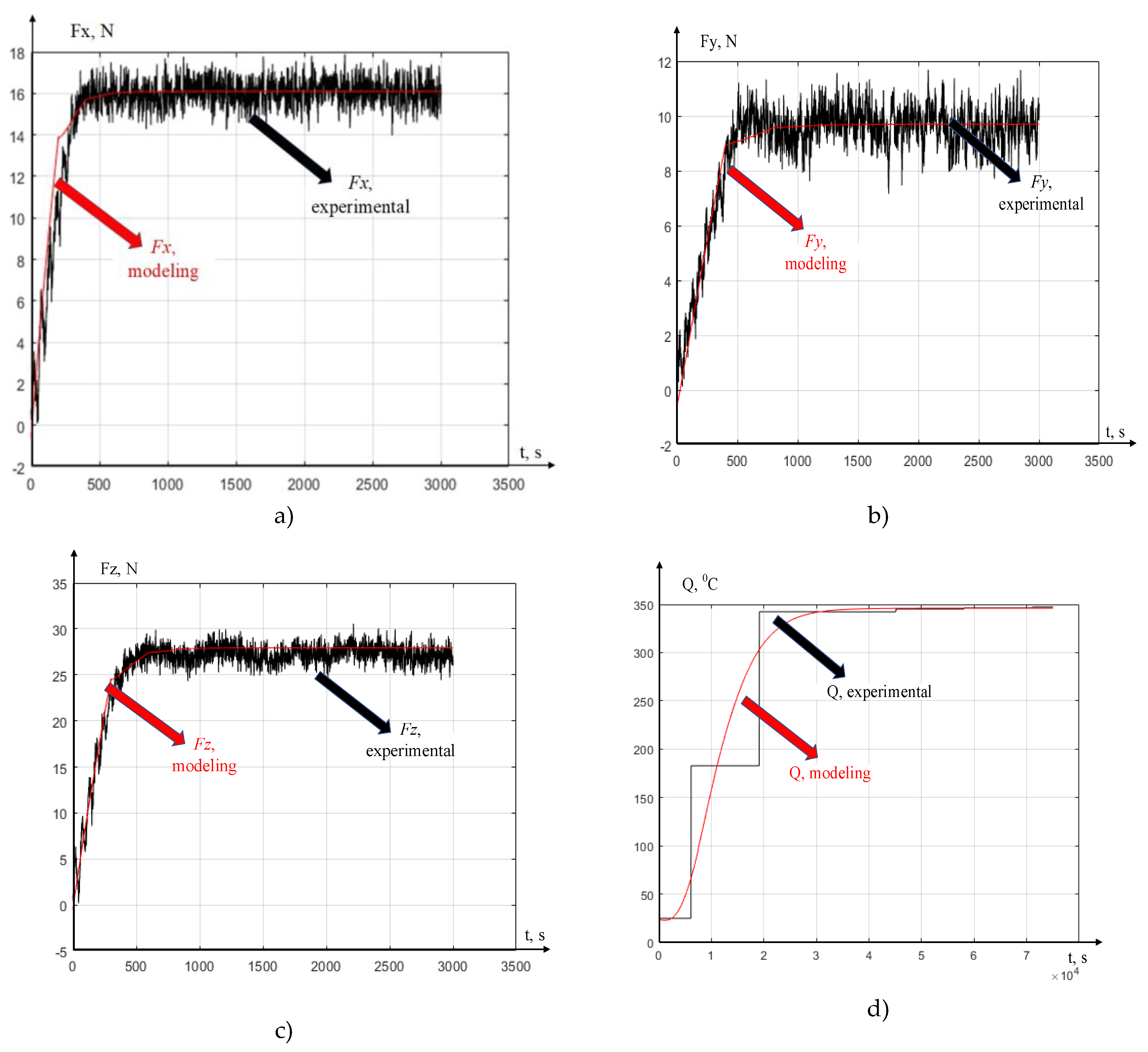
Figure 6.
Results of calculations of the difference between experimental and simulated characteristics: a) The component of power Fx, b) The component of power Fy, c) The component of power Fz: d) Temperatures in the cutting area.
Figure 6.
Results of calculations of the difference between experimental and simulated characteristics: a) The component of power Fx, b) The component of power Fy, c) The component of power Fz: d) Temperatures in the cutting area.
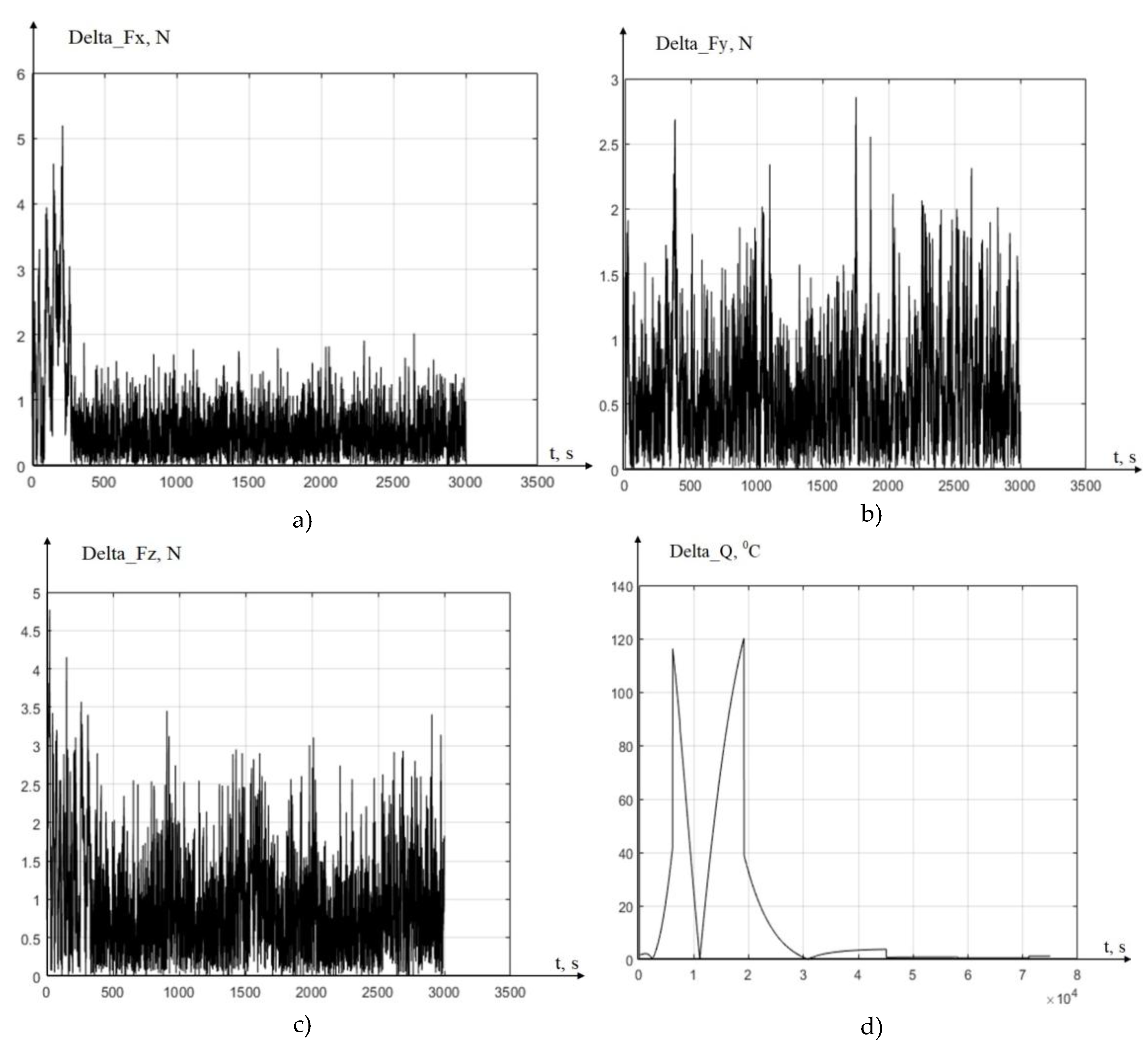
Figure 7.
The results of experimental measurements and modeling for h=0.27 mm: a) The component of power Fx, b) The component of power Fy, c) The component of power Fz: d) Temperatures in the cutting area.
Figure 7.
The results of experimental measurements and modeling for h=0.27 mm: a) The component of power Fx, b) The component of power Fy, c) The component of power Fz: d) Temperatures in the cutting area.
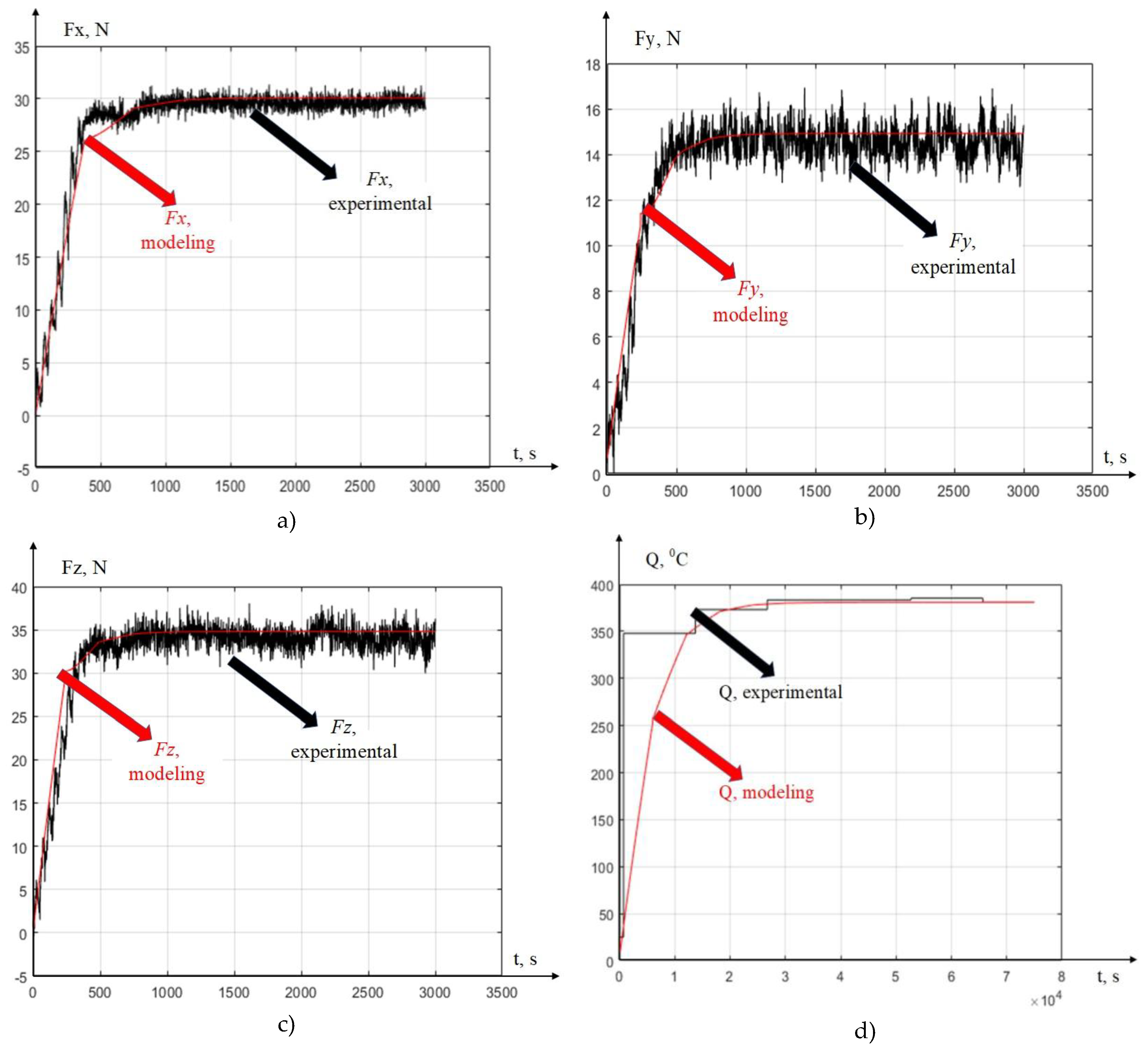
Figure 8.
The results of calculations of the difference between experimental and simulated characteristics for h=0.27 mm: a) The component of power Fx, b) The component of power Fy, c) The component of power Fz: d) Temperatures in the cutting area.
Figure 8.
The results of calculations of the difference between experimental and simulated characteristics for h=0.27 mm: a) The component of power Fx, b) The component of power Fy, c) The component of power Fz: d) Temperatures in the cutting area.
Disclaimer/Publisher’s Note: The statements, opinions and data contained in all publications are solely those of the individual author(s) and contributor(s) and not of MDPI and/or the editor(s). MDPI and/or the editor(s) disclaim responsibility for any injury to people or property resulting from any ideas, methods, instructions or products referred to in the content. |
© 2025 by the authors. Licensee MDPI, Basel, Switzerland. This article is an open access article distributed under the terms and conditions of the Creative Commons Attribution (CC BY) license (http://creativecommons.org/licenses/by/4.0/).
Copyright: This open access article is published under a Creative Commons CC BY 4.0 license, which permit the free download, distribution, and reuse, provided that the author and preprint are cited in any reuse.


