
Submitted:
15 August 2023
Posted:
17 August 2023
You are already at the latest version
Abstract
The article is devoted to the issues of assessing the impact of changes in the delay value in the feed direction, what determines the regenerative nature of self-excitation of the cutting system, on the dynamics of metal processing on metal-cutting machines. It is this interconnected model of the cutting system that allows to identify the main dynamic effects that occur in the cutting system, including the effect of vibrations regeneration when cutting along the track. The article also has a section dedicated to the experiment on a real metalworking machine, on which vibrations of the top of the cutting wedge of the tool were measured and based on these data, a real calculation of the delay time and the magnitude of the change in the area of the cut layer was carried out, due to variations in the real feed. The conducted studies have shown that in addition to the vibrations of the cutting tool in the direction of feeding, the vibration activity of the tool in the direction of cutting plays an essential role in ensuring the regenerative effect. The delay time constant of the operator is formed, which determines the real value of the feed during cutting.
Keywords:
cutting system
; cutting dynamics
; regenerative effect
; vibrations
1. Introduction
Since the middle of the 20th century, one of the main reasons for the loss of stability of cutting control systems has been the problem of the system self-excitation when cutting along the track, what has been called the regenerative effect [1-3]. In the Soviet scientific school of the 60s, this problem was also considered [4], however, it was considered not the main cause, but one of many possible ones. In the further development of scientific thought in this direction, the influence of the main nonlinearities on the dynamics of cutting processes, taking into account the regeneration of vibrations, was investigated [5-6]. It is worth noting here that these studies [1-3, 5-6] consider the scalar case of modeling a system of vibrational movements of the tool tip. The modern understanding of the causes of cutting control systems self-excitation on metal-cutting machines is largely based on the research of previous authors, however, the models used in this case are somewhat more complicated, so in [7], a variant of the model of the cutting system dynamics with two degrees of freedom is considered. In [8], the effect of vibration regeneration on the milling process is considered, but the model is scalar in nature. In [9], a scalar model for the case of orthogonal cutting is also presented; here the author reveals the formation of periodic, quasi-periodic and chaotic movements of the tool tip, the transition to which is caused by a regenerative effect. In [10], the author's method of suppressing vibrations during cutting caused by the regenerative effect is presented. An interesting work in this field is [11] an article in the list of sources, which discusses the simulation of vibration regeneration during turning, through a partial differential deformation model. Of interest is also the work [12], where the authors developed bifurcation diagrams defining the relationship between the applied processing parameters and the amplitude of the resulting limit cycles. One of the most famous modern researchers on the issue of the cutting process dynamics, as well as the effect on it of the regeneration of vibrations when cutting along the track, is Stépán G [13], whose work examines the effect of the delay constant on the nonlinear dynamics of the cutting process. In addition to theoretical research in the field of regeneration of tool tip vibrations during cutting, a fairly large number of practically oriented works in this area are known. Thus, in [14], the development and implementation of a subsystem for regulating the cutting speed in Numerically Controlled (CNC) machines is considered, wha allows avoiding cutting modes that cause of the subsystem self-excitation of deformational tool movements. A similar work [15], in which the issue of optimizing the cutting system according to the criterion of minimizing the vibrations of the tool tip is considered. In the works [16-18], methods of analytical prediction of vibration regeneration are considered, the use of which in cutting control systems will eliminate the variants of stability loss in the subsystem of deformation movements.
One of the factors uniting all these works [1-18] is the presence in the mathematical model of a time constant that characterizes “time delay" signals in this model. The issues of stability assessment for models of systems with a delay are a separate, extremely interesting, mathematical problem [19]. However, in all these cases, the time delay was introduced into the mathematical model as a simulation parameter. In the case of a real metalworking process on metal-cutting machines, such a time delay depends on the rate of change in the coordinates of the system state of deformation movements of the tool tip. Mathematical models that take into account such a dependence of the delay value on the speed coordinates of the cutting process state do not exist today.
Of interest are works in which mathematical models of dynamics were considered in variations relative to a constant equilibrium point considered in a moving coordinate system, the movement of which is determined by the trajectories of the machine's executive elements [20-21]. The trajectories of the machine's actuating elements are considered during longitudinal turning with constant values of the workpiece revolution speeds and longitudinal feeding at zero speed of the transverse caliper. Therefore, when considering the regenerative effect, it is assumed that the value of the lagging argument is constant. When forming the feed, two arrays of trajectories are considered, which are shifted relative to each other in time by a constant value of the lagging argument. As a result, the effects of synchronization, asynchronous interactions, as well as the effects of complex formation, attracting sets of feeds and corresponding cutting forces are observed, which can lead to the formation of chaotic attractors of deformations [22-25]. In addition to the regeneration of vibrations during cutting, the dynamics of deformation movements of the tool tip is also significantly affected by the process of temperature formation in the contact zone of the tool and the workpiece, which includes the conversion of irreversible transformations power into heat generated during cutting [26].
The declared approaches to the formation of mathematical models of cutting control systems [20-26] are largely based on the representation of forces that hinder the formative movements of the tool in the coordinates of deformations of the tool tip. With this representation, the lag constant, in the real cutting process determined by the spindle revolution speed and the deformation mixing of the tool tire in the cutting direction, should also be represented in the same coordinates. In fact, the delay constant “time delay” is determined by the speed of revolution and the rate of deformation displacements of the tool tip in the direction of revolution. Taking into account this previously unexplored fact significantly changes the model of the cutting system, which can no longer be scalar.
All this forms the purpose of the study, which consists in assessing the dynamics of the cutting system according to a mathematical model with a lagging argument, the value of which depends on the coordinates of the state of the system. The cutting forces in this case should include a subsystem of the force reaction formed on the back faces of the cutting wedge of the tool [27-28], which allows taking into account the power of irreversible transformations allocated at this contact [26]. In addition, the influence of the sets of deformation displacements formed in the phase space, which affect the super-low-frequency reactions of the cutting system, is subject to research.
Summarizing the above and using the terminology of automatic control theory, we note that deformations in the directions of longitudinal and transverse feeds cause the decrease in the area of the cut layer, that is, they form a negative feedback. Deformations in the direction of the cutting speed lead to flexible positive feedback, which cannot but affect the properties of the dynamic cutting system. This joint is flexible because it changes forces depending on the strain rate. This also changes the lag argument. The disclosure of this connection affecting the properties of the cutting system, discussed in the article, complements the knowledge about it, which determines the scientific novelty and significance of the studies listed below.
2. Development of a basic mathematical model
To clarify the mathematical model, we will consider the main axes of the cutting tool deformation, as well as the orientation of the force reaction to the shaping movements of the tool, which are shown in Figure 1.
Taking into account the scheme of the force reaction decomposition from the cutting process to the shaping movements of the tool presented in Figure 1, the forces decomposed along the axes of deformation can be represented as follows [29,30]:
where χ1,χ2,χ3 are the coefficients of decomposition of the cutting force F on the axis of deformation of the tool. The Fc component has the greatest value here, which most accurately reflects the cutting force itself and determines the vibration activity of the tool in the direction of z axis. The force itself, which prevents the shaping movements of the tool, can be represented as the product of the cut layer area by some indicator characterizing the chip pressure on the front face of the cutting wedge of the tool, as it is presented in the expression below [20-25]:
where ρ is the constant determining the value of the specific chip pressure, per millimeter of the area of the layer cut during cutting, tp is the depth of the cut layer (mm), S is the feed per revolution (mm).
It should be noted here that the actual cutting depth and the actual feed per revolution will depend on the vibration values of the tool tip, in the case of cutting depth, it will be determined as follows (see Figure 1):
where y is the amount of deformation of the tool tip in the radial direction.
As for the amount of feed per revolution, it will be determined as the solution of the following integral [20-25]:
where Vf is the speed in the feed direction, T is the lag time constant calculated as the revolution time of the spindle with the part fixed in it, dx/dt is the speed of vibrations of the cutting tool tip in the feed direction.
In expression (5), T – time delay depends on the magnitude of the oscillations of the cutting wedge tip in the direction of z axis (see Figure 1). Let's illustrate this explanation with the following figure (see Figure 2).
In Figure 2, two variants of the growth of the cutting path are considered, the red color indicates the option when cutting is carried out at the speed of Vc = 2100 mm /sec and without taking into account the vibrations of the cutting wedge in the direction of z axis, and in black the same variant of the cutting path, but with vibrations superimposed on it in the direction of z axis. For the convenience of reasoning, we assumed that the diameter of the processed product (workpiece) is assumed to be 32 mm, which gives approximately 100 mm of path per revolution of the spindle. As can be seen from the presented figure, under the conditions of vibration activity of the cutting wedge, the actual cutting period (the delay value in equation (5)) differs significantly from the value determined by the cutting program.
Based on these considerations, the real feed defined by expression (5) will differ from the given feed, and this difference will consist not only in the two last terms of the sum, but also the first term of this sum will differ due to the variation of the time constant T (see Figure 2).
Thus, the regenerative effect during cutting will be determined not only by the ratio of the trace during cutting and the current vibrations of the tool in the feed direction, as well as the vibrations of the cutting wedge in the cutting direction. All this together creates a complex system of related vibration activity of the cutting tool, which will determine the vibration levels during cutting.
3. Description of the experiment and data processing methodology
To determine the feed value during cutting, based on our previous reasoning, it will be necessary to evaluate the vibrational activity of the tool tip, both in the feed direction (along the x axis) and in the cutting direction (along the z axis). Thus, the vibration activity registration system should include two vibration transducers mounted on the corresponding axes of the instrument. To solve this problem, we have developed a measuring system that includes two vibration measurement sensors. The upgraded 1K625 universal lathe, shown in Figure 3 (a), was used as a test bench (the possibility of smoothly changing the cutting speed). The parameters of the mode in the experiments were as follows: feed 0.11 mm/rev, cutting depth tp0 = 1 mm. Over the entire period of the experiment, these cutting parameters remained unchanged. The cutting speed varied in increments of 167 millimeters per second (10 meters per minute) from a value of 1167 millimeters per second (70 meters per minute) to a value of 2833 millimeters per second (170 meters per minute). As a tool, we used the holder MR TNR 2525 M22 and a pentahedral plate 10113-110408 T15K6 as a cutter on it (see Figure 3 b)), with the angle in the upper part (angle of attack) 350, and the main angle in the plan 800 (the angle between the projection of the main cutting edge on the main plane and the feed direction), both the holder and the plate are manufactured in Russia. In the experiment, a shaft made of steel grade 45 (GOST) was processed, this steel grade is widely used both in Russia (GOST 2591-2006 - Steel 45 (st45) - high-quality structural carbon), and in the USA and Germany, the American standard ASTM A568M marks this type of steel as AISI 1045, and in Germany's DIN17200 standard is Ck45. Steel 45 (st45) contains: from 0.42 to 0.5% carbon (this can be traced in the name of the steel grade), 97% iron, as well as percentages of silicon, manganese, nickel, sulfur, phosphorus, chromium, copper, arsenic [31-33]. The shaft made of grade 45 steel was made using hot rolling technology, before the experiment the shaft was cut to a length of 75 centimeters, then a preliminary finishing treatment of the shaft surface and precise alignment was carried out. The choice of this steel grade is associated with its wide use in mechanical engineering, which is due to the high quality of structural steel and its relatively low price in the steel market.
In the measurement system shown in the figure, two sensors (vibration transducers) manufactured by GLOBAL TEST (manufacturing country Russia) AP2098-500 and connected to the amplifier converter of GLOBAL TEST AR13, which converts the current signal into voltage and amplifies it. These vibration converters have an analog output with a signal having a very high natural cutoff frequency of 48 kHz, the cutting process itself has a base vibration frequency in the range from 1 to 4 kHz. To digitize such a signal, it is necessary to have a quantization frequency of at least 8 kHz, in this regard, an ADC of the company L-CARD (manufacturer country Russia) E14-440 AD/DA CONVERTER with a USB 2.0 cable (USB Type B) was used. In the measurement system shown in the figures, which uses two sensors (vibration transducers) to create a GLOBAL TEST (the country of origin is Russia) AP2098-500 and connected to a stable converter for the GLOBAL TEST AR13, which converts the current signal into voltage and sees it. These vibration converters have an analog output with a signal having a very high natural cutoff frequency of 48 kHz, the cutting process itself has a base vibration frequency in the range from 1 to 4 kHz. To digitize such a signal, it is necessary to have a quantization frequency of at least 8 kHz, in this regard, an ADC of the company l-card (manufacturer country Russia) E14-440 AC /CA converter with a cable and USB 2.0 (USB Type B) was used.
The interface of the ADC program is a dialog box in which we can determine the duration of data recording and set the quantization frequency of the signal taken from the sensors. An example of the ADC interface is shown in Figure 4.
As can be seen from Figure 4, the program interface allows us to see the vibration acceleration of the tool tip in the appropriate direction. The program also outputs an array of stored vibration acceleration data in the form of two vectors, a vector of vibration acceleration values and a vector of discreet numbers. Since we used the value of the quantization frequency of the signal at 10 kHz, 10,000 values are represented in every vector for every second of measurements. Such a high quantization frequency is due to the fact that the main events associated with vibrations taken from the instrument occur in the frequency range from 1 kHz to 5 kHz. According to the requirements of the Nyquist—Shannon theorem, to restore such a signal from a discrete value, a quantization frequency of at least twice the natural frequency of the original analog signal is required.
The values of vibration accelerations obtained in the experiments were processed by us in the Matlab mathematical modeling environment, where programs were written that allow double integration of vibration accelerations with filtering of the average value, calculated here by the moving average method. In addition, programs were compiled for calculating the RMS value of vibration accelerations (MCP) at the measurement sites, as well as a program for spectral analysis of the received signals. The results of preprocessing one of the measured signals are shown in Figure 5.
As can be seen from Figure 5, the integration technique we have adopted as a whole adequately converts the vibration acceleration signal into a vibration velocity and vibration displacement signal in the direction of z axis. However, to verify the correctness of the obtained solution, at every step of the experiment we carried out a comparative analysis of the signal spectra shown in Figure 5. The results of such a comparison are presented in Figure 6, in the form of power spectra of vibration acceleration signals, vibration velocity and vibration displacement of the tool tip in the direction of z axis.
As can be seen from Figure 6, in all considered cases of the signal under study, there is a surge in vibration power at the frequency from 2000 to 3000 Hz, however, as integration increases, the role of vibrations at low frequencies increases, which is explained by the inertia of the instrument, which does not have time to respond to the high-frequency harmonics of the vibration acceleration signal.
Thus, we conducted twelve experiments with different cutting speeds, the data on which we processed in our own development programs.
4. Results and discussion
It is convenient to present the data obtained as a result of a series of experiments for further analysis in the form of MCP values (RMS values), which were calculated according to the following formula:
where VA is the power of the vibration signal for the observation period Ti, which, for convenience, we received in one second. It is convenient to present the results of signal processing in the form of a table (see Table 1).
As can be seen from Table 1, along with the increase in the cutting speed, the power of the measured vibration signal also increases, but after reaching a speed of 140 meters per minute (2333 millimeters per second), the total vibration power is stabilized, due to the decrease in the power of the vibration signal in the direction of z axis. The increase in vibration power with the increase in cutting speed is associated with the general vibration pattern of processing on an experimental machine, that is, the power increases due to the increase in vibrations of the spindle group, as well as all moving parts of the machine. The drop in vibration power in the direction of z axis is explained by the stabilization of the cutting force, which should be associated precisely with the regenerative effect, which in turn can be explained by the effect of stabilization of the value of the actual feed in the direction of x axis (see expressions 4-5). To increase the visibility of reducing the vibration power of the cutting tool, at cutting speeds of 150 and 160 meters per minute, we present the dependence of the vibration acceleration along z channel in the form of the graph (see Figure 7).
As can be seen from Figure 7, the MCP curve has at least two local minima, each of which can be caused by the influence of the stability lobe of the regenerative effect. To clarify this hypothesis, we need to conduct a more detailed analysis of the data in order to determine the values of the actual feed (see expression 5). The results of calculating the time constant and the real feed value associated with it, for cases of cutting at the speed of 160 meters per minute, which corresponds to the minimum of the vibration acceleration MCP removed from the tool in the direction of z axis, are shown in Figure 8.
As can be seen from Figure 8, the value of the actual feed fluctuates significantly in the vicinity of the set value, we observe similar fluctuations in the calculated value of the delay time constant. For a more adequate analysis of the actual value of the feed, we will consider the calculated value of the vibration power of this value, for the calculation of which we somewhat transform expression (6), removing the value of the average component of the feed in it:
where is a given constant value of the feed quantity.
The results of the calculation of the vibration power indicator of the actual feed value are presented in Table 2.
The analysis of the data presented in Table 2 shows that at cutting speeds of 150-160 meters per minute, a stabilization of the characteristic is observed, which indirectly confirms our hypothesis about the decrease in the influence of tool vibrations in the direction of giving. This decrease is due to the formation of such a real revolution period, in which the values of the current and lagging by the amount of delay, vibration displacement compensate for each other. In other words, with some variation of the time delay, in expression (5), the vibrations of the real feed are smoothed out.
To visualize the dependence of the actual feed value oscillation on the cutting speed, consider the graphical interpretation of the data given in Table 2 (see Figure 9).
As can be seen from Figure 9, the vibration power of the actual feed value actually has a declared local minimum in the vicinity of the same cutting speed value as in Figure 7. In other words, the area of stabilization of the cutting force in the direction of z axis is due to the stabilization zone of the actual feed value.
Thus, the conducted studies have shown that in addition to the vibration activity of the cutting tool in the feed direction, the regenerative effect depends on the vibration activity of the tool in the cutting direction, which affects the real value of the delay when cutting along the track.
5. Conclusion
The conducted studies have shown that in addition to the vibrations of the cutting tool in the direction of feeding, the vibration activity of the tool in the direction of cutting plays an essential role in ensuring the regenerative effect. The delay time constant of the operator is formed, which determines the real value of the feed during cutting. The novelty of the research is that deformations in the direction of the cutting speed lead to the formation of a flexible positive feedback, which subsequently affects the dynamics of the cutting system. Since this direction of tool deformations does not participate in the formation of the cut layer area and, as a consequence, in the formation of the cutting force, the effect of these fluctuations on the dynamics of the cutting system becomes unobvious. However, by changing the delay argument depending on the magnitude of these vibrations, the connection between the cutting force and the dynamics of the cutting process with the vibrations of the cutting tool in the cutting direction is revealed. It should be noted that the disclosure of this non-obvious connection affecting the properties of the cutting system complements modern ideas about the interconnectedness of the system of deformation movements of the tool and the force reaction from the cutting process to the shaping movements of the tool, which determines the scientific novelty and significance of our research.
Conflicts of Interest
The authors declare no conflict of interest.
References
- Hahn, R.S. On the theory of regenerative chatter in precision grinding operation. Transactions of American Society of Mechanical Engineers. 1954, 76, 356. [Google Scholar] [CrossRef]
- Tobias, S.A.; Fishwick, W. Theory of regenerative machine tool chatter. The Engineer. 1958, 205, 199–203. [Google Scholar]
- Merrit, H.E. Theory of self-excited machine-tool chatter-contribution to machine tool chatter research. ASME Journal of Engineering 1995, 447–454. [Google Scholar] [CrossRef]
- Kudinov V.A. Dinamika stankov [Dynamics of machine tools]. M.: Mechanical Engineering, Russia, 1967, P.359 (In Russ.).
- Tlusty J., Z. Masood. Chipping and breakage of carbide tools. 1978, 403–412. [Google Scholar]
- Tlusty, J.; Ismai, F. Basic non-linearity in machining chatter. Ann. CIRP. 1981, 299–304. [Google Scholar] [CrossRef]
- B.A.G. Yuvaraju, J. Srinivas, B.K. Nanda Nonlinear dynamics of friction-induced regenerative chatter in internal turning with process damping forces. Journal of Sound and Vibration. 2023, 544, 117386. [CrossRef]
- Gouskov, A. M., Voronov, S. A., Paris, H. & Batzer, S. A. Nonlinear dynamics of a machining system with two interdependent delays. Commun. Nonlin. Sci. Numer. Simul. 2002, 7, 207–221.
- Litak, G. Chaotic vibrations in a regenerative cutting process. Chaos Solit. Fract. 2002, 13, 1531–1535. [Google Scholar] [CrossRef]
- Namachchivaya N., S., Beddini R. Spindle speed variation for the suppression of regenerative chatter. J. Nonlin. Sci. 2003, 13, 265–288. [CrossRef]
- Wahi, P., Chatterjee A. Self-interrupted regenerative metal cutting in turning. J. Non-Lin. Mech. 2008, 43, 111–123. [CrossRef]
- Mohammadi, Y., Ahmadi K. Finite-amplitude stability in regenerative chatter: The effect of process damping nonlinearity and intermittent cutting in turning. Journal of Sound and Vibration. 2022, 537, 117158. [CrossRef]
- Stépán, G., Insperger T., Szalai R. Delay, parametric excitation, and the nonlinear dynamics of cutting processes. International Journal of Bifurcation and Chaos, 2005, 15, 2783–2798. [CrossRef]
- Haifeng Ma, Jianhua Wu, Liuqing Yang, Zhenhua Xiong Active chatter suppression with displacement-only measurement in turning process. Journal of Sound and Vibration. 2017, 401, 255–267. [CrossRef]
- Reith M.J., Bachrathy D., Stepan G. Improving the stability of multi-cutter turning with detuned dynamics. Machining Science and Technology. 2016, 20, 440–459. [CrossRef]
- Altitias, Y., Budak E. Analytical prediction of stability lobes in milling. CIRP Annals - Manufacturing Technology, 1995, 44, 357–362. [CrossRef]
- Altitias Y., M.Weck. Chatter stability of metal cutting and grinding. CIRP Annals – Manufacturing Technology. 2004, 53, 619–642. [CrossRef]
- Altitias, Y. Analytical prediction of three dimensional chatter stability in milling. JSME International Journal, Seri C: Mechanical Systems, Machine Elements and Manufacturing, 2001, 44, 717–723. [Google Scholar] [CrossRef]
- Insperger, T, Stepan, G, Semi-discretization method for delayed systems. International Journal for Numerical Methods in Engineering, 2002, 55, 503–518. [CrossRef]
- Zakovorotny, V. Вifurcations in the dynamic system of the mechanic processing in metal-cutting tools. WSEAS Transactions on Applied and Theoretical Mechanics. 2015, 10, 102–116. [Google Scholar]
- Zakovorotny, V.L., Lukyanov A.D., Gubanova A.A., Khristoforova V.V. Bifurcation of stationary manifolds formed in the neighborhood of the equilibrium in a dynamic system of cutting. Journal of Sound and Vibration. 2016, 36, 174–190. [CrossRef]
- Zakovorotnyi V.L., Gubanova A.A., Lukyanov A.D. Аttractive manifolds in end milling. Russian engineering research. 2017, 37, 158–163. [CrossRef]
- Zakovorotnyi V.L., Bykador V.S. Сutting-system dynamics. Russian Engineering Research. 2016, 36, 591–598. [CrossRef]
- Zakovorotny, V.L., Gvindjiliya V.E. The properties of attracting sets of tool deformation displacements in the trajectories of the shape-generating movements in turning. Proceedings of Higher Educational Institutions Маchine Building. 2022, 3, 15–30. [CrossRef]
- Zakovorotny, V.L., Gvindjiliya V.E. Self-organization and evolution in dynamic friction systems. Journal of Vibroengineering. 2021, 23, 1418–1432. [CrossRef]
- Lapshin, V. P. Turning tool wear estimation based on the calculated parameter values of the thermodynamic subsystem of the cutting system. Materials 2021, 14, 6492. [Google Scholar] [CrossRef] [PubMed]
- Rusinek, R., Wiercigroch, M., Wahi, P. Influence of Tool Flank Forces on Complex Dynamics of Cutting Process. International Journal of Bifurcation and Chaos, 2014, 24, 1450115. [CrossRef]
- Rusinek R., Wiercigroch M., Wahi, P. Modelling of frictional chatter in metal cutting. International Journal of Mechanical Sciences. 2014, 89, 167–176. [CrossRef]
- Lapshin V., P. Vliyanie skorosti rezaniya metallov na regeneraciyu vibracionnyh kolebanij instrumenta v stankah tokarnoj gruppy [The effect of metal cutting speed on the regeneration of tool vibration vibrations in turning group machines]. Metal Working and Material Science. 2020, 22, 65–79, (In Russ.). [Google Scholar] [CrossRef]
- Lapshin V., P. Modeling of the influence of the wear of the cutting wedge of the tool on the stability of the metal turning process. Journal of Vibroengineering. 2022, 24, 1378–1395. [Google Scholar] [CrossRef]
- Metal products from nonalloyed structural quality and special steels. General specification. https://docs.cntd.
- American standard ASTM A568M. https://www.astm.
- DIN Standards. https://www.din.
Figure 1.
Diagram of deformation vibrations and orientation of forces.
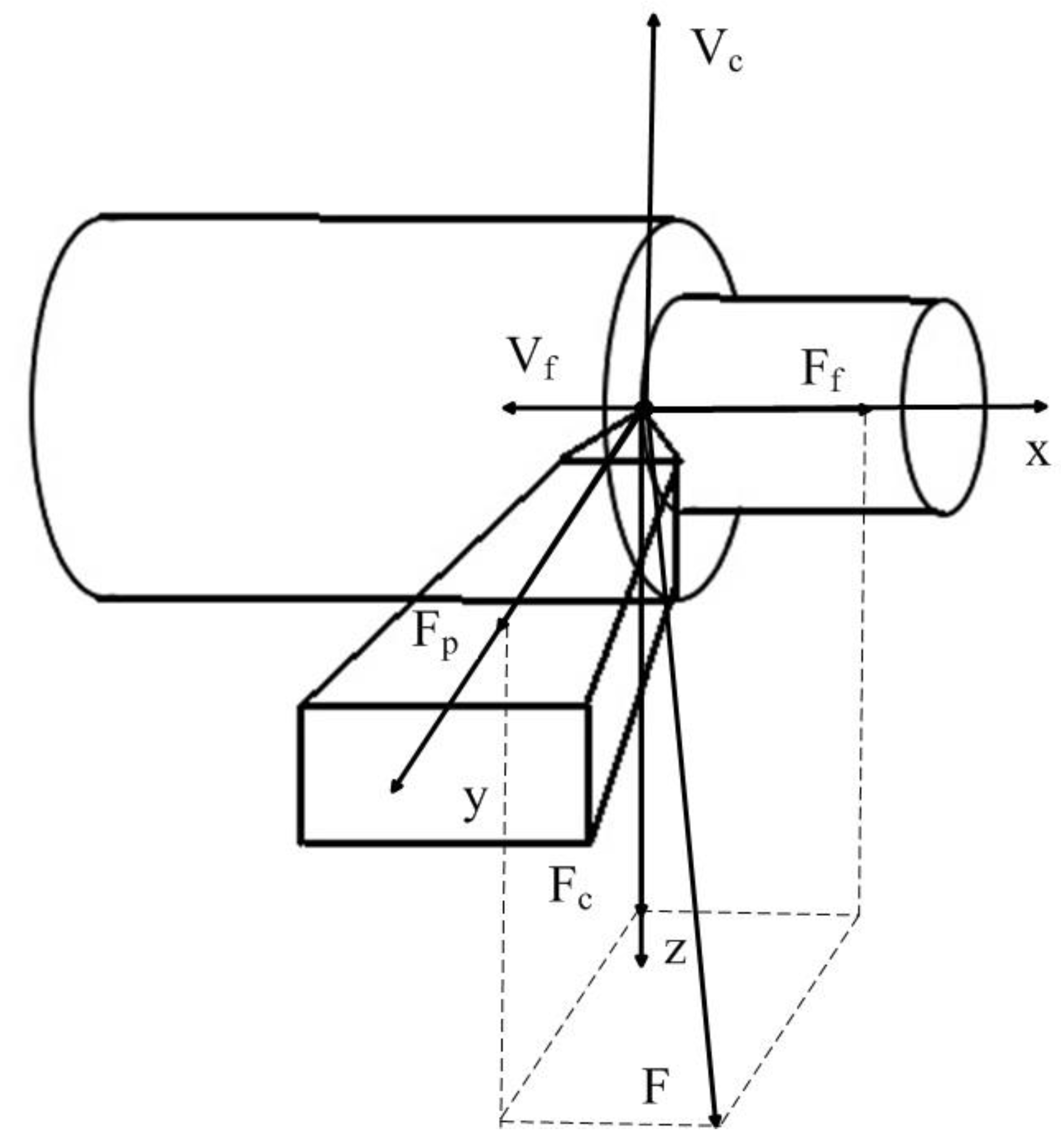
Figure 2.
Example of the delay period variation during cutting.
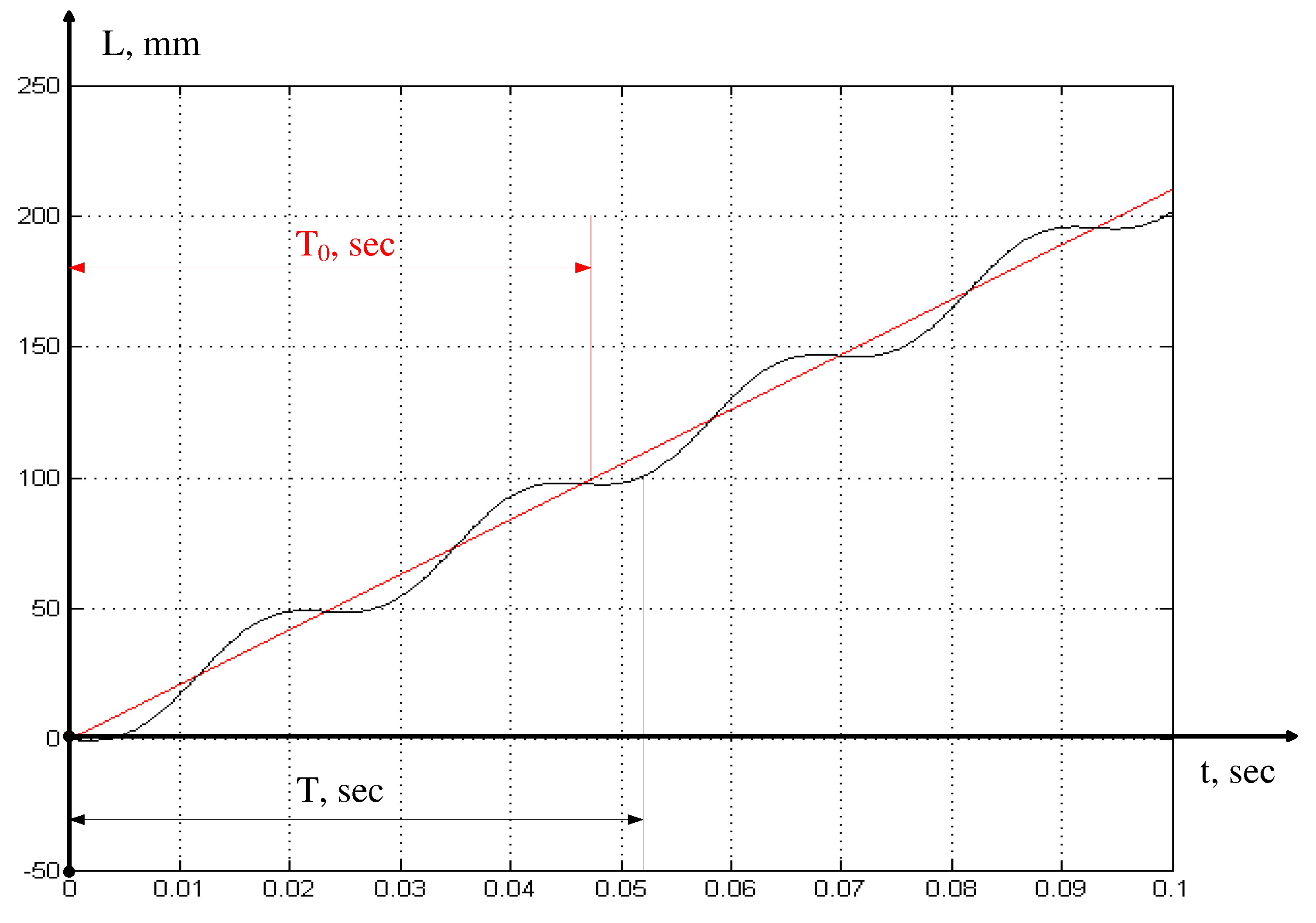
Figure 3.
Measuring system a) upgraded 1K625 machine, b) tool, c) tool with vibration converters AP2098-500, d) vibration converter AP2098-500, e) ADC and signal amplifier with vibration converter, f) measuring system on the machine.
Figure 3.
Measuring system a) upgraded 1K625 machine, b) tool, c) tool with vibration converters AP2098-500, d) vibration converter AP2098-500, e) ADC and signal amplifier with vibration converter, f) measuring system on the machine.
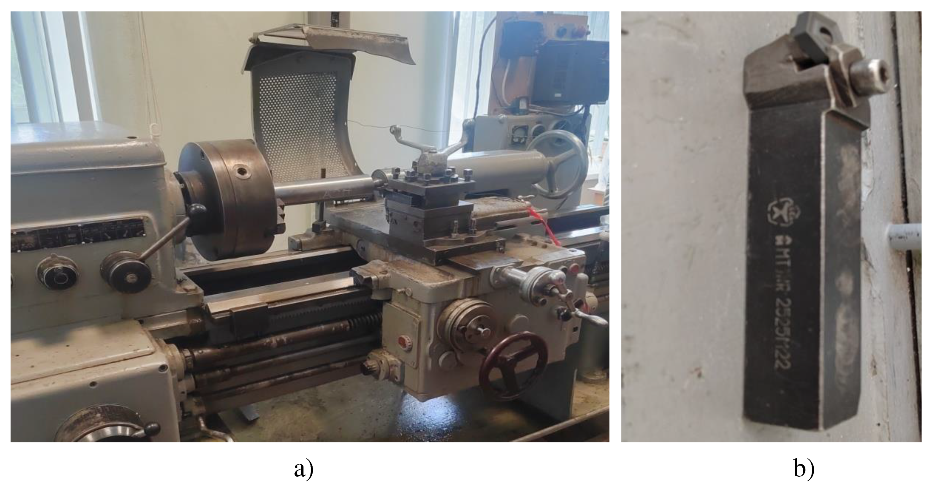
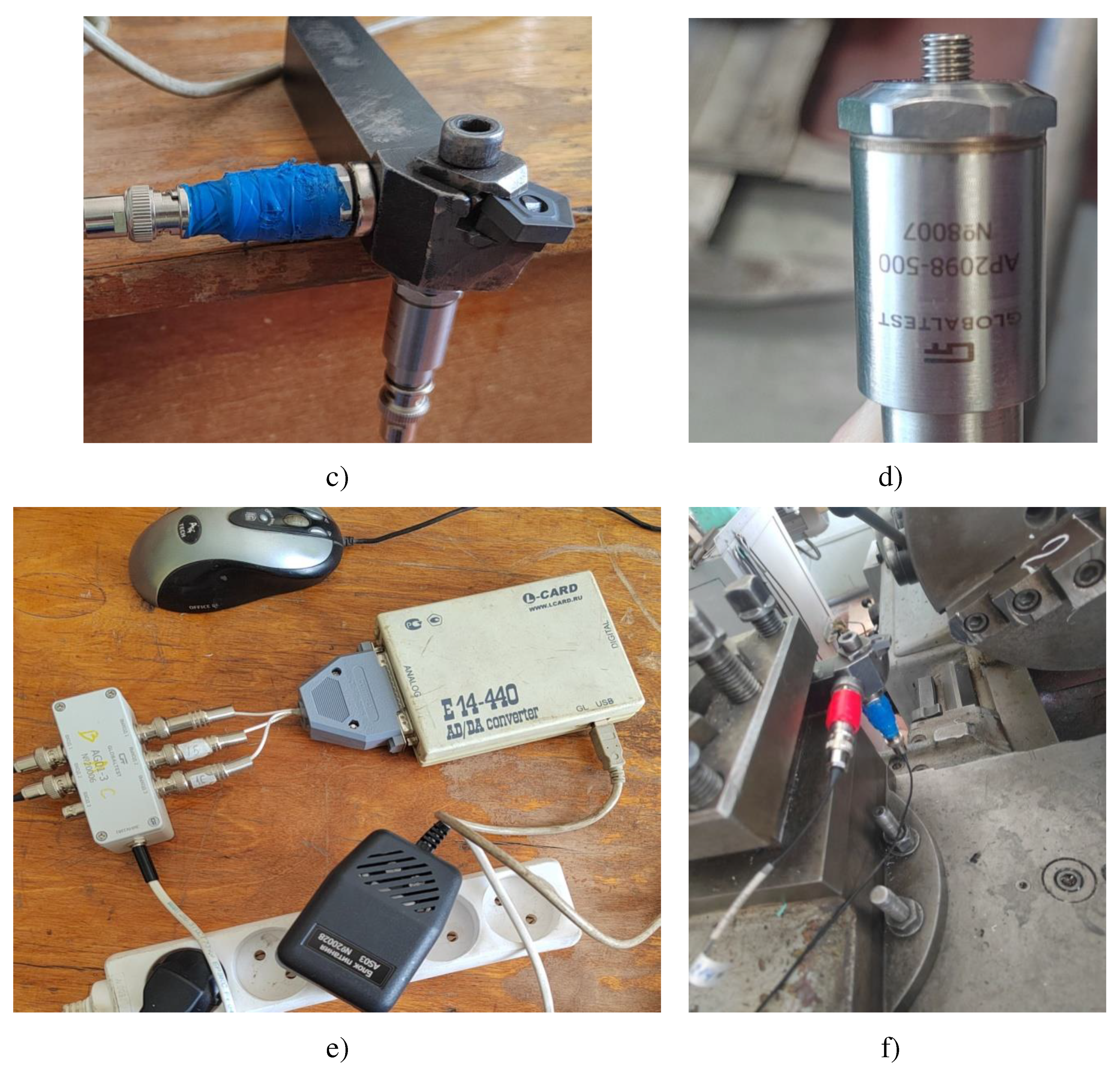
Figure 4.
ADC program interface, a) parameter input window, b) measurement data output window.
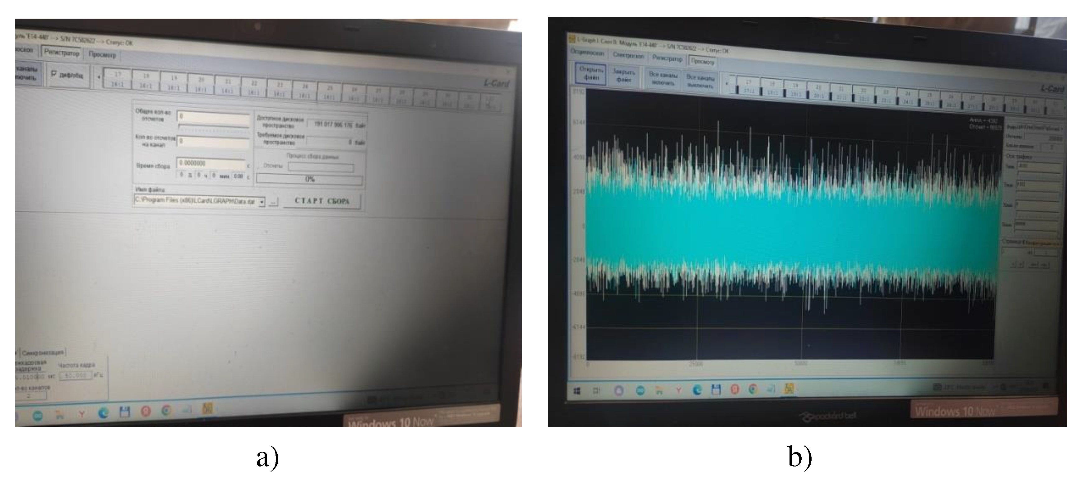
Figure 5.
Experimental data for the case of the cutting speed of 140 m/min: a) the measured signal of vibration acceleration in the direction of z axis, b) the average value of vibration velocity in the direction of z axis obtained as a result of integration and subtraction, c) the average value of vibration displacements in the direction of z axis obtained as a result of double integration and subtraction.
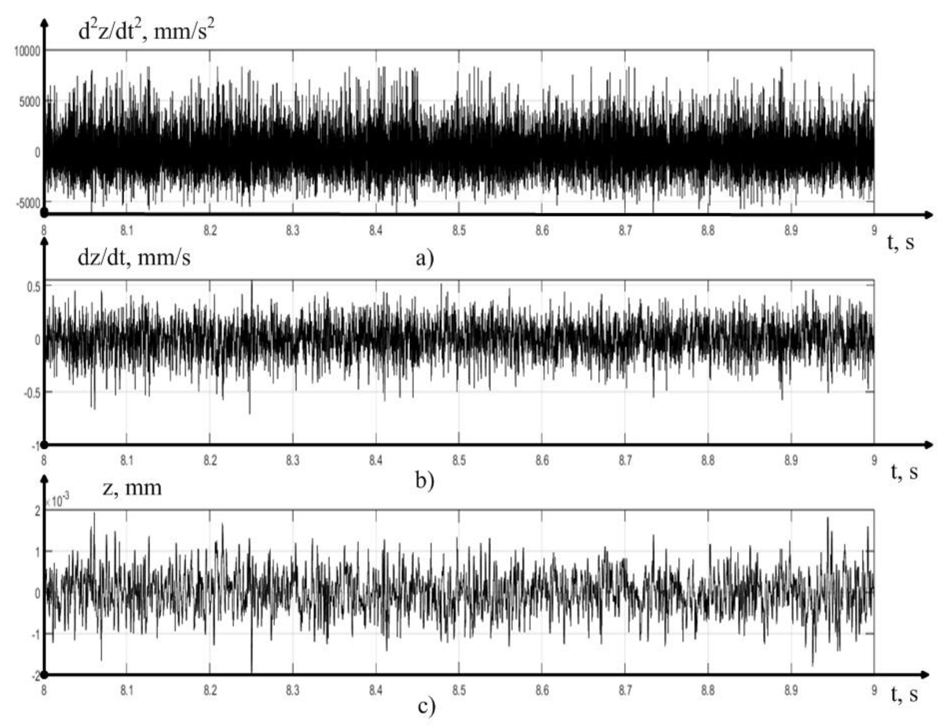
Figure 6.
Signal power spectra: a) measured vibration acceleration signal in the direction of z axis, b) vibration velocity in the direction of z axis, c) vibration displacements in the direction of z axis.
Figure 6.
Signal power spectra: a) measured vibration acceleration signal in the direction of z axis, b) vibration velocity in the direction of z axis, c) vibration displacements in the direction of z axis.
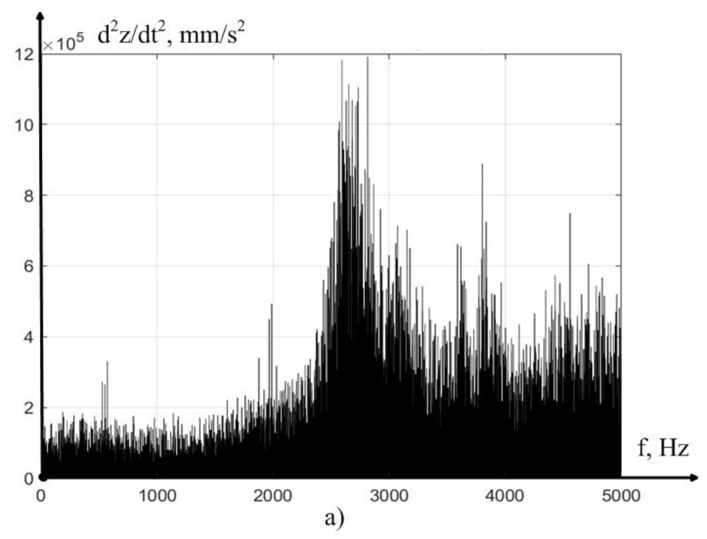
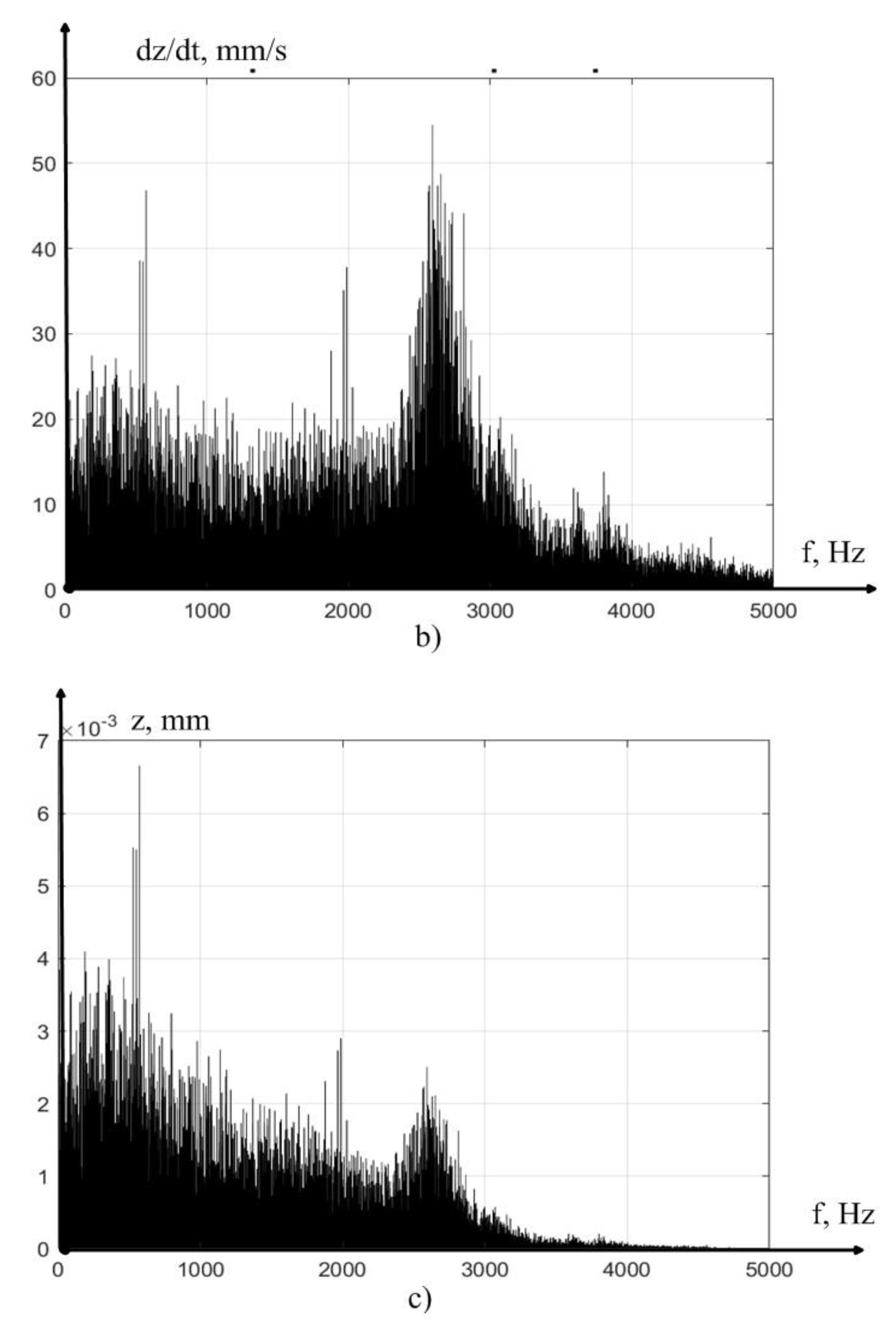
Figure 7.
Areas of stabilization of the cutting force.
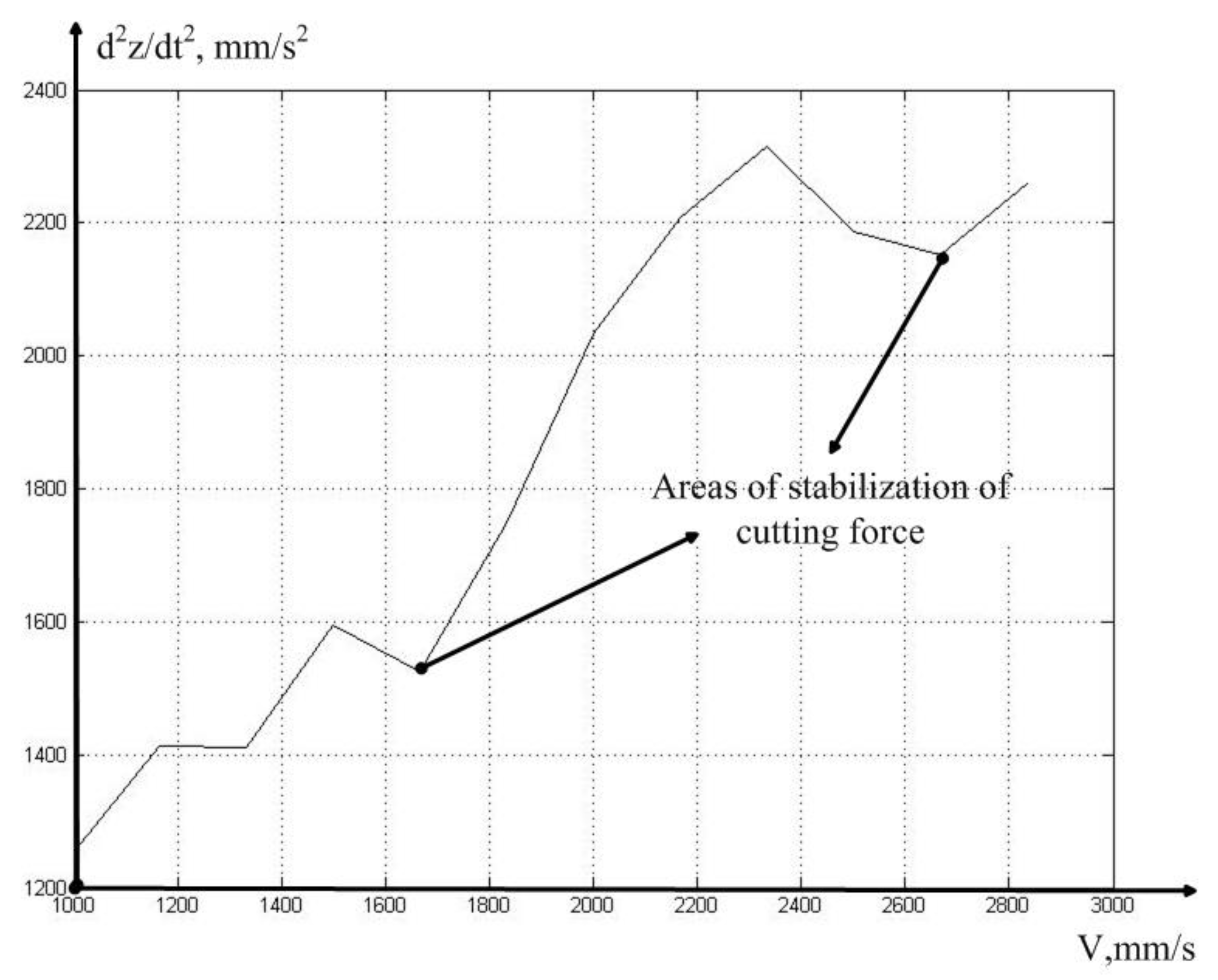
Figure 8.
The value of the actual feed a) and the corresponding value of the time constant b) for the case of cutting at the speed of 160 meters per minute.
Figure 8.
The value of the actual feed a) and the corresponding value of the time constant b) for the case of cutting at the speed of 160 meters per minute.
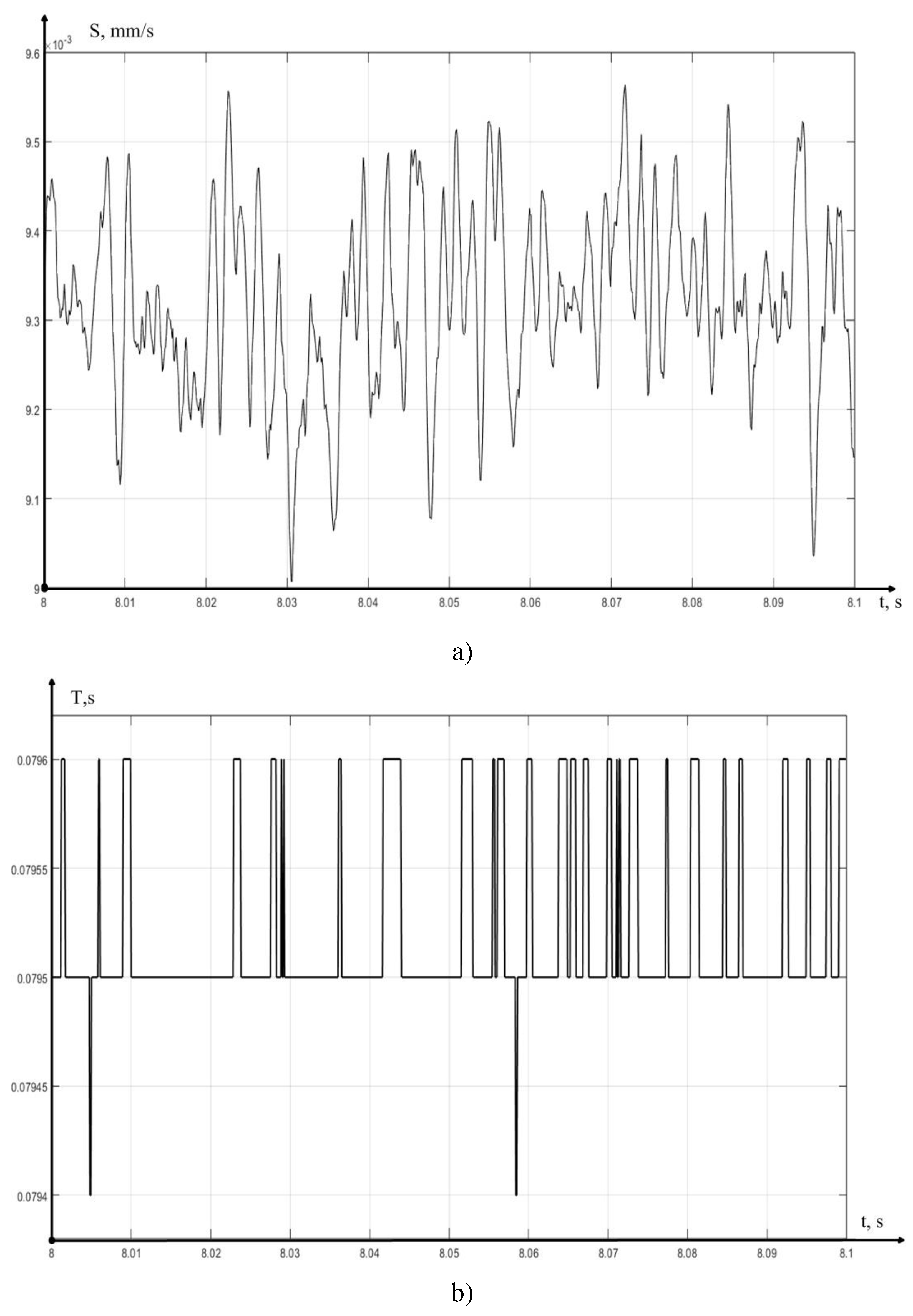
Figure 9.
MCP of the feed value minus the set value.
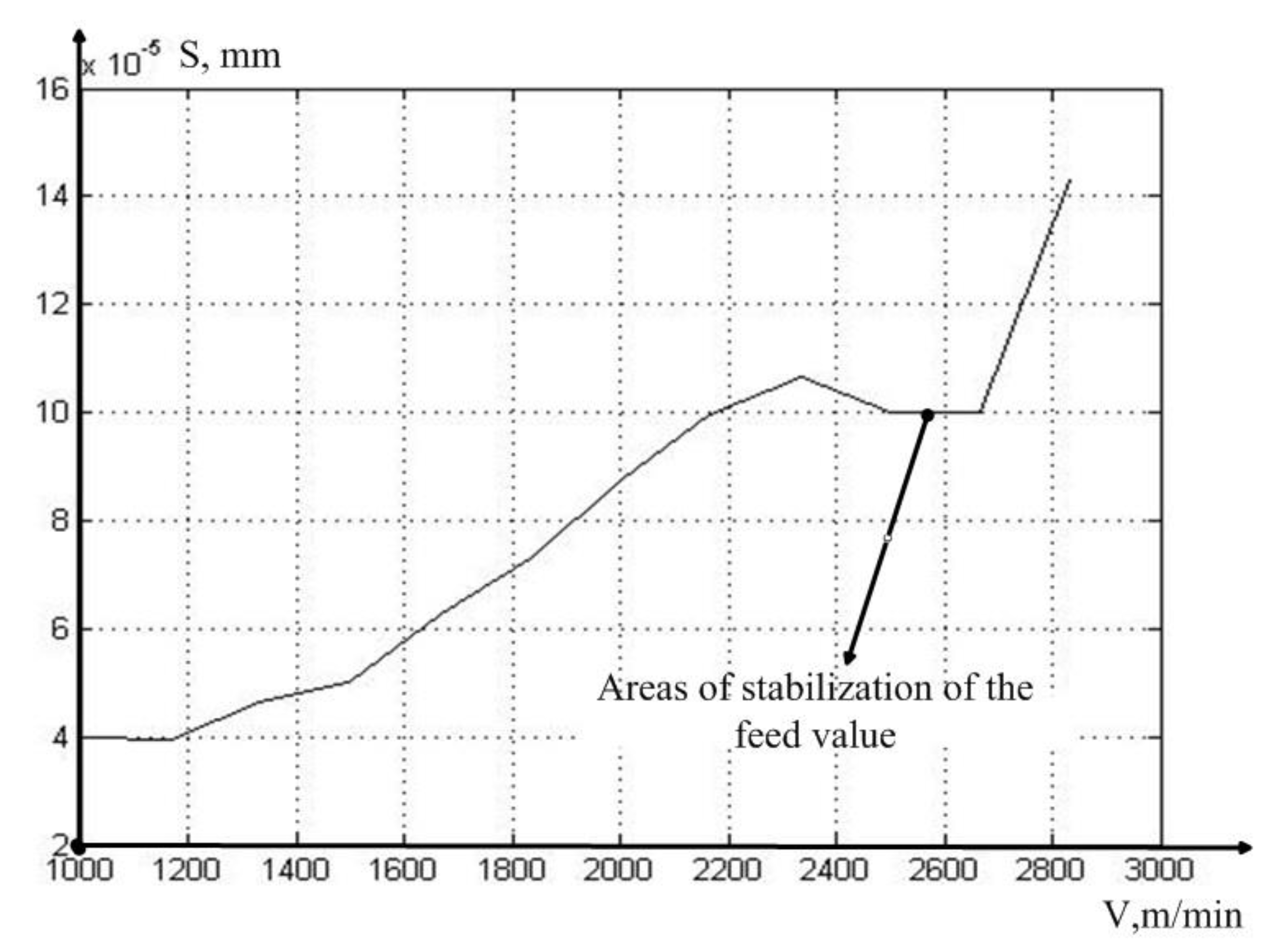

Table 1.
Results of experimental data processing.
| Cutting speed, m/min | RMS value of vibration accelerations | ||
| First Channel (x) | Second Channel (x) (z) | General about 2 channels | |
| 60 | 1026 | 1253 | 1145 |
| 70 | 1113 | 1414 | 1273 |
| 80 | 1132 | 1411 | 1279 |
| 90 | 1226 | 1596 | 1423 |
| 100 | 1455 | 1524 | 1490 |
| 110 | 1681 | 1748 | 1715 |
| 120 | 1883 | 2033 | 1959 |
| 130 | 2036 | 2207 | 2123 |
| 140 | 2268 | 2316 | 2292 |
| 150 | 2393 | 2187 | 2292 |
| 160 | 2505 | 2152 | 2335 |
| 170 | 2648 | 2260 | 2462 |
Table 2.
MCP of the feed value minus the set value.
| Cutting speed, m/min | The RMS value of the feed value minus the set value |
| 60 | 0.000039749 |
| 70 | 0.000039437 |
| 80 | 0.000046507 |
| 90 | 0.000050033 |
| 100 | 0.000062787 |
| 110 | 0.000072894 |
| 120 | 0.000087393 |
| 130 | 0.000099597 |
| 140 | 0.00010672 |
| 150 | 0.00010003 |
| 160 | 0.00010015 |
| 170 | 0.00014305 |
Disclaimer/Publisher’s Note: The statements, opinions and data contained in all publications are solely those of the individual author(s) and contributor(s) and not of MDPI and/or the editor(s). MDPI and/or the editor(s) disclaim responsibility for any injury to people or property resulting from any ideas, methods, instructions or products referred to in the content. |
© 2023 by the authors. Licensee MDPI, Basel, Switzerland. This article is an open access article distributed under the terms and conditions of the Creative Commons Attribution (CC BY) license (http://creativecommons.org/licenses/by/4.0/).
Copyright: This open access article is published under a Creative Commons CC BY 4.0 license, which permit the free download, distribution, and reuse, provided that the author and preprint are cited in any reuse.


