
Submitted:
19 November 2025
Posted:
20 November 2025
Read the latest preprint version here
Abstract
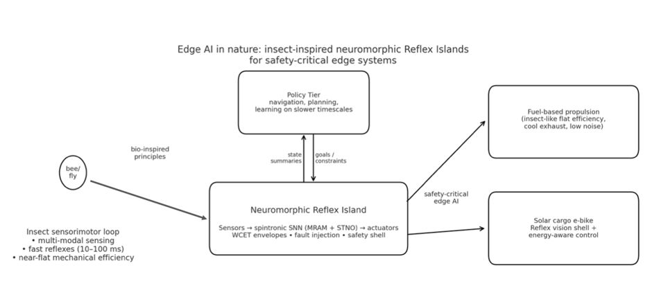
Insects achieve millisecond sensor–motor loops with tiny sensors, compact neural circuits, and powerful actuators, embodying the principles of Edge AI. We present a comprehensive architectural blueprint translating insect neurobiology into a hardware–software stack: a latency-first control hierarchy that partitions tasks between a fast, dedicated Reflex Tier and a slower, robust Policy Tier, with explicit WCET envelopes and freedom-from-interference boundaries. This architecture is realized through a neuromorphic Reflex Island utilizing spintronic primitives, specifically MRAM synapses (for non-volatile, innate memory) and spin-torque nano-oscillator (STNO) reservoirs (for temporal processing), to enable instant-on, memory-centric reflexes [10–16]. Furthermore, we formalize the biological governance mechanisms, demonstrating that unlike conventional ICEs and miniturbines that exhibit narrow best-efficiency islands, insects utilize active thermoregulation and DGC (Discontinuous Gas Exchange) to maintain nearly constant energy efficiency across a broad operational load by actively managing their thermal set-point, which we map into thermal-debt and burst-budget controllers [17–33]. We instantiate this integrated bio-inspired model in an insect-like IFEVS thruster, a solar cargo e-bike with a neuromorphic safety shell, and other safety-critical edge systems, providing concrete efficiency comparisons, latency and energy budgets, and safety-case hooks that support certification and adoption across autonomous domains [6,11,14,28].
Keywords:
edge AI
; insect inspired control
; optic flow
; halteres
; discontinuous gas exchange
; thermoregulation
; neuromorphic computing
; spintronics
; MRAM
; STNO
; WCET
1. Introduction: Insects as Canonical Edge-AI Systems
Glossary table
- Reflex Tier — fastest safety-critical control with hard deadlines (Control).
- Reflex Island — isolated near-sensor partition executing the Reflex Tier (Platform).
- Reflex substrate (spintronic/CMOS) — technology implementing the Reflex Tier (Platform).
- Policy Tier — slower mapping/planning; publishes goals to Reflex (Control)
- FFI (freedom-from-interference) — faults/jitter in Policy can’t affect Reflex (Safety).
- ASIL allocation — ISO 26262 safety level assignment per function (Safety).
- DGC (Discontinuous Gas Exchange) — Closed–Flutter–Open; analogy for idle I/O gating (Biology↔Firmware).
- Thermal debt — required cool-down after a burst (Thermal).
- Set-point temperature — maintained flight-muscle band during work (Thermal/Biology).
Cooling conductance
- — linearized convection + radiation loss (Physics).
Thermal time constant
- — response time; scales roughly with size (Physics).
- Prime mover — fuel engine/turbine kept at efficiency island (Propulsion).
- Cold-to-idle latency — light-off to usable idle time (Propulsion).
- BSFC map — brake-specific fuel consumption vs rpm/load (Efficiency).
- Injection event (micro-injection) — one pulse in a split injection (Engines).
- Thoracic shivering — pre-flight warm-up of flight muscles (Biology/Thermal).
- Optic flow — wide-field visual motion cue (Sensing).
- Halteres — gyroscopic sensory organs in Diptera (Sensing).
- Dorsal Rim Area (DRA) — polarization-sensitive zone for celestial compass (Sensing).
- Central Complex (ring attractor) — neural compass with an activity bump (Control/Biology).
- CPG (central pattern generator) — rhythmic actuation circuit (Control/Biology).
- STNO reservoir — spin-torque oscillator network for temporal processing (Hardware).
- MRAM synapse — non-volatile weight (MTJ) for instant-on reflex (Hardware).
- DVFS — dynamic voltage/frequency scaling under thermal control (Platform).
- WCET envelope — worst-case execution-time budget from sensor exposure to actuator update, including safety margin, defined per Reflex loop (Timing/Safety).
Insects execute navigation, stabilization, landing, foraging, and escape entirely on-device, using parallel sensors (compound eyes, ocelli, halteres, antennae) connected by short neural pathways to actuators with ms-range latency [1,2,3,4]. They fuse wide-field optic flow with inertial/gyroscopic signals for phase-locked wing control [1,2,3], mapping well to latency-first embedded loops in robotics and vehicles. Their neural organization cleanly separates fast stabilization from slower planning/learning, matching the Reflex/Policy split we adopt [5,6,7,8,9].
1.1. The Fly (Stabilization Specialist)
Flies combine halteres (mechanical gyroscopes) with wide-field vision to stabilize attitude within tens of milliseconds [1,2,3]. A “giant-fiber” pathway triggers evasive maneuvers with minimal synapses, illustrating an architectural bias for short, deterministic, high-priority reflexes [4,5].
The fly is the archetype of the ultra-low-latency control system, focused relentlessly on stabilization and rapid evasive maneuvers. Its architecture is designed for speed, relying on high-bandwidth sensors (like the halteres and compound eyes) connected by short, dedicated neural pathways to achieve response times measured in milliseconds, making it the perfect biological analogy for the Edge-AI Reflex Tier.
| Component | Description and Function | Edge-AI Analogy |
| Sensors (Fast & Complementary) | "Compound eyes (wide FOV, very high temporal resolution); Ocelli (simple light sensors for attitude); Halteres (gyroscopes sensing body rotation via Coriolis forces); Antennae/hairs (airflow and vibration)." | IMU/Gyroscopes + Global-shutter/Event Cameras + Airflow Sensors. |
| On-board Computation | "Optic lobe motion detectors (parallel ""flow"" filters); Reflex pathways (e.g., ""giant fiber"" escape route) prioritizing latency; Central complex (orientation); Mushroom bodies (learning)." | Fixed-function accelerators (for optic flow); Low-latency neuromorphic circuits (Reflex Tier). |
| Control Loops | Inner Loop (Stabilization): halteres + ocelli + wide-field motion → wing adjustments in a few–tens of ms. Outer Loop (Goal): visual flow + odor/airflow → course/target selection over longer windows. | Two-tier control: Reflex Tier (µs-ms) for stabilization; Policy Tier (ms-s) for planning. |
Edge-AI Lesson: Push stabilization to hard-real-time reflex loops near sensors; keep planning separate and slower. Use IMU/"gyros" + fast flow sensors, fuse them, and actuate at kHz rates.
Figure 1.
A schematic diagram illustrating the tight sensor-compute-actuation loop in Drosophila [1,2,3,4,5].
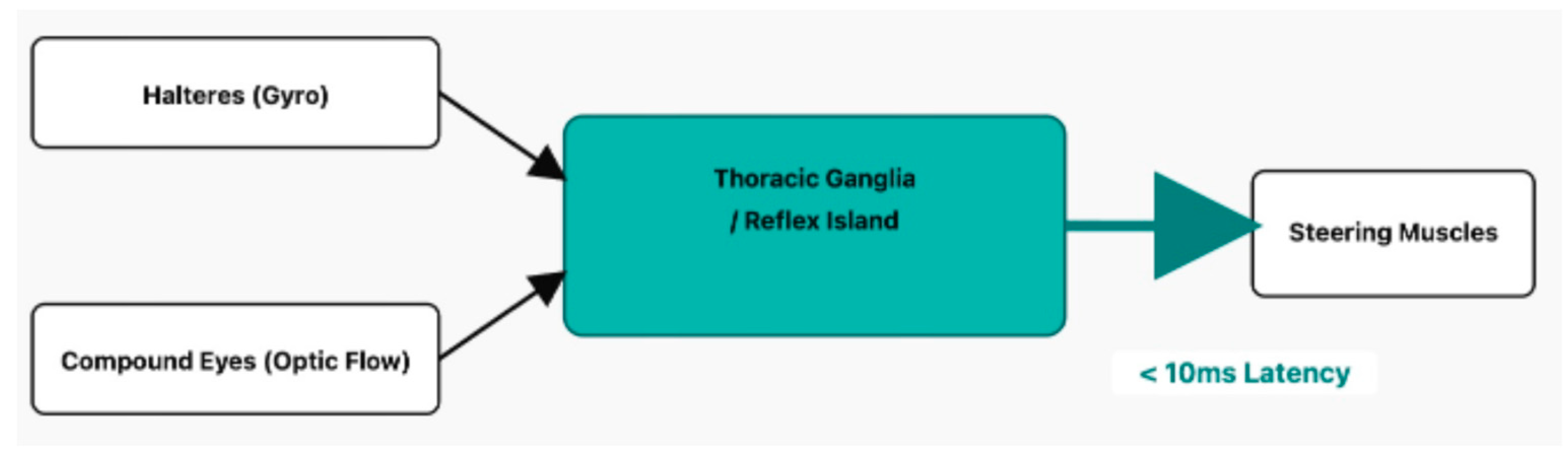
Core Concept: A minimalist, hard-real-time control loop where the gyroscope (Halteres) and optic flow (Eyes) are fused to control the wings.
- Sensing: The halteres detect angular velocity via Coriolis forces, while the compound eyes detect wide-field optic flow.
- Compute (Fusion): These two streams are fused in thoracic reflex loops, creating a complementary filter where halteres handle fast perturbations and vision handles slow drift.
- Actuation: The resulting error signal directly modulates the phase and amplitude of tiny steering muscles, making micro-adjustments at each wingbeat to stabilize attitude.
1.2. The Bee (Navigation And Task Specialist)
Bees add robust heuristics for speed control and landing e.g., holding optic-flow expansion roughly constant as well as a celestial compass (polarization sensitivity) for long-range navigation [6,7,8,9]. In the central complex, ring-attractor circuits maintain a persistent heading “bump,” providing a compact Policy signal to bias reflexes [8,9].
While the fly excels at ultra-low-latency reflexes, the bee represents an Edge-AI system optimized for robust, long-range navigation and complex task execution, relying heavily on stable internal cues and learned heuristics. It is a specialist in path integration and associative learning, which are critical features for modern Edge-AI used in persistent monitoring or delivery tasks.
| Component | Description and Function | Edge-AI Analogy |
| Sensors | Compound eyes (incl. UV) + polarization sensitivity (sun compass); Ocelli (attitude); Antennae (olfaction + mechanosensation); Body hairs (micro-climate). | Polarization/UV Sensors; Odorimeters; Temperature/Contact Sensors. |
| On-board Computation | Optic flow odometry (distance estimation); Central complex (heading/compass and path integration); Mushroom bodies (associative learning); Task switching with minimal memory. | Visual Odometry (2D V-SLAM); Rule-based Policies (Heuristics); Local Learning (small neural networks). |
| Control Loops | Landing/Altitude: Maintain constant optic-flow expansion → smooth landings without absolute altitude. Navigation: Polarization compass + optic-flow odometer + odor cues → waypoint-style guidance. | "Non-linear control based on heuristics (e.g., adaptive Proportional-Integral-Derivative); Low-cost sensor fusion." |
- Sensing: As the bee approaches a surface, the visual image of the ground expands on its retina. The rate of this expansion (dalpha/dt) is computed.
- Policy: The bee's control policy is a simple heuristic: "Modulate thrust to keep the optic expansion rate constant."
- Actuation: If expansion is too fast, the bee increases thrust; if too slow, it decreases thrust.
- Compute (Integration): Specialized neural circuits integrate the e-vector orientation to maintain a stable global heading, even when the sun is obscured.
- Policy: This stable heading signal feeds into the Policy Tier (Central Complex) to bias the path integration and course selection, providing a low-cost, long-range compass.
Figure 5.
A schematic diagram illustrating the insect's internal head-direction system Central Complex Ring-Attractor (Flies/Bees) [8,9].
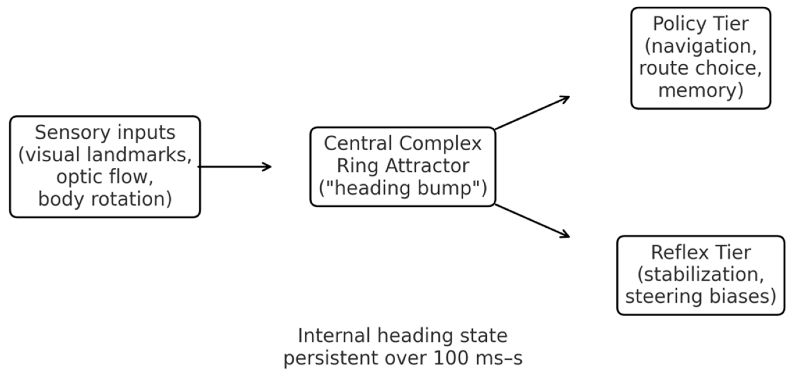
- Sensing/Input: Visual and proprioceptive inputs (e.g., optic flow, haltere signals) provide cues about angular velocity and landmarks.
- Compute (Ring Attractor): The Central Complex (specifically the Protocerebral Bridge) implements a recurrent neural network known as a ring attractor.
- This circuit maintains a persistent "bump" of activity that represents the animal's current heading.
- Policy: The position of the bump acts as a stable, internal state variable, a heading set-point that biases downstream motor reflexes, separating the high-level goal (direction) from low-level execution (torque).
Figure 2.
A: The bee as navigation and task specialist, Reflex vs Policy. Schematic overview of how multi-modal sensing (wide-field vision, polarized-sky compass, odor and wind cues) feeds into fast navigation Reflex pathways and slower Policy/Task pathways in the bee brain. The upper “Reflex Tier” slice represents short-latency loops for corridor centering, obstacle avoidance and landing; the lower “Policy Tier” slice summarizes slower path integration, route memory and value-based foraging decisions. Actions (flight path, task switching, waggle communication) emerge from the combined influence of these tiers, providing the biological template for our Edge-AI Reflex Islands and Policy layer.
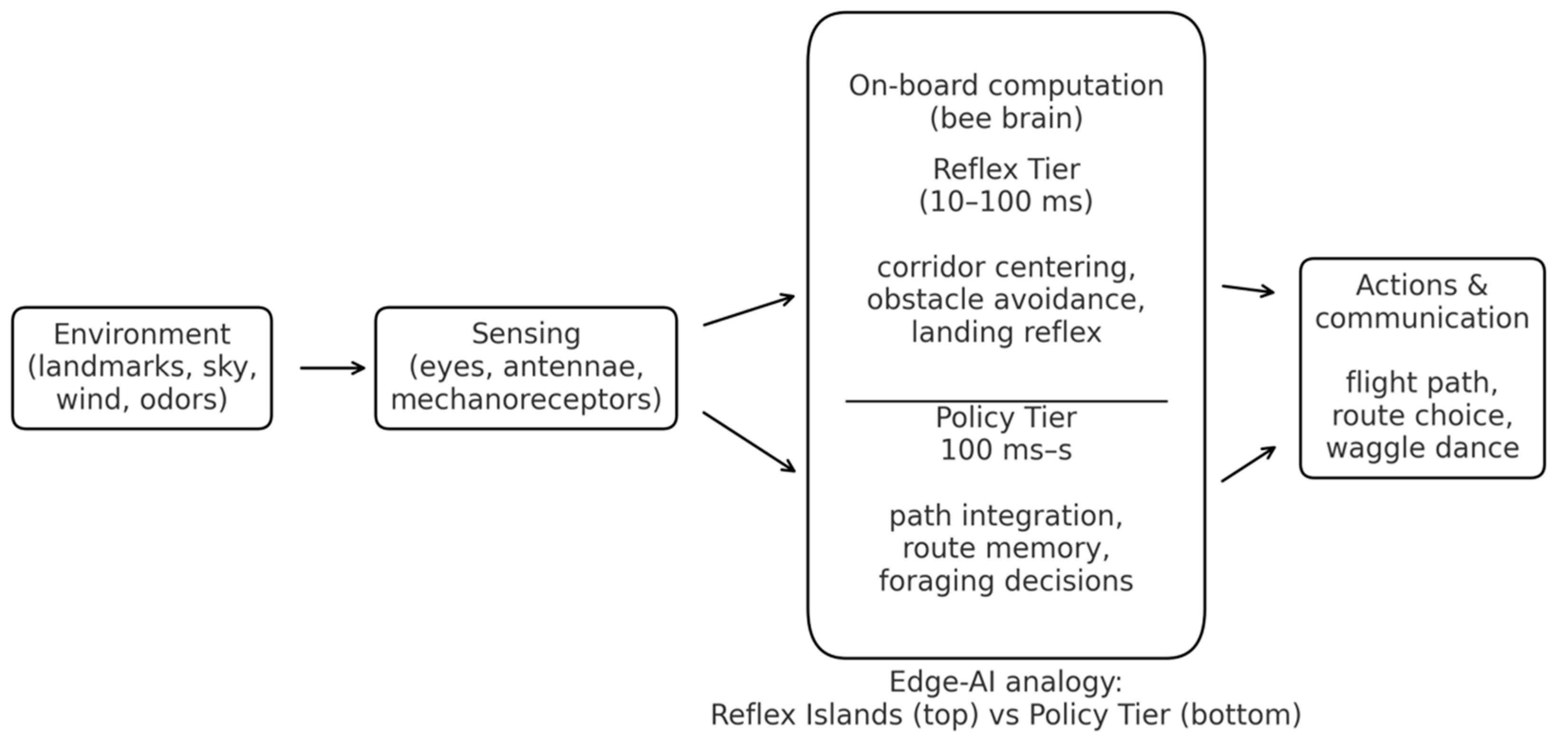
Edge-AI Lesson: Use cheap cues (flow, polarization, brightness) to compute robust control signals without heavy models. Keep local learning (simple associations) at the Edge.
Figure 3.
B: Bee landing control via optic flow. During landing, the bee observes an expanding ground pattern; the visual angle
Figure 3.
B: Bee landing control via optic flow. During landing, the bee observes an expanding ground pattern; the visual angle
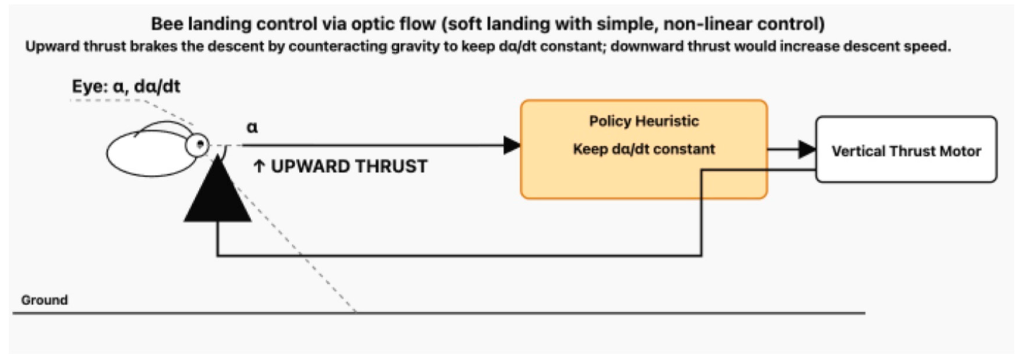
between the eye and the touchdown point increases as the bee approaches. A simple heuristic keeps the angular expansion rate approximately constant, which yields an exponential deceleration and soft landing [6]. An optic-flow sensor provides and to a non-linear landing controller; increasing upward thrust brakes the descent to hold constant, whereas reducing thrust allows gravity to dominate and increases descent speed.
This simple, non-linear control loop automatically results in a smooth, decelerating touchdown without needing to know its absolute altitude h.
Figure 4.
A schematic diagram illustrating the bee's robust, low-bandwidth navigation system [7].
Figure 4.
A schematic diagram illustrating the bee's robust, low-bandwidth navigation system [7].
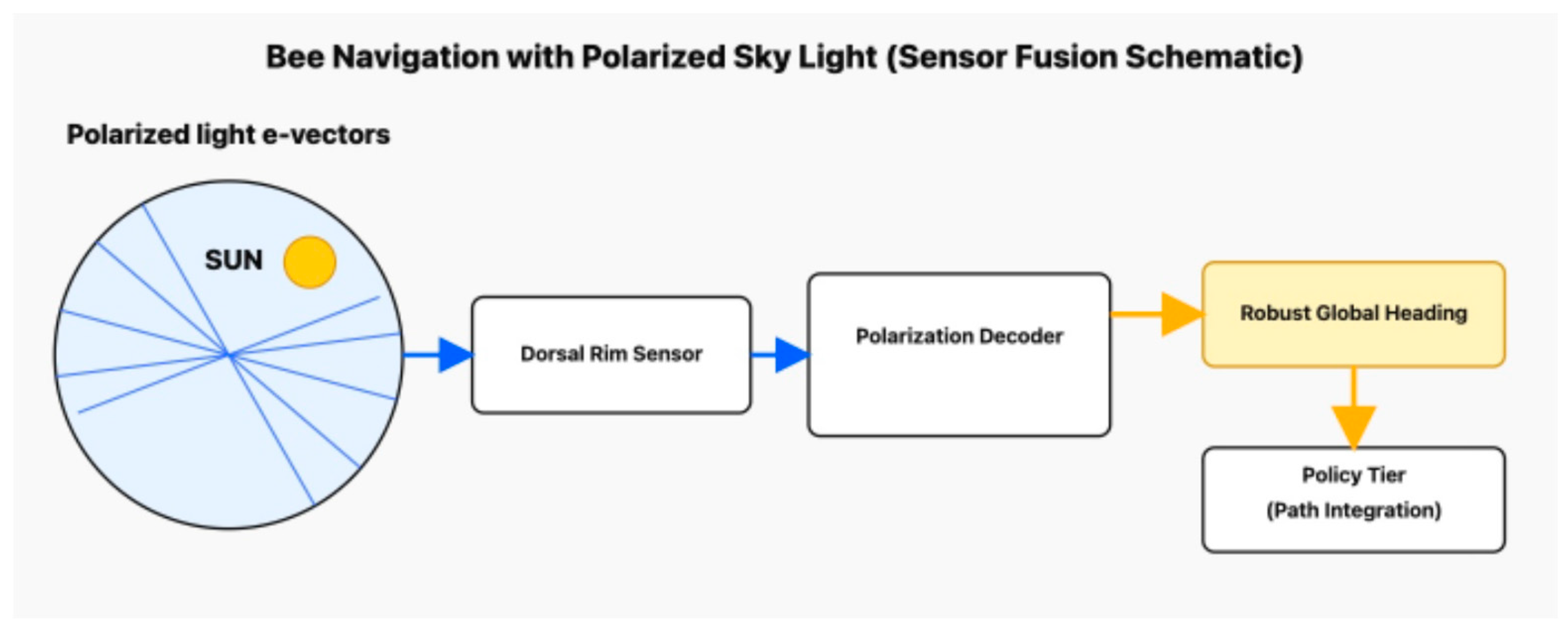
Sensing: UV photoreceptors in the dorsal rim of the compound eye detect the pattern of polarized light in the sky, which is fixed relative to the sun's position.
2. Latency-First Architecture (Biology → Engineering)
Insect biology provides a model for a two-tier control architecture, essential for safety-critical Edge-AI systems: it prioritizes the speed and reliability of local reflexes over the complexity of global planning. This latency-first approach ensures that critical stabilization and emergency responses occur via the shortest, most deterministic pathway possible.
Two-Tier Control
We implement two tiers: a Reflex Tier (near sensors/actuators; µs–ms) and a Policy Tier (ms–s), communicating via timestamped, lock-free queues. Reflex handles stabilization and safety; Policy handles mapping, heuristics, and goals. This mirrors insect hierarchies and makes timing budgets analyzable for safety certification [4,5,10,11]. Design principles are: co-locate sensors/compute/drivers; wire interrupt → DMA → neuromorphic Reflex → RT core → PWM/FOC; hold end-to-end stabilization <5 ms with critical safeties <1 ms; and export only goal states upstream.
| Biological Tier | Engineering Tier | Typical Latency | Function |
| Reflex | Reflex Tier (Neuromorphic Island) | Microseconds–Milliseconds (µs–ms) | "Stabilization, immediate reactions, low-level control (e.g., halteres → steering muscles)." |
| Policy | Policy Tier (RT Core/NPU) | Tens–Hundreds of Milliseconds (ms–s) | "Navigation, path planning, associative learning, goal selection (e.g., central complex → reflexes)." |
Table 1 gives an illustrative WCET envelope for a reference Reflex loop inspired by “haltere + optic flow → steering muscles”, instantiated on a representative automotive stack (AURIX-class MCU + MRAM device + Loihi-class SNN). Times are worst-case at the hot electrical corner (high temperature, low voltage), including guard bands.
Example stack: Infineon AURIX TC39x (300 MHz, 40 nm), Everspin STT-MRAM (35 ns access), Loihi 2-class SNN core (14 nm, ~2 µJ/inference). Times are worst-case at 125°C, 85% Vmin.
The resulting end-to-end Reflex WCET is 3.4 ms against a 5 ms design budget, leaving ≈32% margin. Critical hardwired safety paths (e.g., limit-switch or E-stop → power stage) bypass the neuromorphic layers entirely and are kept below 1 ms. The table is not meant as a new benchmark, but as a concrete example of how the latency-first architecture supports WCET reasoning at the component and loop level.
3. Neuromorphic and Spintronic Hardware
The physical implementation of insect Edge-AI principles finds a natural analogy in neuromorphic and spintronic technologies.
3.1. Why Neuromorphic Matches the Insect Edge
Spiking Neural Networks (SNNs) are the central concept of neuromorphic computing and directly mirror insect neural codes: computation occurs only on significant changes in input (events), not on continuous data streams. This event-driven nature drastically reduces data movement and power consumption while maintaining the µs–ms responsiveness required for reflexes. SNNs naturally handle temporal coding and oscillations, which maps directly to biological principles like Central Pattern Generators (CPGs) and the rhythmic phase control necessary for insect flight timing. Furthermore, the inherent architecture of neuromorphic chips, with memory co-located or interwoven with processing elements supports local, on-device adaptation (e.g., STDP-like plasticity), similar to the associative learning observed in the insect mushroom bodies, bypassing the need to send large datasets to the cloud for learning updates. Spiking computation is event-driven and temporal, reducing data movement and power while meeting µs–ms latency; it naturally supports oscillations/CPGs and online adaptation [12,13,14].
To realize the Reflex Island, the SNN architecture should be a hybrid model: an initial Feed-Forward SNN (FF-SNN) layer executes rapid event filtering and early feature extraction (e.g., elementary motion detectors for optic flow), which then feeds into the core Recurrent SNN (RSNN) / Spintronic Reservoir layer responsible for state-space integration (e.g., haltere-visual fusion). Benchmarks for this layer must target ultra-low latency (end-to-end tau < 5ms with extreme energy efficiency (aiming for power consumption of < 1pJ or total power < 1mW for the dedicated reflex loop), aligning the system with the insect’s goal of continuous, deterministic stabilization.
Spiking neuromorphic hardware has already been validated at scale on several platforms: Intel’s Loihi chips for on-chip learning, the SpiNNaker many-core machine, IBM’s TrueNorth neurosynaptic processor, and BrainChip’s Akida edge SoC, all of which demonstrate low-power, event-driven inference in real applications [13,62,63,64].
3.2. Spintronic Primitives as "Physical Synapses and Neurons"
Spintronic devices offer the ideal physical building blocks for constructing the ultra-low-power, instant-on "Reflex Island". Their fundamental advantage is that they are "memory-centric," enabling computation to happen at the site of memory. This approach directly attacks the primary bottleneck in conventional computing, the energy and latency cost of moving data between a separate processor and memory, which is precisely the problem insects solve with their short, efficient neural pathways.
This spintronic-neuromorphic architecture is built from two key components:
- MRAM synapses (MTJs). Non-volatile, instant-on “innate” reflex weights, perfect for a cold-start Reflex Island [10,15]. The "synapses," which store the network's knowledge, are implemented using Magnetic RAM (MRAM). These are physical analogs for synapses, built from Magnetic Tunnel Junctions (MTJs). Their most critical property is non-volatility: they store the synaptic weights (the "innate reflexes") permanently, without requiring any power. This provides two transformative advantages for an edge device:
Instant-On Capability: The MRAM-based "Reflex Island" is instantly ready to compute when an event arrives, as the reflexes are physically embedded, emulating the "innate memory" of a biological reflex.
Energy Efficiency: By eliminating standby power for memory, this architecture drastically reduces overall power consumption, mirroring an insect's low metabolic rate at rest.
Together they yield a memory-centric, event-driven, instant-on reflex substrate aligned with insect physiology [10,11,12,13,14,15,16]. The "neurons," which process information, are implemented using Spin-Torque Nano-Oscillators (STNOs). These are compact, high-frequency (GHz) oscillators that naturally function as spiking neurons. Their unique strength is processing temporal information. STNOs are ideal for this, especially when configured as Reservoir Computers. An "STNO reservoir" is a complex, dynamic system of oscillators that can take high-speed temporal data streams (like from an event camera or IMU) and perform powerful sensorimotor transformations, making them a perfect fit for complex tasks like optic flow analysis and stabilization control.
The resulting MRAM–STNO stack is not speculative: it is explicitly tracked in industrial roadmaps such as the IRDS ‘Emerging Research Devices/Beyond CMOS’ chapter, the 2022 Roadmap on Neuromorphic Computing and Engineering, and the SRC/SIA Decadal Plan for Semiconductors, all of which identify spintronic memories and oscillators as leading candidates for ultra-low-power, neuromorphic compute fabrics [56,65,66,67].
While the MRAM synapse is mature (TRL 8-9) and already commercialized for non-volatile memory, the STNO-based reservoir neuron remains at mid-development (TRL 4-5) due to integration challenges; consequently, the full Reflex Island chip incorporating both primitives for deterministic, event-driven control is realistically projected to achieve integrated laboratory prototypes (TRL 5-6) within 2-3 years, leading to initial deployment in specialized, latency-critical domains like micro-robotics or medical sensing (TRL 7+) within the next 5 years.
Commercial MRAM examples are: Everspin EMD3D256M16 (256 Mb, 35 ns, TRL 9); TSMC 22ULL eMRAM (16 Mb embedded, TRL 8); Avalanche MRAM-based accelerators (TRL 7–8). Per IRDS 2022, embedded STT-MRAM reached volume production in 2020–2022 at leading fabs.
Figure 6.
A schematic illustrating how spintronic devices implement insect Edge AI principles. Spintronics for Bio-Inspired Edge AI. Spintronic Architecture for the Reflex Island [10,15,16]. .
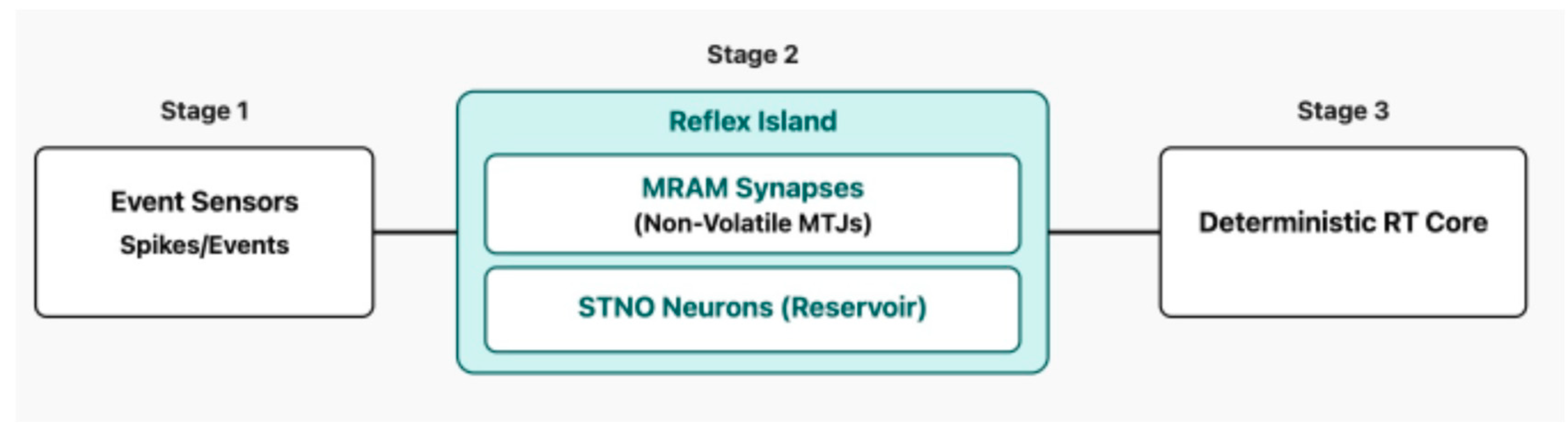
- Sensing: Event streams from sensors (e.g., event cameras, IMU) are converted into spikes (electrical pulses).
- Compute (MRAM Synapses): Magnetic Tunnel Junctions (MTJs) in MRAM act as non-volatile synapses, storing neural network weights directly where they are used. This enables instant-on capability and near-zero standby power, emulating innate memory and reflexes.
- Compute (STNO Neurons): Spin-Torque Nano-Oscillators (STNOs) act as compact, high-frequency (GHz) spiking neurons. They can form reservoirs for processing temporal tasks and sensorimotor transformation, such as optic flow analysis.
- Actuation (RT Core): The output (set-points) of the spintronic SNN feeds a deterministic Real-Time Core (RT Core) that performs final control (PID/LQR) and drives the actuators.
4. Thermoregulation, Frequency Control, and “Natural Engine” Analogies
Small flyers sit on an unforgiving surface-to-volume battlefield: heat is generated by volume but lost through surface. We formalize the physics, then build an intuitive efficiency comparison among insects, ICEs, and miniturbines.
4.1. Discontinuous Gas Exchange (DGC) and Idle I/O Gating
4.2. Thermal Governance as a State Machine
Insects actively control temperature during any phase of operation. This need for active control highlights a key advantage over conventional micro-scale propulsion systems: Unlike internal combustion engines or miniature turbines, which are power-limited by narrow best-efficiency islands due to strict thermal and mechanical tolerances, the insect decouples output power (frequency) from efficiency by actively maintaining a near-constant thermal set-point across a broad operational load. This biological mechanism gives the system superior operational flexibility and near-constant efficiency across the entire performance range, a crucial goal for Edge AI power management.
This insect-inspired thermal governance system formalizes burst budgeting as a predictive control loop that allows transient maximum power Pmax to temporarily exceed steady-state thermal dissipation based on the explicit assumption of a lumped thermal capacitance model tau for the critical component cluster (the Reflex Island); the permissible burst duration tburst is then dynamically calculated and corrected by a feedback term proportional to the current thermal debt Tdebt = Tcore - Tsetpoint and and environmental variable correction factor, predominantly the ambient temperature Tamb, to ensure the critical component temperature Tcrit is never exceeded.
In flight, insects actively thermoregulate: shivering warms thoracic muscles to a tight performance band; ventilatory/evaporative cooling and head–thorax heat partitioning hold neural function while exporting heat [21,22,23,24]. We mirror this with a firmware state machine: REST → WARM-UP → WORK → BURST → COOL-DOWN → FAULT-SAFE, always preserving Reflex deadlines while shedding Policy first.
4.3. Why Thermoregulation Tightens at Small Scale (Black-Body + Convection)
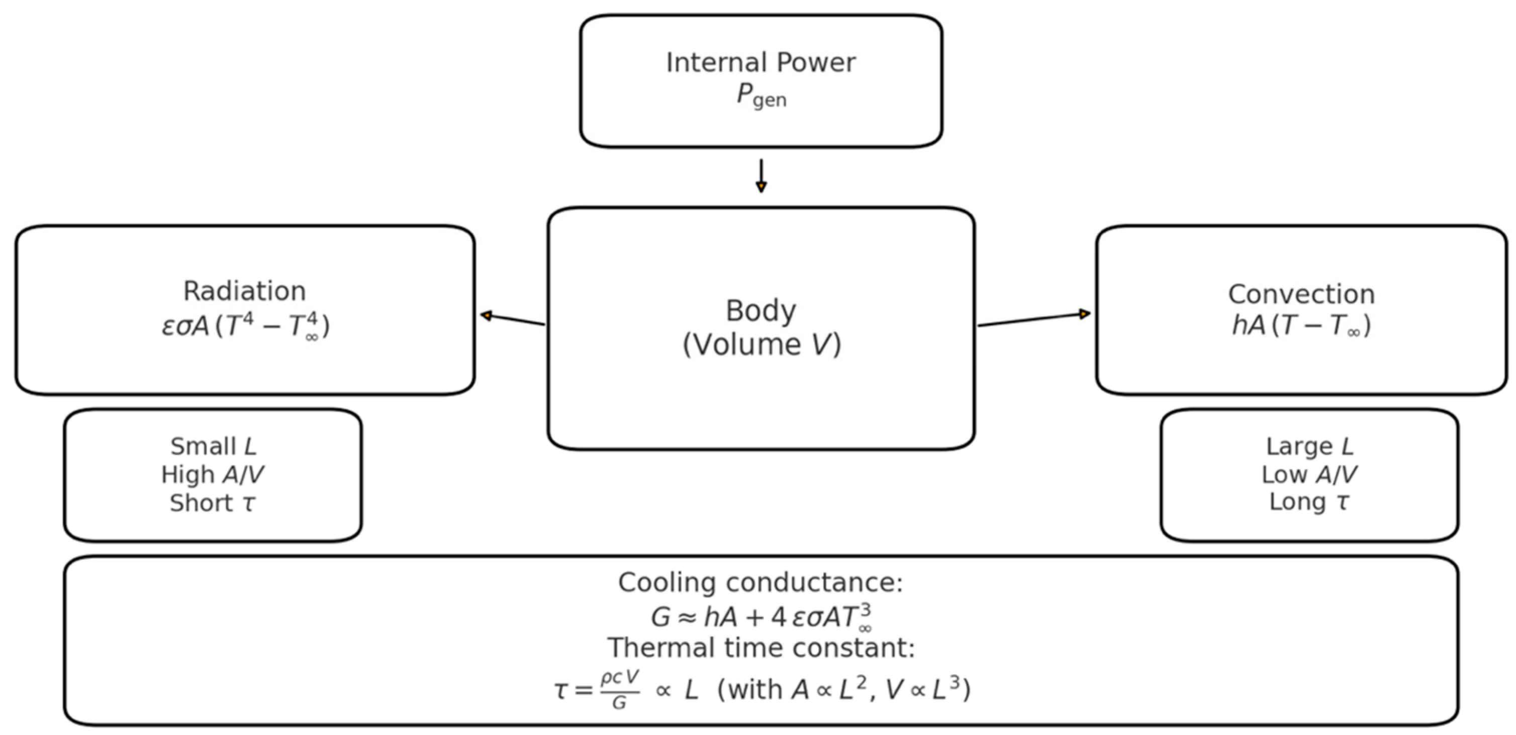
Small flyers sit on an unforgiving surface-to-volume battlefield: heat is generated by volume but lost through surface. A lumped heat balance for a body at temperature is:
with thermal capacitance , convection coefficient , emissivity , and the Stefan–Boltzmann constant . Linearizing radiation about ambient yields a combined cooling conductance:
so the dynamics reduce to a first-order form with thermal time constant . With characteristic length , and : smaller bodies (large ) heat and cool much faster, demanding active thermoregulation to hold performance set-points [25,26].
scaling (conceptual). Internal power enters the Body (volume ) and is balanced by Convection and Radiation . Linearizing radiation around ambient yields the cooling conductance and the thermal time constant . With and , : smaller → higher → shorter . Mini-panels summarize small- vs large-scale behavior.
Figure 7.
Heat balance with
4.4. A Four-Stroke “Natural Engine” for Insect Thermoregulation
Insects don't have distinct strokes; they modulate continuously, we reframe insect thermal cycles using four-stroke terminology familiar to engineers, not to imply mechanical equivalence but to aid conceptual mapping to firmware state machines:
WARM-UP (Compression) - shivering thermogenesis raises thoracic
- 2.
- 3.
- 4.
Figure 8.
A schematic diagram illustrating the state-dependent thermal management system. Thoracic Thermoregulation Control [22,23].
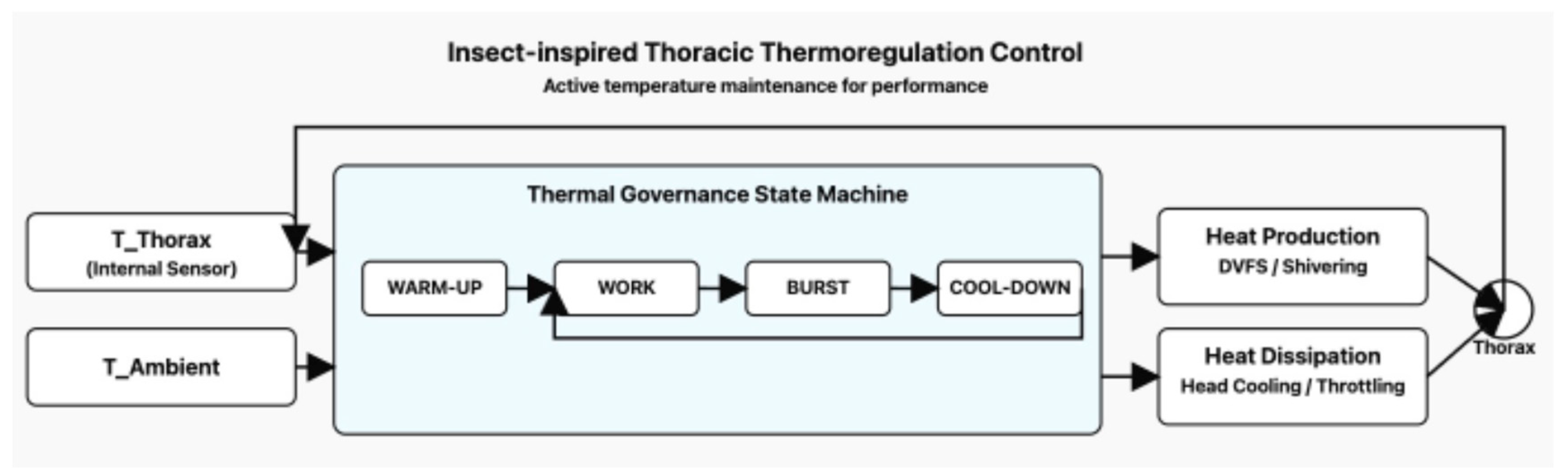
- Sensing: Thoracic temperature (for power output) and ambient temperature are monitored.
- Compute (Control): A central control mechanism (analogous to a firmware state machine) actively regulates heat production (e.g., shivering) and heat dissipation (e.g., head cooling/evaporative cooling) to maintain a performance-optimal thoracic temperature set-point.
- Engineering Analogy: This is mirrored by an Edge AI system's thermal governance, which uses a state machine to dynamically adjust power/clock frequency (DVFS) and sensor duty cycles based on thermal sensors and predicted load, allowing for short, high-performance bursts while preventing thermal runaway.
4.5. Propulsion Analogy: Injection/Wingbeat Frequency and Efficiency
4.5.1. Injection Event Frequency in ICEs
In a four-stroke engine each cylinder has one combustion event every two crank revolutions. If each event uses micro-injections, the per-cylinder injector command rate is
and for an even-fire engine with cylinders the aggregate scheduling rate is
4.5.2. Wingbeat Frequency in Insects
Wingbeat falls in the same 10²–10³ Hz decade but is produced by asynchronous flight muscle and thorax resonance: neural spikes gate contractions while frequency stems from elastic mechanics, enabling high-Q operation with modest compute. Honeybees hover at ≈230 Hz [32,33,34,35], some small dipterans exceed 1 kHz [32,33].
4.5.3. Efficiency Maps: Narrow Islands vs. Near-Flat Bands
ICEs (and Brayton turbines) display narrow best-efficiency islands (low BSFC or high specific efficiency) at particular power–rpm combinations; moving away, especially to low load, induces pumping and heat losses. Adjusting injection/ignition timing or increasing pulse frequency does not flatten the thermodynamic map [27,36,37].
Insects, by contrast, regulate power primarily by wingbeat frequency and stroke while maintaining thoracic temperature near an optimal set-point, so mechanical conversion efficiency varies only modestly across the functional range: frequency-based power, nearly constant efficiency [21,22,23,24,32,33,34,35]. Classical work-loop and respirometry studies [52,53,54] report mechanical efficiencies for flight muscle that fall in the ~10–15% range for several species and preparations, even as mechanical power output and wingbeat frequency vary by about a factor of three to four. Ellington [53] reports a calculated upper limit of 29% for hovering flight muscle efficiency if elastic storage is ignored, challenging the low-efficiency view. Syme [35], acknowledges asynchronous muscle efficiency in the 15-20% range, suggesting the muscle type itself is highly evolved for mechanical output. We can then confidently that insect flight muscle efficiency is not only high but exceeds 15% under maximal power output conditions, justifying the engineering focus on maintaining a thermal set-point to keep it operating near this maximal efficiency island regardless of external power demand.
Rather than attempt a precise meta-analysis of heterogeneous experiments, we summarize these data in Fig. 4.3 as a shaded efficiency band between 10% and 15% across a broad span of normalized mechanical power. This stands in contrast to the narrow high-efficiency peak sketched for ICEs and miniturbines, whose efficiency falls off steeply away from the island.
Insect flight muscle (specifically the asynchronous flight muscle used by flies, bees, and wasps) is a highly specialized engine whose mechanical efficiency is temperature-dependent.
- Optimal Temperature: The enzymes and contractile filaments within the muscle are designed to operate at a specific, elevated temperature (often 35oC to 40oC). At this thermal set-point, the muscle fibers achieve their maximum power output and mechanical efficiency (10%-15%).
- Active Regulation: The insect actively regulates its thoracic temperature to stay near this set-point. This means:
- If cold, the insect shivers (pre-flight warm-up) to generate waste heat and reach the set-point.
- During flight, if the power demand is low (generating less waste heat), the insect may actively reduce heat dissipation.
- Decoupling Power from Efficiency:By ensuring the muscle is always at its biomechanical "sweet spot," the insect can then adjust its mechanical power output simply by changing its wingbeat frequency (within limits) or adjusting its wing amplitude, without sacrificing its intrinsic mechanical
Insect flight muscle does not have perfectly flat efficiency, but its load dependence over the biologically relevant operating range is modest compared to conventional heat engines. This justifies the “near-flat band” representation adopted in Fig. 4.3 and underpins the propulsion analogy in Section 5, where we seek engineered systems whose prime movers behave more like insect flight muscle than like classical BSFC maps.
Figure 9.
Mechanical efficiency vs. normalized power for engines, miniturbines and insect flight muscle.
Figure 9.
Mechanical efficiency vs. normalized power for engines, miniturbines and insect flight muscle.
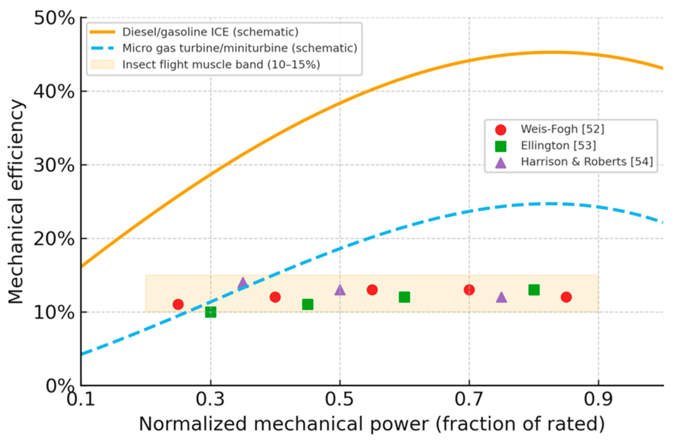
Mechanical efficiency as a function of normalized mechanical power (fraction of rated power). The solid curve shows a schematic diesel/gasoline ICE map with a broad peak around 45% efficiency at ~0.75 of rated power and modest degradation at full load as in standard BSFC maps [36,37]. The dashed curve shows a schematic micro gas turbine/miniturbine map representative of 200–400 N units, with peak efficiency ≲25% near 0.8 of rated power and pronounced losses at partial load. The shaded band indicates the ~10–15% mechanical efficiency range reported for insect flight muscle over a wide operating range, and the coloured symbols illustrate representative efficiencies from classical studies by Weis-Fogh [52], Ellington [53], Harrison & Roberts [54], Josephson[70] and Marden[71]. The curves are intentionally schematic but capture the qualitative contrast between narrow, load-sensitive engine maps and the comparatively weak load dependence of insect flight muscle.
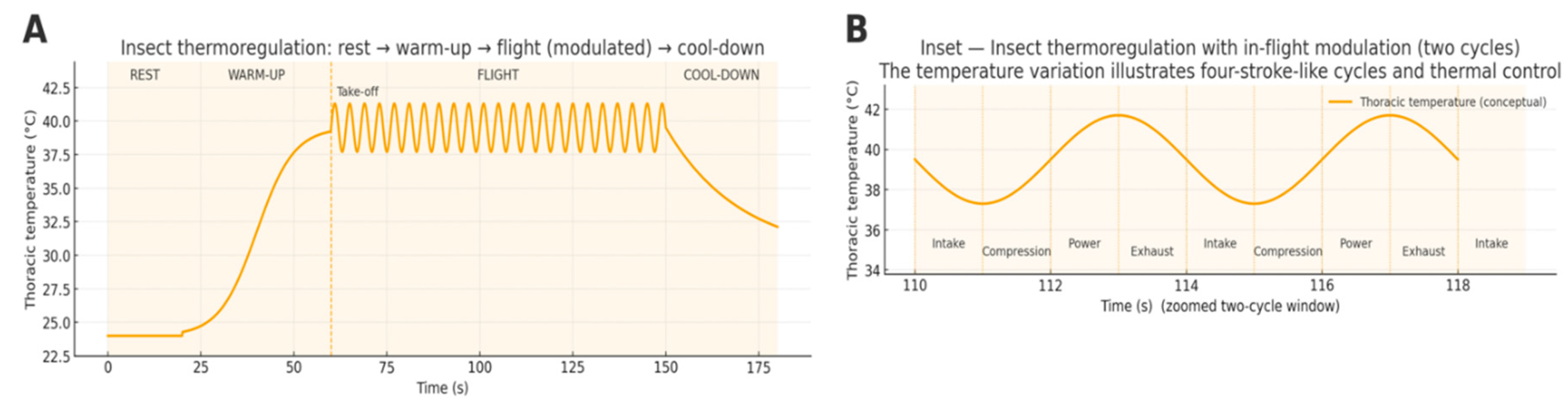
Figure 10.
Insect thermoregulation with in-flight modulation (A/B). (A) Full timeline from REST (cool) through WARM-UP (shivering) to FLIGHT, where a visible periodic modulation illustrates beat-synchronous thermal cycling (amplitude enlarged for clarity), followed by COOL-DOWN to repay thermal debt. (B) Zoom into two cycles, labeled Intake → Compression → Power → Exhaust to highlight the four-stroke-like modulation during steady flight. Real wingbeat oscillations occur at 10²–10³ Hz and are typically smaller; the schematic emphasizes the control concept supported by classic thermoregulation studies [21,22,23,24,32].
4.6. Miniturbines: Scaling Limits, High RPM, and Cold-Start Latency
Miniaturization hurts Brayton machines: higher relative tip-clearance and lower Reynolds degrade stage efficiency; non-adiabatic effects loom larger [38,39,40,41]. Even commercial ~30 kW microturbines (e.g., Capstone C30) reach only ~26% [42,43] electrical efficiency (LHV) in recuperated simple cycle, far below big turbomachinery [42,43]. To reclaim pressure ratio at small diameters, rotors spin very fast (often >120 krpm) [44,45], stressing bearings/rotors and complicating thermal transients [44,45]. Start sequences (purge → light-off → accel) impose ~15-20 s [46] cold-to-idle delays even for RC-scale microjets, unlike the insect’s instant re-engagement once warm.
Consequence: miniturbines show narrow efficiency peaks, seconds-scale startup, and rpm ceilings, demanding strict burst budgeting and explicit warm-up/cool-down policies.
4.7. Computational Governance: Engine ECUs vs. Insect Nervous Systems
Modern powertrains use ASIL-D MCUs delivering multi-billion-instructions/s (DMIPS) paired with hardware timing engines for sub-ms injector/ignition scheduling, e.g., Infineon AURIX TC39x (~2700 DMIPS; six 300 MHz cores) and NXP MPC5777C (dual 300 MHz + eTPU2 channels for precise pulse timing) [11,47,48,49].
Insects achieve comparable actuation rates with distributed, event-driven control: a modest descending channel gates thoracic CPGs, while asynchronous muscle and elastic thoraces supply high-frequency mechanics [32,33,34,35,50]. The whole-brain Drosophila connectome (~139k neurons, ~50+ M synapses) underscores a rich yet compact controller that remains compatible with low-power edge implementations [51].
4.8. Firmware Hooks: Operationalizing Natural Strategies for Timing, Thermal, and Safety Engineering
Physics-aware burst budgets. From Section 4.3, model the critical component temperature with
With initial , the solution is
The allowable burst duration is the first such that , i.e.,
After a burst, define thermal debt and remain in COOL-DOWN until ; Reflex loops stay live while Policy sheds first.
5. Use Cases and Actionable Guidance for Adoption
The insect-inspired architecture, latency-first, two-tier control with a Reflex Tier (near-sensor, kHz-rate, instant-on via MRAM/spintronic primitives) and a Policy Tier (slower planning/learning) plus the state-dependent thermal governance of Section 4, maps directly onto high-stakes systems that must act quickly, autonomously, and efficiently under tight energy and thermal limits. Below we convert the biology and physics into engineering recipes, with concrete components, control patterns, and validation steps.
The insect-inspired architecture characterized by its latency-first two-tier control, spintronic-enabled instant-on capability, and state-dependent governance translates directly into critical advantages for systems where real-time, autonomous, and energy-constrained operation is paramount. This section outlines key use cases and provides actionable guidance for the adoption of these principles.
5.1. Design of Novel Fuel-Based Propulsion Systems with High Thrust
(Make power by frequency—keep efficiency flat)
As established in Section 4.5–Section 4.6, ICEs and miniturbines are peak-island machines; insects achieve flat-band efficiency by frequency control + thermoregulation; therefore we decouple prime mover (held at its island) from propulsor (frequency-controlled).
5.1.1. Objective and Rationale
Conventional thermal engines (ICEs and miniturbines) exhibit narrow best-efficiency islands tied to a particular power–rpm; efficiency falls sharply away from that point (see Fig. 4.3; Section 4.5.3). Tuning injection pulse frequency and timing helps emissions and noise but does not flatten the fundamental efficiency map (Section 4.5.1–Section 4.5.3). Insects instead regulate power by actuation frequency while holding muscle efficiency nearly constant by keeping temperature at a set-point and scaling ventilation/evaporation with work (Section 4.2–Section 4.5).
Goal: build fuel-based propulsion that behaves like an insect at the system level, frequency-controlled thrust with near-constant efficiency over a wide range, by decoupling the prime mover from the propulsor and letting each live in its optimum regime.
5.1.2. Architecture Blueprint (“Frequency Governor” Hybrid)
- Prime mover (constant-efficiency island): a small ICE or miniturbine run near its best-efficiency point (narrow island; Section 4.5.3, Section 4.6).
- Electric buffer: battery + supercaps sized to absorb burst gaps between average and instantaneous power (Section 4.3 ODE + burst budgets).
- Propulsor (frequency-controlled): high-response electric motor + prop/fan/pump-jet; thrust tracks motor electrical frequency, keeping mechanical efficiency high across output range (insect analogue).
- Power electronics: bi-directional DC/DC + inverter; reflex-class PWM at kHz.
- Reflex Tier: MRAM-resident, instant-on controller executing stabilization and thrust commands at kHz (mirrors thoracic reflex loop).
- Policy Tier: slow planner (routing, mission, optimization), exporting only goal states.
- Thermal governance: the state machine from Section 4.2 enforces WARM-UP → WORK → BURST → COOL-DOWN with thermal-debt accounting from Section 4.3.
Why it works: the prime mover sits on its island almost all the time; thrust is modulated by motor frequency, just like wingbeat in Section 4.5.2. The buffer covers fast transients and manages the latency of thermal machines (Section 4.6: miniturbines’ cold-to-idle seconds).
5.1.3. Control Strategy (Reflex/Policy Split)
Reflex (kHz): Close thrust/torque and stabilization loops within 1–2 ms end-to-end. Enforce the thermal burst budget by integrating online and terminating BURST when reaches or when the closed-form limit is hit; log thermal debt and transition to COOL-DOWN while keeping Reflex deadlines met. Shed Policy first whenever thermal/voltage margins shrink.
Policy (10–100 ms+): Keep the prime mover on its iso-BSFC island with slow trims; plan missions and schedule WARM-UP before expected BURST windows.
5.1.4. Hardware Patterns by Domain
Road (range-extender)
- 20–60 kW ICE or microturbine @ island → 400–800 V DC link; 200–400 kWh battery+cap bank sized for bursts.
- Propulsor: axle motors with field-oriented control (FOC); thrust = torque request = frequency (electrical).
- Outcome: city stop-go handled by the buffer + frequency control (insect-like), engine sits at steady island → flat real-world efficiency.
Air (distributed electric propulsion / hybrid)
- 30–150 kW miniturbine-generator at island (cf. Section 4.6); high-rpm and start latency hidden by buffer.
- Multiple small props per wing; per-motor frequency sets local thrust, enabling gust rejection with Reflex kHz loops.
- Outcome: safe, responsive thrust modulation without throttling the turbine off-design.
Water (pump-jet / prop)
- Diesel-gen at island; pump-jet thrust from impeller frequency; cavitation avoided via Reflex watchdogs (pressure/accel).
- Outcome: smooth low-speed thrust with prime mover steady; excellent station-keeping.
5.1.5. Sizing & Math Hooks (Quick Rules)
Energy buffer. For a target burst window , size the buffer so that
at end-of-life conditions (hot, aged).
Thermal limit. Use Section 4.3 parameters to compute the allowable burst time
Thrust scaling reminder. For props/fans at similar efficiency and fixed geometry, thrust follows shaft frequency; regulate frequency (insect analogue) rather than throttling off-island.
5.1.6. Safety & Certification Hooks
The insect-style separation between fast Reflex and slower Policy provides explicit hooks for safety cases under ISO 26262, IEC 61508, or ISO 13849. For a given propulsion application we adopt:
- Freedom-from-interference (FFI). The Reflex Tier runs on a pinned core (or dedicated neuromorphic die) with fixed priorities, no dynamic memory, and one-way single-producer/single-consumer (SPSC) queues from Policy. All plant-stabilizing loops (thrust, torque, braking) close entirely inside this island. Policy cannot pre-empt or delay Reflex work; its influence is limited to low-rate goal states (e.g., speed corridors, thrust limits).
5.1.7. Validation Plan (Step-by-Step)
- HIL loop at kHz with plant models (prop, drivetrain, buffer, engine/turbine).
Burst tests: record
- vs. predicted Section 4.3 curve; verify deadlines and miss counters = 0.
- Thermal cycles: alternate BURST/COOL-DOWN to validate thermal-debt controller.
- Off-design trials: hold prime mover at island while sweeping thrust frequency; confirm flat system efficiency compared to stock throttle maps.
- Fault injection: sensor dropout, clock drift, memory CRC fault; verify Reflex containment.
5.1.8. Quick “Principle → Requirement → Action” Table5.1.9. Insect Inspired Fuel Based IFEVS Thruster
| Principle | Propulsion Requirement | Actionable Guidance |
| Frequency-controlled thrust (insect) | Wide-range thrust with minimal efficiency drift | Decouple: prime mover at island; thrust via motor frequency; buffer covers transients (Section 4.5–Section 4.6) |
| Thermal governance | Bounded temps during bursts | Apply Section 4.3 ODE to compute burst time; enforce COOL-DOWN; shed Policy first |
| Instant-on Reflex | kHz stabilization independent of prime-mover state | MRAM Reflex Island near drivers/sensors; deadline monitors; DMA windows |
| Cold-start latency (miniturbine) | Usable thrust before light-off | Pre-warm plan; buffer-only takeoff/launch; soft-hand-over to turbine (Section 4.6) |
| Safety case | WCET & FFI | Fixed priorities; single-core pinning; one-way SPSC queues; watchdogs & logs |
Building on the experience of the first author, who as former director of the Fiat Research Centre contributed to the development and industrialisation of the common-rail diesel injection concept, one of the key enablers in raising production diesel engine efficiencies from ~25% to >45%, we now seek an analogous step change in specific efficiency for small air-breathing thrusters. The IFEVS concept is in an advanced design and prototyping phase; the figures used here are engineering estimates informed by subsystem tests and 1D cycle analysis. A separate, dedicated propulsion paper is in preparation; the present section only needs enough fidelity to support the architectural argument of Section 5.1.
Data status, test conditions, and methodology
The quoted >40% thermal efficiency refers to fuel-to-jet power at the outlet of the hot core before the compact augmenter. This value is obtained from a cycle model calibrated against component-level measurements of combustor pressure loss and temperature rise, nozzle efficiency, and measured mass flow under ISA sea-level static conditions (ambient 15–20 °C, p ≈ 101 kPa, zero flight speed). The working fuel in all comparisons is Jet-A/kerosene with a lower heating value LHV ≈ 43 MJ/kg; we assume ±1 MJ/kg variation in LHV in the uncertainty budget.
The present prototypes are instrumented with conventional laboratory sensors (differential and absolute pressure transducers, K-type thermocouples, and fuel flowmeters), but a fully integrated, long-duration test rig with formal calibration traceability is still under construction. For this reason, we treat the IFEVS numbers here as design-point values with conservative uncertainty bands, rather than as final certified performance. We report thermal efficiency as 40% ±5 percentage points, reflecting model uncertainty, instrumentation accuracy, and sensitivity to assumed pressure losses.
Reference microturbine and comparison basis
To make the comparison concrete, we benchmark against a commercial ~400 N-class microturbine (JetCat-P400), using public thrust and fuel-flow data across its allowable throttle range. From these we derive 10 representative points between 80 N and 540 N equivalent thrust. At each point we compute the effective fuel consumption (mL/min) and an approximate overall thermal efficiency using the same Jet-A LHV and sea-level static assumptions.
On the IFEVS side, the cycle model provides core mass flow, temperature ratio, and jet power as a function of fuel flow, from which we derive thrust before and after the compact augmenter. This augmenter trades jet speed for entrained mass flow and static pressure recovery, yielding a thrust multiplication of 1.8 ±0.1 with only a modest additional pressure loss. The result is a nearly flat efficiency band from ~30 N to >600 N net thrust, in contrast to the narrow peak of the microturbine.
A summary comparison is given in Table 2, where for each thrust level we list:
- microturbine thrust and fuel flow,
- IFEVS thrust and fuel flow, and
- the resulting fuel-flow ratio IFEVS/microturbine.
Over the 400 N design point, the IFEVS thruster consumes ≈0.5 ±0.05 times the fuel of the reference microturbine. At low partial load (~80 N), where the turbine operates far off its BSFC island, the ratio drops to ≈0.37 ±0.05, consistent with the insect analogy of nearly constant muscle efficiency over a wide power range (Section 4.5.3).
In practice, the IFEVS thruster behaves like an internal combustion engine that never leaves its best-efficiency island: it reaches a typical ICE peak thermal efficiency (≈40%) but, insect-style, keeps this efficiency essentially flat across its whole operating thrust range, rather than collapsing at partial load as miniturbines do.
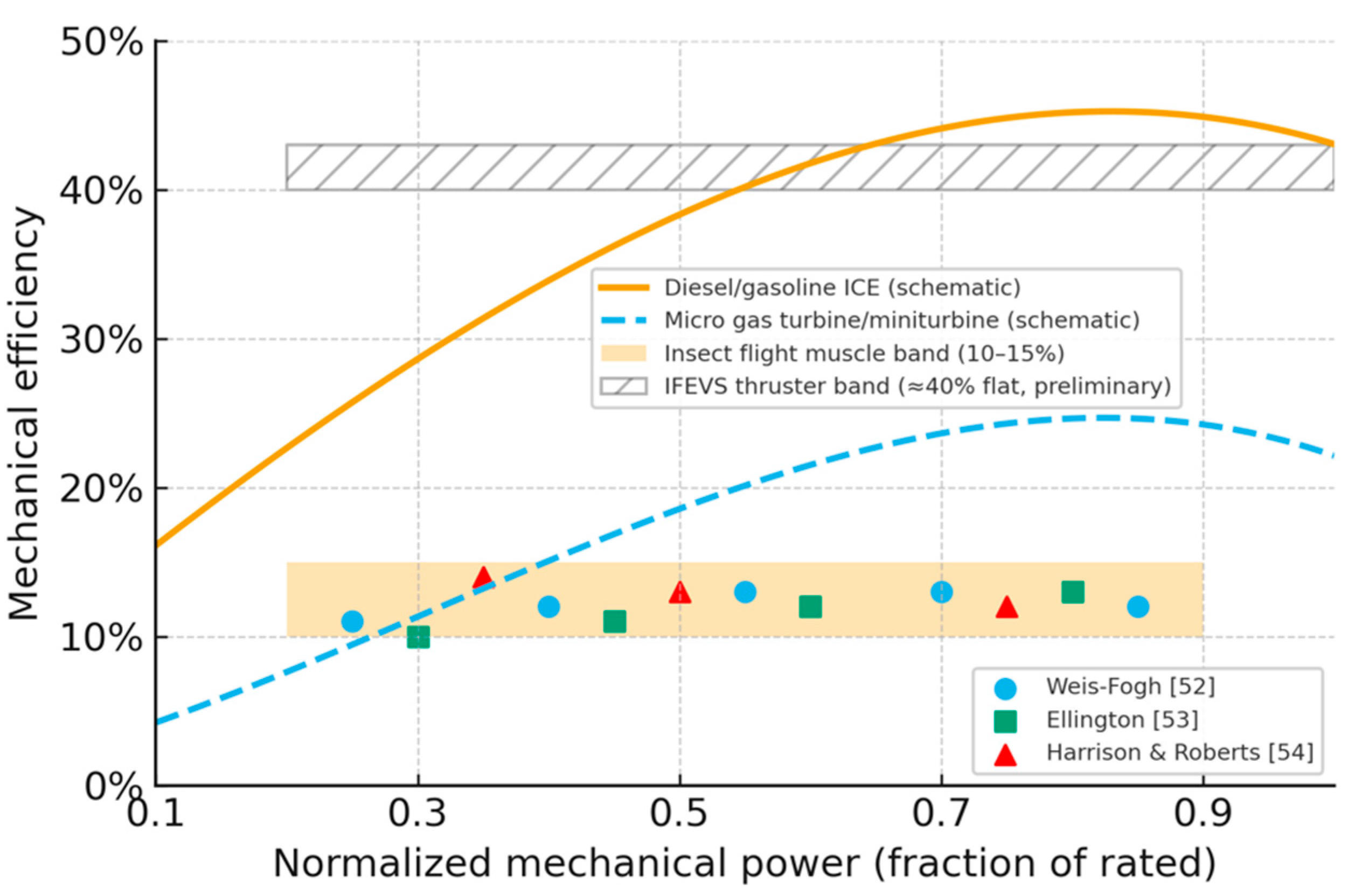
Figure 11.
Comparison of schematic mechanical efficiency envelopes for conventional engines, miniturbines, insect flight muscle, and the IFEVS thruster. Normalized mechanical power is expressed as a fraction of rated power. The solid curve shows a typical diesel/gasoline internal combustion engine with a narrow efficiency peak around 40–45%. The dashed curve shows a representative gas miniturbine (200N-400N) with a lower peak efficiency (~25%) and pronounced off-design penalties. The shaded band at 10–15% reproduces the insect flight muscle efficiency envelope, with representative digitized data points from Weis-Fogh [52], Ellington [53], and Harrison & Roberts [54]. The hatched band illustrates preliminary IFEVS thruster data (50N-600N), with a nearly flat thermal-mechanical efficiency slightly above 40% from ~0.2 to 1.0 of normalized thrust, combining ICE-like peak efficiency with insect-like flatness across load.
Uncertainties, limitations, and mission-level projections
- The uncertainties quoted above are engineering confidence intervals derived from:
- model sensitivity to assumed pressure losses and mixing efficiency (±3–4 percentage points on thermal efficiency),
- expected calibration accuracy of mass-flow and temperature sensors (±2–3%),
- variability in augmenter entrainment ratio and back-pressure (±0.05 on thrust multiplication), and
- variability in ambient conditions around the ISA reference (±5% in density over a 10–15 °C swing).
Combining these conservatively gives the ±5 percentage points band around the 40% thermal-efficiency figure and the ±0.05 bands on the fuel ratios quoted above. For acoustic predictions we similarly carry a ≤100 ±3 dB at 3 m estimate, based on subsonic ejector exit velocities and standard semi-empirical jet-noise models; full aeroacoustic measurements are part of the planned integrated test campaign.
At the system level we have also simulated simple mission profiles, hover, climb, and level cruise, using the same cycle model coupled to a notional vehicle mass and drag. These simulations show that, for representative duty cycles, the integrated fuel saving versus the microturbine remains in the 40–60% range, with the largest relative gains appearing at low-power segments (hover, loiter) where the turbine spends long periods far from its efficiency island. Because the mission simulations share the same model and assumptions as the static design points, we present them qualitatively and defer full time-series plots of thrust, fuel flow, exhaust gas temperature, and exhaust temperature to a dedicated technical report.
Architectural implications
- Even with these conservative uncertainties, the picture that emerges is robust:
- an insect-style prime mover whose efficiency degrades gently with load instead of collapsing away from a narrow island;
- instantaneous response (valve/ignition limited) rather than seconds-scale spool dynamics;
- cool, slow exhaust (~150 °C at the augmenter exit) enabling safe operation near people and structures; and
- a mechanically simple, non-rotating architecture naturally compatible with the Reflex/Policy split and WCET reasoning of Section 2 and Section 5.1.6.
The IFEVS thruster is a worked example of how insect-inspired thermodynamics and neuromorphic control can combine: a compact “thorax” running near its efficiency sweet spot, coupled to an ejector “wing” that shapes thrust without paying the usual penalties at partial load. A full validation and peer-review of the propulsion data will follow in a dedicated venue; here, the thruster serves to make the architectural trade-offs of the insect template concrete.

Table 3.
Comparison table of the Insect inspired fuel based Thruster vs State-of-the-art microturbine.
Table 3.
Comparison table of the Insect inspired fuel based Thruster vs State-of-the-art microturbine.
| Metric | IFEVS thruster | State-of-the-art microturbine (similar thrust) |
| Thermal efficiency (core) | > 40% before augmenter (fuel→jet power) | ~20–30% peak; sharp drop off-design |
| Thrust–load behaviour | Flat efficiency from ~30 N → 600+ N after augmenter | Narrow island; poor partial-load BSFC |
| Fuel use @ ~400 N | ≈ ½ the fuel of miniturbine | Baseline |
| Fuel use @ ~50 N | ≈ ⅓ the fuel vs turbine at low-load operation | Strong efficiency loss at low throttle |
| Exhaust temperature | ~150 °C at augmenter exit | ~500–1000 °C EGT; hot jet |
| Acoustic signature | ≤100 dB @ 3 m, subsonic ejector exit | Hot, often supersonic microjets; much louder |
| Response time | Near-instant; no spool-up | Spool-up / light-off delays (seconds) |
| Architecture / maintenance | No rotating parts; ~½ weight; low maintenance | High-speed rotor/bearings; higher maintenance load |
Notes: For aerial micro-robots, Section 5.1’s frequency-governed thrust (electric props) is directly applicable; for ground robots, use frequency-to-torque via FOC current loops with the same thermal budgeting logic.
Efficiency and fuel use. At the thermodynamic level the IFEVS core reaches >40% thermal efficiency before the compact augmenter, i.e., roughly double the typical 20–30% peaks reported for small recuperated microturbines (Section 4.6). Because thrust is boosted by an ejector-style augmenter that trades jet speed for entrained mass flow and static pressure recovery, the system maintains a near-flat efficiency band from ~30 N to >600 N net thrust. This directly mirrors the insect pattern of “power by frequency at nearly constant efficiency” (Section 4.5.3): thrust is modulated by flow and frequency, not by throttling the core far off its island. In practical terms, at a ~400 N design point the IFEVS thruster consumes roughly half the fuel of a miniturbine, and at ~50 N partial load the fuel burn can drop to about one-third of a turbine operating at the same net thrust but far from its optimum island.
Augmenter, exhaust temperature, and safety. The compact augmenter delivers an additional ~×1.8 thrust boost with minimal extra fuel by entraining ambient air and recovering static pressure, rather than simply accelerating a small hot jet. This produces a much cooler mixed exhaust, with gas temperatures ~150 °C at the outlet instead of the 500–1000 °C typical for microturbine exhaust. The resulting low-temperature, low-velocity jet greatly simplifies vectoring hardware, reduces thermal loading on nearby structures, and shrinks the IR signature, critical for operations close to personnel, sensitive payloads, or in contested environments. In the insect analogy, the hot “muscle” is kept compact while the effective “wing” is a much larger mass of cooler entrained air.
Noise, signature, and mission envelopes. Because the ejector exit remains subsonic and the jet is relatively cool, predicted acoustic levels are ≤100 dB at 3 m for representative layouts, dramatically below the harsh tonal noise produced by hot, sometimes choked microjets of similar thrust. Combined with the low exhaust temperature, this softens both acoustic and infrared signatures, enabling operations near ground troops, in urban canyons, or for covert ISR platforms where microturbine noise and plume would be unacceptable. The low-speed gases are also naturally compatible with distributed ejector arrays, enabling rotor-free VTOL matrices where lift comes from many small, cool jets rather than exposed high-tip-speed rotors.
Response time and Reflex compatibility. Microturbines suffer from cold-to-idle and spool-up latencies in the 10–20 s range (Section 4.6), forcing them to loiter at fuel-wasting idle whenever immediate thrust might be required. The IFEVS thruster, with no high-inertia rotating assembly, offers near-instant activation: thrust is gated primarily by fast valves and ignition rather than rotor acceleration. This matches the latency-first architecture of Section 2: a neuromorphic Reflex Tier can safely command rapid starts, hops, and burst thrust changes within the kHz sensor–actuator loop, without being constrained by seconds-scale turbomachinery transients. In other words, the effective cold-to-useful-thrust latency becomes compatible with insect-like bursts and with the burst-budgeting logic of Section 4.2–Section 4.3.
System simplicity, VTOL potential, and business appeal. Compared to a miniturbine, the IFEVS thruster is mechanically simple (no compressor or turbine stages, no high-speed bearings), exhibits higher intrinsic reliability, and is expected to weigh roughly half as much for the same thrust envelope. The cold, low-speed exhaust opens the door to closely packed, ducted thruster matrices for rotorless VTOL and agile attitude control, directly benefiting from the frequency-governed thrust patterns of Section 5.1. From an industrial standpoint, the architecture is compatible with automotive-style manufacturing (sheet-metal, castings, standard injectors), supports multiple fuels including future green drop-ins, and scales from small logistics drones to larger platforms. This combination of deep-tech novelty (spintronic-enabled Reflex control, insect-inspired thermodynamics) with a clear manufacturing and certification path is precisely the kind of defensible, low-risk innovation that can appeal even to conservative investors and defence procurement agencies.
5.2. Autonomous Vehicles & Micro-Robotics (A One-To-One Mapping of the Insect Edge)
| Principle | Vehicle Requirement | Actionable Guidance |
| Reflex Tier (Fly) | Deterministic safety: stabilization, obstacle avoidance, traction/braking | Co-locate IMU/event camera + Reflex Island; run stabilization at 1–2 kHz; keep E-stop <1 ms path; MRAM for instant-on |
| Policy Tier (Bee) | Robust navigation: VO, mapping, intent | Separate RT core/NPU at low priority; publish only goal states (speed corridors, waypoints) to Reflex |
| Thermal governance | Predictive performance: short high-power bursts | Implement Section 4.2 state machine; compute burst budgets via Section 4.3; log thermal debt and deadline misses |
| Spintronics | Low-power, event-driven perception | Use STNO reservoirs for vibration/flow/event-camera streams; MRAM synapses for reflex weights |
| Certification | Freedom-from-interference | Partition clocks/cores/memory; lock-free SPSC; WCET tables; watchdog + safety log |
Insect Inspired Vision for Safer Cargo E-Bikes
Urban cargo e-bikes operate in a cluttered, high-conflict environment: dooring, side-swipes by vans, pedestrians stepping out from occlusions, and sudden braking by leading vehicles. Following recent work on active vision and pattern recognition in bees [58], insect-inspired neuromorphic computing [59], and insect-brain-inspired policy learning [60], we treat the bike and rider as a “fly + bee” system on wheels: wide-field, low-latency vision for immediate collision avoidance (fly), combined with slower heuristics and route-level support (bee).
Concretely, we propose a multi-camera “vision belt” around the cargo e-bike frame (front, rear, lateral fisheye modules) plus IMU and wheel-speed sensors. Each camera/IMU pair feeds a near-sensor Reflex Tier on a neuromorphic/low-power SoC, running insect-like primitives: wide-field optic-flow estimation, looming/closing-speed detection, lane/door-zone detection, and basic vulnerable-road-user classification, echoing the spatiotemporal encoding strategies observed in bee lobula neurons [58]. The Reflex Tier must signal imminent collision risks within a strict latency envelope so that the rider’s braking and evasive actions remain effective.
Latency budget for the cargo e-bike Reflex loop
Table 4 summarizes a representative latency budget for one Reflex loop (front camera + IMU → looming SNN → haptic/LED cue). We assume a 200–250 Hz global-shutter CMOS or DVS camera, with events delivered to a Loihi- or Akida-class neuromorphic core and a simple microcontroller-based haptic/LED driver. The numbers are worst-case at the hot electrical corner (high temperature, low voltage) and include guard bands:
This yields an end-to-end Reflex latency of ≈18 ms against a 20 ms design target, leaving ~10% margin. Immediate emergency cues (hard looming, imminent lateral impact) are generated directly by the Reflex Tier and bypass the slower Policy Tier, which handles trajectory-level reasoning. Given that human reaction times are typically O(500 ms), this sub-20 ms envelope is sufficient to meaningfully extend the effective braking distance margin in urban traffic.
Energy budget and solar sizing
From a power perspective, the cargo e-bike behaves like a small ground “drone”: propulsion dominates the energy budget, but sensing/compute must remain compatible with a largely self-charging vehicle. Reviews of electric cargo cycles report energy consumption in the range of 9–18 Wh/km depending on load and terrain; we adopt 14 Wh/km as a conservative value for loaded last-mile delivery work. For a typical urban duty cycle of 40 km/day, the propulsion demand is then about 560 Wh/day.
The neuromorphic safety shell (multi-camera belt, IMU, Reflex Tier, haptics/LEDs, and a small Policy MCU) can be dimensioned to draw on the order of 5 W average while riding and ≲1 W in idle/parked monitoring, using near-sensor event cameras and low-power SNN hardware. For 3 h/day of active riding and 9 h/day of low-rate monitoring this corresponds to ≈30 Wh/day, small compared to propulsion but non-negligible in a solar-assisted system.
We therefore size a vehicle-integrated PV surface on the cargo box and canopy of A ≈ 1.0 m², consistent with existing solar e-bike and cargo-bike implementations (1.0–1.5 m² roofs or box faces). Assuming commercially available lightweight modules with η ≈ 23% [68] and a central south Europe latitude average insolation of ≈4.6 kWh/m²/day over the year on a horizontal surface the daily energy harvest is:
EPV≈A×η×H×f≈1.0 m2×0.23×4.6 kWh/m2/day×0.6≈0.63 kWh/day
where accounts for MPPT/charging efficiency and shadowing.
Compared to the ~0.63 kWh/day of total demand (0.60 kWh propulsion + 0.03 kWh sensing/compute), the PV system covers most km in a typical European summer/spring duty cycle, leaving a modest margin for less favourable conditions. This order-of-magnitude balance is consistent with recent measurements on solar electric cargo bikes developed by IFEVS withing the Edge AI Trust project [69], whose ~210 Wp of integrated PV supply roughly 50% on average and up to 100% of the daily energy consumption in last-mile delivery operations of a 1000L box cargo bike (full dataset available in forthcoming project report).
Integration with the insect template
The resulting architecture is directly compatible with the insect template of this paper:
- a fast Reflex Tier (camera/IMU → neuromorphic looming SNN → haptic/LED) with a quantified sub-20 ms WCET envelope and clear separation from the slower route-planning Policy Tier;
- a solar-governed duty cycle where the bike operates much like an insect balancing energy intake and expenditure over the day; and
- a largely self-charging cargo platform analogous to existing IFEVS-type systems, but with an explicit safety-critical perception shell inspired by insect vision.
5.3. Medical implants and wearable devices (Years of standby; milliseconds to act)
| Principle | Medical Requirement | Actionable Guidance |
| DGC / I/O gating (Section 4.1) | Extreme energy conservation | Closed/Flutter duty-cycling of sensing; Open on anomaly; RTC-only heartbeat during Closed |
| Spintronics (MRAM) | Instant event capture & integrity | Reflex Tier always resident in MRAM; no DRAM warm-up; log ring-buffers with ECC/CRC |
| Policy learning | Personalized thresholds | On-device adaptation (simple STDP/EMA) in Policy; export only gains/thresholds to Reflex |
| Thermal governance | Skin comfort & safety | Treat surface and battery with Section 4.2 state machine; guarantee Reflex availability while throttling analytics |
| Safety & privacy | Determinism & local data | WCET envelopes for detection; encrypted logs; on-device inference; no cloud dependency for immediate actions |
Examples: seizure detectors, arrhythmia monitors, closed-loop neurostim; the Reflex executes detection/stim in sub-ms; Policy adapts over days; thermal protects tissue.
5.4. Industrial robotics & control (Uptime and determinism above all)
| Principle | Industrial Requirement | Actionable Guidance |
| Reflex isolation | Immediate safety (E-stop, limits, interlocks) | Put all safety loops on Reflex Island; pin core, fixed priorities; zero dynamic memory; deadline monitors |
| Two-tier split | Flexible tasks w/o jitter | Reflex: 1–2 kHz PID/LQR, commutators; Policy: vision, optimization, job scheduling; one-way queues |
| STNO reservoirs | High-bandwidth sensing | Inline temporal processing for accelerometers/vibration; predictive maintenance at the edge |
| Thermal governance | Shift-resilience | Use Section 4.3 budgets; enforce COOL-DOWN; rate-limit bursts; log thermals for maintenance |
| Certification | SIL 2–3 / ISO 13849 | Prove freedom-from-interference; margin ≥30% on Reflex deadlines at hot corner; watchdog and safe states documented |
To achieve safety certification (e.g., ISO 26262/ASIL), the Reflex Tier must be proven deterministic under error; this requires deploying Fault-Testing Strategies, specifically transient fault injection targeting the spintronic primitives (MRAM/STNO stochasticity) and Policy/Reflex boundary violation testing to quantitatively demonstrate that failure modes in the Policy Tier cannot compromise the Reflex Tier's integrity, ensuring the system can either gracefully degrade to a safe state or initiate an emergency stop within the prescribed tau < 1 ms safety window.
6. Conclusions
We have argued that insects offer a compact but powerful blueprint for edge intelligence: a fast, latency-bounded Reflex Tier co-located with sensors and actuators, and a slower Policy Tier that reasons over maps, goals and long timescales. On the hardware side, we showed how spintronic primitives (MRAM synapses and STNO “neurons”) can implement this hierarchy with predictable worst-case execution times, extremely low standby power and innate robustness to noise. On the system side, we instantiated this template in two domains: an insect-inspired IFEVS thruster with nearly flat-band efficiency, and a 360° vision shell for solar cargo e-bikes. In both cases, the insect metaphor is not decorative, but structural: power is modulated primarily by frequency, thermal debt is carefully governed, and reflexes are strictly separated from higher-level policy.
From an environmental standpoint, the architecture is deliberately biased towards doing more with less. The IFEVS thruster operates at higher thermal efficiency than reference miniturbines across a wide load range, roughly halving fuel consumption around its 400 N design point and gaining even more at partial load. That translates directly into reduced CO₂ emissions and lower local pollutants for a given mission profile, particularly in duty cycles dominated by loiter, hover or low-power cruise. The cargo e-bike example pushes the same logic to the urban ground scale: a safety-critical neuromorphic shell that typically consumes only tens of Wh per day and can be powered, together with propulsion, by a modest square metre of high-efficiency PV. Combined with near-sensor computing and spintronics, this suggests a path to energy-autonomous edge systems that lean on local renewables instead of continuous grid or cloud backhaul.
The social and ethical implications are equally important. Both application examples target safety in human environments: quieter, cooler thrusters that can operate near people and infrastructure without dangerous exhaust plumes, and cargo cycles that watch for dooring, side-swipes and vulnerable road users. At the same time, the same sensing and control capabilities are intrinsically dual-use: the architecture that makes a delivery bike safer also makes a small drone more capable in contested space. It is therefore crucial that insect-inspired edge AI be developed under explicit governance and transparency constraints: clear separation between safety reflexes and mission logic; documented WCET envelopes and fault-containment behaviour; and strict data-minimisation for vision systems in public space (e.g., optic-flow and looming detection without long-term identity tracking). The insect blueprint helps here as well: minimal memory, task-specific perception, and short retention by design.
There are, however, limits and risks on the hardware side, especially for spintronics. While embedded MRAM is already at high technology readiness and can be exploited as a non-volatile synaptic substrate, large-scale STNO reservoirs and dense spin-neuron fabrics are still maturing. Process variability, thermal noise, coupling complexity and integration with CMOS place practical bounds on the size and precision of neuromorphic networks one can implement in the near term. Materials and supply-chain constraints (e.g., reliance on specific alloys or fabrication steps) may also cap scalability or concentrate manufacturing in a small number of fabs, which raises resilience and sovereignty questions. There is a risk of over-promising if spintronics is treated as a drop-in replacement for all forms of AI acceleration rather than as a targeted solution for ultra-low-power, reflex-like tasks.
More broadly, the insect template comes with architectural risks if misapplied. A reflex-dominated system without sufficient transparency can be difficult to audit or override; conversely, an overgrown Policy Tier that continuously interferes with Reflex loops undermines the very determinism the architecture is meant to guarantee. In this sense, the main limitation is not only technological but organisational: certification regimes, development processes and human-machine interfaces must keep the Reflex/Policy boundary clean, explainable and testable. Our proposed WCET envelopes, fault taxonomies and fault-injection campaigns are first steps, not final answers.
Despite these caveats, we believe that “edge AI in nature” is more than a metaphor: it is a design discipline. Insects show that it is possible to combine strict energy budgets, hard real-time reflexes and surprisingly rich behaviour in tiny, noisy packages. Translating that discipline into spintronic-enabled electronics, fuel-efficient thrusters and solar-assisted micromobility will require sustained work across biology, materials science, safety engineering and policy. If done carefully, the payoff is compelling: edge systems that are not only more capable, but also more frugal, quieter, safer and easier to certify; in short, machines that borrow not just the agility of insects, but also their coexistence with the environments and societies they inhabit.
Acknowledgments
Supported by EIC Pathfinder MultiSpin.AI, grant no. 101130046, by HORIZON-JU-Chips-2025-1-IA NeAIxt grant no. 101194172 and by HORIZON-JU-Chips-2023-1-IA EdgeAI-Trust grant no. 101139892.
References
- Chan, W.-P.; Prete, F.; Dickinson, M. H. Visual input to the efferent control of wing steering in Drosophila. Nature 396 (1998) 460–464.
- Dickinson, M. H. Halteres in Diptera: the gyroscope of the insect world. Phil. Trans. R. Soc. B 354 (1999) 903–911.
- Egelhaaf, M.; Kern, R.; Juusola, M. Optic-flow based spatial vision in insects. J. Comp. Physiol. A 209 (2023) 487–502.
- Palka, J.; et al. The giant fiber pathway of Drosophila. J. Neurogen. 3 (1986) 1–14.
- Dickerson, B. H.; et al. A fly’s view of the world. Curr. Opin. Neurobiol. 54 (2019) 112–119.
- Baird, E.; Srinivasan, M.V.; Zhang, S.; Cowling, A. Visual control of flight speed in honeybees. J. Exp. Biol. 2005, 208, 3895–3905. [Google Scholar] [CrossRef] [PubMed]
- De Marco, R. J.; Menzel, R. Encoding spatial information in the waggle dance. J. Exp. Biol. 208 (2005) 3885–3894. [CrossRef] [PubMed]
- Kim, S.S.; Rouault, H.; Druckmann, S.; Jayaraman, V. Ring attractor dynamics in the Drosophila central brain. Science 2017, 356, 849–853. [Google Scholar] [CrossRef] [PubMed]
- Hulse, B. K.; et al. A neural circuit for an internal compass in Drosophila. eLife 10 (2021) e66039.
- Grollier, J.; Querlioz, D.; Camsari, K.Y.; Everschor-Sitte, K.; Fukami, S.; Stiles, M.D. Neuromorphic spintronics. Nat. Electron. 2020, 3, 360–370. [Google Scholar] [CrossRef]
- Infineon Technologies. AURIX™ TC39x Product Brief (2019): up to ~2700 DMIPS; ASIL-D.
- Schuman, C. D.; et al. A survey of neuromorphic computing and applications. Appl. Phys. Rev. 9 (2022) 011307.
- Davies, M.; Srinivasa, N.; Lin, T.-H.; Chinya, G.; Cao, Y.; Choday, S.H.; Dimou, G.; Joshi, P.; Imam, N.; Jain, S.; et al. Loihi: A Neuromorphic Manycore Processor with On-Chip Learning. IEEE Micro 2018, 38, 82–99. [Google Scholar] [CrossRef]
- Indiveri, G.; et al. Neuromorphic vision sensors and processors. Proc. IEEE 99 (2011) 1524–1548.
- Chen, B.-J.; et al. Spintronic devices for in-memory and neuromorphic computing—A review. Materials Today 70 (2023) 193–217.
- Marrows, C. H.; et al. Neuromorphic computing with spintronics. Nat. Rev. Phys. 6 (2024) 1–15.
- Lighton, J. R. B. Discontinuous gas exchange in insects. Annu. Rev. Entomol. 41 (1996) 309–324.
- Chown, S. L.; et al. Discontinuous gas exchange: consensus view. J. Exp. Biol. 209 (2006) 3719–3725.
- Hetz, S.K.; Bradley, T.J. Insects breathe discontinuously to avoid oxygen toxicity. Nature 2005, 433, 516–519. [Google Scholar] [CrossRef]
- Chown, S.L. Discontinuous gas exchange: new perspectives on evolutionary origins and ecological implications. Funct. Ecol. 2011, 25, 1163–1168. [Google Scholar] [CrossRef]
- Heinrich, B. Keeping a Cool Head: Honeybee Thermoregulation. Science 1979, 205, 1269–1271. [Google Scholar] [CrossRef] [PubMed]
- Heinrich, B. The Hot-Blooded Insects. Springer, 1993.
- Stabentheiner, A.; Kovac, H.; Brodschneider, R. Honeybee Colony Thermoregulation – Regulatory Mechanisms and Contribution of Individuals in Dependence on Age, Location and Thermal Stress. PLOS ONE 2010, 5, e8967–e8967. [Google Scholar] [CrossRef]
- May, M. L. Thermoregulation in insects. Annu. Rev. Entomol. 36 (1991) 155–184.
- Incropera, F. P.; et al. Fundamentals of Heat and Mass Transfer (8th ed.). Wiley, 2017.
- NIST CODATA. Stefan–Boltzmann constant 5.670374419×10^(-8)W·m⁻²·K⁻⁴.
- Bosch Mobility. Modular common-rail systems: up to 8 injections per cycle. Tech note (accessed 2025).
- Postrioti, L.; et al. Zeuch method-based injection rate analysis of a CR system. Fuel 130 (2014) 38–49.
- Costa, M.; et al. Split injection in homogeneous-stratified GDI. Energy 109 (2016) 608–620.
- Ferrari, A.; et al. Response of injector typologies to dwell-time variation. Appl. Energy 169 (2016) 899–911.
- Ferrari, A.; et al. Impact of common-rail systems on diesel engines. Energies 18 (2025) 5259.
- Altshuler, D. L.; et al. High-frequency wing strokes in honeybee flight. PNAS 102 (2005) 18213–18218.
- Hedrick, T. L.; Miller, L.; Combes, S. A. Recent developments in insect flight. Can. J. Zool. 93 (2015) 925–943.
- Pringle, J. W. S. Insect Flight. Cambridge Univ. Press.
- Syme, D.A.; Josephson, R.K. How to Build Fast Muscles: Synchronous and Asynchronous Designs. Integr. Comp. Biol. 2002, 42, 762–770. [Google Scholar] [CrossRef]
- Heywood, J. B. Internal Combustion Engine Fundamentals (2nd ed.). McGraw-Hill, 2018.
- Stone, R. Introduction to Internal Combustion Engines (4th ed.). Palgrave, 2012.
- Tran, B. N.; et al. Tip-clearance vs turbine performance. Energies 13 (2020) 4055.
- Xiang, J.; et al. Tip-clearance flow in miniature compressors. Int. J. Therm. Sci. 140 (2019) 123–133.
- Yamada, K.; et al. Low-Re effects in small turbomachinery. J. Turbomach. 141 (2019) 111004.
- AIP Advances: Tip-clearance & pre-stall features. 13 (2023) 115108.
- Capstone Turbine Corp. C30 Microturbine Data Sheet (NG): ≈26% LHV.
- Pure World Energy. Capstone C30 (30 kW): heat rate ≈13.8 MJ/kWh (26% LHV).
- Barnard Microsystems (UAV Engines). Typical rotor ranges: 35k–120k rpm (accessed 2025).
- Garrett/Turbo technical notes. High-speed micro-turbocharger dynamics (accessed 2025).
- JetCat. P250-PRO-S Turbojet: 13–20 s start-to-idle (2019).
- NXP. MPC5777C engine-control MCU: dual 300 MHz + eTPU2 (96 ch), eMIOS (32 ch).
- Renesas. VC4 domain controller: A55 + RH850, tens of kDMIPS (accessed 2025).
- ISO 26262. Road vehicles, Functional safety. 2018.
- Goodman, D.; et al. Descending neurons in Drosophila control behavior. Curr. Biol. 30 (2020) R928–R934.
- Lin, A.; Yang, R.; Dorkenwald, S.; Matsliah, A.; Sterling, A.R.; Schlegel, P.; Yu, S.-C.; McKellar, C.E.; Costa, M.; Eichler, K.; et al. Network statistics of the whole-brain connectome of Drosophila. Nature 2024, 634, 153–165. [Google Scholar] [CrossRef]
- Weis-Fogh, T. Energetics of Hovering Flight in Hummingbirds and in Drosophila. J. Exp. Biol. 1972, 56, 79–104. [Google Scholar] [CrossRef]
- Ellington, C.P. Power and efficiency of insect flight muscle. J. Exp. Biol. 1985, 115, 293–304. [Google Scholar] [CrossRef]
- Harrison, J.F.; Roberts, S.P. Flight Respiration and Energetics. Annu. Rev. Physiol. 2000, 62, 179–205. [Google Scholar] [CrossRef] [PubMed]
- Davies, M.; Srinivasa, N.; Lin, T.-H.; Chinya, G.; Cao, Y.; Choday, S.H.; Dimou, G.; Joshi, P.; Imam, N.; Jain, S.; et al. Loihi: A Neuromorphic Manycore Processor with On-Chip Learning. IEEE Micro 2018, 38, 82–99. [Google Scholar] [CrossRef]
- Grollier, J.; Querlioz, D.; Camsari, K.Y.; Everschor-Sitte, K.; Fukami, S.; Stiles, M.D. Neuromorphic spintronics. Nat. Electron. 2020, 3, 360–370. [Google Scholar] [CrossRef]
- Leveson, N. A new accident model for engineering safer systems. Saf. Sci. 2004, 42, 237–270. [Google Scholar] [CrossRef]
- MaBouDi, H.; Roper, M.; Guiraud, M.-G.; Juusola, M.; Chittka, L.; Marshall, J.A. A neuromorphic model of active vision shows how spatiotemporal encoding in lobula neurons can aid pattern recognition in bees. eLife 2025, 14. [Google Scholar] [CrossRef] [PubMed]
- Dalgaty, T.; Vianello, E.; De Salvo, B.; Casas, J. Insect-inspired neuromorphic computing. Curr. Opin. Insect Sci. 2018, 30, 59–66. [Google Scholar] [CrossRef] [PubMed]
- Yanguas-Gil, A.; Madireddy, S. General policy mapping: online continual reinforcement learning inspired on the insect brain. NeurIPS 2022 Workshop on Offline Reinforcement Learning, OpenReview (2022). https://openreview.net/forum?
- Lin, Z.; Hao, Q.; Zhao, B.; Hu, M.; Pei, G. Performance analysis of solar electric bikes. Transp. Res. Part D: Transp. Environ. 2024, 132. [Google Scholar] [CrossRef]
- Furber, S.; Bogdan, P. (Eds.) . SpiNNaker: A Spiking Neural Network Architecture. Now Publishers, Hanover, MA, 2020. (Monograph describing the Manchester SpiNNaker neuromorphic platform and its large-scale deployments.
- Akopyan, F.; Sawada, J.; Cassidy, A.; Alvarez-Icaza, R.; Arthur, J.; Merolla, P.; Imam, N.; Nakamura, Y.; Datta, P.; Nam, G.-J.; et al. TrueNorth: Design and Tool Flow of a 65 mW 1 Million Neuron Programmable Neurosynaptic Chip. IEEE Trans. Comput. Des. Integr. Circuits Syst. 2015, 34, 1537–1557. [Google Scholar] [CrossRef]
- BrainChip Holdings Ltd. BrainChip Akida neuromorphic processor and MetaTF development environment. Company technical overview and product pages, accessed 2025. (Describes the AKD1000 neuromorphic SoC used in commercial edge-AI kits.
- Christensen, D.V.; Dittmann, R.; Linares-Barranco, B.; Sebastian, A.; Le Gallo, M.; Redaelli, A.; Slesazeck, S.; Mikolajick, T.; Spiga, S.; Menzel, S.; et al. 2022 roadmap on neuromorphic computing and engineering. Neuromorphic Comput. Eng. 2022, 2, 022501. [Google Scholar] [CrossRef]
- IEEE International Roadmap for Devices and Systems (IRDS). Emerging Research Devices / Beyond CMOS Chapter, IRDS 2020 Edition, IEEE, 2020. Available at irds.ieee.org.
- Semiconductor Research Corporation; Semiconductor Industry Association. Decadal Plan for Semiconductors. Full report, 2021. (Defines research priorities including spintronic memories and beyond-CMOS logic for energy-efficient computing.
- www.solbian.
- https://www.edgeai-trust.
- Josephson, R. K. (1985). The mechanical power output of insect flight muscle. Annual Review of Physiology, 47(1), 543-563. [CrossRef]
- Niewiarowski, P.H.; Balk, M.L.; Londraville, R.L. Phenotypic Effects of Leptin in an Ectotherm: A New Tool to Study the Evolution of Life Histories and Endothermy? J. Exp. Biol. 2000, 203, 295–300. [Google Scholar] [CrossRef] [PubMed]
Table 1.
Example Reflex-loop WCET breakdown (optic flow + IMU → steering PWM).
| Stage | Function (example stack) | WCET (µs) | Cumulative (µs) |
| 1 | DVS/IMU exposure → interrupt assertion | 50 | 50 |
| 2 | DMA + time-stamp + spike encoding into Reflex Island | 150 | 200 |
| 3 | FF-SNN layer 1 (elementary motion detectors) | 800 | 1,000 |
| 4 | STNO reservoir / RSNN update + readout | 1,200 | 2,200 |
| 5 | Reflex decision logic + watchdog comparators | 400 | 2,600 |
| 6 | RT core arbitration, FOC current reference update | 400 | 3,000 |
| 7 | PWM/timer update + gate-driver propagation | 400 | 3,400 |
Table 2.
IFEVS vs JetCat P400 fuel flow vs net thrust (ISA SL, Jet-A).
| Thrust (N) | IFEVS fuel (mL/min) | P400 fuel (mL/min) | Fuel ratio IFEVS / P400 |
| 80 | 143 | 391 | 0.37 |
| 120 | 215 | 507 | 0.42 |
| 160 | 287 | 623 | 0.46 |
| 200 | 358 | 739 | 0.48 |
| 240 | 430 | 855 | 0.50 |
| 280 | 502 | 971 | 0.52 |
| 320 | 573 | 1087 | 0.53 |
| 360 | 645 | 1203 | 0.54 |
| 400 | 717 | 1319 | 0.54 |
| 440 | 788 | — | — |
| 480 | 860 | — | — |
| 520 | 932 | — | — |
| 540 | 968 | — | — |
Table 4.
Example Reflex-loop latency budget (cargo e-bike, front looming detection).
| Stage | Function | Latency (ms) | Cumulative (ms) |
| 1 | Camera exposure + readout / event aggregation | 5 | 5 |
| 2 | DMA + timestamp + spike/event encoding into Reflex Island | 2 | 7 |
| 3 | Looming-detection SNN inference (1–2 layers, few k neurons) | 4 | 11 |
| 4 | Reflex decision logic + hazard classification + queue write | 3 | 14 |
| 5 | Haptic/LED driver update + actuator rise time | 4 | 18 |
Disclaimer/Publisher’s Note: The statements, opinions and data contained in all publications are solely those of the individual author(s) and contributor(s) and not of MDPI and/or the editor(s). MDPI and/or the editor(s) disclaim responsibility for any injury to people or property resulting from any ideas, methods, instructions or products referred to in the content. |
© 2025 by the authors. Licensee MDPI, Basel, Switzerland. This article is an open access article distributed under the terms and conditions of the Creative Commons Attribution (CC BY) license (http://creativecommons.org/licenses/by/4.0/).
Copyright: This open access article is published under a Creative Commons CC BY 4.0 license, which permit the free download, distribution, and reuse, provided that the author and preprint are cited in any reuse.


