Submitted:
30 September 2025
Posted:
30 September 2025
You are already at the latest version
Abstract
To address the adaptability limitations of passive suspension systems in railway vehicles, this study investigates active control technology for dampers using a locomotive's vertical suspension as the research object. A six-degree-of-freedom vertical dynamics model was established as the recognition framework for the Model Predictive Control (MPC) algorithm. Based on this model, a prediction model was developed, and an objective function was designed with vehicle dynamics response as the constraint to complete the MPC controller design. A joint simulation model integrating the locomotive dynamics model and the MPC controller was constructed in MATLAB, adopting a parallel configuration of active and passive vertical dampers in the pendant suspension scheme.Comparative analysis through joint simulation demonstrated the superiority of active control over passive control in ride comfort. At 60 km/h, the MPC-based active damper control reduced the Sperling stability index by 11.21%, while the peak and RMS values of carbody settlement acceleration decreased by 24.9% and 28.7%, respectively. At 160 km/h, the corresponding reductions reached 32.5% (peak) and 31% (RMS) for settlement acceleration, with a 16.10% improvement in the Sperling stability index. These results validate the effectiveness of MPC-based active control in suppressing vertical vibration and enhancing railway vehicle ride quality.
Keywords:
primary vertical damper
; active control
; model predictive control
; running stability
1. Introduction
In the early 21st century, China's railway network has witnessed unprecedented expansion. By the end of 2023, the national railway operating mileage reached 162,100 km, including 48,000 km of high-speed rail (HSR) - the world's largest HSR network [1]. However, this rapid development has introduced significant challenges in maintaining operational safety and efficiency. Conventional passive suspension systems with fixed parameters struggle to adapt to dynamic operating conditions, necessitating temporary measures such as wheel retreading cycles, rail grinding, damper replacement, and speed reductions. These measures not only increase operational costs but also accelerate component wear, compromising long-term service life [2,3,4].
To address these limitations, researchers have explored semi-active and active suspension technologies. The Japanese National Railways (JNR) demonstrated that pneumatic actuators in transverse active suspensions could reduce lateral vibrations by approximately 50% at 120 km/h without compromising safety [5]. French researchers evaluated a fully active suspension system with electromechanical actuators and LQ control on a test bed, showing significant reduction in perceived vibration frequency [5]. Bruni et al. [6] applied LQG control to a vehicle model considering carbody flexibility and bogie pitch coupling, achieving notable ride comfort improvements across 150-350 km/h.
Domestic research has also made significant progress. Zeng Jing from Southwest Jiaotong University [7] developed an H∞ controller for active suspensions, validated through real-vehicle tests that confirmed improved operational smoothness while maintaining driving stability. Jin et al. [9] proposed a magnetorheological damper-based semi-active system for high-speed trains, demonstrating reduced vibration energy and enhanced stability. Hua et al. [10] simulated LQR control strategies using a 17-degree-of-freedom vehicle model under various operating conditions, while Rao et al. [11] optimized suspension parameters using linear quadratic regulators in semi-car models.
Recent advancements include Desai et al.'s [12] investigation of double-tube magnetorheological dampers in semi-active suspensions, Ripamonti and Chiarabaglio's [13] hardware-in-the-loop validation of semi-active shock absorbers with three control strategies, and Jin et al.'s [14] development of novel semi-active dampers with variable stiffness/damping characteristics. Wang et al. [15] analyzed LQR control weighting coefficients in a vertical coupling vibration model, achieving up to 50% reduction in carbody vibration RMS values. Shi et al. [16] proposed a sliding mode control scheme with disturbance observers, though requiring high-frequency actuators, while Gialleonardo et al. [17] integrated active lateral/tilt control using hydraulic actuators.
Notably, predictive control algorithms have emerged as promising solutions. Combining optimal control and process control principles [21], model predictive control (MPC) offers superior system regulation and stability compared to conventional methods [22]. However, existing suspension control algorithms often lack robustness against nonlinearities, time-varying parameters, and modeling errors.
This paper addresses these challenges by developing an MPC-based active control system for locomotive pitch dampers. A novel six-degree-of-freedom vertical dynamics model is established to serve as the recognition framework for the MPC algorithm, integrated with equivalent parameter models of pitch dampers. Through joint simulation validation, the proposed optimal cooperative control strategy demonstrates significant improvements in train operational smoothness, particularly in reducing Sperling index values and carbody acceleration metrics.
2. Vehicle Vertical Dynamics Model
To study the active control of train suspension systems, it is essential to establish both a train dynamics model and a damper model. REN et al. [23] developed a railway vehicle dynamics model using SIMPACK software to investigate the vertical acceleration of the car body. This chapter presents three key models: (1) a specific type of locomotive dynamics model, (2) an equivalent model of the pendant damper system, and (3) a 6-degree-of-freedom pendant dynamics model. The pendant damper equivalent model is integrated into the locomotive dynamics model for coupled simulation analysis, while the 6-degree-of-freedom pendant dynamics model functions as the identification model for the controller.
2.1. Vehicle Dynamics Modeling
This paper establishes a locomotive dynamics model using the SIMPACK software package [24,25]. To ensure model accuracy and computational efficiency, a systematic analysis of the model's topological structure is essential. Understanding the topological relationships between components clarifies their interconnections and relative motion characteristics. The locomotive dynamics model topology developed herein is presented in Figure 1.
The vehicle body is composed of four traction motors, two frames, four hollow axles, four wheelsets, four pairs of motor booms, two traction rods, and other suspension components. The two-stage suspension system between the vehicle body and frame combines: 1) Pendant dampers (2 units symmetrically distributed on both bogie sides) and anti-snake dampers (2 units asymmetrically mounted on bogie side beams), working with two sets of high-coil springs per side; 2) Transverse dampers (2 units symmetrically installed at frame ends). The primary suspension connecting wheelsets to the frame consists of axlebox tie rods, four sets of coil springs, and four pendant dampers. The lateral stop between car body and frame limits lateral movement to ensure safe operation. Since motor suspension adopts frame-mounted configuration, it requires simultaneous installation of motor brackets (2 units) and motor booms (2 units). Based on this configuration, the dynamics model contains 37 rigid bodies with 86 degrees of freedom.
2.2. Equivalent Parameter Modeling of a Pendant Damper System
Three comparable combinations of additional stiffness spring, nodal stiffness spring, and structural damping can be used to simplify the traditional one-series pendant hydraulic damper [26]. When designing an active control system based on a train's one-series pendant damper, here the one-series pendant damper acts as an actuator, and the controller calculates the optimal damping required for train operation through a control algorithm, and sends out control commands to change the damping coefficients of the damper in real time, so as to achieve real-time change of the control force to suppress the train's pendant impact, thus improving the vehicle's pendant smoothness.
Assuming that the mass of the piston is m and its displacement is preset to be yk, when the end of the piston rod is subjected to a sinusoidal excitation y=Asin(x) with amplitude A and frequency w, the mathematical expression of the equivalent parametric model at this point is:
The mathematical expression for the corresponding parametric model simplifies to the following form when the inertial force term is neglected due to the piston's relatively small mass:
2.3. Modeling of 6-Degree-of-Freedom Vertical Dynamics
Due to multidirectional vibration interference, it is difficult to fully replicate every detail of real-world operating conditions when a vehicle traverses a rail line. Consequently, the recognition model need only adequately describe the vehicle's dynamic behavior, allowing appropriate simplification [13]. Moreover, the complexity of the vehicle identification model correlates positively with controller design difficulty, while the accuracy of the developed controller improves when using the simplified model.
Based on prior analytical assumptions, the model accounts exclusively for the front/rear bogies and the car body's vertical (floating) and pitching (nodding) motions induced by track irregularities. Equations (3)-(8) present the differential equations derived from the 6-degree-of-freedom pendulum dynamics model:
(1)Equations (3) and (4) specifically describe the differential equations governing the car body's coupled floating and nodding motions, representing two degrees of freedom in the system.
(2)Equations (5) through (8) present the differential equations governing the vertical motion of the front and rear bogies, encompassing both floating and nodding motions and accounting for a total of four degrees of freedom in the system.
(3)Equation (9) presents a system of force differential equations:
(4)Equation (10) presents the coupled system of force differential equations for the two-body interaction:
The floating and sinking displacements of the body, front bogie, and rear bogie are denoted by ,, and in the expressions above. The nodding angles of the body, front bogie, and rear bogie are represented by , , and .
The two-dimensional vehicle suspension dynamics model, also known as the half-vehicle model, is employed to design suspension systems. This involves calculating the damper and spring parameters for each wheelset pair, as well as incorporating series dampers that account for the damping forces generated during motion:
3. Design of Model Predictive Controller
The theoretical framework of the MPC (Model Predictive Control) strategy is presented. The design procedure for the MPC controller comprises the following sequential steps:
(1) Objective Function Formulation: The cost function is constructed using the suspension vibration velocities of the vehicle body and frame as control objectives, while incorporating vehicle dynamics responses as constraints.
(2) Problem Transformation: The optimization problem is recast as a quadratic programming (QP) formulation to enable real-time solution computation.
(3) Predictive Model Integration: A discretized state-space model, derived from the linearized 6-DOF (Degree-of-Freedom) suspension dynamics model, serves as the predictive model.
(4) Rolling Optimization: Through iterative online rolling optimization using QP techniques, the controller dynamically adjusts control inputs to minimize the cost function while respecting system constraints.
This systematic approach ensures that the MPC controller effectively mitigates unwanted vibrations while maintaining vehicle stability and comfort. The use of quadratic programming enables efficient real-time computation, critical for implementation in active suspension systems.
3.1. Predictive Modeling
The theoretical foundation of MPC (Model Predictive Control) algorithms enables the "prediction" function [13], as the current system state ξ(k) and the control increment ΔU(k) over the control horizon can be utilized to compute predicted outputs within the prediction horizon. To formalize this predictive capability, the system is defined with a prediction horizon Np and a control horizon Nc. Future system outputs are recursively derived through the dynamics model and structured into a compact matrix form. This organized matrix representation is explicitly given by Equation (12), which encapsulates the predictive relationship between control inputs and system responses over the specified horizons.
Format:
3.2. Objective Function Design and Constraints
At its core, the MPC control algorithm operates as an optimization-based method for solving control problems. To achieve this, the vehicle dynamics response is systematically treated as a constraint to determine the optimal control sequence at each sampling instant. Concurrently, an appropriate objective function can be designed to align with the system's control objectives, ensuring that the solution balances performance requirements while adhering to physical and operational constraints.
(1) Design of the Objective Function
The control objective (performance index) of the objective function is established to ensure that the vertical vibrations of the frame and vehicle body converge as swiftly as possible. The input variable (control variable) is the damping coefficient of the vertical vibration damper, while the output variables are the floating acceleration and nodding acceleration of both the frame and the vehicle body. In this paper, the Model Predictive Control (MPC) algorithm is employed to enhance the vertical vibration performance of the train's suspension system, thereby ensuring a smooth vehicle operation. The objective function is formulated as follows, with its expression presented in Eq. (13):
To streamline the computational process, it is essential to ensure that the objective function for the solution is a convex function. Here, Q denotes the weight matrix associated with the output variables, while R represents the weight matrix corresponding to the control increments.
(2) Design of Constraints
When applied to the train's active suspension system, the optimal control sequence that minimizes the objective function may not always be feasible in practice. Therefore, certain constraints must be imposed on the state and control variables to ensure the practical viability of the results. In this study, the damping threshold of a series of pendant dampers is used as the control variable (input variable), with the maximum damping value of these dampers set at 1.7×10⁴kN·s·m⁻¹. The output variables selected for the objective function in this paper include the nodding angular velocity and the floating and sinking speeds of the vehicle body and frame. Consequently, the constraints on the output variables should account for a maximum nodding angular velocity of 0.2 rad/s and a maximum floating and sinking speed of 0.5 m/s for both the vehicle body and frame. The expressions for the constraints on the control variable and the control increment are presented in Eq. (14), while the expressions for the output variable constraints are shown in Eq. (15):
3.3. Receding Horizon Optimization (Rolling Optimization)
The Model Predictive Control (MPC) framework is typically designed to transform the optimization of the objective function into a quadratic programming problem (QP), that is, to reformulate the objective function as a QP problem and then solve for the control increments and predicted outputs. This is because, in addition to optimizing the objective function, the design of an MPC controller must also account for a variety of approximate conditions.
The standard form, derived by transforming Equation (1), differs from in the derivation process and equals upon optimal solution.
Furthermore, , by incorporating the constraints, the quadratic programming problem under the MPC control technique can be expressed as follows:
4. Analysis of the Active Control System and Vehicle Dynamics Response of the Single-System Pendant Damper in Trains
4.1. Active Suspension System Based on Model Predictive Control
Figure 2 presents the schematic block diagram for the research on active control of the train's droop damper using model predictive control (MPC). The 6-degree-of-freedom droop dynamics model serves as the identification model for the MPC controller. By employing a streamlined 6-degree-of-freedom model, the computational load of the controller during matrix operations can be reduced, thereby enhancing the accuracy of the controller's solutions. A locomotive dynamics model, developed based on SIMPACK, is utilized for simulation calculations. To mitigate train vibrations, multiple pendant dampers act as actuators in the fully active suspension system, adjusting the damping force in real time in response to control signals.
The specific approach involves integrating sensors into the SIMPACK vehicle model to collect information regarding the vehicle's state. This data is then transmitted to the MPC controller, which uses it as a starting point for predicting the system's future dynamics. The controller subsequently formulates an optimization problem to determine the optimal damping coefficients over the anticipated time horizon and issues control commands to the actuator, prompting it to respond in accordance with the calculated control law. In this study, a series of pendant dampers is employed as the actuator to regulate the output force and suppress pendant impacts. To achieve vertical smoothness control of the vehicle through receding horizon optimization, the process is iteratively repeated, utilizing the vehicle state information received at the next sampling point as the initial value for projecting the system's future dynamics.
Based on the aforementioned analysis, a simulation model is constructed by integrating a locomotive dynamics model and an MPC controller within MATLAB software. To form a closed-loop simulation process and enable active control of the train's pendant damper, the dynamics model in SIMPACK transmits the corresponding vehicle state information to the Simulink control system, which, in turn, sends the corresponding damping force back to the dynamics model in SIMPACK. Figure 3 illustrates the active control system for the train's single-system pendant damper.
4.2. Active Controller Parameter Selection
The track irregularity is set according to the six - spectrum standards of the United States of America. The line conditions are configured as follows: the entire length of the track is 2000 m, the curve radius is 1200 m, the superelevation of the curve is 0.12 m, and the vehicle operating speed is 160 km/h. The maximum damping value of a series of pendant dampers is 1.7×10⁴ kN·s·m⁻¹. In this study, the control variable (input variable) is the damping threshold of a series of pendant dampers.
The constraints on the output variables in the objective function must consider the maximum head - nodding angular velocity of the car body and frame, which is 0.2 rad/s, as well as the floating and sinking velocity, which is 0.5 m/s. The parameters of the controller are presented in Table 2.
4.3. Analysis of Vehicle Dynamics Response Under Active Control of Pendant Damper System
When evaluating the smoothness of train operation and the level of riding comfort, a study centered on the vertical acceleration of the car body holds significant importance. Consequently, this research constructs a similar evaluation system and selects the vertical acceleration of the car body that decays most rapidly as the control objective. This section conducts a comprehensive analysis of the response curve of the car body's vertical acceleration from multiple perspectives, including the time domain, frequency domain, and evaluation indices, to thoroughly assess the impact of the designed Model Predictive Control (MPC) strategy. It also compares and evaluates the control effect of the MPC control with that of passive control.
(1) Time-Domain Analysis of Vehicle Dynamics Response
The train damper active control system and the train passive control system, jointly developed using SIMPACK-Simulink, are operated at speeds of 60 km/h, 100 km/h, 120 km/h, and 160 km/h, respectively, for comparison and analysis. Table 3 presents the vertical acceleration and Root Mean Square (RMS) values of the car body at different speeds under both active and passive control. Compared to passive control, the MPC control strategy demonstrates significant advantages during train operation. Specifically, the growth rate of the car body's vertical acceleration amplitude is considerably slower than that of passive control as the train's running speed increases. This indicates that the MPC control strategy exhibits superior control performance when the car body experiences increased vertical vibration.
At a speed of 60 km/h, the MPC control significantly reduces the peak value of the car body's vertical acceleration from 0.4253 m/s² to 0.3193 m/s², representing a reduction of 24.9%. Simultaneously, the acceleration's RMS value drops from 0.1478 to 0.1054, a decrease of 28.7%. This trend becomes even more pronounced when the vehicle speed is increased to 160 km/h. Under the MPC control strategy, the peak value of the vehicle body's vertical acceleration decreases from 0.9023 m/s² to 0.6093 m/s², resulting in a 32.5% improvement in vibration control effect; the acceleration's RMS value decreases from 0.2891 to 0.1994, a reduction of 31%.
The comparison of the car body's sagging comfort indices for active and passive control at various speeds is illustrated in Figure 4. It is observed that the RMS index of the vehicle body remains below 0.407 for both passive control and MPC control strategies, reaching the comfort threshold of "good." However, the RMS value of the vehicle body's acceleration under the MPC control strategy consistently remains below 0.273, demonstrating that MPC control can effectively reduce vehicle vibration and elevate train comfort to the "excellent" level. Furthermore, the MPC control approach performs better as speed increases, with its RMS index value rising noticeably less than that of the passive control strategy, indicating a clearly superior vibration control effect.
The relationship between the sagging smoothness index and vehicle speed under both active and passive control is depicted in Figure 5. At a vehicle speed of 60 km/h, the Sperling droop smoothness index decreases from 1.8979 to 1.6851 when employing MPC control. In this case, the active suspension system outperforms the passive suspension system by 11.21%. At a vehicle speed of 160 km/h, with MPC control, the Sperling droop smoothness index drops from 2.4072 to 2.0194. Compared to the passive suspension, the active suspension system enhances performance by 16.10%.
(1) Frequency-Domain Analysis of Vehicle Dynamic Response
The frequency response analysis of the locomotive at speeds of 60 km/h and 160 km/h, utilizing both active and passive control systems, is presented in Figure 6. The peak of the car body's vertical vibration acceleration waveform occurs approximately within the frequency range of 1∼1.5 Hz, with a significant concentration in the 0.5∼2 Hz frequency band. The vibration amplitude of droop acceleration within this same frequency band increases markedly as the vehicle speed rises.
This fully demonstrates that the control strategy is effectively suppressing the vehicle's vertical vibration. Specifically, when compared to passive control, the MPC control strategy employed in this study significantly reduces the amplitude of the vehicle body's vertical vibration acceleration within the crest frequency band. At a speed of 160 km/h, the control effect is particularly pronounced, further confirming that the MPC control strategy exhibits a significantly enhanced control effect when vehicle vibration intensifies.
5. Conclusions
(1) A specific type of locomotive dynamics model and an equivalent parameter model for a series of vertical vibration dampers are established, taking the locomotive's vertical vibration dampers as the research object. The MPC (Model Predictive Control) controller is designed to construct an active control system for a series of vertical vibration dampers. This design is based on the 6-degree-of-freedom vertical dynamics model, aiming to achieve active vibration suppression of vertical vibrations during locomotive operation.
(2) By implementing active control on a number of vertical dampers, the vehicle's vertical smoothness can be significantly enhanced, and the vertical acceleration and smoothness indices of the vehicle body can be substantially reduced. At a speed of 60 km/h, the body sag acceleration and its RMS (Root Mean Square) value decreased by 24.9% and 28.7%, respectively. Additionally, the Sperling sag smoothness index value decreased by 11.21%. At a speed of 160 km/h, these two factors (body sag acceleration and its RMS value) decreased by 32.5% and 31%, respectively, while the Sperling sag smoothness index value decreased by 16.10%.
Author Contributions
Conceptualization, Z.L and B.G.; methodology, Z.L.; software, B.G.; validation, Z.P., L.X. and H.Z.; formal analysis, Z.P.; investigation, Z.P.; resources, H.Z.; data curation, Z.P.; writing—original draft preparation, H.Z.; writing—review and editing, H.Z.; visualization, Z.P.,L.X.; supervision, H.Z.,F.T.; project administration, H.Z.; funding acquisition, H.Z. All authors have read and agreed to the published version of the manuscript.
Funding
This research received no external funding.
Data Availability Statement
The original contributions presented in this study are included in the article. Further inquiries can be directed to the corresponding author.
Conflicts of Interest
The authors declare no conflicts of interest.
References
- Xiong Jiayang, Shen Zhiyun. The rise and future development of China's high-speed railroad[J]. Journal of Transportation Engineering 2021, 21, 6–29.
- Han Zhuang. Research on control strategy of semi-active suspension system of train [D]. Lanzhou; Lanzhou Jiaotong University, 2020.
- Fu, B.; Giossi, R.L.; Persson, R.; et al. Active suspension in railway vehicles: a literature survey [J]. Railway Engineering Science 2020, 28, 3–35. [Google Scholar] [CrossRef]
- Park, J.; Shin, Y.; Hur, H.; et al. A practical approach to active lateral suspension for railway vehicles [J]. Measurement and Control 2019, 52, 1195–1209. [Google Scholar] [CrossRef]
- Trächtler, A. Integrated vehicle dynamics control using active brake, steering and suspension systems [J]. International Journal of Vehicle Design 2004, 36, 1–12. [Google Scholar] [CrossRef]
- Bin, F.; Binbin, L.; Egidio, D.G.; et al. Semi-active control of primary suspensions to improve ride quality in a high-speed railway vehicle [J]. Vehicle System Dynamics 2023, 61, 2664–2688. [Google Scholar]
- Zeng, J.; Zhang, W.H.; Dai, H.Y.; et al. Hunting instability analysis and H∞ controlled stabilizer design for high speed railway passenger car [J]. Vehicle System Dynamics 1998, 29, 655–668. [Google Scholar] [CrossRef]
- Yang, R. . Research on urban rail train operation control based on model predictive control [D]. Lanzhou; Lanzhou Jiaotong University, 2023.
- Cong, Xu. Research on model predictive control method of heavy load train operation process [D]. Nanchang; East China Jiaotong University, 2021.
- WANG Song, QI Bai Ling, YANG Jun Feng. Overall design of power car for 160 km/h drum-shaped power centralized locomotive [J]. Railway Vehicle 2023, 61, 27–31.
- Sun Shidong. Research on the maintenance strategy of CR200J Fuxing power centralized moving train set [D]. Beijing; Beijing Jiaotong University, 2022.
- Ran Xiangrui. Multi-objective optimization of wheel profile under the coupling of wheel wear and anti-snaking damper [D]. Nanchang; East China Jiaotong University, 2022.
- Zhang, H.Q.; Dai, H.Y.; Zhou, B.; et al. Application of H∞ and μ robust control methods in vehicle active suspension [J]. Journal of Railway 1997, 19, 122–129. [Google Scholar]
- He We, Xue Weidong, Tang Bin. Optimization of experimental design methods and data analysis [M]. Beijing: Chemical Industry Press, 2012.
- JIN, T.; LIU, Z.; SUN, S.; et al. Development and evaluation of a versatile semi-active suspensionsystem for high-speed railway vehicles[J]. Mechanical Systems and Signal Processing 2020, 135, 6338–6355. [Google Scholar] [CrossRef]
- HUA, Y.Y.; ZHU, S.Y.; SHI, X. High-performance semiactive secondary suspension of high-speedtrains using negative stiffness and magnetorheological dampers[J]. Vehicle System Dynamics, 2022, 60, 2290–2311. [Google Scholar] [CrossRef]
- RAO, G.V.V.L.; NARAYANAN, S. Optimal response of half car vehicle model with sky-hookdamper based on LQR control[J]. International Journal of Dynamics and Control 2019, 8, 1–9. [Google Scholar]
- DESAI, R.M.; JAMADAR, M.H.; KUMAR, H. Performance evaluation of a single sensor controlscheme using a twin-tube MR damper based semi-active suspension[J]. Journal of VibrationEngineering & Technologies 2021, 9, 1193–1210. [Google Scholar]
- RIPAMONTI, F.; CHIARABAGLIO, A. A smart solution for improving ride comfort in high-speedrailway vehicles[J]. Journal of Vibration and Control 2019, 25, 1958–1973. [Google Scholar] [CrossRef]
- JIN, T.; LIU, Z.; SUN, S.; et al. Development and evaluation of a versatile semi-active suspensionsystem for high-speed railway vehicles[J]. Mechanical Systems and Signal Processing 2020, 135, 106338. [Google Scholar] [CrossRef]
- QUNSHENG, W.; JING, Z.; BIN, Z.; et al. Semi-active Suspension Applied on Carbody underneathSuspended System of High-speed Railway Based on Optimal Control Theory[J]. Journal ofMechanical Engineering 2020, 56, 160. [Google Scholar]
- Shi, H.L.; Zeng, J.; Guo, J.Y. Disturbance observer-based sliding modecontrol of active vertical suspension for high-speed rail vehicles. Vehicle System Dynamics 2024, 62, 2912–2935. [Google Scholar] [CrossRef]
- Gialleonardo, E.D.; Facchinetti, A.; Bruni, S. Control of an integratedlateral and roll suspension for a high-speed railway vehicle. VehicleSystem Dynamics 2023, 61, 472–498. [Google Scholar] [CrossRef]
- Kazato, A.; Kojima, T. Tilt control mechanism with rotary actuatorand anti-roll bar. Quarterly Report of RTRI 2019, 60, 249–255. [Google Scholar] [CrossRef]
- Liu, X.Y.; Goodall, R.; Iwnicki, S. Yaw compensation and yaw relaxa-tion controls for active steering of railway wheelsets via elec-32tromechanical actuators. Proceedings of the Institution of Mechanic-al Engineers. Part F: Journal of Rail and Rapid Transit 2022, 236, 70–79. [Google Scholar] [CrossRef]
- Shi, H.L.; Zeng, J.; Qu, S. Linear stability analysis of a high-speed railvehicle concerning suspension parameters variation and active con-trol. Vehicle System Dynamics 2023, 61, 2976–2998. [Google Scholar] [CrossRef]
- REN, L.; CHANGDONG, L.; HUAILONG, S. Dynamic simulation of a high-speed train withinterconnected hydro-pneumatic secondary suspension[J]. Proceedings of the Institution of Mechanical Engineers, Part F: Journal of Rail and Rapid Transit 2022, 236, 570–581. [Google Scholar]
Figure 1.
Topology of a locomotive dynamics model.
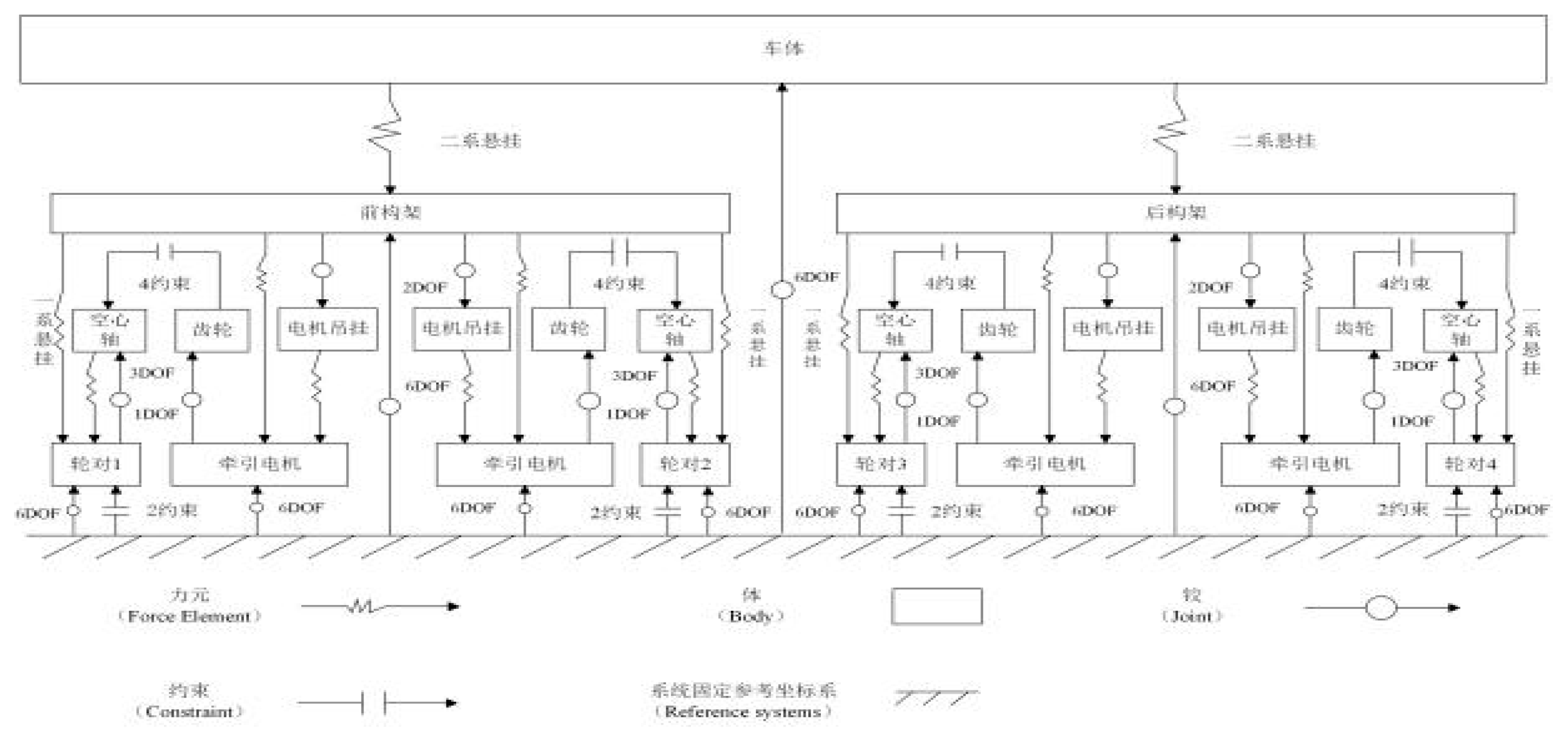
Figure 2.
Schematic diagram of train vertical active control system.
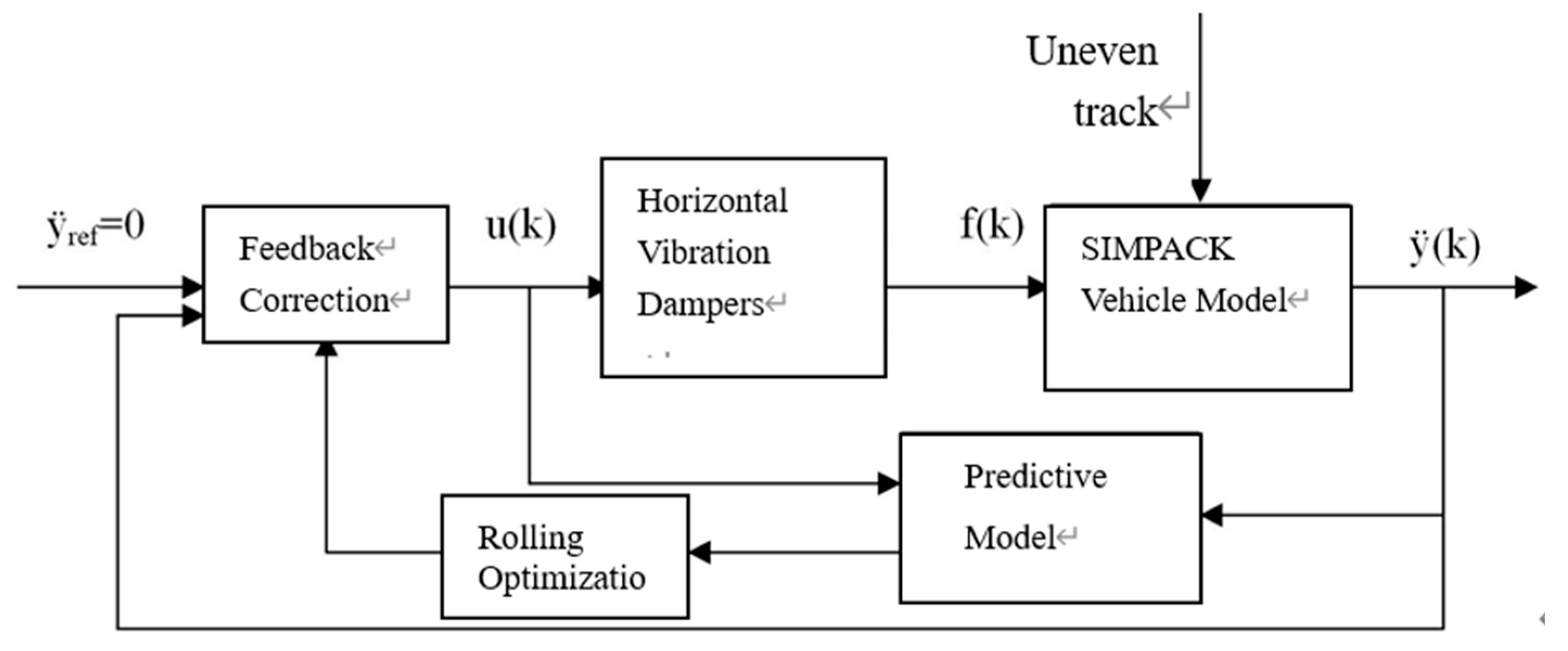
Figure 3.
Block diagram of active control system based on model predictive control algorithm.
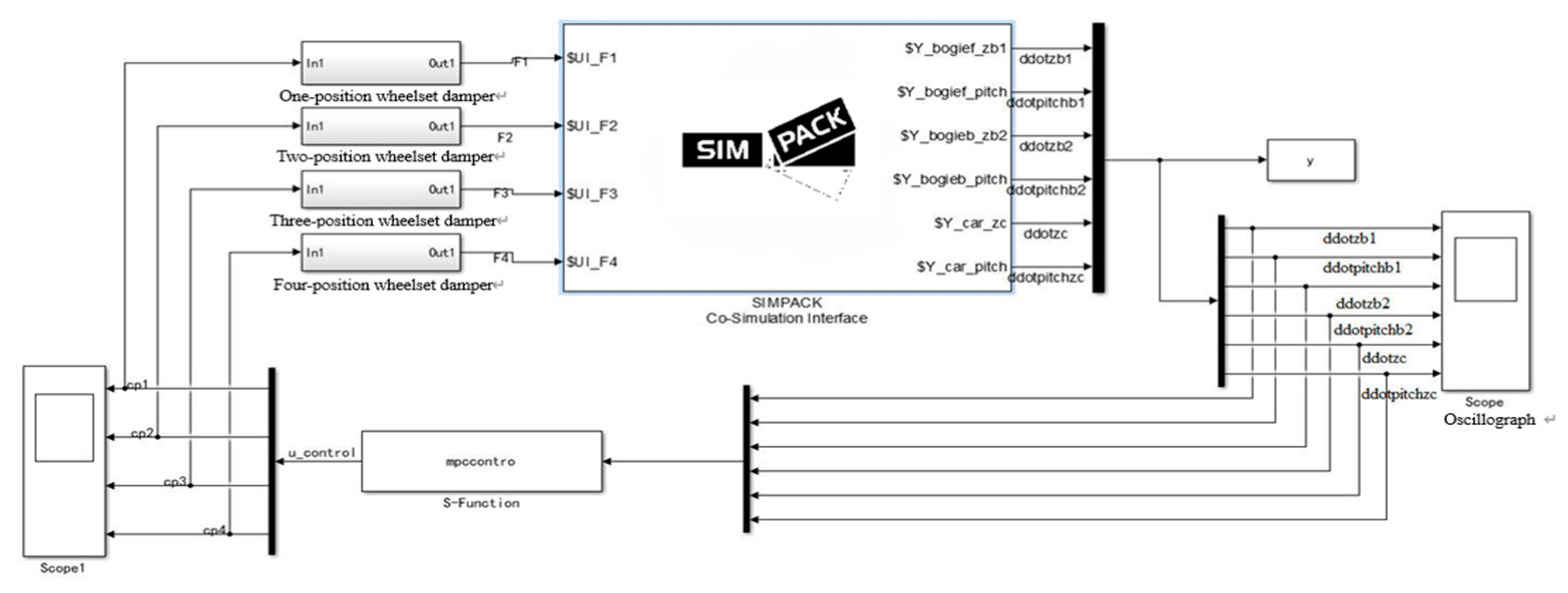
Figure 4.
Comparison of root-mean-square (RMS) values of vertical acceleration for active vs. passive control across speeds.
Figure 4.
Comparison of root-mean-square (RMS) values of vertical acceleration for active vs. passive control across speeds.
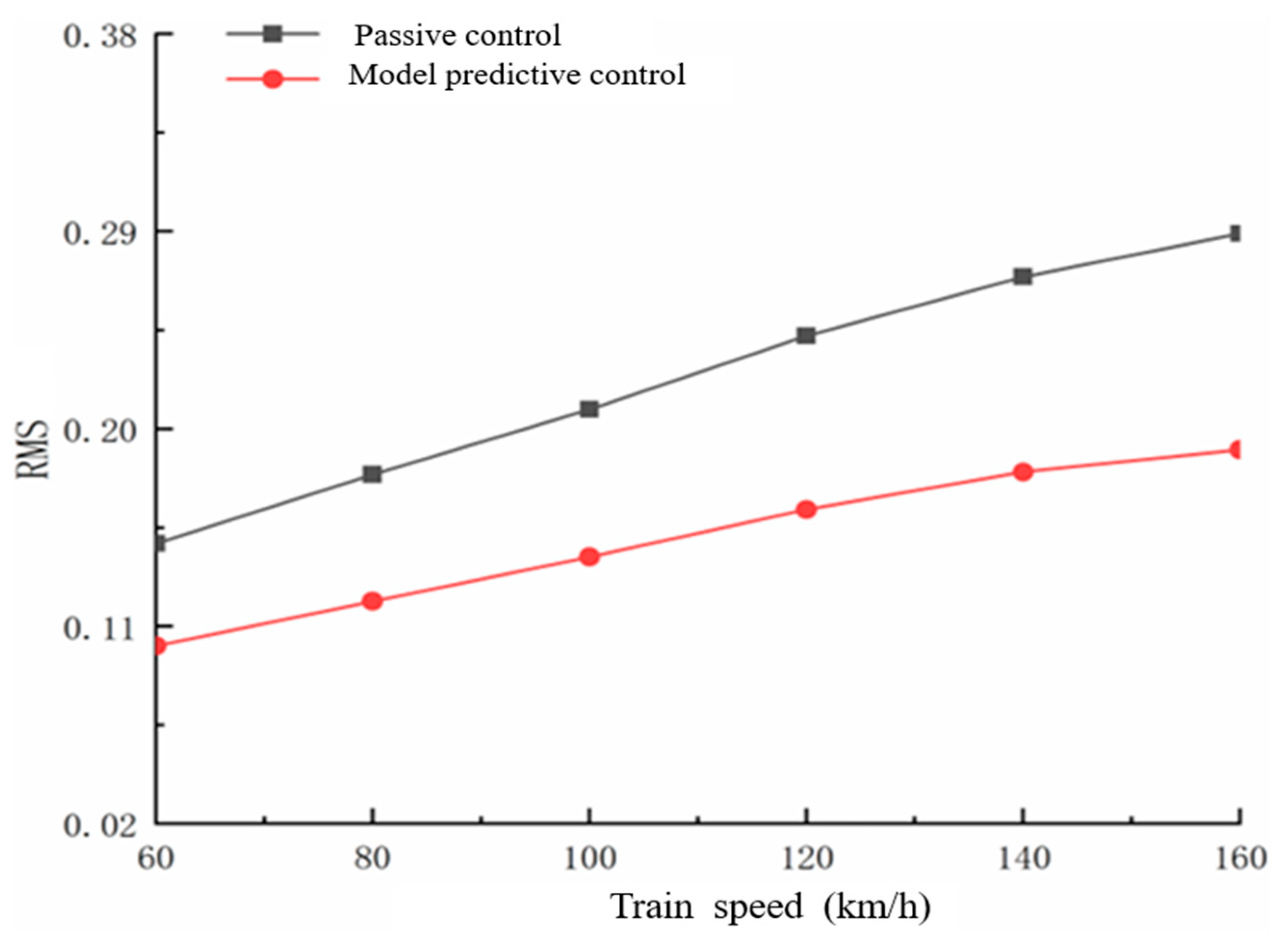
Figure 5.
Sagging comfort indices for car bodies at varying speeds under active and passive control.
Figure 5.
Sagging comfort indices for car bodies at varying speeds under active and passive control.
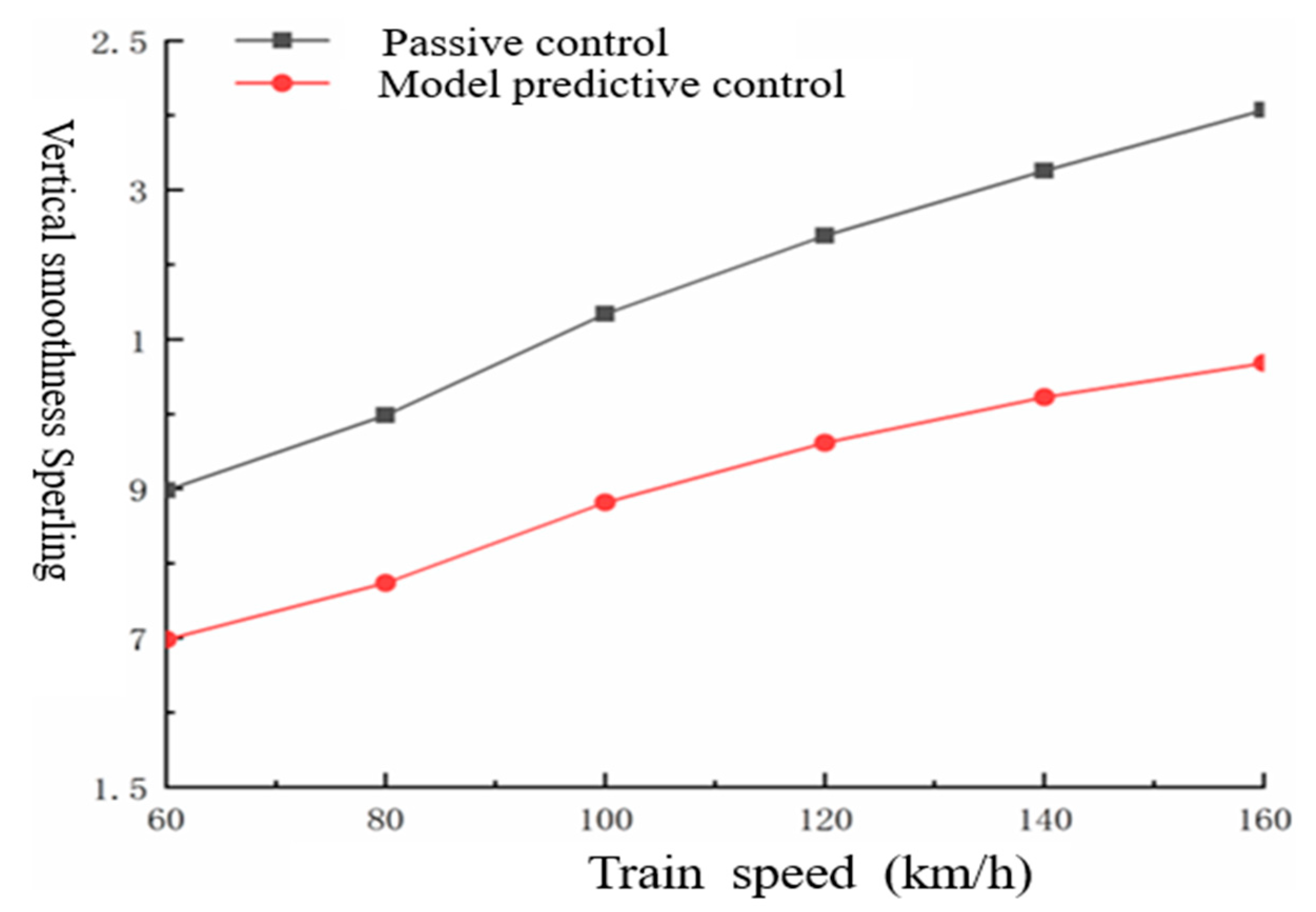
Figure 6.
Comparative analysis of vertical acceleration spectra for car bodies at various speeds.1 Vehicle Model Vertical Dynamics Model.
Figure 6.
Comparative analysis of vertical acceleration spectra for car bodies at various speeds.1 Vehicle Model Vertical Dynamics Model.
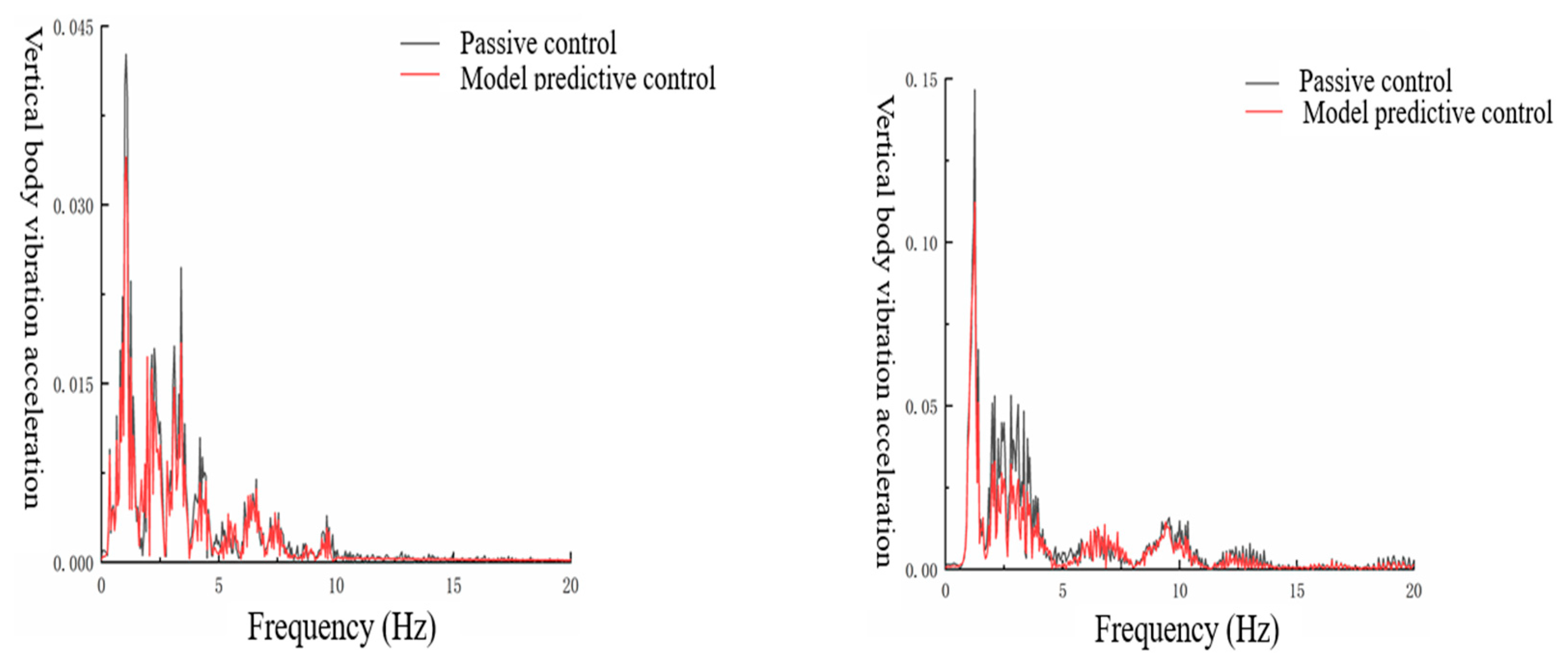

Table 2.
MPC Controller Parameters.
| Parameters | value |
| T(sample step) | 0.01/s |
| Np(predictive time domain) | 20 |
| Nc(control time domain) | 10 |
Table 3.
Evaluation of train comfort.
| Evaluation indicators | Control strategy | Running speed(km/h) | |
| 60 | 160 | ||
| Peak vertical acceleration aw(m/s2) | Passive control | 0.4253 | 0.9023 |
| Model predictive control | 0.3193 | 0.6093 | |
| Root mean square value of acceleration RMS | Passive control | 0.1478 | 0.2891 |
| Model predictive control | 0.1045 | 0.1994 | |
Disclaimer/Publisher’s Note: The statements, opinions and data contained in all publications are solely those of the individual author(s) and contributor(s) and not of MDPI and/or the editor(s). MDPI and/or the editor(s) disclaim responsibility for any injury to people or property resulting from any ideas, methods, instructions or products referred to in the content. |
© 2025 by the authors. Licensee MDPI, Basel, Switzerland. This article is an open access article distributed under the terms and conditions of the Creative Commons Attribution (CC BY) license (http://creativecommons.org/licenses/by/4.0/).
Copyright: This open access article is published under a Creative Commons CC BY 4.0 license, which permit the free download, distribution, and reuse, provided that the author and preprint are cited in any reuse.


