
Submitted:
22 September 2025
Posted:
23 September 2025
You are already at the latest version
Abstract
This study examines the feasibility of incorporating energy harvesting devices into electric vehicles while highlighting their potential to extend battery lifespan. For this purpose, a simulation setup of a real-life scenario was designed and implemented. This setup includes a small-scale electric vehicle powered by a 12.6-volt lithium polymer battery installed on an automated control platform. The platform continuously monitored the current, voltage, and temperature of the battery to enable real-time estimation of its state of charge. Three driving profiles were used in the study to demonstrate their influence on energy demand patterns. Driving Profile A maintained a steady speed of 30 km/h. Driving Profile B used varying speeds based on a sawtooth signal. Profile B used random speeds. The results show that while supplemental energy from energy harvesters is useful for powering accessory systems in electric vehicles, it is insufficient for powering main systems. Nevertheless, it can extend the battery lifespan. These findings contribute to the development of environmentally friendly energy management plans for electric vehicles. This study underscores the importance of sustainable mobility systems in reducing the ecological footprint of transportation.
Keywords:
electric vehicles
; energy harvesting
; batteryless devices
; battery SOC
; driving profiles
1. Introduction
Despite the battery use effectiveness contributes to reducing carbon pollution, it also generates other types of pollution to be addressed. Battery pollution is an issue that persists throughout the entire life cycle of the product, from material extraction and manufacturing to final disposal and handling. This complex problem has different environmental impacts at each stage and various solutions have been proposed. Nevertheless, this study addressed only two approaches: extending battery life and designing battery-free devices. Moreover, it is imperative to perform a comprehensive evaluation of battery performance, assessing not only the energy requirements of the applications in which they are utilized but also the design, architecture, and construction materials for the batteries. Therefore, particular attention must be directed toward the state of charge of the batteries, in accordance with energy requirements. Thus, the present study concentrates exclusively on lithium-ion batteries, whose prevalence in applications of electric and hybrid vehicles can be attributed to their high energy and power density, minimal self-discharge rates, and absence of memory effect.
In the majority of applications today, energy harvesting devices are not yet a viable alternative to lithium-ion batteries. All the same, these gadgets can provide more energy and prolong the life of batteries, particularly in low-power devices. The biggest obstacle is that, in spite of their potential, energy harvesting technologies are unable to match conventional batteries’ high-power density and reliable operation. They can only deliver a certain quantity of energy owing to their limited conversion efficiency. The process of turning environmental energy into electrical power using a variety of sources, including motion (piezoelectric materials), heat (thermoelectric generators), light (solar cells), and radio frequency (RF) waves, is known as energy harvesting. Ion lithium batteries and energy harvesting devices are contrasted in Table 1.
Energy harvesting devices are commonly used in hybrid systems to supply the charge needed for rechargeable batteries or supercapacitors by using the harvested energy. These devices reduce maintenance costs, increase reliability, and extend battery life. In hybrid systems, the battery provides stable backup power when the environmental power source is unavailable and needs to be replaced less frequently. In recent years, research efforts have focused on improving efficiency and reducing the size of energy harvesting devices [1,2,3,4,5]. Advances in nanomaterials and electronic device design have enabled these devices to supply sufficient energy, making them a viable option for battery-free applications. Notwithstanding their unsuitability for high-power applications, they are poised to revolutionize wearable electronics, the Internet of Things (IoT), and other small-scale devices that need to run continuously, utilizing minimal power.
1.1. Related Works
Extensive studies have emerged on the cutting-edge field of energy harvesting, with some focusing on the development of energy harvesting devices and systems that employ a variety of technologies and strategies. For instance, Xing et al. [6] proposed a hybrid electromagnetic active suspension system that integrates a hydraulic-electromagnetic energy regenerative module and a linear motor. Under Class C road excitation, they discovered that active suspension improves suspension dynamic deflection by 12.7% and body acceleration by 21.5% when compared to passive suspension. Furthermore, it achieved an energy recovery of 29.9 W and showed a 67.8% reduction in energy usage when compared to a linear motor active suspension. As it concurrently enhances vehicle dynamics, lowers energy consumption, and promotes energy recovery, the method proposed by Xing et al. [6] can thus be regarded as a workable and effective solution. Furthermore, an inflatable hydraulic-electric regenerative suspension system for heavy-duty trucks was proposed by Zhang et al. [7]. The device recovers energy that would otherwise be lost during suspension operation while reducing vibrations brought on by uneven roadways by combining hydraulic and inflatable components. In contrast, Chiu et al. [8] designed a vibration energy harvesting system based on a magnetic mass-spring system that harnesses the vibrations of a suspension system. Three dimensionless indices were introduced to evaluate system performance and ride comfort: regenerated electricity transmissibility, displacement transmissibility, and ride comfort. Subsequently, a multi-objective optimization function was used to integrate these indices with three weighted factors, along with the simulated annealing method, to ascertain the optimal physical parameters of the device. Behara et al. [9] conducted an investigation into a vibration absorption system that integrates a telescopic assembly within a vehicle shock absorber. The primary objective of this system was to enhance the efficiency of energy harvesting from vibrations generated during vehicular operation. Its dynamic performance was rigorously analyzed and experimentally validated to determine its capacity for energy recovery. Correspondingly, Zhou et al. [10] presented and examined a regenerative magnetic suspension system for vehicles, providing further insights into advanced strategies for energy recovery in automotive applications. This system is characterized by its high safety standards, compact design, and ease of maintenance. It incorporates an electromagnetic generator with traditional passive suspension and uses a quarter-vehicle (one-axle) model to theoretically analyze how the suspension behaves under periodic excitations. This study also examined the impact of electromechanical coupling and external resistance. Sani et al. citeSani2024 also addressed a critical issue in energy recovery from frictional vibrations in vehicle braking systems. Even so, the voltage generated was only significant at low speeds. To address this challenge, they proposed leveraging ambient vibrations caused by rotational imbalances in vehicle components. To do so, they modeled the dynamic behavior of a disc brake pad. Their model is considered a non-smooth stick-slip oscillator with Stribeck-type friction and an unbalanced mass on a shaft that generates parametric excitation. In the context of small devices that harvest energy for low-power electronic devices, Urbina et al. [11] developed an electromagnetic generator system integrated into a bicycle wheel. This system is based on a kinetic-electromagnetic transducer that is optimized by a Halbach-type magnet array. Also, Minazara et al. [12] developed a bicycle-mounted piezoelectric generator designed to harvest the mechanical energy generated by vibrations while riding. The system includes a piezoelectric transducer that vibrates with the vehicle’s motion, producing electricity. This energy is then converted by a static converter into a form suitable for powering portable devices. Additionally, Jettanasen et al. [13] designed and evaluated a piezoelectric power generation system on a bicycle for use as a micromobility device in smart city settings. They began by modifying a stationary bicycle (such as an exercise bike) with a piezoelectric generator and then implemented a mobile prototype using a conventional bicycle equipped with piezoelectric modules, magnets, and harvesting electronics (including a rectifier, regulator, battery, and controller) capable of powering sensors and LED lights on the bicycle. Abdurrahim et al. [14] conducted a numerical study using the finite element method of a piezoelectric energy harvester to see its visibility for application in harvesting motorcycle vibration, considering the target vibration typical of 40-60 Hz.
Meanwhile, technological advances have given rise to portable and wearable electronic devices that have emerged as innovative energy solutions. This has increased the demand for sustainable and adaptable energy sources in daily life. In this regard, Han et al. [15] conducted a study focusing on self-charging power systems that combine energy storage systems, such as rechargeable lithium-ion batteries, with solar, mechanical, thermal, or chemical energy harvesting systems. The study explores various approaches to optimizing individual components and integrated power systems for portable and flexible electronic devices. It also covers systems that combine multiple energy harvesting strategies, and pays special attention to design considerations, advances in materials, and engineering challenges. It should be noted that self-charging power systems were created in order to either decrease the frequency of power supply system recharges or increase system runtime and energy self-sufficiency.
As the number of IoT devices continues to grow, it has become critical to ensure a sustainable and environmentally friendly energy supply for sensors and wireless devices. Conventional batteries are currently insufficient to address the growing energy requirements of Internet of Things (IoT) ecosystems. Significant advances have been made in the electronics of IoT sensor devices, and other developments continue to emerge. These include innovative approaches to energy optimization and battery-free solutions based on energy harvesting technologies. By way of illustration, Tanweer et al. [16] proposed an energy harvesting solution based on sustainable electrodes that uses the capabilities of printed electronics technology. Specifically, the study addresses the design of electrodes placed on diaper back sheets to collect green energy from urine. The study aimed to develop wearable and energy-efficient IoT sensors for battery-free smart diapers. To this end, experimental methodologies were employed to characterize sustainable harvesting electrodes in a controlled laboratory setting.
More specifically, studies like this should be considered related work. For example, Liu et al. [17] reviewed progress on major applications powered by advanced energy harvesters up to 2021. The review begins by examining the evolution of energy harvesting technologies. Then, it discusses self-powered sensors and self-sustaining IoT applications. The review also considers typical and emerging applications in smart homes, gas sensing, human monitoring, robotics, transportation, blue energy, aircraft, and aerospace. In these areas, energy harvesting is considered an alternative or a complement to batteries. De-Oliveira et al. [18] proposed a power management system that uses radio frequency (RF) energy harvesting to provide a stable 0.4 v direct current (DC) power supply for low-voltage systems. Likewise, Gao et al. [19] conducted a review of advances in energy harvesting and storage technology up to 2024 that could eliminate the need for battery replacement for powering wearable and implantable medical devices. Also, Ali et al. [20] examined energy harvesting techniques for sustainable IoT devices. The primary focus of their research was on low-powered piezoelectric sensors and actuators in various industries. They considered the potential of these techniques to eliminate the need for batteries and address the growing demand for sustainable IoT devices. In parallel, Safaei et al. [21] conducted a comprehensive study of 400 recent publications on energy harvesting technologies and their application in the IoT context. The study made two assumptions. Firstly, energy harvesters have emerged as a viable alternative, enabling IoT devices to operate autonomously and sustainably. This approach has been shown to minimize maintenance needs and enhance system reliability. Secondly, traditional batteries require replacement, resulting in higher maintenance costs, downtime, and environmental concerns related to the final disposal of the batteries.
1.2. Research Context
None of the studies focus on direct, one-to-one replacement of lithium-ion batteries with energy-harvesting devices in all applications. Instead, the primary objective of research in this area is to strategically integrate energy harvesting devices into hybrid systems, thereby providing a complementary energy source. Hybrid systems offer a viable solution to address the challenges associated with intermittent energy sources. These devices are engineered to prolong battery life and utilize progressively smaller batteries, particularly in low-power electronic devices. Current research efforts are focused on addressing the limitations of lithium-ion batteries when used with energy harvesting devices. This is a comprehensive summary of essential study strategies.
- Research and development in enhancing energy harvesting efficiency. Researchers are developing methods to maximize the power output of energy harvesting devices. This includes creating new materials, such as triboelectric nanogenerators, that efficiently convert mechanical energy into electricity. Case in point, Khan et al. [22] developed an energy valley optimizer based on the maximum power point tracking (MPPT) algorithm to extract maximum power from solar. Also, Liao et al. [23] studied the cellulose-based triboelectric nanogenerators as a promising solution for energy harvesting and proposed some strategies to improve their performance and sustainability. In addition, Mondal et al. [24] studied some hybrid energy harvesting devices as a desirable approach to improve power efficiencies due to their ability to utilize multiple energy sources simultaneously. In this regard, Sevcik et al. [25] provided a general overview of the subsystems present in the energy harvesting systems, as well as a comprehensive review of the energy transducer technologies used in these systems. Other researchers are improving solar and thermal energy technologies [26,27,28,29].
- Hybrid systems for IoT and wearable devices. A significant number of studies are underway to explore the integration of energy harvesting into IoT sensors, wireless sensor networks, and wearable devices [30,31]. Consequently, innovative devices are being developed to eliminate the need for user intervention to replace batteries. In particular, Abdulmalek et al. [32] introduced the design and development of an Internet of Wearable Things-based hybrid healthcare monitoring system for smart medical applications, incorporating smart wearable sensing units for real-time, remote monitoring of vital health parameters such as blood pressure, heart rate, and body temperature. Specifically, in the study of Nishanth and Senthilkumar [3], in which a small solar cell or a piezoelectric device in a fitness tracker was proposed to continuously recharge a miniature lithium-ion battery, thereby extending its lifespan from months to years. A thorough analysis of recent advancements in energy harvesting systems for wearable technology is presented in the study by Ali et al. [33]. This study provides a detailed examination of methodologies for wearable energy harvesting, with a particular emphasis on the harvesting of heat and mechanical energy from the human body. Additionally, it provides a systematic review of diverse portable energy harvesters, addressing their manufacturing processes, operational characteristics, and production outcomes. The study encompasses a range of devices, including piezoelectric, electrostatic, triboelectric, electromagnetic, thermoelectric, solar, and hybrid systems.
- Advanced energy storage and harvesting systems. The development of portable energy storage and harvesting devices is essential for many daily activities. For instance, these devices are used in advanced healthcare technologies that enable real-time monitoring. Traditional portable devices have been limited by bulky, rigid batteries, which hinder their practicality and comfort. However, recent advances in materials science have made flexible, elastic, lightweight energy storage and harvesting solutions possible. Integrating these technologies is essential for developing self-sufficient systems that minimize dependence on external power sources and extend device lifespans. These integrated systems ensure the continuous operation of vital sensors and processors in real-time processes. In this regard, the study by Zhang et al. [34] examines recent advances in portable energy storage and harvesting with a focus on wearable devices, solar cells, biofuel cells, triboelectric nanogenerators, magnetoelastic generators, supercapacitors, lithium-ion batteries, and zinc-ion batteries. The study also analyzes key parameters crucial to portable electronic devices, such as energy density, power density, and durability. Finally, the review addresses future challenges and prospects, highlighting the potential for developing innovative, autonomous wearable systems for healthcare applications. Conversely, to address the discrepancy between the intermittent nature of energy harvested from the environment and the constant energy requirements from devices, advanced energy storage solutions are being studied [35,36,37,38,39]. Due to their fast charging and discharging capabilities and large number of cycles, supercapacitors are a study of research as an alternative to the irregular energy production of energy harvesting devices [40,41,42,43]. Some studies aim to replace batteries entirely with super capacitors, while others seek to combine the two technologies to create a hybrid energy storage solution [44,45,46,47].
- Smart energy management systems. These are systems essential for any hybrid system. Studies in this area focus on developing smart circuits that can efficiently manage energy supplies from energy harvesting devices and batteries [15,48,49]. These smart systems can dynamically control the energy supplied by two energy sources, ensuring that the system always has a stable power supply and maximizing the use of harvested energy [50,51,52,53]. To illustrate, Yaseen et al. [54] studied and evaluated the effectiveness of dynamic energy management strategies, explored energy harvesting methods to improve sustainability, and created a framework to develop efficient and resilient IoT systems.
1.3. Contribution
It was decided that this study will concentrate on hybrid systems for wearable technology and the Internet of Things out of the four research topics examined in Section 1.2. To that end, a case study was prepared based on a scale model of an electric vehicle, considering three driving profiles and a supervision and control system. The key contributions from the study are explained as follows:
- It provides experimental data on the correlation between driving profiles and the state of charge of the battery when used in an electric vehicle. This approach is based on the principle of ensuring an optimal balance between safety and efficiency in operation. It facilitates the estimation of battery life, as indicated by its charge-discharge cycles and subsequent capacity degradation. Moreover, it enables the calculation of the discharge curve, thus providing insight into the available electrical energy within the battery.
- Consequently, it offers experimental findings on the viability of employing commercial energy harvesting devices as a supplementary energy source in a small-scale electric vehicle, intending to reduce the reliance on traditional battery systems.
The paper is organized to address these objectives. Section 2 explains the study’s theoretical considerations, outlines the methodology and procedures, and introduces a case study involving a 1:10 scale electric car model. Section 3 details the experimental setup, settings, and results of applying the methods to three distinct driving profiles. This section also demonstrates how energy harvesting devices can supplement the lithium polymer battery to reduce its load and extend its lifespan. Finally, Section 4 presents the discussion and conclusions.
2. Materials and Methods
2.1. Considerations
A battery is an electrical device that converts chemical energy into electrical energy. Typically, it is made up of one or more cells arranged in a serial or parallel configuration, depending on the desired output and the storage capacity of the battery. A battery cell consists of an anode (negative electrode) and a cathode (positive electrode), along with an electrolyte. The theoretical capacity of a cell is defined by the quantity of reactive material it contains (in Coulombs or amp-hours). This quantity defines the total electric capacity produced by an electrochemical reaction. The battery constitutes the most expensive component of an electric vehicle. To ensure that vehicle autonomy is managed effectively and battery health is maintained, it is essential to determine the state of charge (SOC) of the battery under various driving conditions. A comprehensive understanding of SOC is crucial to determine the residual energy in the battery and the distance that the vehicle can travel before requiring recharging. Given the inevitable degradation of batteries over time, effective management of their SOC is critical to extending their useful life and preventing premature deterioration. Therefore, it is essential to estimate a discharge curve for a battery, which shows the rate of voltage decrease over time under various vehicle driving conditions.
The methodology used for this study to determine the correlation between driving profiles and the state of charge of the battery when an electric vehicle is used considering the discharge curve of a battery. This critical metric is of great value to engineers, designers, and users. It provides essential data on the performance, efficacy, and useful life of a battery under various vehicle driving conditions. These curves are used by engineers to design circuits and systems that implement battery management systems (BMS), which can effectively work despite variations in battery voltage. A BMS plays a key role in determining the cut voltage, which is indicative of the point at which the system must be deactivated to prevent battery damage resulting from excessive discharge. Furthermore, the available useful capacity of the battery can be calculated in amp-hours by determining the area enclosed by the discharge curve. This procedure confirms that the battery meets the specifications outlined in the datasheet provided by the manufacturer. The discharge curve is a tool that is used to analyze the impact of the discharge rate (C-rate) on the state of health of the battery. This curve is subject to variation depending on the rate at which energy is extracted from the battery. In essence, the discharge curve indicates that accelerated discharge, typified by a high C-rate, leads to significant loss and decreased battery capacity. This relationship facilitates comprehension of the interaction between power and duration. In addition, a discharge curve is a key diagnostic tool for assessing battery conditions. As batteries age, this curve changes over time, making it more evident when the battery is deteriorating. Hence, a comparison of the discharge curves throughout the life of the battery can be used to estimate its state of health and predict the time to replace it. Alongside, manufacturers generally provide a discharge curve to facilitate designers in selecting the optimal battery for a specific device.
2.2. Method Description
The procedure in this study is based on the SOC concept for the battery. It is applied to each of the three driving profiles of an electric vehicle coupled to the docking platform, and to obtain the voltage, current, and temperature of the battery, along with the vehicle speed. This procedure estimates the performance of the battery by the speed of the vehicle and the SOC of the battery.
The SOC indicates the percentage of total capacity that remains and represents its current charge level. Essentially, the SOC is a battery charge indicator that shows how much energy is left before the battery needs to be recharged. However, the SOC has to be estimated using alternative methods. One of the following three techniques is used to estimate it: Coulomb counting, voltage measurement, or a Kalman filter. The most common method is Coulomb counting. With this method, the total charge removed or added is calculated by measuring and integrating the current flowing into and out of the battery over time. Although accurate in the short term, small measurement errors can accumulate, resulting in inaccuracies over time. The voltage method uses a predefined lookup table or discharge curve to correlate the voltage of the battery with the SOC. This method is simpler, but less accurate because the voltage can be affected by factors such as temperature, discharge rate, and battery age. Finally, the Kalman filter method is an advanced technique that combines Coulomb count and voltage measurements to provide a more accurate estimate. Using a dynamic battery model, it continuously corrects the estimated SOC based on real-time sensor data, making it more resistant to measurement errors.
- i.
- The vehicle battery should be fully charged (12.6 V).
- ii.
- Couple the electric vehicle with the docking platform.
- iii.
- Select a driving profile, then begin the experiment by starting the operation of the electric vehicle.
- iv.
- Acquire the voltage, current, and temperature of the vehicle battery.
- v.
- Save the data to the microSD memory card. The data can be viewed on the organic-LED screen of the electronic system
- vi.
- Estimate the battery SOC using the Coulomb counting method described by Eq. 1where is the battery SOC at the beginning of each experiment, that is when the battery is fully charged (100%) to 12.6 V, is the current and is the nominal capacity of the battery. Furthermore, is the initial time and t is the current time during the experiment. For this study, the battery datasheet specifies Ah.
- vii.
- Repeat this procedure for each driving profile.
Since the state of charge of the battery is not used directly in the calculation, sizing energy harvesting circuits requires an indirect approach that balances power consumption and generation. Note that the SOC indicates the battery’s current state but does not directly reflect the necessary power. Therefore, the calculation must quantify the energy consumption and capacity of the system, together with the necessary energy harvesting to maintain or increase the SOC while the battery-powered system is operating. This process is described by considering the following four steps:
- a.
- Calculate the power consumed as .
- b.
- Determine the power output of a single energy harvester (). This information can be found in the provided datasheet of the energy harvester, or it can be calculated according to its configuration and structure. Note that the power source and the efficiency of the conversion circuit affect .
- c.
-
Determine the smallest number of energy harvesting circuits () that would allow the system to operate indefinitely and produce a total power that is at least equal to the average power consumption. That is,Therefore, should be estimated according to Eq. 3.where represents that the number should be rounded up to the next whole number since a fraction of an energy harvesting circuit cannot be used.
In this approach, note that the battery serves as a buffer between the intermittent power supply and the system’s energy demand. is the key metric used to verify the precision of the energy supply system design. A decreasing indicates that the generated power is less than the consumed power. This indicates that the battery is discharging to compensate for an energy deficit caused by insufficient energy harvesters. In contrast, if remains stable, then the system is in equilibrium, meaning the energy generated equals the energy consumed. This condition may be acceptable if the system does not need to operate for extended periods without an energy harvesting source. Finally, increasing means that more energy is being generated than consumed. This is the ideal condition to ensure that the battery is fully charged when energy is available (e.g., at night in a solar system). In short, an energy harvesting circuit must generate enough power to match the system’s average consumption to be considered effective. However, it should generate more power than is consumed to recharge the battery.
2.3. Case Study
This section presents a case study in which the voltage and current supplied by a lithium-ion battery are measured to monitor and control electric vehicle systems. The study is based on an experimental setup designed to quantify total energy consumption and estimate battery discharge curves. The battery is installed in a 1:10 scale model of an electric vehicle (see Figure 1 ).
It is important to note that this electric vehicle consists of mechanical, electrical, and electronic components. It is coupled to the docking platform shown in Figure 2 with bearings that allow the vehicle’s wheels to rotate without moving the vehicle, as shown in Figure 3.
The propulsion system of the electric vehicle consists of a Velineon 3500 brushless motor with a rotor containing neodymium magnets and a stator containing coils. An electronic motor drive regulates the motor’s speed and power. The vehicle also has a radio frequency transceiver that receives and transmits control signals according to the selected driving profile during docking platform tests. The motor drive acts as an actuator, allowing the operating conditions of the brushless motor to be selected. The motor shaft is coupled with a gear system that amplifies the motor’s torque, enabling the wheels to turn forward or backward.
Since batteries are essential for powering vehicles, this study focuses on key aspects of their macroscopic behavior, such as open-circuit voltage, temperature, age, and speed-dependent capacity. The open circuit voltage occurs when the battery reaches internal equilibrium without being connected to it. This voltage depends on the state of charge, temperature, and charge-discharge history of the battery, also known as hysteresis. Under these conditions, it is assumed that battery temperature influences internal resistivity. Therefore, as the battery temperature increases, electronic activity increases, resulting in a smaller internal resistance and a greater current.
3. Results
3.1. Experimental Conditions and Settings
This section describes the driving profile module, the electronic system that measures the current, voltage, and temperature of the battery, and the electronic system that measures vehicle speed.
-
Driving profile module. It is external to the electric vehicle and produces three digital signals that determine the speed of the vehicle. It consists of a microcontroller, programmed in the C language, that stores three driving profiles in a nonvolatile memory.
- –
- Profile A. It corresponds to a constant speed of 30 km/h,
- –
- Profile B. It corresponds to a variable speed with constant increments according to a sawtooth signal, and
- –
- Profile C. It corresponds to a driving profile that involves random speeds.
The digital voltage produced in each profile is then converted to an analogue format using a digital-to-analog converter and can be transmitted by the RF transceiver to the electric vehicle. - An electronic system that measures the current, voltage, and temperature of the battery. The electric vehicle includes a lithium polymer battery (LiPo) with a nominal voltage of 12.6 volts and a capacity of 5000 mA/h. To measure the voltage, current, and temperature of the battery, the electric vehicle is placed on the docking platform, the battery is fitted with sensors, and a driving profile can be chosen. Sensor signals are displayed on an organic-LED screen and stored on a microSD memory card that can be accessed by other devices or computers to process, analyze, and interpret.
- An electronic system was implemented to monitor vehicle speed. It was implemented to monitor the speed of the electric vehicle in each experiment. This system uses a photoelectric sensor with a digital output that is placed behind the vehicle wheel. The wheel was notched to interrupt the light from the LED emitter traveling to the LED detector, which changes its output voltage from logic one to zero. The microcontroller includes code that interprets this sequence of digital pulses and calculates the revolutions per minute of the vehicle wheels, which are converted to vehicle speed in kilometers per hour. In this way, the vehicle speed is displayed on the organic-LED screen.
This study considered three experiments, each corresponding to one of the three driving profiles defined in Section 3.1. At the beginning of each experiment, the vehicle battery was fully charged at 12.6 V and was considered fully discharged when it reached 9.25 V. When the battery is fully discharged, it disconnects from the propulsion system.
3.2. Experiment Based on Driving Profile A
Figure 4 shows the results when Driving Profile A is selected and the vehicle’s speed is kept constant at 30 km/h. The voltage, current, and temperature of the battery were monitored during a 35.5-minute experiment. The black line indicates the voltage, and the blue line indicates the current. Note that an average current of 8 A was drawn from the battery. The red line indicates the behavior of the battery temperature, which increased by 5.25°C starting from 21.5°C.
Note, in Figure 5, that after 36 minutes the SOC of the battery reached the full-discharge state.
3.3. Experiment based on Driving Profile B
Based on Driving Profile B, the electric vehicle had a speed between 0 and 80 km/h (see Figure 6) corresponding to the sawtooth signal in the control drive. In a similar way to the previous case, the black line indicates the voltage and the blue line indicates the current provided by the battery from 0 to 40 minutes, being 40 minutes when the vehicle battery reached its fully discharged state. In addition, the red line represents the behavior of the battery temperature changing between 23°C and 27°C.
After 40 minutes, the SOC of the battery reached 16% (see Figure 7).
3.4. Experiment Based on Driving Profile C
Based on Driving Profile C, the electric vehicle had a random speed between 0 and 80 km/h (see Figure 8) according to a random signal provided from the control drive. Similarly, the black line represents the voltage and the blue line represents the current, both provided by the battery from 0 to 40 min., demanding from 0 to 15 A, and lasting 40 minutes when the vehicle battery reached its full-discharge state. In addition, the red line shows the behavior of the battery temperature changing between 22°C and 28°C.
After 40 minutes, the SOC of the battery reached approximately 2.5% (see Figure 9).
Furthermore, Table 2 shows the results obtained for the three driving profiles in open-loop mode.
3.5. Integration of Wind Energy Harvesters into the LiPo Battery System
This section describes how to replace the lithium polymer battery in a 1:10 scale model of an electric vehicle with an electric wind microturbine. This microturbine consists of a 4-vane fan, each 100 mm high, and a high-speed electric motor. This motor has the following features: high torque (130 magnetic brushed), DC voltage: 3-12 V; No-load speed: 9000-25000 RPM ±10%; Motor body diameter: 27 mm; Shaft size: 10 mm×2.0 mm; Motor body length: 38 mm. In addition, note in Figure 10 that the wind vane is arranged vertically, not horizontally, allowing the microturbine to capture energy regardless of the wind direction. Therefore, this electric motor was used in a wind turbine when it was set up to generate energy. Following the procedure described in Section 2.2.
- a.
- Determining the power consumption of the system to be considered. Figure 11 shows the instantaneous power consumed by the 1:10 scale model of the electric vehicle used in this study. The black line in the graph indicates the power consumption when Driving Profile A is utilized, the red line when Driving Profile B is employed, while the blue line corresponds to Driving Profile C. Note that = is the instantaneous power supplied by the battery, and and are the instantaneous voltage and current of the battery of the electric vehicle.
- b.
-
Determine . In this case, considering that the microturbine is based on a Savonius rotor [55], is given according to Eq. 4 and it is showed in Figure 12 for three driving profiles. Similar to Figure 11, in Figure 12 the black line in the graph indicates the power consumption when Driving Profile A is utilized, the red line when Driving Profile B is employed, while the blue line corresponds to Driving Profile C.where H is the height of the rotor in meters, D is the diameter of the rotor in meters, and v is the wind speed in meters per second.Based on Figs. Figure 11 and Figure 12, Figure 13 illustrates the power requirements of the LiPo battery over time when two energy harvesters (microturbines) are integrated into the electric vehicle, under the assumption that driving profiles A, B, and C are used, considering that = .Therefore, the rotation speed, n of the used microturbine can be defined according to Eq. 5.where is a dimensionless quantity representing the specific speed of the microturbine and it is given by Eq. 6, assuming that is the angular speed of the rotor.Note that in this case 1 as the angular speed at the end of the rotor vanes is approximately equal to the wind speed. That is, .Accordingly, Figure 14 shows n considering the three driving profiles. Note that n is in the range (0, 2800) RPM, which is considered adequate for the selected motor, whose rotation speed is in the range (0, 25000) RPM.
- c.
-
Determine . Table 3 shows calculated using Eq. 3, taking into account the average speed of the electric vehicle for each driving profile and estimated using Eq. 4.On the other hand, considering that only two microturbines () can be implemented in the electric vehicle and, according to Driving Profile A, it can be assumed that , from Eq. 3 the energy harvester should then produce at least 50 W and the electric vehicle should maintain a constant speed km/h so that the energy harvesters can reach the power level original consumed. However, operating electric vehicles under these conditions will result in higher power requirements when other driving profiles are considered.
4. Discussion and Conclusions
To establish a baseline for the energy requirements of a scaled vehicle, this study examined the fuel economy data reported by the US Environmental Protection Agency (EPA) in 2017. The report emphasizes the superior efficiency of electric vehicles compared to gasoline-powered ones. Furthermore, the report shows that the energy consumption of the electric vehicle is consistent with the values in Table 4, especially when applied to a 2012 Nissan Leaf and adjusted for charging losses estimated by the Argonne National Laboratory for different models of electric vehicles.
In the context of electric vehicles, energy harvesting technologies are a promising strategy to generate green energy while minimizing environmental impact during conversion. Integrating these technologies can power auxiliary electric systems and reduce the net demand on the primary energy storage unit. Beyond transportation, this concept aligns with the broader vision of sustainable mobility by improving energy efficiency and reducing the dependence on conventional lithium-ion batteries. However, replacing these batteries with harvesting systems requires the development of advanced devices that can efficiently capture and convert ambient energy sources, such as vibrations, thermal gradients, and airflow, into usable electrical energy. Such systems are particularly relevant for low-power IoT and wireless sensor network (WSN) applications, as they can extend operational lifetimes and reduce maintenance costs. Nevertheless, their implementation is currently limited by low power density and conversion efficiency. This underscores the need for further research on scalability, integration, and hybrid solutions that can bridge the gap between low- and higher-power demands. Exploring alternative energy storage solutions, such as sodium-ion batteries, and developing advanced recycling strategies is critical to addressing the growing challenges associated with lithium-ion technology. These approaches aim to reduce the dependency on lithium resources and improve the sustainability and circularity of energy storage systems. Current research focuses on identifying technological alternatives that can meet the requirements of higher-power applications, a domain currently dominated by lithium-ion batteries. In this context, the present study provides a practical demonstration of replacing the lithium-ion battery of a small electric vehicle with a series of direct current (DC) wind generators. This case study highlights the potential for integrating energy harvesting systems as complementary or alternative solutions, paving the way for more resilient, eco-friendly, and diverse energy architectures for future electric mobility.
In this study, discharge curves were obtained for a LiPo battery used in a scale model of an electric vehicle considering three driving profiles. The experiments for each driving profile were carried out in a docking platform that integrates the driving profile module, the electronic system that measures the variables of interest linked to the battery, and the electronic system to monitor the vehicle speed. For these systems, the main component was a microcontroller that includes a code to determine whether the speed of the electric vehicle is constant, sawtooth, or random. The voltage, current, and temperature of the battery as a time function, as well as the vehicle speed, can be observed on a computer. Note that the vehicle battery was fully discharged at 35.5 minutes for Driving Profile A, with a required mean current of 8 amps and an increase in temperature of 5.25°C. Using Driving Profile B, the vehicle battery was fully discharged at 39 minutes when the required current was between 0 and 15 A, and its temperature was between 23°C and 27°C. Finally, using Driving Profile C, the battery was fully discharged at 40 minutes when the demand current was between 0 and 15 amps and its temperature was between 22°C and 28°C.
Author Contributions
For research articles with several authors, a short paragraph specifying their individual contributions must be provided. The following statements should be used “Conceptualization, O. Jiménez-Ramírez and R. Vázquez-Medina; methodology, D. Aguilar-Torres, O. Jiménez-Ramírez, and J. C. Paredes-Rojas; software, D. Gutiérez-Rosales; validation, O. Jim enez-Ramírez, E. Carvajal-Quiroz, and R. Vázquez-Medina; formal analysis, O. Jiménez-Ramírez and D. Aguilar-Torres; investigation, J. C. Paredes-Rojas; resources, X.X.; O. Jiménez-Ramírez and R. Vázquez-Medina; data curation, E. Carvajal-Quiroz and D. Gutiérrez-Rosales; writing—original draft preparation, R. Vázquez-Medina, D. Aguilar-Torrez, and D. Gutiérrez-Rosales; writing—review and editing, E. Carvajal-Quiroz, J. C. Paredes-Rojas, and O. Jiménez-Ramírez; visualization, J. C. Paredes-Rojas; supervision, R. Vázquez-Medina and O. Jiméz-Ramírez.; project administration, R. Vázquez-Medina; funding acquisition, R. Vázquez-Medina, O. Jiménez-Ramírez, and E. Carvajal-Quiroz. All authors have read and agreed to the published version of the manuscript.
Funding
This research was funded by Instituto Politécnico Nacional [Grant numbers: SIP-20250094 (E. Carvajal-Quiroz), SIP-20250154 (O. Jiménez-Ramírez)], and SIP-20250150, SIP-20250321 (R. Vázquez-Medina)].
Conflict of interest/Competing int
Institutional Review Board Statement
Not applicable
Informed Consent Statement
Not applicable
Data Availability Statement
Dataset available on request from the authors
Acknowledgments
D. Aguilar-Torres (CVU-829790) and D. Gutiérrez-Rosales (CVU-1269306) are grateful for the grant provided by Secretaría de Ciencia, Humanidades, Tecnología e Innovación (SECIHTI, Mexico)
Conflicts of Interest
The authors declare no conflict of interest.
Abbreviations
The following abbreviations are used in this manuscript:
| BMS | Battery management system |
| LED | Light-emitting diode |
| IoT | Internet of Things |
| DC | Direct current |
| RF | Radio frequency |
| SOC | State of Charge |
| EPA | Environmental Protection Agency |
References
- Umamaheswari, B.; Santhosh, S.; Ulugbek, A.; Singh, R.; Abbas, A.H.R.; Sherje, N.P. Innovative approaches to harvesting and storing renewable energy from ambient sources. E3S Web of Conferences 2024, 540, 13016. [Google Scholar] [CrossRef]
- Kang, M.; Yeo, W.H. Advances in energy harvesting technologies for wearable devices. Micromachines 2024, 15, 884. [Google Scholar] [CrossRef]
- Nishanth, J.R.; Senthilkumar, B. Hybrid energy harvesting by reverse di-electric on a piezo-electric generator with thermo-couple and monitoring in WSN. Automatika 2024, 65, 738–748. [Google Scholar] [CrossRef]
- Xu, J.; Ma, S.; Gao, P.; Guo, Y.; Sun, J.; Qiao, D.; Ma, B.; Yuan, W.; Ramakrishna, S.; Ye, T. The state-of-the-art fundamentals and applications of micro-energy systems on chip (MESOC). National Science Open 2024. [Google Scholar] [CrossRef]
- Adhikari, C. High-efficiency nanostructured materials for flexible and wearable energy harvesting technologies. EPJ Web of Conferences 2025, 325, 01002. [Google Scholar] [CrossRef]
- Xing, L.; Kou, F.; Wang, G.; Liu, P.; Lv, W.; Yang, C. Energy recovery and energy-saving control of a novel hybrid electromagnetic active suspension system for electric vehicles. Energy 2025, 335, 138030. [Google Scholar] [CrossRef]
- Zhang, B.; Luo, M.; Tan, C.A. Ride comfort and energy harvesting of inflatable hydraulic-electric regenerative suspension system for heavy-duty vehicles. Journal of Mechanical Science and Technology 2024, 38, 2277–2289. [Google Scholar] [CrossRef]
- Chiu, M.C.; Karkoub, M.; Her, M.G. Energy harvesting from car suspension using a single magnet device. Transactions of the Canadian Society for Mechanical Engineering 2022, 46, 11–36. [Google Scholar] [CrossRef]
- Behara, N.S.R.; Rao, P.S. Vibration energy harvesting using telescopic suspension system for conventional two-wheeler and EV. Research on Engineering Structures and Materials 2023. [Google Scholar] [CrossRef]
- Zhou, R.; Song, Y.; Jin, J.; Xu, F.; Sun, F.; Yang, L.; Yan, M. Dynamic performance of a magnetic energy-harvesting suspension: Analysis and experimental verification. Actuators 2023, 12, 308. [Google Scholar] [CrossRef]
- Urbina, R.; Baron, L.; Carvajal, J.P.; Pérez, M.; Paez-Rueda, C.I.; Fajardo, A.; Yamhure, G.; Perilla, G. A bicycle-embedded electromagnetic harvester for providing energy to low-power electronic devices. Electronics 2023, 12, 2787. [Google Scholar] [CrossRef]
- Minazara, E.; Vasic, D.; Costa, F. Piezoelectric generator harvesting bike vibrations energy to supply portable devices. Renewable Energies & Power QUality Journal 2024, 6. [Google Scholar] [CrossRef]
- Jettanasen, C.; Songsukthawan, P.; Ngaopitakkul, A. Development of micro-mobility based on piezoelectric energy harvesting for smart city applications. Sustainability 2020, 12, 2933. [Google Scholar] [CrossRef]
- Abdurrahim, M.; Dhelika, R.; Indianto, M.A. Numerical study of piezoelectric energy harvester utilizing motorcycle vibrations. In Proceedings of the The 18th International Conference on Quality in Research, Bali, Indonesia, Oct 2023. AIP Publishing, 2024, Vol. 3215, p. 110008. [CrossRef]
- Han, D.; Song, C.K.; Lee, G.; Song, W.; Park, S. A comprehensive review of battery-integrated energy harvesting systems. Advanced Materials Technologies 2024, 9. [Google Scholar] [CrossRef]
- Tanweer, M.; Sepponen, R.; Tanzer, I.O.; Halonen, K. Printed energy harvesting electrodes: Sustainable power solutions for batteryless amart diapers. SN Computer Science 2025, 6. [Google Scholar] [CrossRef]
- Liu, L.; Guo, X.; Liu, W.; Lee, C. Recent progress in the energy harvesting technology—From self-powered sensors to self-sustained IoT, and new applications. Nanomaterials 2021, 11, 2975. [Google Scholar] [CrossRef]
- De Oliveira, T.; Girardi, A.; De Aguirre, P.C.; Severo, L. A 915 MHz closed-loop self-regulated RF energy harvesting system for batteryless devices. Journal of Integrated Circuits and Systems 2023, 18, 1–11. [Google Scholar] [CrossRef]
- Gao, Z.; Zhou, Y.; Zhang, J.; Foroughi, J.; Peng, S.; Baughman, R.H.; Wang, Z.L.; Wang, C.H. Advanced energy harvesters and energy storage for powering wearable and implantable medical devices. Advanced Materials 2024. [Google Scholar] [CrossRef]
- Ali, A.; Shaukat, H.; Elahi, H.; Taimur, S.; Manan, M.Q.; Altabey, W.A.; Kouritem, S.A.; Noori, M. Advancements in energy harvesting techniques for sustainable IoT devices. Results in Engineering 2025, 26, 104820. [Google Scholar] [CrossRef]
- Safaei, B.; Peiravian, M.; Siamaki, M. Eco-friendly IoT: Leveraging energy harvesting for a sustainable future. IEEE Sensors Reviews 2025, 2, 32–75. [Google Scholar] [CrossRef]
- Kamran Khan, M.; Hamza Zafar, M.; Riaz, T.; Mansoor, M.; Akhtar, N. Enhancing efficient solar energy harvesting: A process-in-loop investigation of MPPT control with a novel stochastic algorithm. Energy Conversion and Management: X 2024, 21, 100509. [Google Scholar] [CrossRef]
- Liao, H.; Na, J.; Zhou, W.; Hur, S.; Chien, P.M.; Wang, C.; Wang, L.; Yamauchi, Y.; Yuan, Z. Enhancing energy harvesting performance and sustainability of cellulose-based triboelectric nanogenerators: Strategies for performance enhancement. Nano Energy 2023, 116, 108769. [Google Scholar] [CrossRef]
- Mondal, A.; Gautam, A.K.; Khare, N. Boosting electrical efficiency in hybrid energy harvesters by scavenging ambient thermal and mechanical energy. Energy Conversion and Management 2025, 332, 119739. [Google Scholar] [CrossRef]
- Sevcik, P.; Sumsky, J.; Baca, T.; Tupy, A. Self-sustaining operations with energy harvesting systems. Energies 2025, 18, 4467. [Google Scholar] [CrossRef]
- Nkele, A.; Ikhioya, I.; Chime, C.; Ezema, F. Improving the performance of solar thermal energy storage systems. Journal of Energy and Power Technology 2023, 05, 1–25. [Google Scholar] [CrossRef]
- Khan, S.Y.; Rauf, S.; Liu, S.; Chen, W.; Shen, Y.; Kumar, M. Revolutionizing the solar photovoltaic efficiency: a comprehensive review on the cutting-edge thermal management methods for advanced and conventional solar photovoltaics. Energy & Environmental Science 2025, 18, 1130–1175. [Google Scholar] [CrossRef]
- Guarino, S.; Lo Brano, V.; Kosny, J. Understanding the transformative potential of solar thermal technology for urban sustainability. Frontiers in Sustainable Cities 2025, 7. [Google Scholar] [CrossRef]
- Appalasamy, K.; Mamat, R.; Kumarasamy, S. Smart thermal management of photovoltaic systems: Innovative strategies. AIMS Energy 2025, 13, 309–353. [Google Scholar] [CrossRef]
- Sun, Y.; Li, Y.Z.; Yuan, M. Requirements, challenges, and novel ideas for wearables on power supply and energy harvesting. Nano Energy 2023, 115, 108715. [Google Scholar] [CrossRef]
- Rogdakis, K.; Psaltakis, G.; Fagas, G.; Quinn, A.; Martins, R.; Kymakis, E. Hybrid chips to enable a sustainable internet of things technology: opportunities and challenges. Discover Materials 2024, 4. [Google Scholar] [CrossRef]
- Abdulmalek, S.; Nasir, A.; Jabbar, W.A. LoRaWAN-based hybrid internet of wearable things system implementation for smart healthcare. Internet of Things 2024, 25, 101124. [Google Scholar] [CrossRef]
- Ali, A.; Shaukat, H.; Bibi, S.; Altabey, W.A.; Noori, M.; Kouritem, S.A. Recent progress in energy harvesting systems for wearable technology. Energy Strategy Reviews 2023, 49, 101124. [Google Scholar] [CrossRef]
- Zhang, Q.; Soham, D.; Liang, Z.; Wan, J. Advances in wearable energy storage and harvesting systems. Med-X 2025, 3. [Google Scholar] [CrossRef]
- Yu, X.; Manthiram, A. Sustainable battery materials for next-generation electrical energy storage. Advanced Energy and Sustainability Research 2021, 2. [Google Scholar] [CrossRef]
- Bao, J.; Mao, Y.; Zhang, Z.; Jiang, Y.; Zhang, Y.; Yang, Y. A data-driven-aided thermoelectric equivalent circuit model for accurate temperature prediction of Lithium-ion batteries. International Journal of Energy Research 2024, 2024. [Google Scholar] [CrossRef]
- Khan, M.K.; Raza, M.; Shahbaz, M.; Farooq, U.; Akram, M.U. Recent advancement in energy storage technologies and their applications. Journal of Energy Storage 2024, 92, 112112. [Google Scholar] [CrossRef]
- Adeyinka, A.M.; Esan, O.C.; Ijaola, A.O.; Farayibi, P.K. Advancements in hybrid energy storage systems for enhancing renewable energy-to-grid integration. Sustainable Energy Research 2024, 11. [Google Scholar] [CrossRef]
- Alphonse Raj, R.; Raaju Sundhar, A.S.; Bejigo, K.S.; Kim, S. Interfacial engineering with Lithium Titanate on MCMB anode for Lithium-ion batteries. Energy & Envirotnmental Materials 2025. [Google Scholar] [CrossRef]
- Srivastava, S.K.; Awasthi, H.; Hota, C.; Goel, S. Synthetic data–based approach for supercapacitor characterization and areal capacitance optimization using cyclic voltammetry data. International Journal of Energy Research 2024, 2024. [Google Scholar] [CrossRef]
- Czagany, M.; Hompoth, S.; Keshri, A.K.; Pandit, N.; Galambos, I.; Gacsi, Z.; Baumli, P. Supercapacitors: An efficient way for energy storage application. Materials 2024, 17, 702. [Google Scholar] [CrossRef]
- Shuja, A.; Khan, H.R.; Murtaza, I.; Ashraf, S.; Abid, Y.; Farid, F.; Sajid, F. Supercapacitors for energy storage applications: Materials, devices and future directions: A comprehensive review. Journal of Alloys and Compounds 2024, 1009, 176924. [Google Scholar] [CrossRef]
- Iqbal, M.F.; Nasir, F.; Shabbir, F.; Babar, Z.U.D.; Saleem, M.F.; Ullah, K.; Sun, N.; Ali, F. Supercapacitors: An emerging energy storage system. Advanced Energy and Sustainability Research 2025, 6. [Google Scholar] [CrossRef]
- Liu, H.; Liu, X.; Wang, S.; Liu, H.K.; Li, L. Transition metal based battery-type electrodes in hybrid supercapacitors: A review. Energy Storage Materials 2020, 28, 122–145. [Google Scholar] [CrossRef]
- Benoy, S.M.; Pandey, M.; Bhattacharjya, D.; Saikia, B.K. Recent trends in supercapacitor-battery hybrid energy storage devices based on carbon materials. Journal of Energy Storage 2022, 52, 104938. [Google Scholar] [CrossRef]
- Almusawi, M.; Shukla, A.; S., H.; Kavitha, P.; Gambhire, G.M.; Pardeshi, P.R.; Pragathi, B. Comparative analysis of supercapacitors vs. batteries. E3S Web of Conferences 2024, 591, 01010. [CrossRef]
- Muralee Gopi, C.V.V.; Alzahmi, S.; Narayanaswamy, V.; Vinodh, R.; Issa, B.; Obaidat, I.M. Supercapacitors: A promising solution for sustainable energy storage and diverse applications. Journal of Energy Storage 2025, 114, 115729. [Google Scholar] [CrossRef]
- Kabeyi, M.J.B.; Olanrewaju, O.A. Smart grid technologies and application in the sustainable energy transition: a review. International Journal of Sustainable Energy 2023, 42, 685–758. [Google Scholar] [CrossRef]
- Sheng, H.; Ma, Y.; Zhang, H.; Yuan, J.; Li, F.; Li, W.; Xie, E.; Lan, W. Integration of supercapacitors with sensors and energy-harvesting devices: A review. Advanced Materials Technologies 2024, 9. [Google Scholar] [CrossRef]
- Lund, H.; Østergaard, P.A.; Connolly, D.; Mathiesen, B.V. Smart energy and smart energy systems. Energy 2017, 137, 556–565. [Google Scholar] [CrossRef]
- Mohammadi, M.; Noorollahi, Y.; Mohammadi-Ivatloo, B., An introduction to smart energy systems and definition of smart energy hubs. In Operation, Planning, and Analysis of Energy Storage Systems in Smart Energy Hubs; Springer International Publishing, 2018; pp. 1–21. [CrossRef]
- Xu, Y.; Yan, C.; Liu, H.; Wang, J.; Yang, Z.; Jiang, Y. Smart energy systems: A critical review on design and operation optimization. Sustainable Cities and Society 2020, 62, 102369. [Google Scholar] [CrossRef]
- Kechida, A.; Gozim, D.; Toual, B.; Alharthi, M.M.; Agaije, T.F.; Ghoneim, S.M.S.; Ghaly, R.N.R. Smart control and management for a renewable energy based stand-alone hybrid system. Scientific Reports 2024, 14. [Google Scholar] [CrossRef] [PubMed]
- Yaseen, D.; Qays, H.; Abdulkareem, H.; Ahmed, F. Enhancing energy efficiency utilized IoT: Power optimization and energy harvesting techniques for sustainable and resilient systems. Journal of Education and Science 2025, 34, 0–0. [Google Scholar] [CrossRef]
- Mohamed, M.H.; Alqurashi, F.; Thévenin, D. Performance enhancement of a Savonius turbine under effect of frontal guiding plates. Energy Reports 2021, 7, 6069–6076. [Google Scholar] [CrossRef]
- Lohse-Busch, H.; Duoba, M.; Rask, E.; Stutenberg, K.; Gowri, V.; Slezak, L.; Anderson, D. Ambient temperature (20 F, 72 F and 95 F) impact on fuel and energy consumption for several conventional vehicles, hybrid and plug-in hybrid electric vehicles and battery electric vehicle. In Proceedings of the SAE Technical Paper Series. SAE International, apr 2013, p. 33. [CrossRef]
- United States, Environmental Protection Agency, Office of Energy Efficiency and Renewable Energy. Where the energy goes: electric cars, 2017.
Figure 1.
1:10 scale model of an electric vehicle.
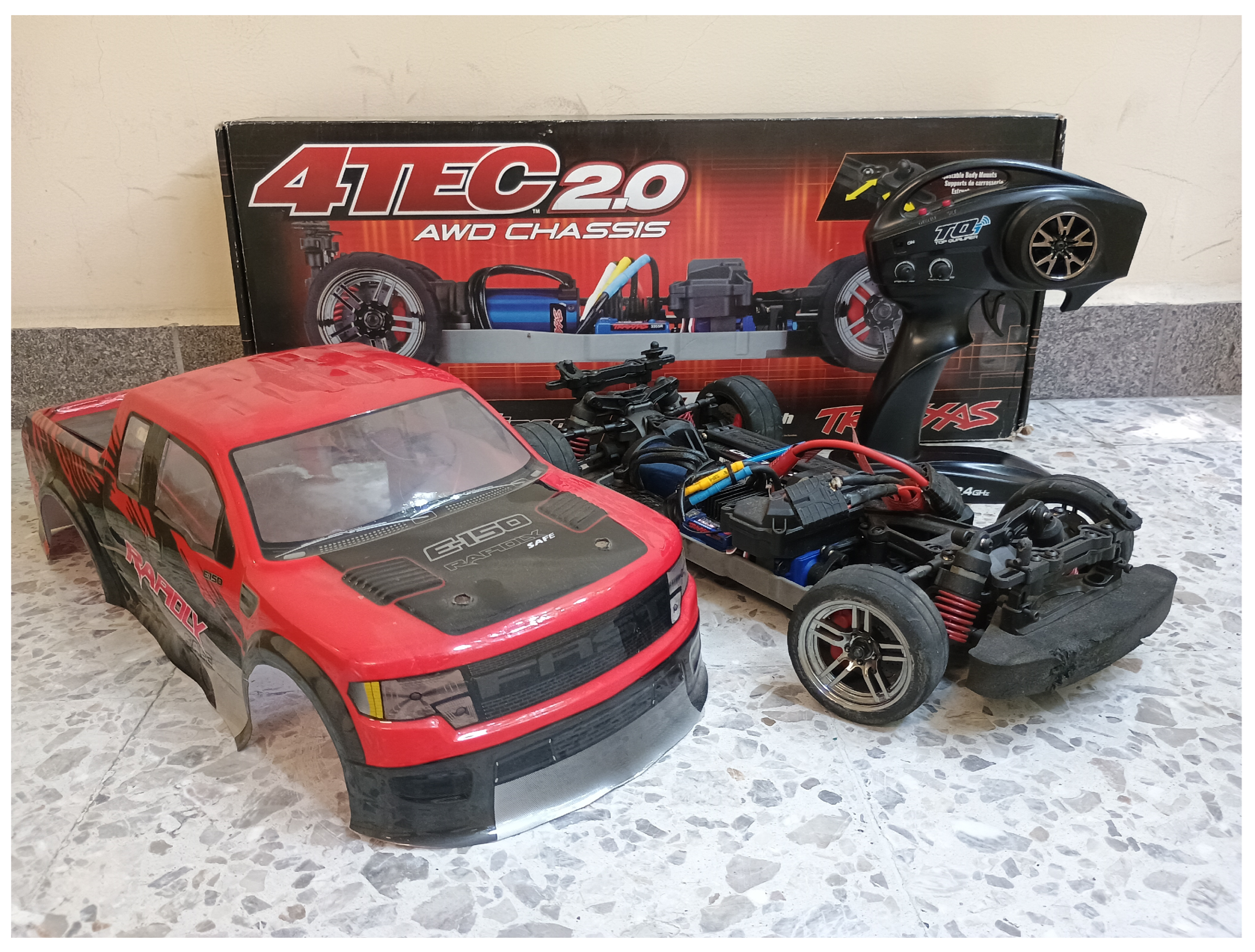
Figure 2.
Docking platform and 1:10 scale model of an electric vehicle coupled.
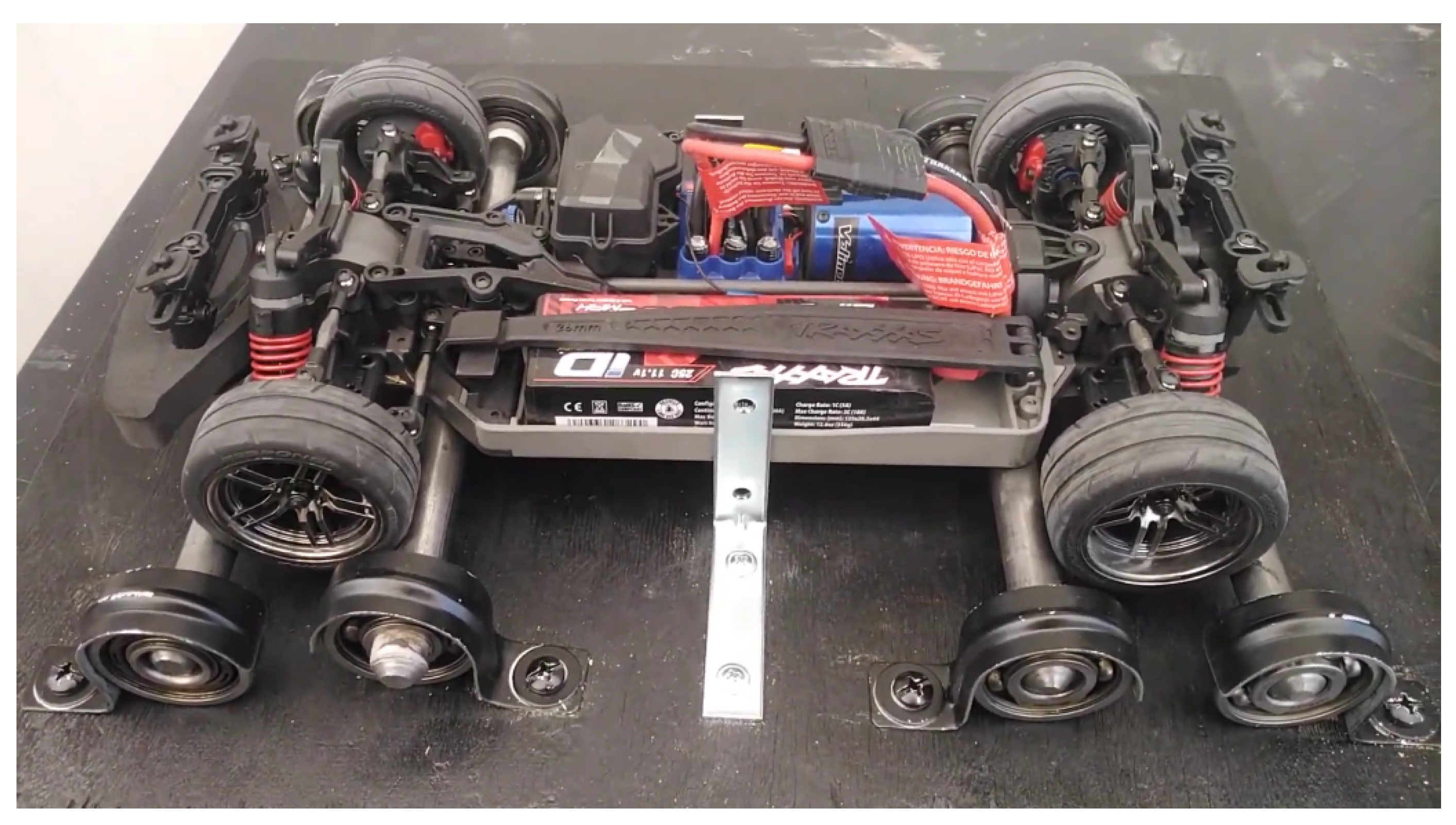
Figure 3.
Schematic diagram for the docking platform to conduct experiments using a 1:10 scale model of an electric vehicle.
Figure 3.
Schematic diagram for the docking platform to conduct experiments using a 1:10 scale model of an electric vehicle.
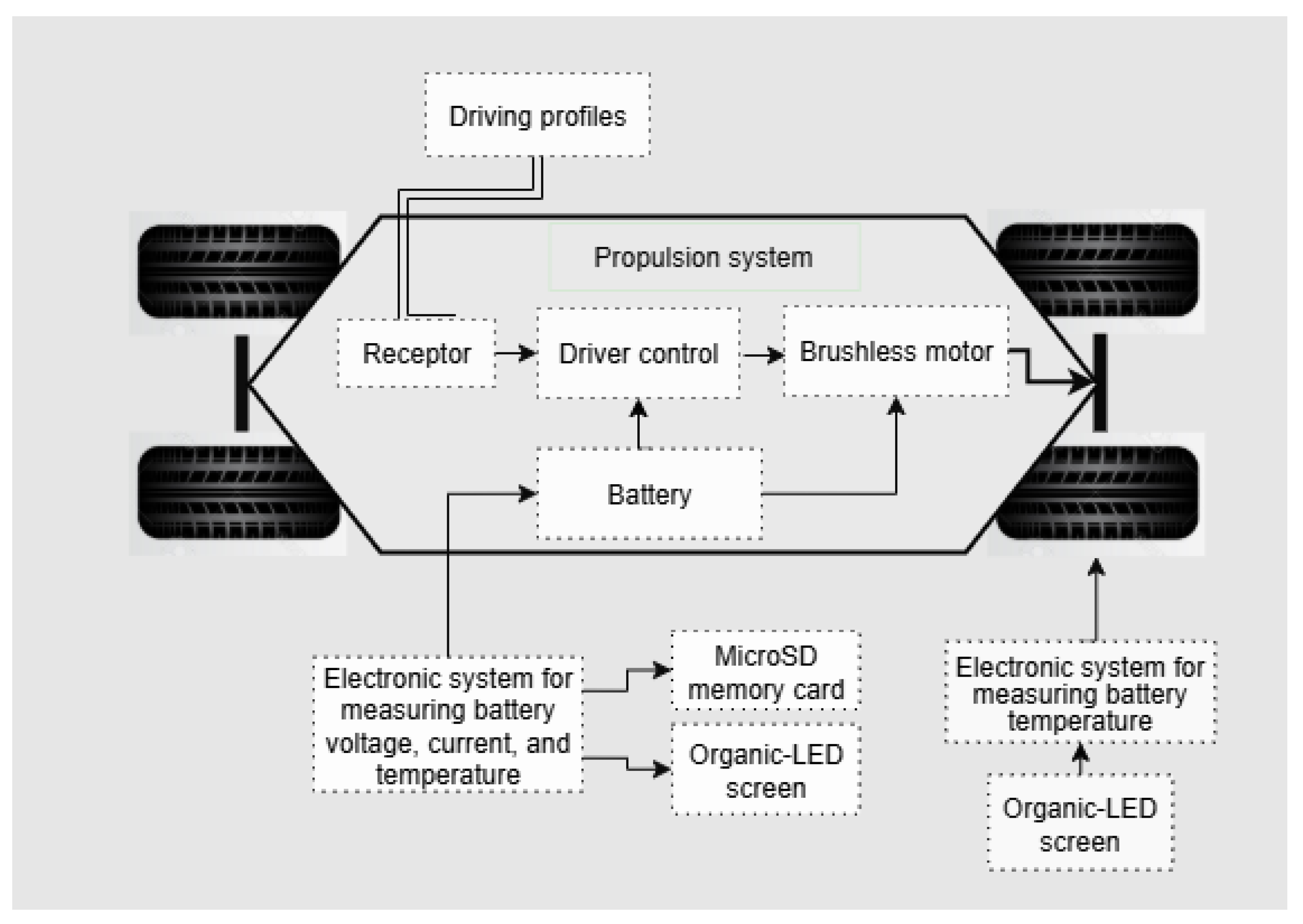
Figure 4.
Interest variables of the battery of the electric vehicle when Driving Profile A was used in a 36-minute experiment.
Figure 4.
Interest variables of the battery of the electric vehicle when Driving Profile A was used in a 36-minute experiment.
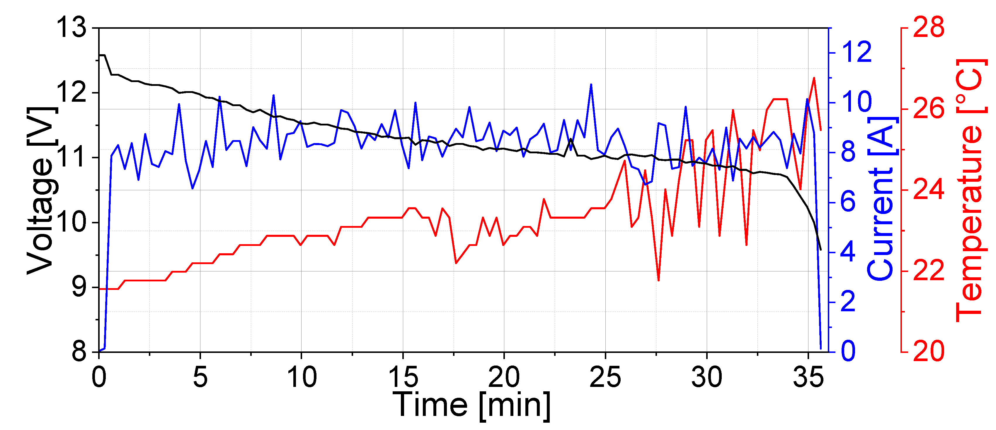
Figure 5.
Behavior of the battery SOC using Driving Profile A.
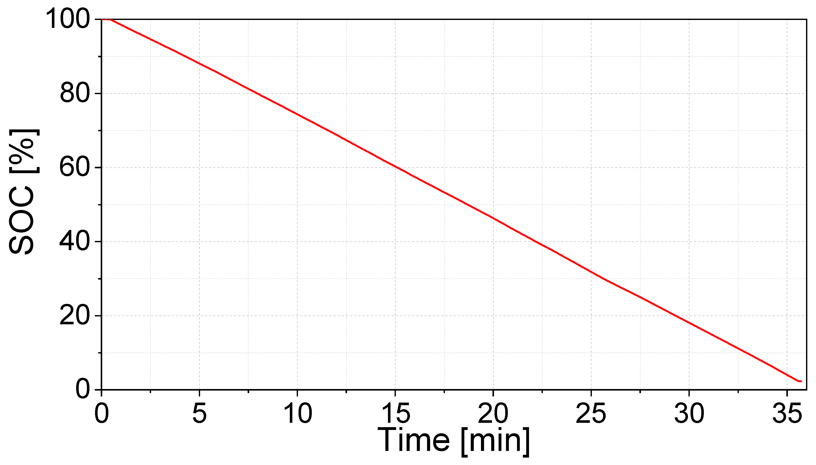
Figure 6.
Interest variables of the vehicle battery when Driving Profile B was used during a 40-minute experiment.
Figure 6.
Interest variables of the vehicle battery when Driving Profile B was used during a 40-minute experiment.
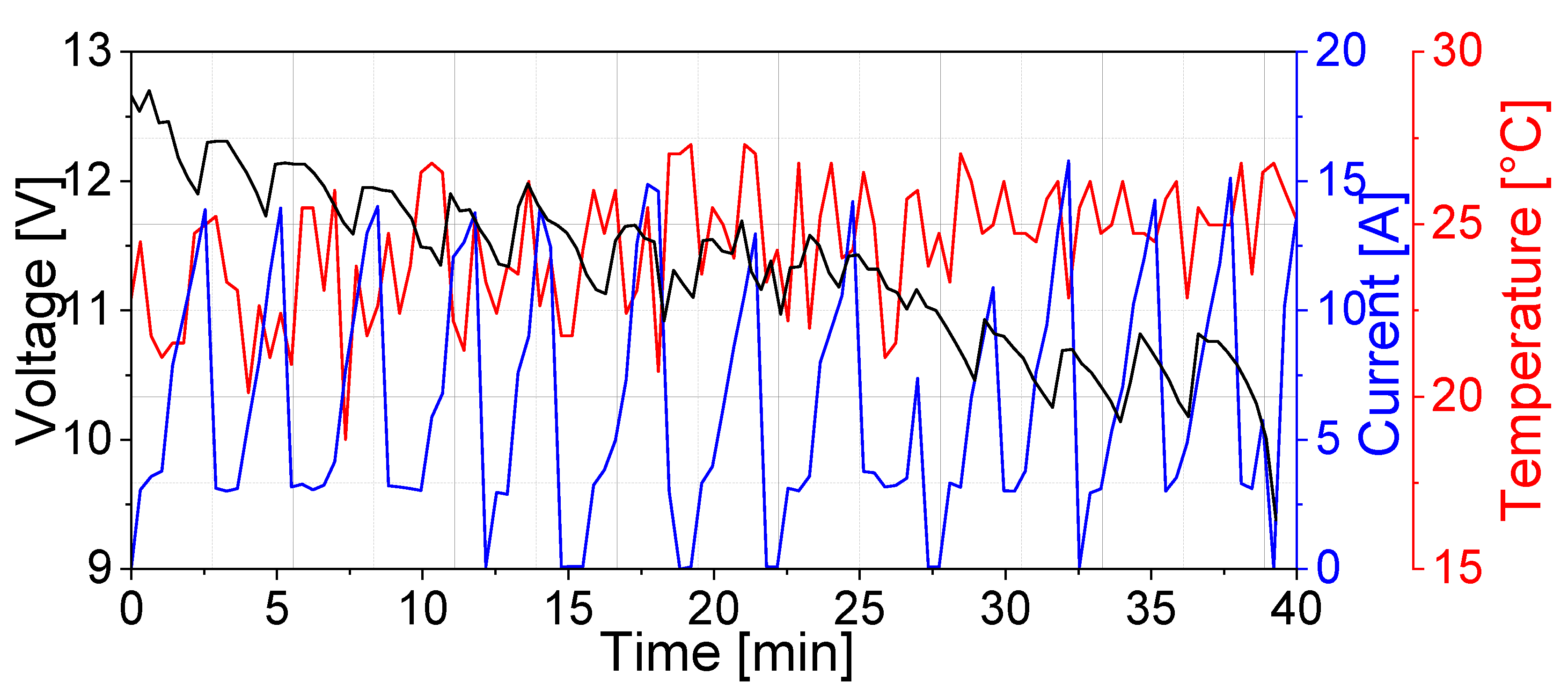
Figure 7.
Behavior of the SOC of the battery using Driving Profile B.
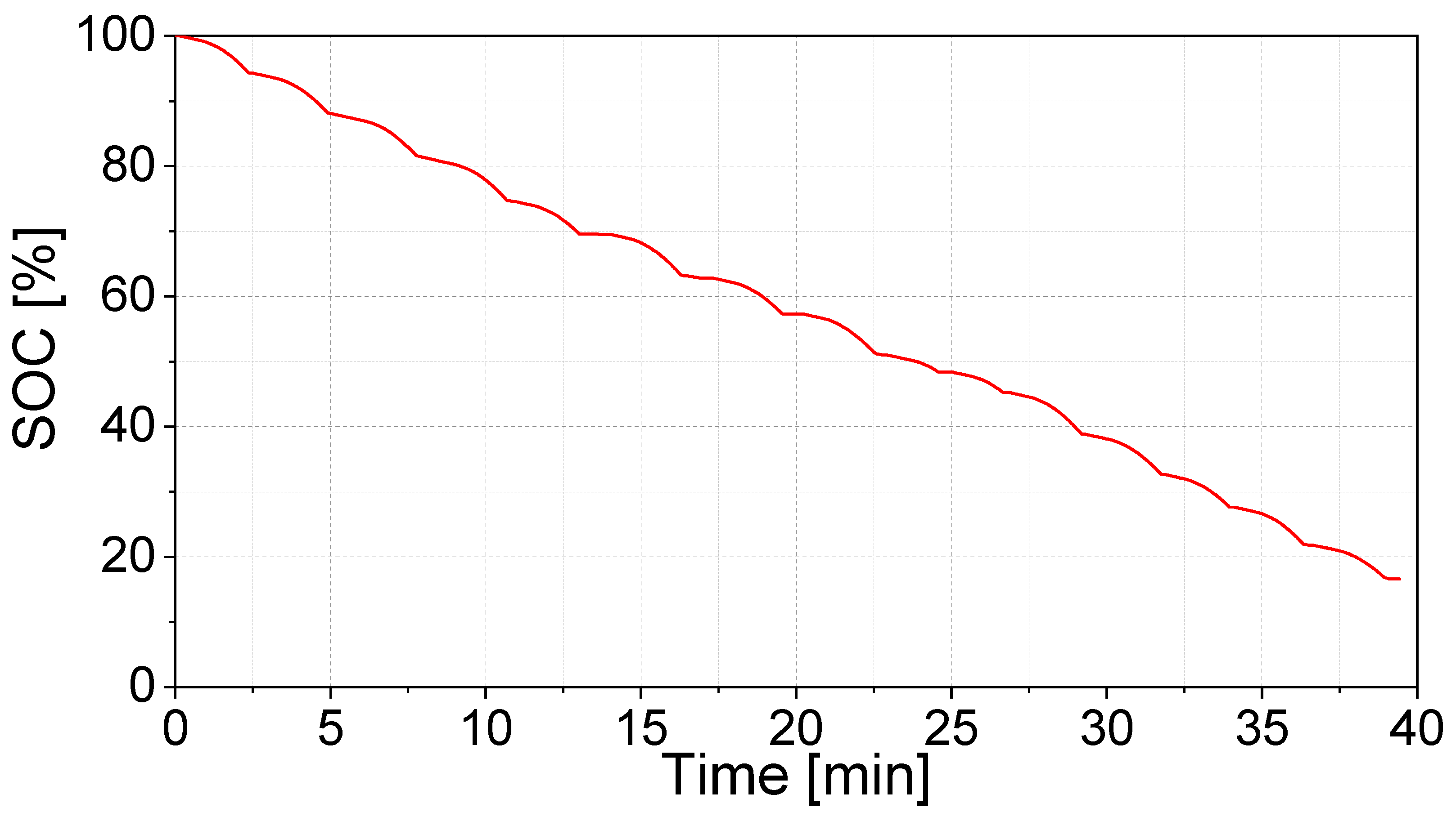
Figure 8.
Interest variables of the vehicle battery when Driving Profile C was used during a 40-minute experiment.
Figure 8.
Interest variables of the vehicle battery when Driving Profile C was used during a 40-minute experiment.
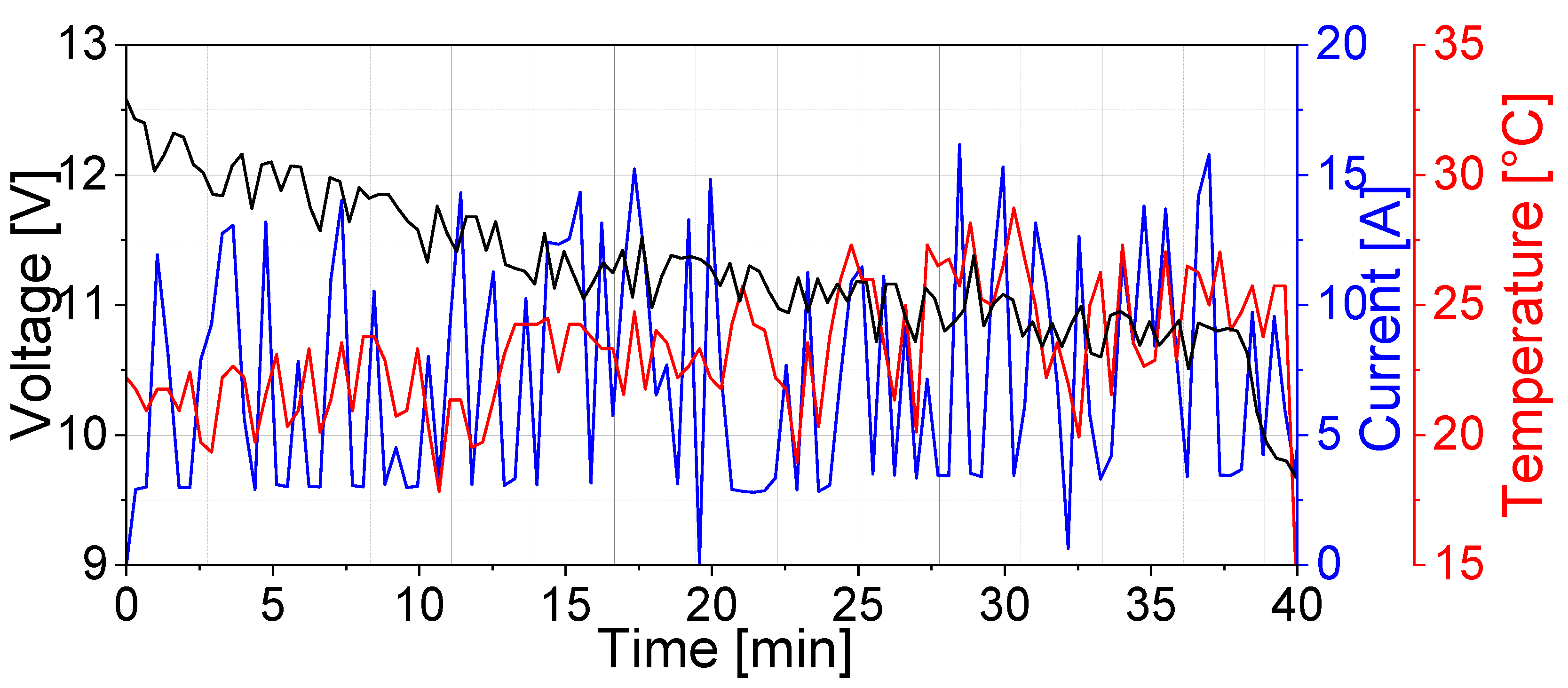
Figure 9.
Behavior of the battery SOC using Driving Profile C.
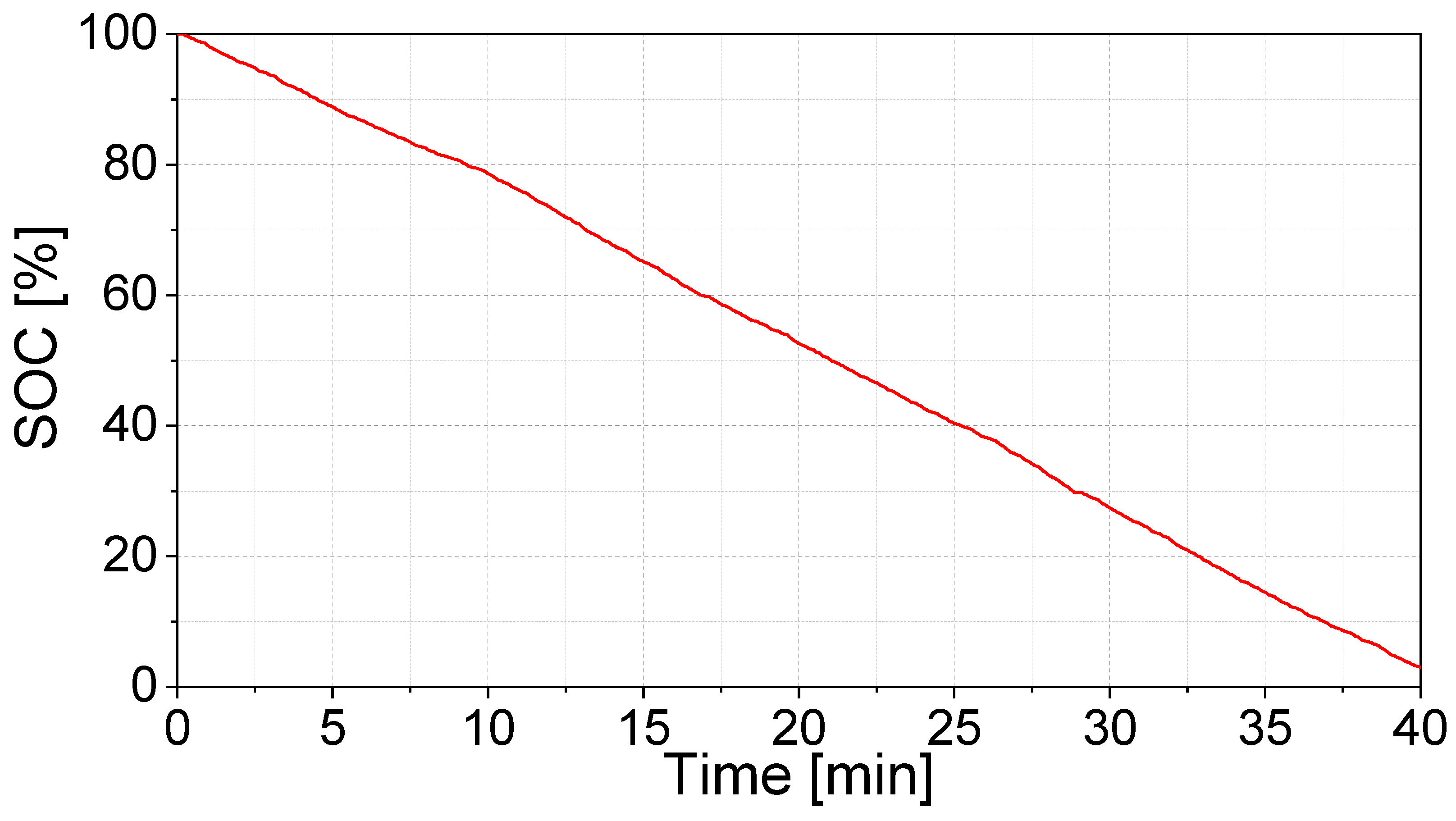
Figure 10.
Configuration of microturbine based on a wind vane vertically oriented. Image taken from https://www.amazon.com.mx when the seller is Astyer-X and the manufacturer is FTVogue.
Figure 10.
Configuration of microturbine based on a wind vane vertically oriented. Image taken from https://www.amazon.com.mx when the seller is Astyer-X and the manufacturer is FTVogue.
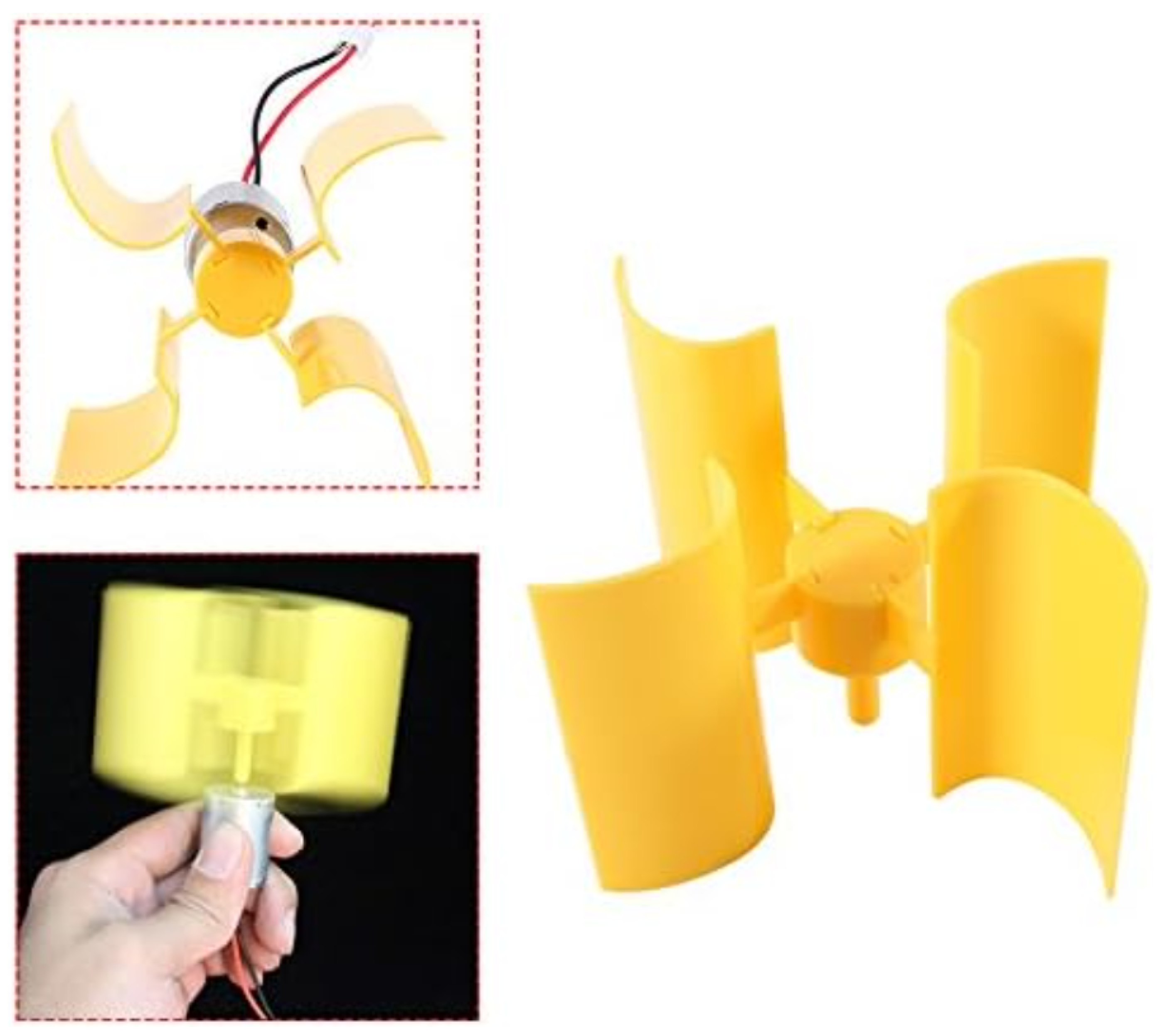
Figure 11.
Instantaneous power consumed by the 1:10 scale model of the electric vehicle.
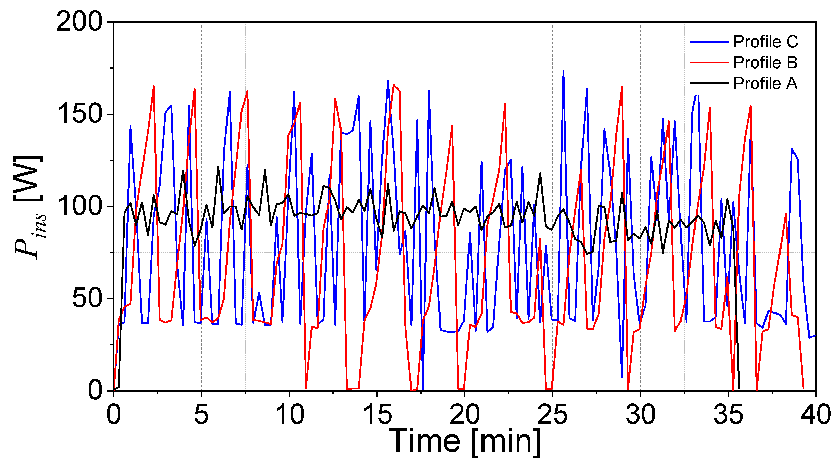
Figure 12.
Power produced by microturbine considering the three driving profiles.
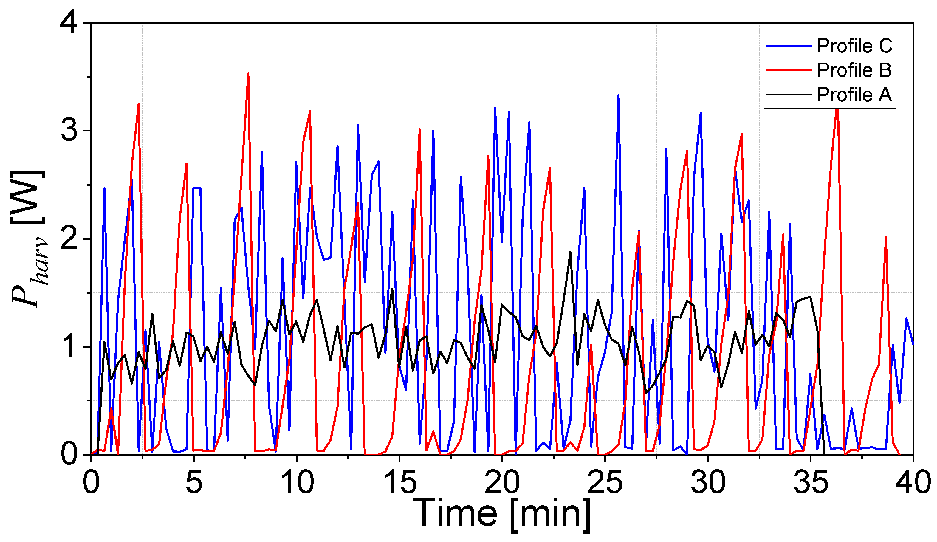
Figure 13.
Power produced by microturbine considering the three driving profiles.
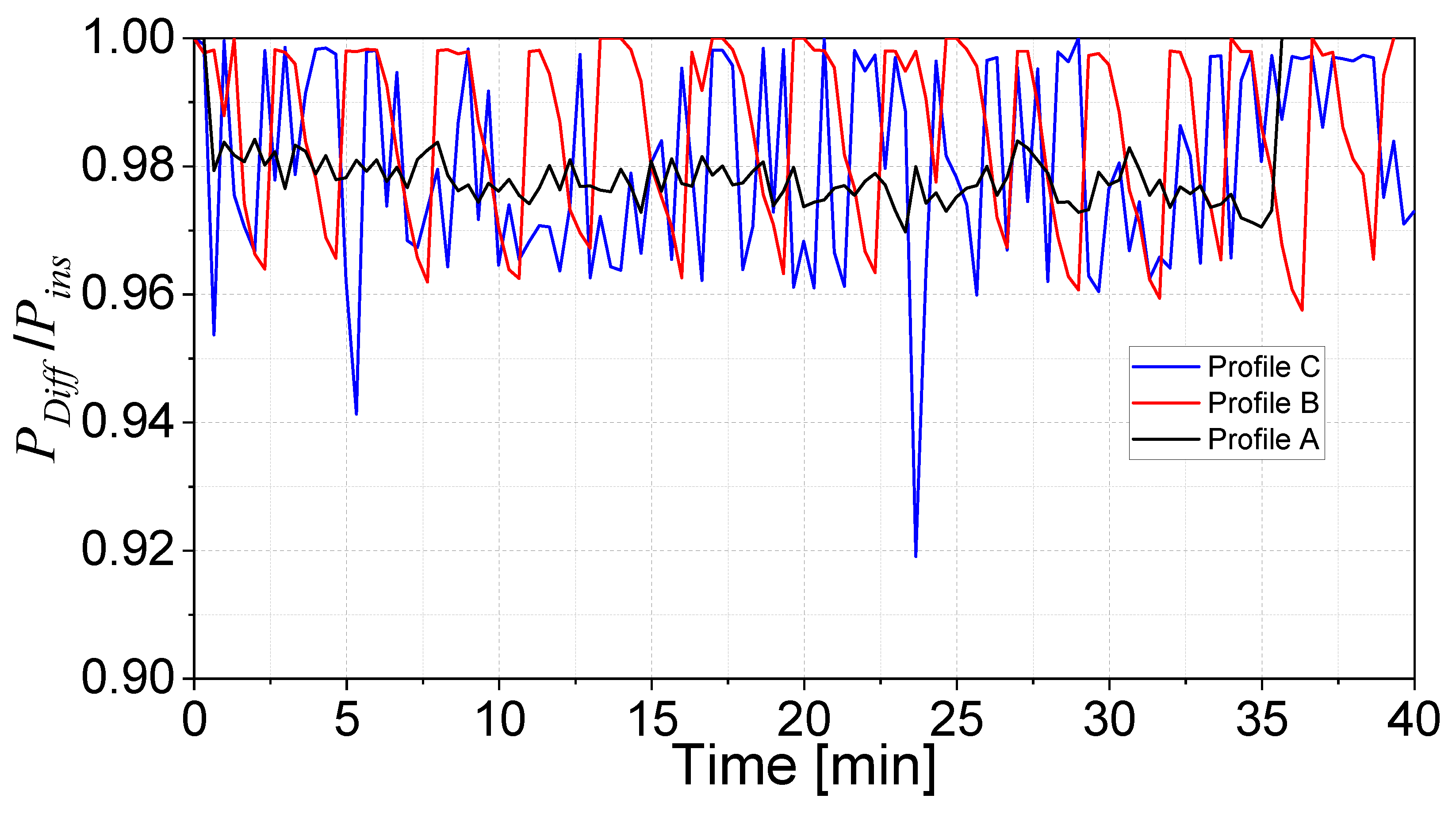
Figure 14.
Behavior for n when the three driving profiles are considered.
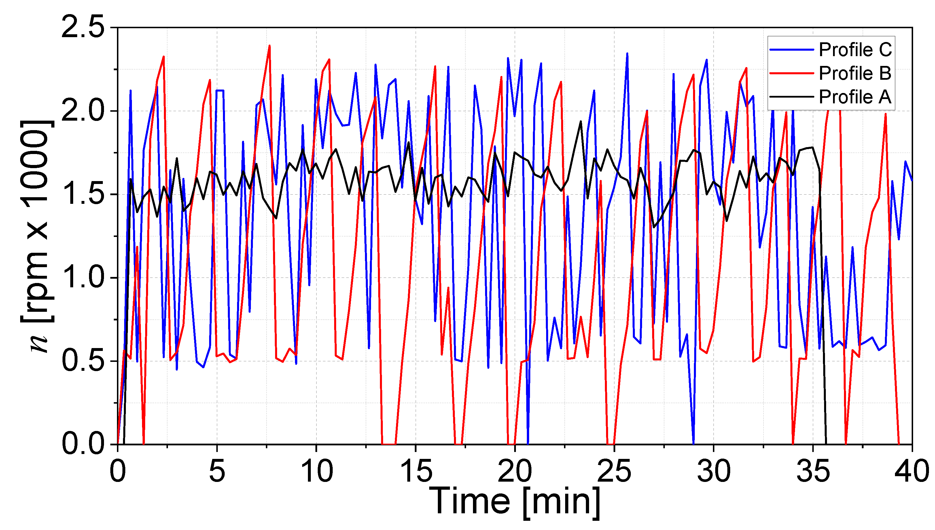

Table 1.
Features comparison between energy harvesters and lithium batteries.
| Feature | Energy harvester | Lithium-Ion batteries |
|---|---|---|
| Power output | Very low, milli and micro watts. | High, enough for application. |
| Energy source | Ambient, intermittent, and unpredictable. | Self-contained chemical energy. |
| Longevity | As long as the energy source is present. | Life limited by charge-discharge cycles. |
| Applications | Wireless sensors, medical implants, and wearable devices. | Smartphones, laptops, and electric vehicles. |
Table 2.
Comparison of the results considering the three driving profiles.
| Parameter | Profile A | Profile B | Profile C |
|---|---|---|---|
| SOC (%) | 80.00 | 80.00 | 80.00 |
| Time (min) | 7.95 | 9.16 | 9.30 |
| Voltage (V) | 11.94 | 11.88 | 11.61 |
| Mean current (amp) | 8.20 | 6.34 | 7.26 |
| Vehicle average speed (km/h) | 30.00 | 40.00 | 54.00 |
| Traveled distance (km) | 3.98 | 6.10 | 8.36 |
Table 3.
Comparison of the results considering the three driving profiles.
| Parameter | Profile A | Profile B | Profile C |
|---|---|---|---|
| [number of devices] | 98 | 118 | 89 |
| Vehicle average speed [km/h] | 29.62 | 21.00 | 24.56 |
| [W] | 1.03 | 0.85 | 1.13 |
Table 4.
Energy consumption in an electric vehicle according to the U. S. EPA related to fuel economy information [56,57].
| Usage and losses | City & highway | City | Highway |
|---|---|---|---|
| Charging battery | 10% | 10% | 10% |
| Auxiliary electric | 0-4% | 0-6% | 0-2% |
| Energy to wheels | 65-69% | 60-66% | 71-73% |
| Electric drive system | 18% | 20% | 15% |
| Accessories | 3% | 4% | 2% |
| Idle | 0% | 0% | 0% |
| Energy recovered from regenerative braking | 22% | 34% | 6% |
Disclaimer/Publisher’s Note: The statements, opinions and data contained in all publications are solely those of the individual author(s) and contributor(s) and not of MDPI and/or the editor(s). MDPI and/or the editor(s) disclaim responsibility for any injury to people or property resulting from any ideas, methods, instructions or products referred to in the content. |
© 2025 by the authors. Licensee MDPI, Basel, Switzerland. This article is an open access article distributed under the terms and conditions of the Creative Commons Attribution (CC BY) license (https://creativecommons.org/licenses/by/4.0/).
Copyright: This open access article is published under a Creative Commons CC BY 4.0 license, which permit the free download, distribution, and reuse, provided that the author and preprint are cited in any reuse.


