
Submitted:
05 September 2025
Posted:
09 September 2025
You are already at the latest version
Abstract
Stable adhesion on non-magnetic, steep, and irregular underwater surfaces (e.g., concrete dams with cracks or biofilms) remains a challenge for inspection robots. This study proposes a Venturi-ejector composite suction cup synergizing a rigid base with a dual-layer EPDM sponge seal (closed-cell + open-cell) for adaptive conformability. This design enables high-efficiency negative-pressure generation through hydrodynamic entrainment, overcoming limitations of traditional adsorption methods. Theoretical modeling established the quantitative relationship between adsorption force (F) and key parameters (nozzle/throat diameters, suction cup radius). CFD simulations revealed optimal adsorption at a nozzle diameter of 4.4 mm and throat diameter of 5.8 mm, achieving a peak simulated F of 520 N. Experiments demonstrated a maximum F of 403.1 N at 88.9 W power. The composite seal significantly reduced leakage on high-roughness surfaces (Ra≥6 mm) compared to single-layer designs. Integrated into an inspection robot, the system provided stable adhesion (>600 N per single adsorption device) on vertical walls and reliable operation under real-world conditions at Balnetan Dam, enabling mechanical-arm-assisted maintenance.
Keywords:
underwater inspection robot
; venturi-ejector
; composite suction cup
; adaptive sealing
; low-power adsorption
; non-magnetic surfaces
1. Introduction
Routine inspection and maintenance of underwater hydraulic structures (e.g., dams, reservoirs, intake structures) are paramount for the safe and efficient operation of hydropower projects. Underwater robots—remotely operated vehicles (ROVs) and autonomous underwater vehicles (AUVs)—have emerged as vital tools for performing these tasks, offering advantages in accessibility and reducing human risk. A critical requirement for many inspection tasks, particularly on vertical or steep surfaces, is the robot's ability to achieve stable adsorption to the substrate. This adhesion counteracts buoyancy, gravity, and hydrodynamic forces, enabling precise positioning and operation of onboard tools. However, achieving reliable adsorption presents significant challenges on common underwater infrastructure surfaces, which are typically non-magnetic (e.g., concrete, stone) and often irregular, rough, or biofouled.
To address this challenge, researchers domestically and internationally have proposed various adsorption solutions. Current primary adsorption methods for robots include thrust adsorption, biomimetic adsorption, magnetic adsorption, and negative pressure adsorption
Thrust adsorption presses the robot against the wall using thrust generated by propellers(Hachicha et al.,2019). For example, Mori et al.(2017)designed a wall-climbing robot with four thrusters. Chen et al.(2023) developed an underwater hull-cleaning robot that generates adsorption force via four vertical thrusters, each capable of a maximum thrust of 260 N. Commercial robots like HullWiper and ROVING BAT also favor thrust adsorption due to its straightforward implementation(Albitar et al.,2016).
Biomimetic adsorption mimics the adhesion mechanisms of organisms like geckos or ivy, utilizing microstructures or intermolecular forces for attachment(Krings et al.,2023;Chuang et al.,2017). For instance, Murphy et al.(2011) developed the Waalbot II wall-climbing robot employing gecko-inspired microcilia adhesive pads, enabling stable climbing on smooth or rough walls, including inverted surfaces. Xi et al.(2024) drew inspiration from the sealing ring structure formed by abalone pedal tentacle contraction, constructing multi-layer sealing rings at the suction cup base, enhancing adsorption force by 15.8% compared to a standard suction cup at 60% vacuum. Cong et al.(2021) emulated the microscopic groove structure on the fin surface of the Sichuan rock-climbing loach (Beaufortia kweichowensis), designing non-smooth groove morphologies on the suction cup working surface, achieving a 71.22% increase in maximum adsorption force on PMMA substrates compared to a standard suction cup.
Magnetic adsorption and negative pressure adsorption are currently the most widely used methods for underwater robots(Nguyen et al.,2021;Xinrui et al.,2021). Magnetic adsorption typically utilizes permanent magnets or electromagnets to generate adhesion. While offering high force-to-weight ratios, this technique is only applicable to ferromagnetic materials. For example, Lee et al.(2013) designed the Gunryu III robot, achieving energy-efficient and stable climbing on steel structures using permanent magnet adsorption. Stepson et al.(2017)developed a novel magnetic-wheel wall-climbing robot based on a Halbach permanent magnet array for efficient and safe hull inspection. Negative pressure adsorption can be further categorized into contact and non-contact types. Contact negative pressure adsorption creates a vacuum sealed region by pumping out fluid, relying on the pressure differential for adhesion(Koo et al.,2013). For example, Souto et al.(2013) proposed the Lappa robot, which generates a negative pressure differential within a sealed cavity for attachment. Nassiraei et al.(2012) developed a similar suction cup for an underwater cleaning robot. By integrating thrusters with cleaning brushes, they achieved a compact robot structure obtaining 52 N of adsorption force. Based on different hydrodynamic principles, non-contact negative pressure adsorption can be subdivided into two distinct technical pathways: One pathway utilizes the vortex effect, inducing a high-speed rotating flow field within the suction cup cavity to form a low-pressure vortex core at the center via centrifugal force (Zhu et al.,2020). For example, Liu et al.(2018) proposed pump-suction and impeller-type adsorption structures belonging to this category. The other pathway leverages the Bernoulli principle, generating a high-speed outer flow layer between the suction cup and the wall, where increased fluid velocity leads to reduced static pressure(Chen et al.,2022;Ferreira et al., 2018;). For instance, Sakagami et al.(2013) developed a wall-climbing robot by adding a negative pressure effect plate around a propeller. Guo et al.(2022) designed a hull-cleaning robot using contra-rotating propeller technology. Both designs are based on the Bernoulli principle and demonstrated good performance in actual ship trials.
Nevertheless, the aforementioned methods still face common limitations in practical applications: Thrust adsorption suffers from high power consumption and limited payload capacity; biomimetic adsorption involves complex fabrication processes and is prone to contamination; magnetic adsorption is restricted by material limitations; and negative pressure adsorption is sensitive to wall sealing integrity. Consequently, facing the inspection demands of large hydraulic structures with high loads and complex unstructured surfaces, there is an urgent need for a novel underwater adsorption mechanism that simultaneously achieves "strong adsorption force, low energy consumption, and broad adaptability".
The Venturi ejector, owing to its "zero-mechanical-vacuum-pump" fluid entrainment characteristics, has demonstrated efficient negative pressure generation capabilities in fields such as chemical engineering(Xu et al.,2016;Ma et al.,2023) and environmental protection(Zu et al.,2024;Feng et al.,2024). Its core advantages lie in its extremely simple structure, rapid response, low sealing requirements, and ability to form a stable negative pressure zone within milliseconds through jet-entrainment synergy. However, its potential for adhesion on underwater, non-magnetic, irregular walls remains largely unexplored. Addressing this gap, this paper proposes an integrated "Venturi effect-composite suction cup" adhesion system for dam inspection. The innovation of this system lies not only in the suction cup itself but also in its cross-scale synergistic design: The composite suction cup, comprising a rigid base and a flexible sponge layer, ensures both structural strength and adaptive conformity to surface topography; The deep coupling of the submersible pump with the ejector enables dual functions—high-pressure jet driving and negative pressure entrainment—through a single power source; The integrated fluid-structure-control architecture allows the system to provide stable adsorption force on the order of hundreds of Newtons on complex dam surfaces (cracks, exposed aggregate, biofilm) while consuming only around 100 Watts.
The remainder of this paper is structured as follows: Section 2 details the structural design of the Venturi-effect-based composite suction cup and establishes a theoretical model for predicting adsorption force. Section 3 presents the Computational Fluid Dynamics (CFD) simulations conducted to analyze flow field characteristics and optimize key geometric parameters (nozzle diameter, throat diameter, suction cup diameter), followed by a discussion of the results. Section 4 describes the physical experiments performed to validate the theoretical and simulation findings, including laboratory adsorption force tests and field testing on an actual dam surface. Finally, Section 5 summarizes the main conclusions and outlines future work directions.
2. Structural Design and Theoretical Analysis
This section addresses the core challenge of achieving stable adsorption on steep, non-magnetic, and potentially rough underwater surfaces. To this end, a novel composite suction cup structure is proposed, integrating a rigid base for structural integrity, a flexible sponge layer for adaptive sealing on irregular surfaces, and a Venturi ejector driven by a submersible pump for efficient negative pressure generation. The primary goal of the structural design is to combine high adsorption strength with adaptability. To precisely predict the performance of this mechanism and guide its optimization, a mathematical model based on fluid dynamics principles is established to calculate the adsorption force.
2.1. Structural Design
Figure 1a illustrates the three-dimensional model of the underwater inspection robot adsorption device, integrating a support arm, reinforcement arm, buoyancy material, control system and the complete adsorption system. Figure 1b isolates the adsorption system, whose core components include the submersible pump, nozzle, suction chamber, diffuser, pipeline, rigid suction cup and a dual-layer adaptive sealing assembly consisting of closed-cell EPDM sponge and open-cell EPDM sponge - providing structural rigidity while ensuring superior conformance to irregular surfaces.
As shown in Figure 2, when the adhesion system approaches the rough concrete dam surface, the submersible pump generates high-pressure water flow. Accelerated by the ejector nozzle, this flow becomes a high-speed jet entering the throat and suction chamber. Significant hydrodynamic effects follow. The jet's kinetic energy surge causes a sharp pressure drop at the nozzle exit, creating a local low-pressure zone. Simultaneously, the high-speed fluid, via viscous shear and turbulent entrainment, drives the suction chamber fluid out, efficiently evacuating the suction cup to form a stable negative pressure cavity.
Once the negative pressure cavity forms, the suction cup adheres tightly to the dam surface due to the pressure differential. The composite suction cup's rigid disc ensures structural stability, while the dual-layer sponge assembly provides graded deformation and sealing:
The outer open-cell EPDM sponge, with its high compressibility and interconnected pores, readily conforms to macro-scale surface irregularities and depressions through material flow and pore collapse.
The inner closed-cell EPDM sponge, offering greater structural integrity and elastic recovery, effectively compensates for micro-scale roughness and provides uniform pressure distribution.
This hierarchical structure creates a multi-scale sealing barrier that dynamically adapts to the surface topography, effectively blocking water ingress across diverse and irregular underwater surfaces.
The differential compressibility and mechanical behavior of the two layers enable progressive adaptation. The softer, more compliant open-cell layer absorbs significant variations first, while the stiffer closed-cell layer maintains structural support and ensures consistent sealing pressure. As the seal conforms intimately to the surface asperities, internal fluid exchange diminishes, stabilizing the negative pressure. This creates a lasting adhesion force between the mechanism and the dam, enabling high-strength, stable adhesion on complex and rough engineering surfaces through this mechanical equilibrium.
2.2. Theoretical Analysis
A mathematical model of the adsorption mechanism is established as shown in Figure 3. Here, r represents the radius of the ejector tube, R is the radius of the suction cup of the adsorption mechanism, and D1 to D7 correspond to the diameters of the seven transition sections of the ejector. During the operation of the adsorption mechanism, water flows out at high speed from the nozzle of the ejector and enters the throat and suction chamber. Under the Venturi effect, the fluid inside the suction cup is efficiently drawn out. Once the negative pressure stabilizes, the fluid inside the suction cup is considered to be in a static state.
1) The actual flow velocity v
To determine the negative pressure at the throat, it is necessary to calculate the water flow velocity at the ejector inlet, which is influenced by the pump's head H and exit velocity v, typically exhibiting a nonlinear relationship as follows:
where a and b are empirical coefficients specific to the pump.
When the pump is connected to the adsorption system, the total hydraulic resistance loss of the system is given by:
Here,hw denotes the total hydraulic resistance loss, hj represents the local resistance loss, and hf signifies the frictional resistance loss along the pipeline.
The local resistance loss can be calculated as:
where v0 represents the velocity at the transition section, ζ is the local resistance coefficient, and g is the acceleration due to gravity (9.8 m/s2).
Thus, the total local resistance loss is:
Here, hj1 to hj6 represent the local resistance losses at different sections, and A1 to A7 are the areas of the seven transition sections, calculated as A = πD2/4, with v being the velocity at the inlet.
The frictional resistance loss along the pipeline is:
where λ is the friction factor, and l is the length of the piping system.
According to the principle that the system's hydraulic loss equals the pump's head,
By substituting equations (1) to (5) into equation (6), the ejector inlet velocity v can be calculated.
2) Negative Pressure in the Suction Chamber p4
Since sections Ⅰ and Ⅳ are at the same elevation and the frictional resistance loss between them is negligible, applying the Bernoulli equation between these two sections yields:
By solving equations (1), (3), and (8) simultaneously, the negative pressure p4 at the throat (section Ⅳ) can be determined.
3) Adsorption Force F of the Adsorption Mechanism
Given that the height difference between the suction chamber and the interior of the suction cup is negligible, the negative pressure p4 in the suction chamber is equivalent to the average negative pressure inside the suction cup. Therefore, the adsorption force F generated by the adsorption mechanism is:
where S represents the effective area subjected to force, in mm2.
By substituting equations (3) to (9) into equation (10), the final expression for the adsorption force F is obtained. These analytical relationships provide the basis for the parametric CFD study presented in Section 3.
3. CFD Simulation and Parametric Study Results
This section details the Computational Fluid Dynamics (CFD) methodology employed to analyze the flow dynamics within the Venturi-Ejector Composite Suction Cup (VECSC) and presents the results of the parametric study investigating the influence of key geometric parameters (d, a, b) on the adsorption force F. The goal is to understand the underlying mechanisms, validate the theoretical model, and identify optimal conFigureurations.
3.1. Simulation Model Setup
Based on the theoretical analysis of the adsorption force, the key parameters affecting the adsorption force F include the pump flow velocity v and head H, the ejector nozzle diameter a, the ejector throat diameter b, and the suction cup inner diameter d. The pump flow velocity v and head H together determine the pressure and velocity at the ejector inlet. An increase in these parameters can significantly enhance the negative pressure in the suction chamber. In this study, a submersible pump with a characteristic curve of H =18- 2.909v2(100 W power) was selected. The selection of the spray nozzle diameter a requires a balance between flow loss and the Bernoulli effect: a nozzle that is too small can lead to an increase in the local resistance coefficient, thereby reducing the inlet velocity and weakening the negative pressure generation. Conversely, a nozzle that is too large can weaken the Bernoulli effect, similarly reducing the negative pressure. The throat diameter b has the following effects: a throat that is too small can increase local resistance and reduce the inlet velocity, while a throat that is too large can result in insufficient vacuum in the suction chamber. The suction cup radius r directly determines the area over which the negative pressure acts. A radius that is too small may result in insufficient adsorption force to meet the stability requirements for underwater robot operations, while a radius that is too large is constrained by the overall structural dimensions.To systematically quantify the influence of each parameter on the adsorption force, this study designed the parameter combination scheme shown in Table 1 for multi-condition numerical simulations.
3.2. Boundary Condition Setup and Meshing
A three-dimensional, steady-state CFD simulation was performed using the Fluent solver (Ansys 2022 R1) to capture the internal flow field within the Venturi-based adsorption structure. The computational domain was confined strictly to the fluid region, comprising the ejector, suction-cup cavity, and connecting pipelines, as illustrated in Figure 4a. The incompressible Navier–Stokes equations were solved in conjunction with the RNG k–ε turbulence model, the latter being selected for its proven accuracy in flows dominated by swirl and high strain rates. Enhanced wall treatment was activated to ensure reliable resolution of the near-wall boundary layer.
Pressure–inlet and pressure–outlet conditions were imposed at the domain inlet and outlet, respectively. The inlet pressure was dynamically linked to the experimental pump characteristic curve H=18-2.909v2 via a User-Defined Function (UDF). All solid boundaries were treated as no-slip walls. The coupled pressure–velocity scheme was employed, with PRESTO! discretisation for pressure, second-order upwind for momentum, and first-order upwind for turbulent kinetic energy and dissipation rate; gradients were recon-structed using the least-squares cell-based method.
A hybrid mesh of tetrahedra, prisms, and pyramids was generated in Fluent Meshing, with boundary-layer inflation applied in the nozzle contraction, throat, diffuser, and suction chamber to satisfy the turbulence model’s y+ requirements. A grid-independence study was conducted by sequentially refining the mesh from 0.5 M to 1.2 M elements. The static pressure monitored at the throat centre varied by only 0.4 % between the 0.8 M and 1.2 M cases, confirming that the latter (≈ 1.2 M cells) achieves an acceptable compromise between accuracy and computational cost. Convergence was declared when the continuity and momentum residuals fell below 10−5 and the back-flow area fraction at the outlet stabilized at 29.3 %, ensuring solution robustness.
3.3. Effect of Suction Cup Inner Diameter on Adsorption Force
In the design of underwater robot adsorption systems, the inner diameter of the suction cup significantly impacts the adsorption force. This study analyzed the relationship between the suction cup's inner diameter and the adsorption force under conditions where the ejector nozzle diameter (a) was 3 mm and the throat diameter (b) was 4.8 mm.
As shown in Figure 5, the adsorption force exhibits an upward trend as the inner diameter of the suction cup increases. This is due to the direct increase in the effective negative pressure area caused by the enlargement of the suction cup's inner diameter. A larger effective area can generate a stronger adsorption force. However, a larger inner diameter is not always better. Once the inner diameter exceeds a certain range, the risk of leakage increases significantly. This not only reduces the adsorption efficiency but can also lead to adsorption failure. For contact negative pressure adsorption, this balance is particularly crucial. If the inner diameter of the suction cup is too small, it becomes difficult to generate sufficient adsorption force to meet the stability requirements for underwater robot operations. Conversely, if the inner diameter is too large, sealing issues can cause the adsorption force to become unstable. Taking into account both the adsorption force and system stability, subsequent research primarily focuses on analyzing and discussing scenarios where the suction cup's inner diameter is 80 mm.
3.4. Effects of Ejector Nozzle Diameter on Adsorption Force
This study delves into the impact of the ejector nozzle diameter, a critical parameter, on the adsorption force. Based on the established simulation model, the study analyzed the effects of varying nozzle diameters (3.0, 3.3, 3.5, 3.7, 4.0, 4.2, 4.4, 4.6 mm) while maintaining a constant throat diameter of 5.2 mm.
Figure 6 illustrate the pressure cloud diagrams and axial pressure curves at different nozzle diameters. When the nozzle diameter is small, the pressure at the nozzle exit drops rapidly, creating a high negative pressure. This is due to the smaller nozzle diameter accelerating the fluid flow. According to Bernoulli's equation, the increase in flow velocity leads to a significant decrease in static pressure, thereby generating a stronger negative pressure effect within the suction cup. However, as the nozzle diameter gradually increases, the negative pressure effect diminishes. Specifically, the negative pressure increases with the nozzle diameter up to 4.0 mm, reaching a maximum value of 103.984 kPa. Beyond this point, further increases in nozzle diameter result in a gradual decrease in negative pressure.
Figure 7 further reveal the effects of nozzle diameter on fluid flow velocity. A smaller nozzle diameter intensifies the high-speed jet at the nozzle exit, driving the fluid within the suction chamber through viscous shear and turbulent entrainment. This efficiently evacuates the fluid from the suction cup, forming a stable negative pressure cavity. However, when the nozzle diameter is too large, the fluid velocity decreases, weakening the viscous shear and turbulent entrainment effects. This results in slower fluid renewal within the suction chamber, negatively impacting the formation of negative pressure.
As shown in Figure 8, the relationship between nozzle diameter and negative pressure, as well as adsorption force, exhibits a clear nonlinear trend. When the nozzle diameter is small, the significant increase in fluid flow velocity at the nozzle enhances the Bernoulli effect, generating a stronger negative pressure. However, due to the larger local resistance coefficient associated with the smaller nozzle diameter, the inlet velocity is reduced, weakening the Bernoulli effect and subsequently the negative pressure and adsorption force. As the nozzle diameter gradually increases, the local resistance coefficient decreases, the inlet velocity increases, and the Bernoulli effect strengthens, leading to an increase in negative pressure and adsorption force. Nevertheless, once the nozzle diameter reaches a certain threshold, the fluid velocity decreases, diminishing the Bernoulli effect and causing the negative pressure and adsorption force to decline. Therefore, there exists an optimal nozzle diameter that maximizes negative pressure and adsorption force.
3.5. Effects of Ejector Throat Diameter on Adsorption Force
This section maintains a constant nozzle diameter of 4.2 mm while varying the throat diameter (4.8, 5.0, 5.2, 5.4, 5.6, 5.8, 6.0, 6.2, 6.4 mm) to analyze its impact on adsorption force.
Figure 9 illustrate the pressure cloud diagrams and axial pressure curves at different throat diameters. As the throat diameter increases, the negative pressure at the nozzle exit gradually decreases. A smaller throat diameter effectively constrains fluid flow, maintaining higher fluid velocity and lower pressure within the throat, which is conducive to negative pressure formation and sustainment. However, an overly small throat diameter can restrict fluid flow, increasing local resistance losses and affecting smooth fluid movement.
Figure 10 depict the velocity cloud diagrams and axial velocity curves at different throat diameters. A smaller throat diameter sustains higher fluid velocity within the throat, effectively driving fluid motion within the suction chamber and forming a good fluid renewal effect. Conversely, a larger throat diameter reduces fluid velocity, weakening viscous shear and turbulent entrainment effects, which slow down fluid renewal within the suction chamber and negatively impact negative pressure formation and stability.
As shown in Figure 11, the relationship between throat diameter and negative pressure, as well as adsorption force, also exhibits a nonlinear trend. A smaller throat diameter effectively constrains fluid flow, maintaining higher fluid velocity and lower pressure within the throat, which is favorable for negative pressure formation and sustainment. However, due to the larger local resistance coefficient associated with the smaller throat diameter, the inlet velocity is reduced, weakening the Bernoulli effect and subsequently the negative pressure and adsorption force. As the throat diameter gradually increases, the local resistance coefficient decreases, the inlet velocity increases, and the Bernoulli effect strengthens, leading to an increase in negative pressure and adsorption force. Once the throat diameter reaches a certain threshold, however, fluid velocity decreases, diminishing the Bernoulli effect and causing negative pressure and adsorption force to decline. Therefore, there exists an optimal throat diameter that maximizes negative pressure and adsorption force
3.6. Synergistic Effects of Ejector Nozzle and Throat Diameters on Adsorption Force
To comprehensively evaluate the performance of the ejector, this study further investigates the combined effects of nozzle and throat diameters. Figure 12a,b illustrate the effects of nozzle-throat diameter combinations on negative pressure and adsorption force, respectively. The results indicate that different combinations of nozzle and throat diameters significantly influence negative pressure and adsorption force. Smaller combinations of nozzle and throat diameters can generate higher negative pressure at the nozzle exit, thereby producing a stronger adsorption force. This is because the smaller nozzle diameter accelerates fluid flow, while the smaller throat diameter effectively constrains fluid flow, maintaining higher fluid velocity and lower pressure within the throat. The combined action of these two factors facilitates negative pressure formation and sustainment.
Specifically, when the nozzle diameter is 4.4 mm and the throat diameter is 5.8 mm (combination a4.4b5.8), the negative pressure simulation value reaches 108.966 kPa, with a corresponding adsorption force of 520 N, representing the optimal adsorption performance in this study. However, when the nozzle and throat diameters exceed a certain range, the adsorption force begins to decline. This is attributed to the fact that overly small nozzle or throat diameters increase local resistance losses, reducing inlet velocity and weakening the Bernoulli effect, thereby generating smaller negative pressure and adsorption force. Similarly, when the nozzle or throat diameter is too large, fluid velocity decreases, weakening the Bernoulli effect and subsequently reducing negative pressure and adsorption force. Therefore, optimizing the combination of nozzle and throat diameters is crucial for enhancing ejector performance. By appropriately matching nozzle and throat diameters, it is possible to achieve a significant fluid velocity and Bernoulli effect with minimal resistance loss, thereby realizing optimal adsorption performance.
4. Performance Experiment
4.1. Experimental Setup
To validate the CFD optimization conclusions from Section 3.6 and comprehensively evaluate the operational performance of the designed adsorption structure, an integrated experimental platform was meticulously constructed (Figure. 13b). The platform design strictly followed the nozzle-throat synergy optimization results(Section 3.6, Figure. 12), with five representative parameter combinations (H1: a=3.0mm,b=5.0 mm;H2:a=3.5 mm,b=5.6 mm;H3: a=4.0 mm,b=5.8 mm; H4: a=4.4 mm,b=6.0 mm; H5: a=4.6 mm,b=6.2 mm) fabricated into physical ejector prototypes (Figure. 13c). The system comprised four core functional modules:
The adsorption force and negative pressure monitoring unit employed a high-precision dynamometer coupled with a DAQ system to synchronously capture adsorption force (F) and cavity pressure (p).
The surface adaptability validation module simulated real-world underwater engineering complexity using six typical structural surface specimens (Figure. 13a), including smooth cement blocks, grid-patterned surfaces, rough curved profiles, irregular granular textures, cracked concrete, and exposed aggregate substrates.
The sealing layer material comparison group investigated the impact of flexible seals on adsorption performance by testing three EPDM variants: open-cell EPDM (high compressibility), closed-cell EPDM (high elastic recovery), and a novel composite EPDM structure (closed-cell + open-cell bilayer, Figure 13d).
The power system utilized two submersible pumps (Q1: characteristic curve H=18−2.909v2, rated 100 W; Q2: H=13−4.727v2, rated 60 W), with measured average operating powers of 88.938 W and 60.507 W, respectively (Figure. 13e).
4.2. Simulation Model Validation
Figure 14 compares simulated and experimentally measured adsorption forces for the five ejector conFigureurations (H1–H5) under pump Q1. The results demonstrate a strong positive correlation (R>0.92) between simulated predictions and experimental data, validating the reliability of the CFD model and its efficacy in predicting adsorption performance. The maximum experimental adsorption force of 403.1 N (corresponding to cavity pressure ≈88 kPa) under the H3 conFigureuration was 22.5% lower than the simulated optimum of 520 N. This discrepancy is attributed to two primary factors: firstly, the actual operating power of the selected submersible system (88.9 W) was lower than its rated capacity (100 W), reducing kinetic energy driving the jet flow; secondly, additional turbulent dissipation occurred due to surface roughness in the metal fluid channels, further diminishing negative pressure generation efficiency. This finding indicates that while the CFD model effectively guides parameter optimization, a power loss correction factor (η≈0.85) should be introduced to improve prediction accuracy by accounting for real-world system losses.
4.3. Adsorption Performance
The relationship between adsorption force (F) and power consumption—core metrics for evaluating underwater adsorption devices—was quantified by comparing experimental results under different power sources. As illustrated in Figure 15, transitioning from the lower-power pump Q2 (60.5 W) to the higher-power pump Q1 (88.9 W) significantly enhanced the negative pressure (p) within the suction cup cavity and the resultant adsorption force (F). This trend was consistent across all tested ejector parameter sets (H1–H5), confirming that increased input power directly strengthens adsorption performance. Notably, under the CFD-optimized H3 conFigureuration (a=4.0 mm,b=5.8 mm), the Q1 pump achieved a peak adsorption force of 403.1 N (corresponding to p=88 kPa), markedly exceeding the 349.1 N (p=77 kPa) obtained with Q2, thereby quantifying the decisive impact of input power intensity on adsorption capability.
The adaptability of the adsorption device to complex underwater engineering surfaces is critical for practical applications. To evaluate this, three flexible sealing materials with distinct mechanical properties—open-cell EPDM, closed-cell EPDM, and composite EPDM—were systematically tested on six representative structural surfaces (Figure 13a) using the optimized H1 conFigureuration and Q1 power source (Figure 16). On low-roughness surfaces (Ra≤3 mm) with regular topography (e.g., smooth cement blocks, grid-patterned surfaces), all materials provided effective sealing with minimal performance variation, indicating that surface morphology was not a limiting factor for material selection. Even on moderately curved rough surfaces, open-cell and composite EPDM achieved initial conformability due to their superior deformability, whereas closed-cell EPDM required additional preload for stable adsorption.
However, under extreme high-roughness (Ra≥6 mm) or highly irregular conditions (e.g., granular surfaces, cracked concrete, exposed aggregates), material performance diverged sharply, intensifying environmental adaptability challenges. Closed-cell EPDM, reliant on high elasticity and material integrity to maintain sealing, failed to conform to large protrusions or deep cracks due to limited compressive deformation, resulting in complete adsorption failure. In contrast, open-cell EPDM partially preserved adsorption capacity through macro/micro-scale void filling enabled by its high compressibility, yet inherent interconnected pores acted as leakage channels, causing significant force reduction (36.36%, 23.37%, and 57.14% decline on irregular granular, cracked concrete, and exposed aggregate surfaces, respectively).
The composite EPDM pad (closed-cell+open-cell bilayer) demonstrated markedly superior environmental adaptability under these harsh conditions. Its design ingeniously combines the high compression-filling capability of the outer open-cell layer with the sealing integrity of the inner closed-cell layer: the open-cell EPDM preferentially undergoes large-scale deformation to conform to macroscopic roughness, while the closed-cell EPDM provides structural support and blocks potential leakage paths through the open-cell matrix. This synergy resulted in significantly lower performance loss than monolithic open-cell material, with adsorption force reductions of only 36.36%, 22.07%, and 16.88% on the same irregular surfaces.
4.4. Robotic Application
Based on the optimized parameters identified in Section 3.6 (nozzle-throat optimal combination a = 4.4 mm, b = 5.8 mm), the manufactured prototype of the adsorption unit is shown in Figure 17a.This unit fully retains the core structural features described in Figure 1b: a rigid suction cup body connected via piping to an ejector, with its base covered by an open-cell/closed-cell composite EPDM sponge sealing layer (details in Figure 1b and Figure 13d).
To verify its collaborative performance with the robotic platform, two adsorption units were symmetrically mounted at the ends of the support arms on both sides of the smart inspection robot (referencing the integrated design of support arms and the adsorption system in Figure 1a). During adsorption stability tests conducted in a pool environment (Figure 17b), the robot actively adjusted the angles of the support arms to maintain perpendicular contact between the adsorption units and the pool wall. Test results demonstrated that under rated power (88.9 W), a single adsorption device could stably generate ≥ 600 N of adsorption force, enabling reliable station-keeping on the vertical pool wall.
To evaluate the effectiveness of the designed adsorption structure in real-world engineering environments, it was integrated into a high-stability intelligent defect-detection robot prototype and tested in a water pool experiment. Subsequently, an in - situ underwater experiment was conducted at the Baihetan Reservoir Dam in Liangshan Autonomous Prefecture, Sichuan Province. On the day of the experiment, the weather was sunny with minor waves on the lake surface due to a southwest wind (Wind Force 2) (Figure 18a). The experiment focused on testing the adhesion stability of the underwater robot on the dam surface (Figure 18b,c). Notably, even with an insulating layer on the Baihetan Dam surface, the adsorption device achieved a negative pressure of 60 kPa, ensuring stable adhesion to the dam surface. This provided a stable platform for underwater inspection and mechanical-arm cleaning operations.
5. Conclusions and Future Work
This study proposes a Venturi-ejector composite adsorption structure for underwater inspection robots. The main conclusions are summarized as follows:
A rigid-flexible composite suction cup with dual-layer EPDM sponge (closed-cell + open-cell) was developed. By synergizing a Venturi ejector with a submersible pump, the system achieved high-strength adsorption (peak 403.1 N) at 88.9W low power, overcoming limitations on non-magnetic rough surfaces (e.g., concrete dams).
CFD simulations revealed nozzle-throat synergy: Optimal adsorption occurred at nozzle diameter 4.4 mm and throat diameter 5.8 mm, generating 108.966 kPa negative pressure (simulated force 520 N). Experimental validation under H3 configuration (a=4.0 mm, b=5.8 mm) confirmed 403.1 N adsorption force (88 kPa negative pressure).
The composite seal reduced leakage by >20% versus monolithic open-cell EPDM under high roughness (Ra≥6 mm). On irregular surfaces (exposed aggregate, cracked concrete), adsorption force decline decreased from 36.36% to 16.88%, maintaining 60 kPa negative pressure on dam insulation layers.
Integrated into an inspection robot, the system provided stable adhesion (>600 N per single adsorption device) on vertical walls and reliable operation under real-world conditions at Balnetan Dam, enabling mechanical-arm-assisted maintenance.
Future work will focus on enhancing adaptability to highly curved surfaces and expanding applications to marine infrastructure inspection.
Declaration of competing interest
The authors declare that they have no known competing financial interests or personal relationships that could have appeared to influence the work reported in this paper.
Funding
This research was funded by the National Key Research and Development Program (Grant No. 2022YFB4703401) and Changzhou Sci & Tech Program (Grant No. CJ20220081).
References
- Hachicha, S.; Zaoui, C.; Dallagi, H.; Nejim, S.; Maalej, A. Innovative Design of an Underwater Cleaning Robot with a Two Arm Manipulator for Hull Cleaning. Ocean Engineering, 2019, 181, 303–313. [Google Scholar] [CrossRef]
- Mori, H.; Kikuchi, T. Performance Verification of Underwater Crawling Swimming Robot with Attitude Changing Function. Electronics and Communications in Japan 2017, 100, 70–81. [Google Scholar] [CrossRef]
- Chen, L.; Cui, R.; Yan, W.; Xu, H.; Zhao, H.; Li, H. Design and Climbing Control of an Underwater Robot for Ship Hull Cleaning. Ocean Engineering 2023, 274, 114024. [Google Scholar] [CrossRef]
- Albitar, H.; Dandan, K.; Ananiev, A.; Kalaykov, I. UnderwaterRobotics: Surface Cleaning Technics, Adhesion and Locomotion Systems. International Journal of Advanced Robotic Systems 2016, 13, 7. [Google Scholar] [CrossRef]
- Krings, W.; Konn-Vetterlein, D.; Hausdorf, B.; Gorb, S.N. Holding in the Stream: Convergent Evolution of Suckermouth Structures in Loricariidae (Siluriformes). Frontiers in Zoology 2023, 20, 37. [Google Scholar] [CrossRef]
- Chuang, Y.C.; Chang, H.K.; Liu, G.L.; Chen, P.Y. Climbing Upstream: Multi-scale Structural Characterization and Underwater Adhesion of the Pulin River Loach (Sinogastromyzon puliensis),". Journal of the Mechanical Behavior of Biomedical Materials 2017, 73, 76–85. [Google Scholar] [CrossRef]
- Murphy, M.P.; Kute, C.; Mengüç; Y. ; Sitti, M. Waalbot II: Adhesion Recovery and Improved Performance of a Climbing Robot Using Fibrillar Adhesives. The International Journal of Robotics Research 2011, 30, 118–133. [Google Scholar] [CrossRef]
- Xi, P.; Qiao, Y.; Nie, X.; Cong, Q. Bionic Design and Adsorption Performance Analysis of Vacuum Suckers. Biomimetics 2024, 9, 623. [Google Scholar] [CrossRef]
- Cong, Q.; Xu, J.; Fan, J.; Chen, T.; Ru, S. Insights into the Multilevel Structural CharacteriZation and Adsorption Mechanism of Sinogastromyzon Szechuanensis Sucker on the Rough Surface. Life 2021, 11, 952. [Google Scholar] [CrossRef]
- Nguyen, S.T.; La, H.M. A Climbing Robot for Steel Bridge Inspection. Journal of Intelligent & Robotic Systems 2021, 102, 75. [Google Scholar] [CrossRef]
- Xinrui, L.; Denghui, G.; Yuan, C. Design and Optimization of the Magnetic Adsorption Mechanism of a Pipeline-climbing Robot. Intelligent Service Robotics 2021, 35, 5161–5171. [Google Scholar] [CrossRef]
- Lee, W.; Hirai, M.; Hirose, S. Gunryu III: Reconfigurable Magnetic Wall-climbing Robot for Decommissioning of Nuclear Reactor. Advanced Robotics 2013, 27, 1099–1111. [Google Scholar] [CrossRef]
- Stepson, W.A.V.; Amarasinghe, A.D.I.M.; Fernando, P.N.R.; Amarasinghe, Y.W.R. Design and Development of a Mobile Crawling Robot with Novel Halbach Array Based Magnetic Wheels. In Proceedings of the IEEE/RSJ International Conference on Intelligent Robots and Systems (IROS); 2017; pp. 6561–6566. [Google Scholar] [CrossRef]
- Koo, I.M.; Trong, T.D.; Lee, Y.H.; Moon, H.; Koo, J.; Park, S.K.; Choi, H.R. Development of Wall Climbing Robot System by Using Impeller Type Adhesion Mechanism. Journal of Intelligent & Robotic Systems 2013, 72, 57–72. [Google Scholar] [CrossRef]
- Souto, D.; Faiña, A.; López-Peña, F.; Duro, R.J. Lappa: A New Type of Robot for Underwater Non-magnetic and Complex Hull Cleaning. IEEE International Conference on Robotics and Automation 2013, 3409–3414. [Google Scholar] [CrossRef]
- Nassiraei, A.A.F.; Sonoda, T.; Ishii, K. Development of Ship Hull Cleaning Underwater Robot. IEEE International Conference on Emerging Trends in Engineering and Technology 2012, 157–162. [Google Scholar] [CrossRef]
- Zhu, Y.; Zhou, R.; Yang, G.; Zhu, Y.; Hu, D. Experimental and Numerical Study of the Adsorption Performance of a Vortex Suction Device Using Water-swirling Flow. Science China Technological Sciences 2020, 63, 931–942. [Google Scholar] [CrossRef]
- Liu, X.; Chen, R.; Xue, Z.; Lei, Y.; Tian, J. Design and Optimization of a Novel Swirling Sucker for Underwater Wall-climbing Robots. In Proceedings of the IEEE International Conference on Automation Science and Engineering (CASE); 2018; pp. 1000–1005. [Google Scholar] [CrossRef]
- Chen, Y.; Liu, S.; Zhang, L.; Zheng, P.; Yang, C. Study on the Adsorption Performance of Underwater Propeller-driven Bernoulli Adsorption Device. Ocean Engineering 2022, 266, 112724. [Google Scholar] [CrossRef]
- Ferreira, C.; Cardoso, R.; Meza, M.; Ávila, J. Controlling Tracking Trajectory of a Robotic Vehicle for Inspection of Underwater Structures. Ocean Engineering 2018, 149, 373–382. [Google Scholar] [CrossRef]
- Sakagami, N.; Ishimaru, K.; Kawamura, S.; Shibata, M.; Onishi, H.; Murakami, S. Development of an Underwater Robotic Inspection System Using Mechanical Contact. Journal of Field Robotics 2013, 30, 624–640. [Google Scholar] [CrossRef]
- Guo, T.; Deng, Z.D.; Liu, X.; Song, D.; Yang, H. Development of a New Hull Adsorptive Underwater Climbing Robot Using the Bernoulli Negative Pressure Effect. Ocean Engineering 2022, 243, 110306. [Google Scholar] [CrossRef]
- Xu, J.; Liu, X.; Pang, M. Numerical and Experimental Studies on Transport Properties of Powder Ejector Based on Double Venturi effect. Vacuum 2016, 134, 92–98. [Google Scholar] [CrossRef]
- Ma, H.; Zhao, C.; Yang, S.; Li, S.; Sun, X.; Zhai, C. Research on a New-designed Venturi ejector and Dazomet Particle Motion Characteristics for Dilute-phase Pneumatic Conveying Systems Based on CFD-DEM. Computers and Electronics in Agriculture 2023, 213, 108240. [Google Scholar] [CrossRef]
- Zu, Y.; Zhong, W.; Xu, E.; Miao, Z. Computational Fluid Dynamics Analysis of Gas Suction in Coaxial Flow Venturi Injector: Impact of Gas–Liquid Interface Structure in Mixing Section. Applied Sciences 2024, 14, 2076–3417. [Google Scholar] [CrossRef]
- Feng, M.; Gui, C.; Lei, Z. Numerical Study on Mixing Behavior of a Self-priming Venturi mixer. Industrial & Engineering Chemistry Research 2024, 63, 13345–13355. [Google Scholar] [CrossRef]
Figure 1.
3D model of the Venturi-ejector composite adsorption system for underwater inspection robots.
Figure 1.
3D model of the Venturi-ejector composite adsorption system for underwater inspection robots.
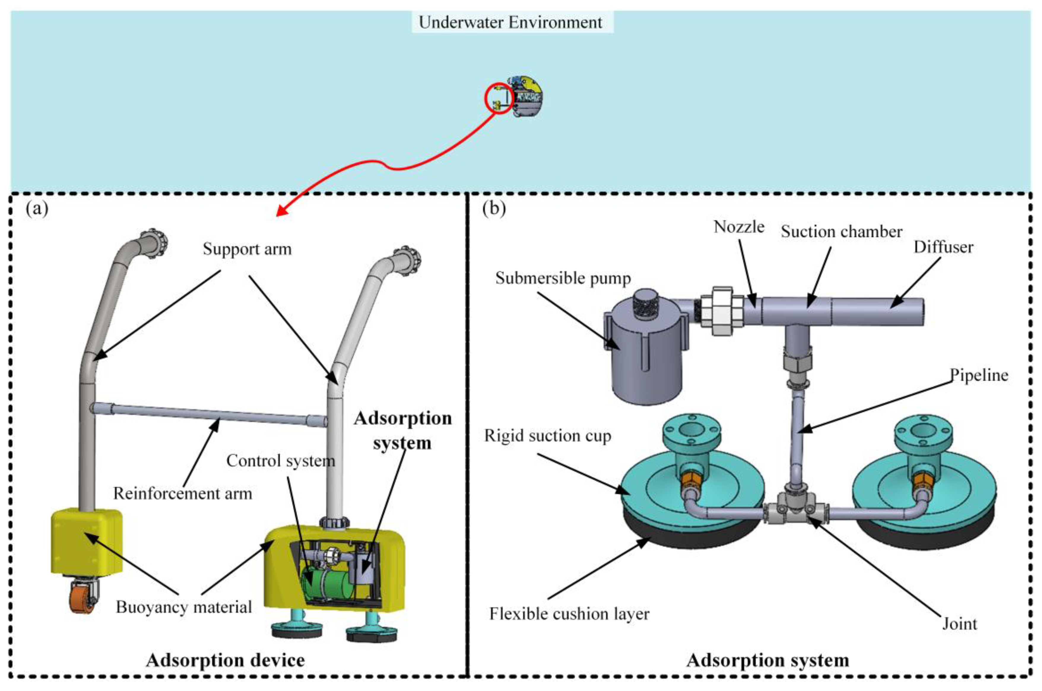
Figure 2.
Working principle of Venturi-based negative pressure generation in underwater adhesion.
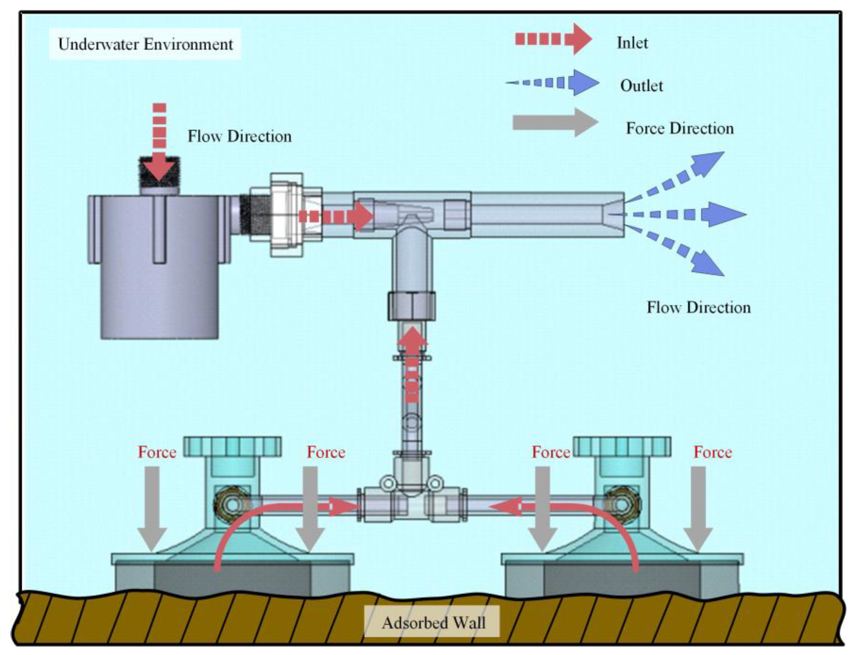
Figure 3.
Theoretical model for adsorption force prediction based on Venturi ejector geometry.
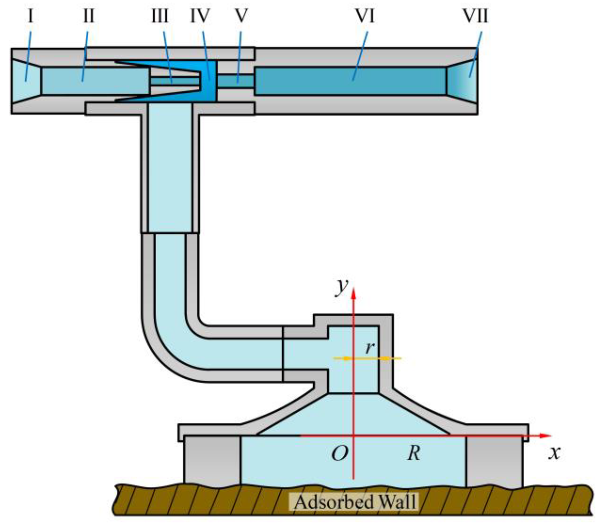
Figure 4.
(a) 3D computational domain for CFD simulation; (b) Grid-independence verification results.
Figure 4.
(a) 3D computational domain for CFD simulation; (b) Grid-independence verification results.
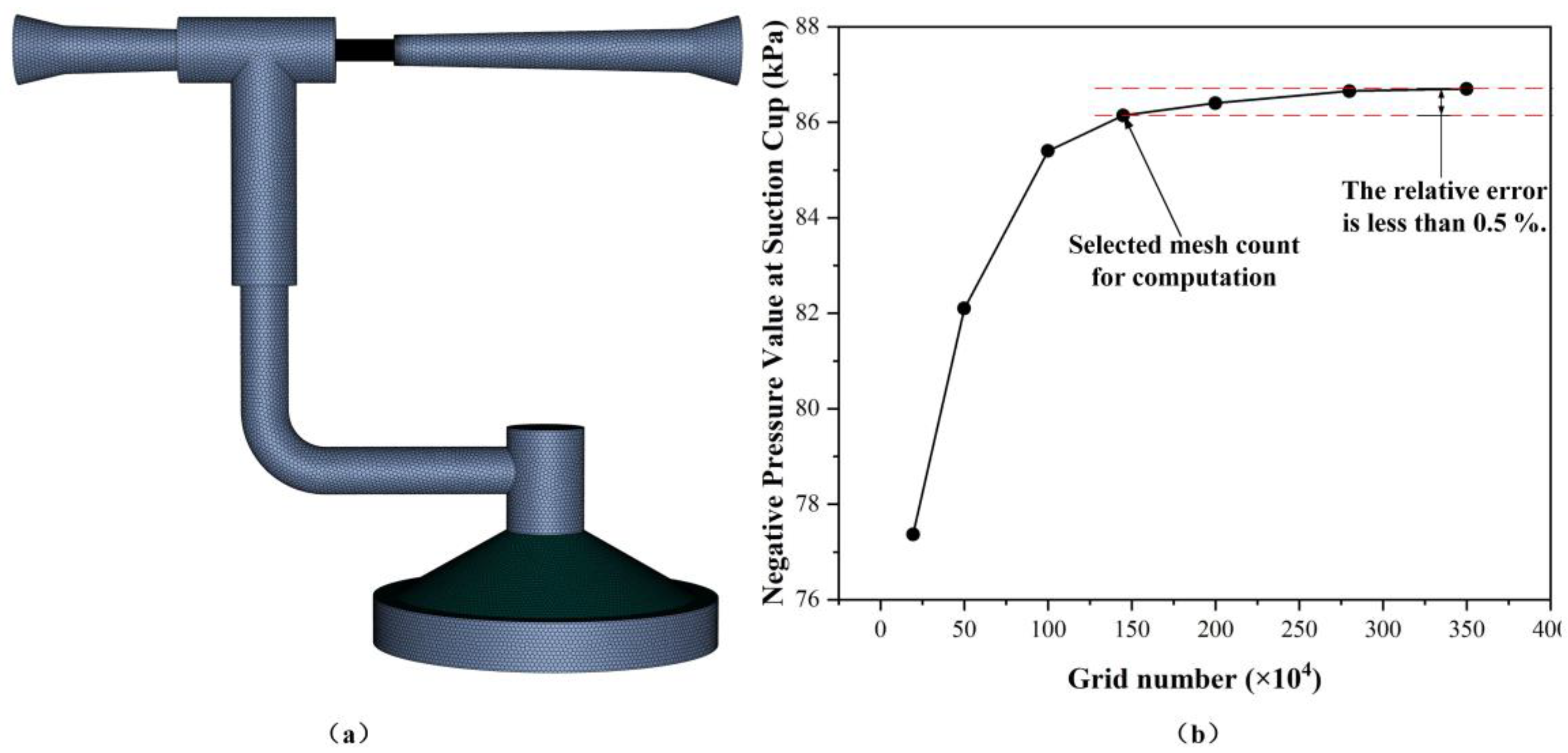
Figure 5.
Adsorption force vs. suction cup inner diameter (d=50–100 mm) under fixed nozzle/throat diameters.
Figure 5.
Adsorption force vs. suction cup inner diameter (d=50–100 mm) under fixed nozzle/throat diameters.
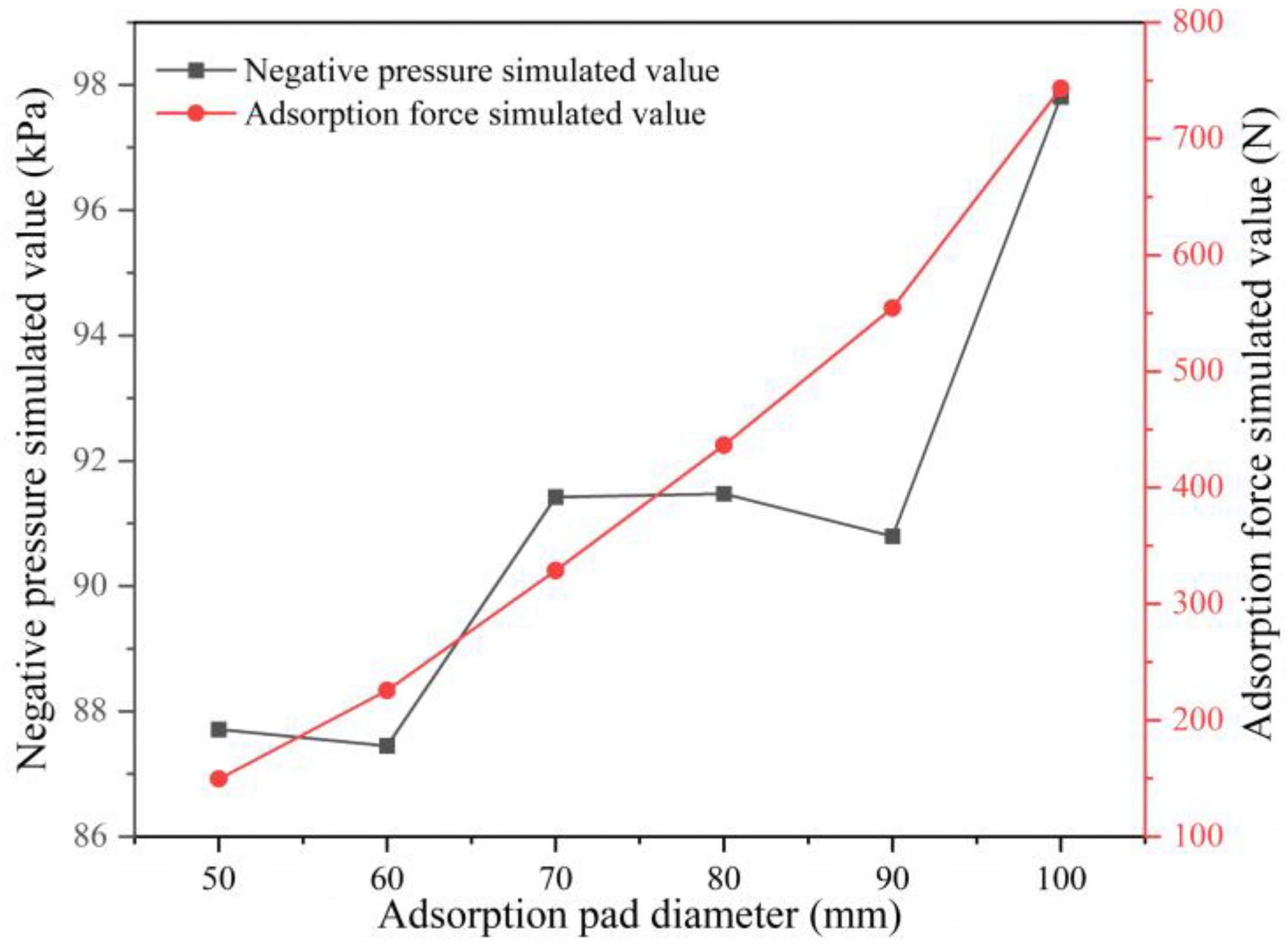
Figure 6.
Pressure contours and axial pressure curves at varying nozzle diameters (a=3.0–4.6 mm).
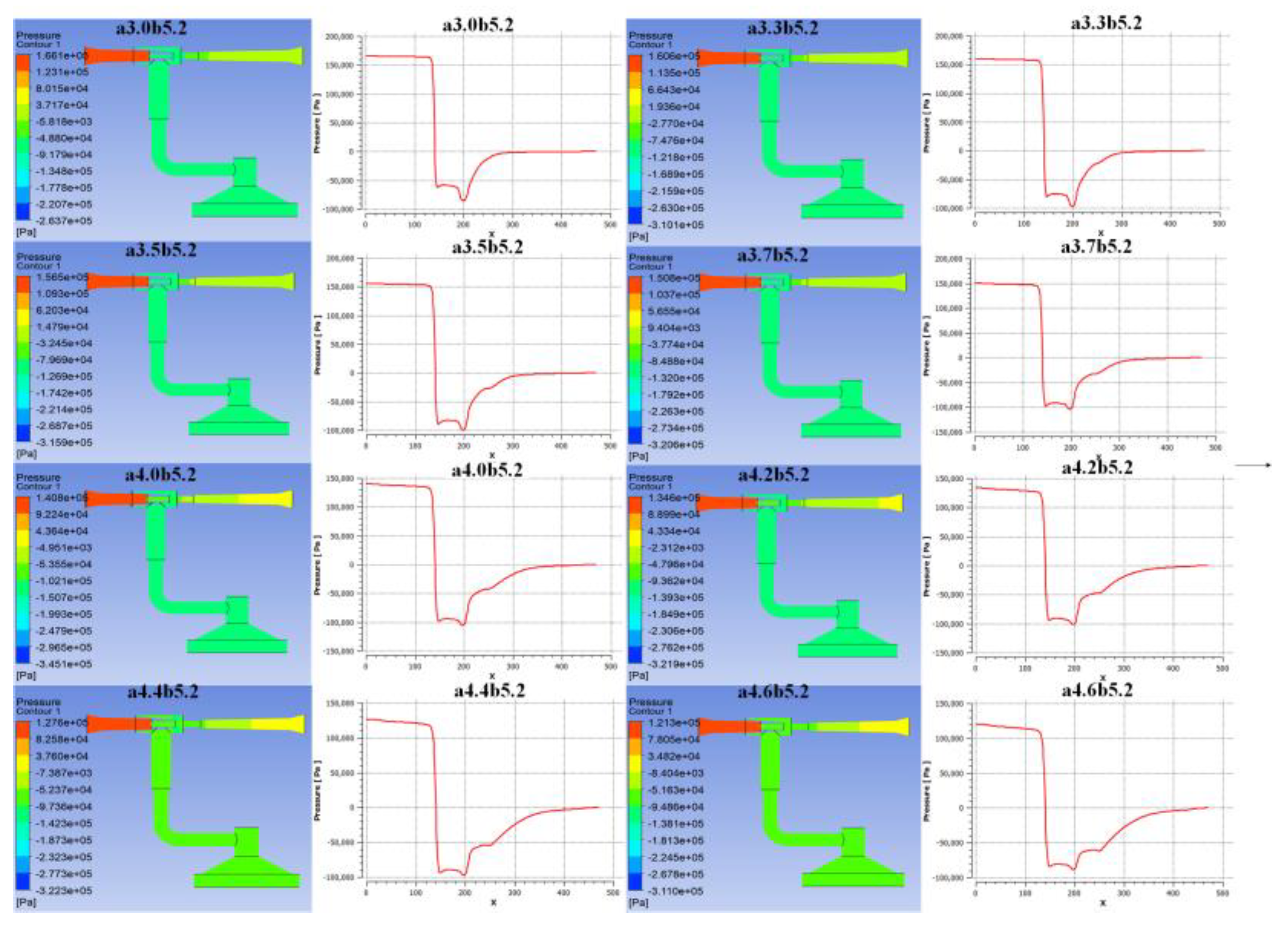
Figure 7.
Velocity contours and axial velocity curves at varying nozzle diameters (a=3.0–4.6 mm).
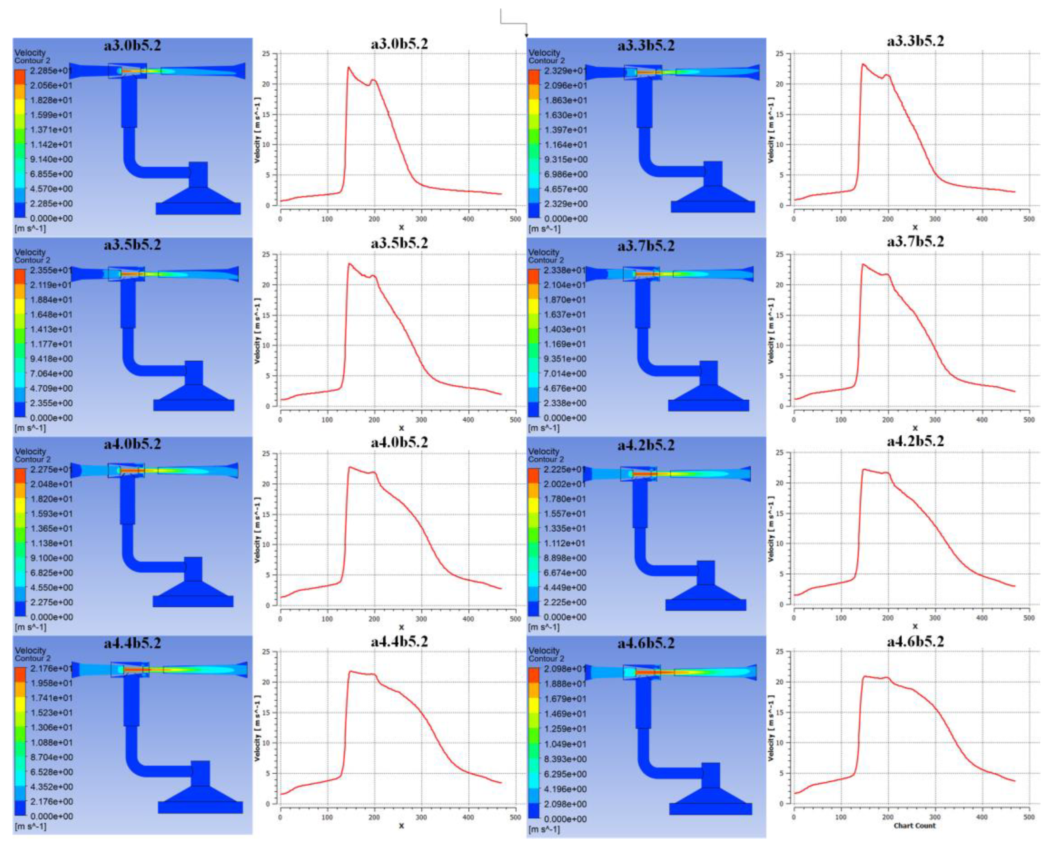
Figure 8.
Correlation between nozzle diameter and negative pressure/adsorption force.
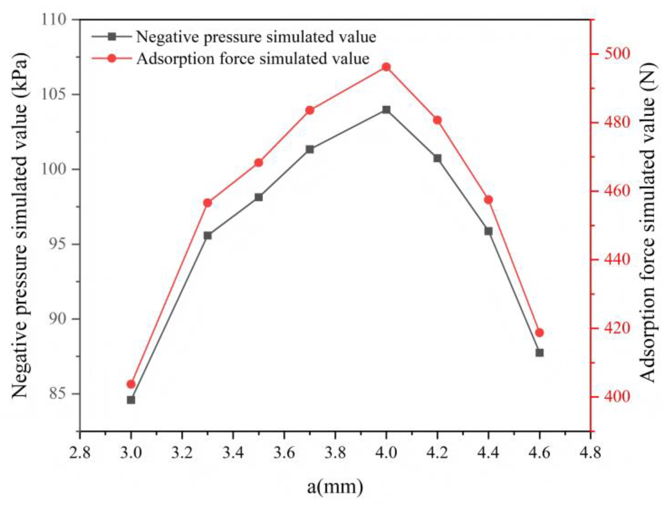
Figure 9.
Pressure contours and axial pressure curves at varying throat diameters (b=4.8–6.2 mm).
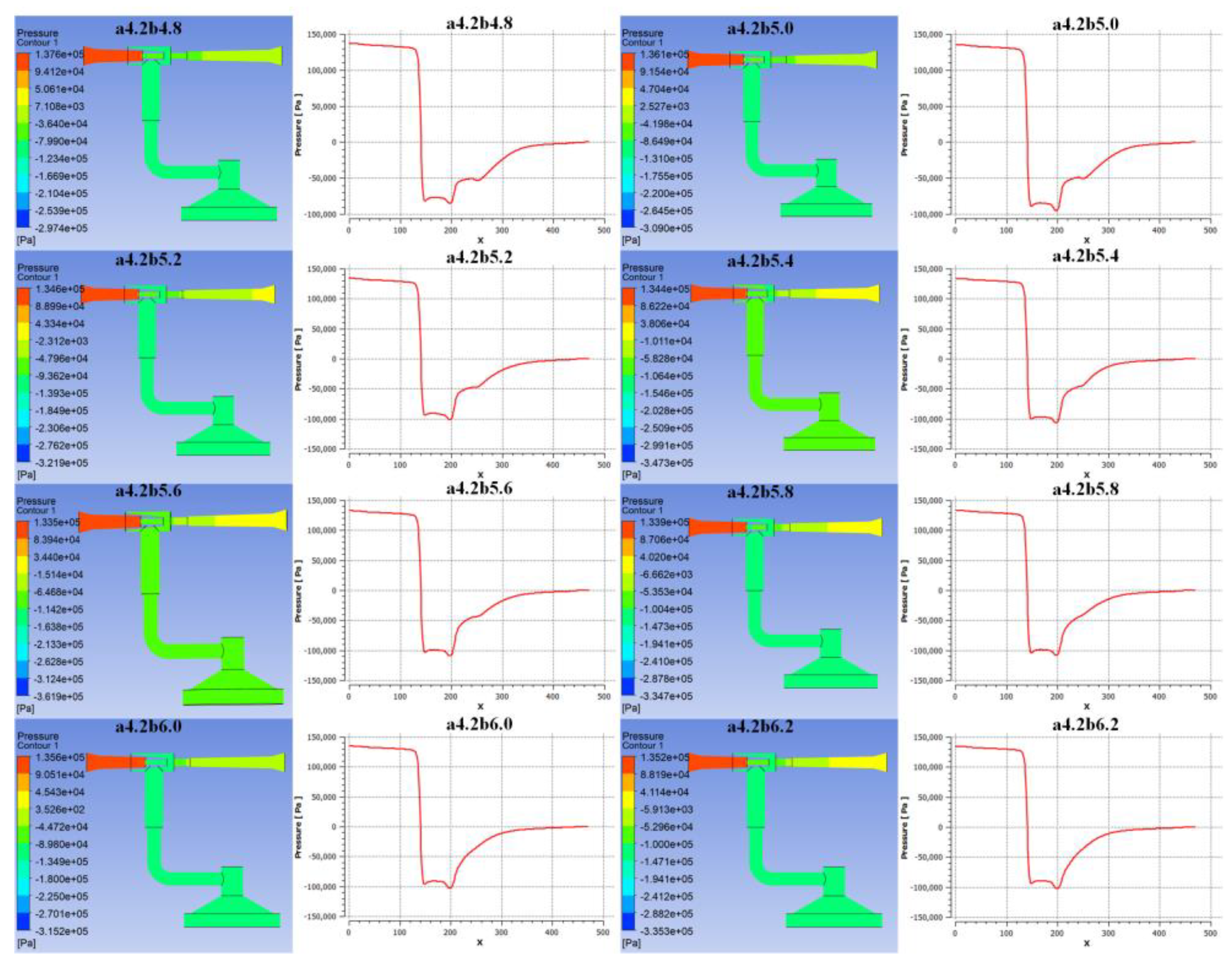
Figure 10.
Velocity contours and axial velocity curves at varying throat diameters (b=4.8–6.2 mm).
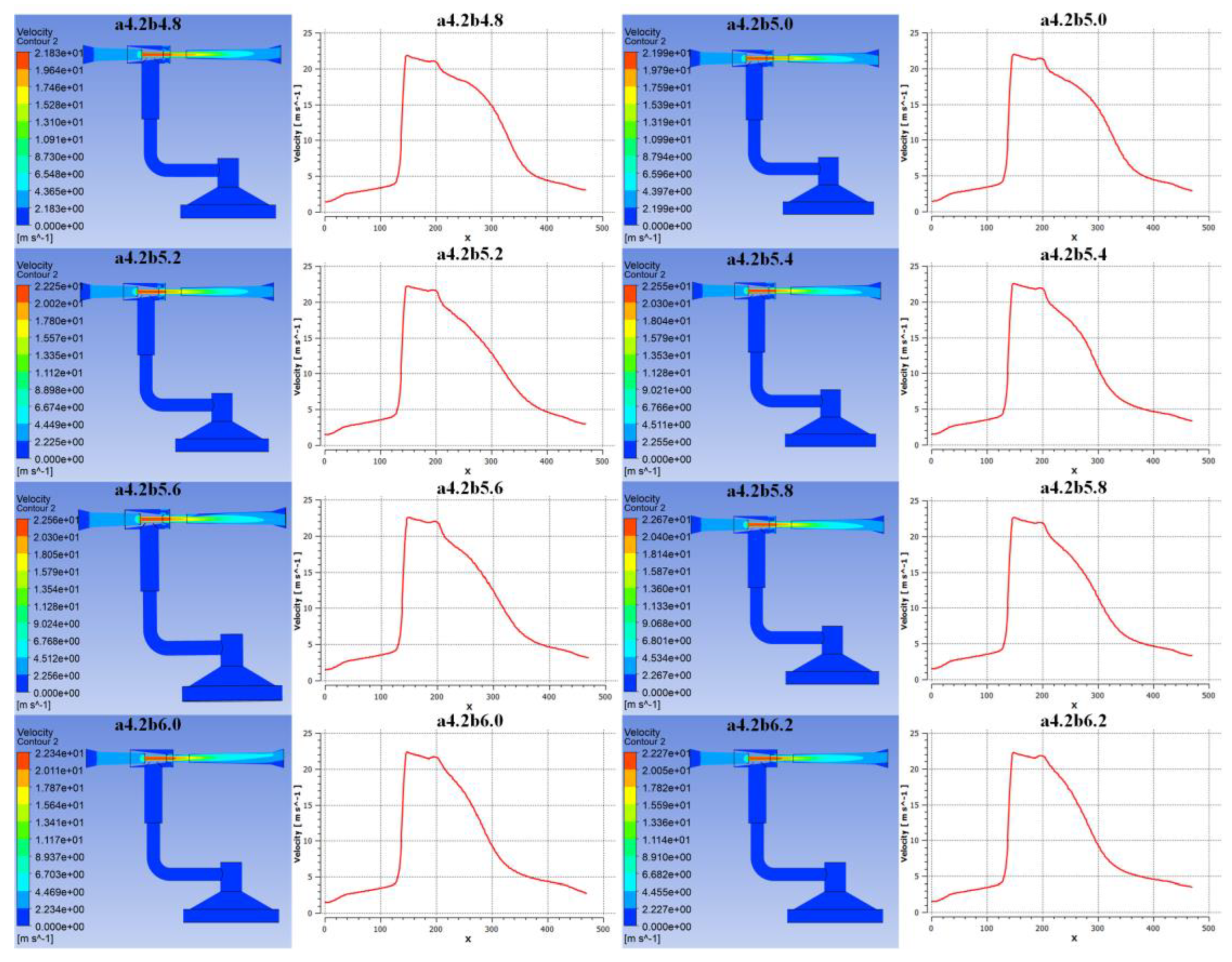
Figure 11.
Correlation between throat diameter and negative pressure/adsorption force.
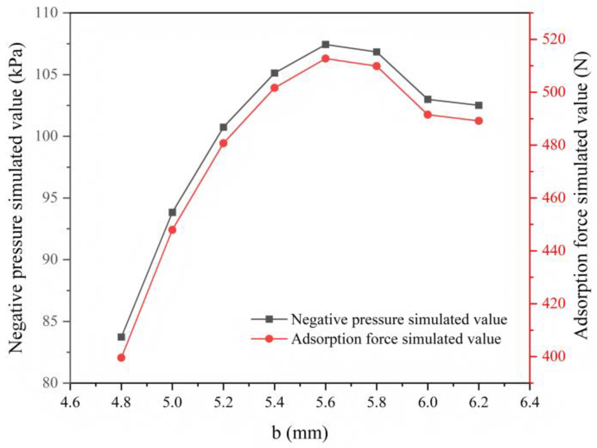
Figure 12.
Synergistic effects of nozzle-throat diameter combinations on (a) negative pressure and (b) adsorption force.
Figure 12.
Synergistic effects of nozzle-throat diameter combinations on (a) negative pressure and (b) adsorption force.
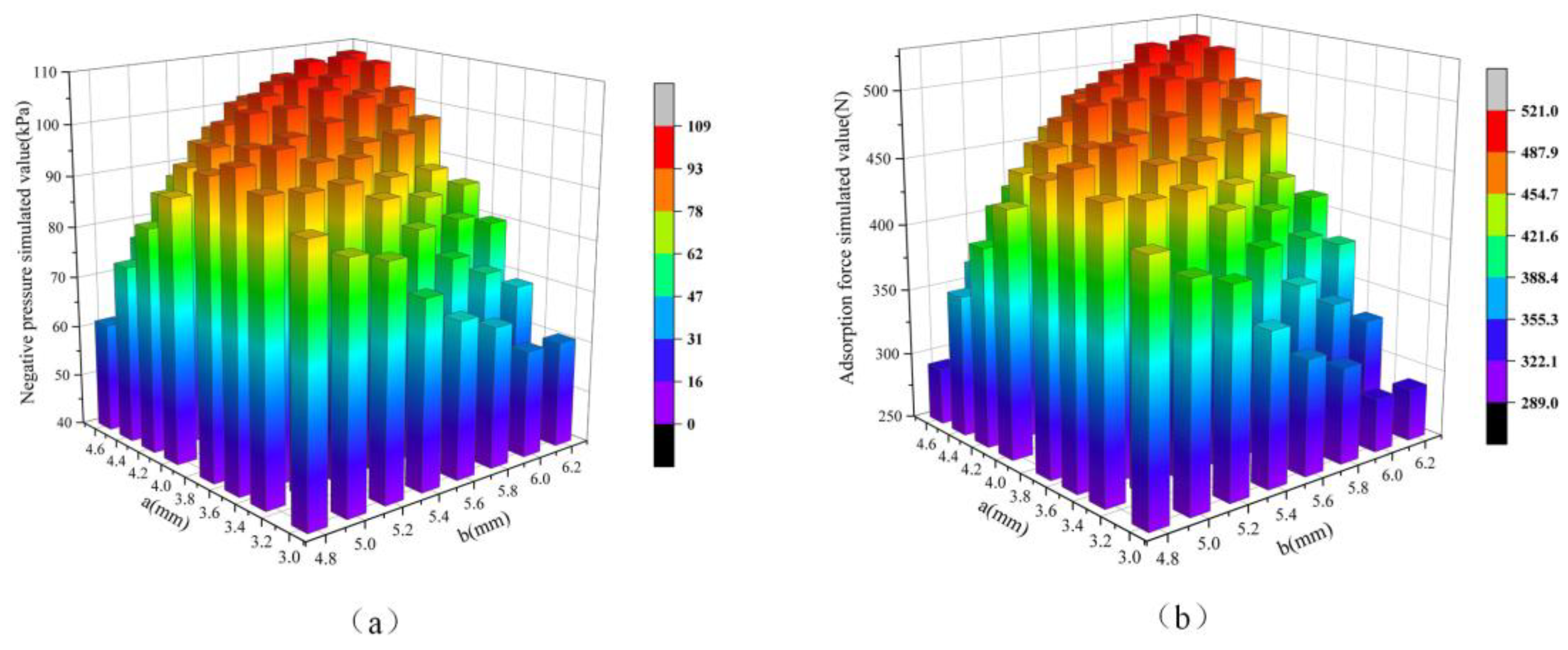
Figure 13.
Experimental setup: (a) Six surface specimens for adaptability testing; (b) Integrated test platform; (c) Fabricated ejector prototypes (H1–H5); (d) EPDM sealing layers; (e) Power consumption profiles.
Figure 13.
Experimental setup: (a) Six surface specimens for adaptability testing; (b) Integrated test platform; (c) Fabricated ejector prototypes (H1–H5); (d) EPDM sealing layers; (e) Power consumption profiles.
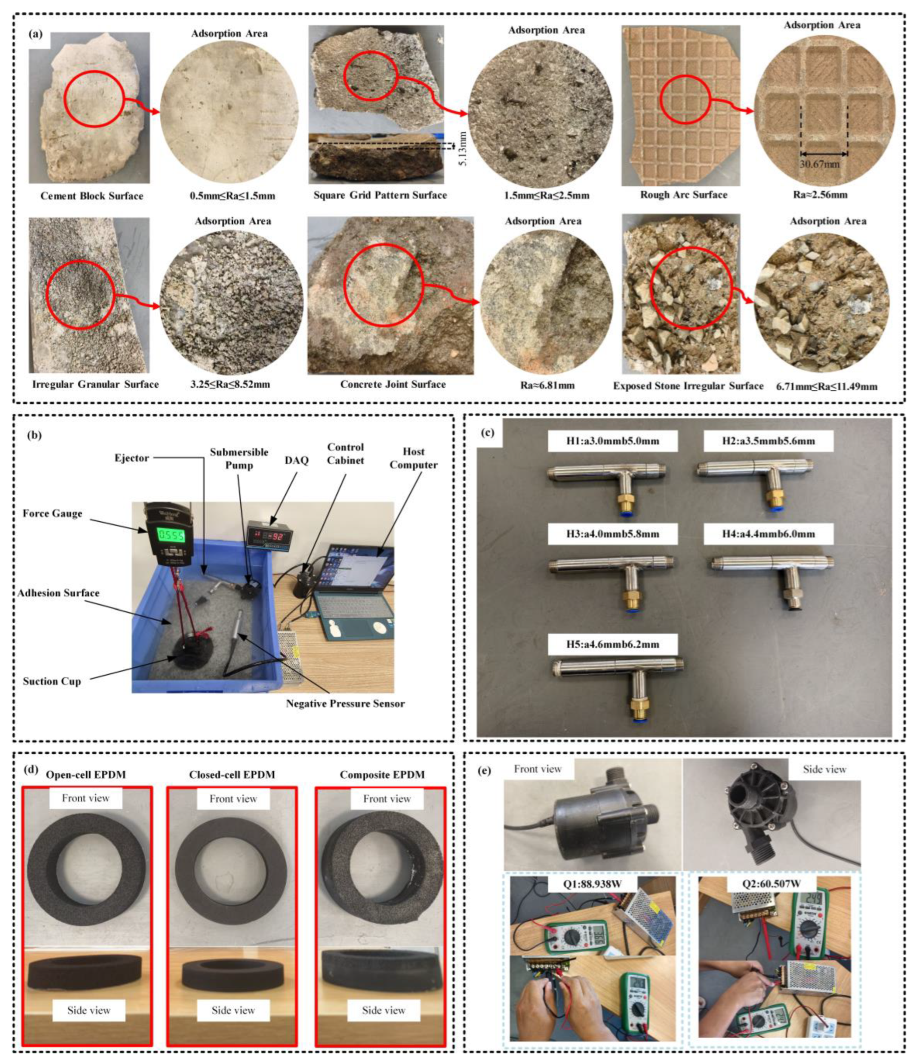
Figure 14.
CFD validation: Comparison between simulated and experimental adsorption forces for prototypes H1–H5.
Figure 14.
CFD validation: Comparison between simulated and experimental adsorption forces for prototypes H1–H5.
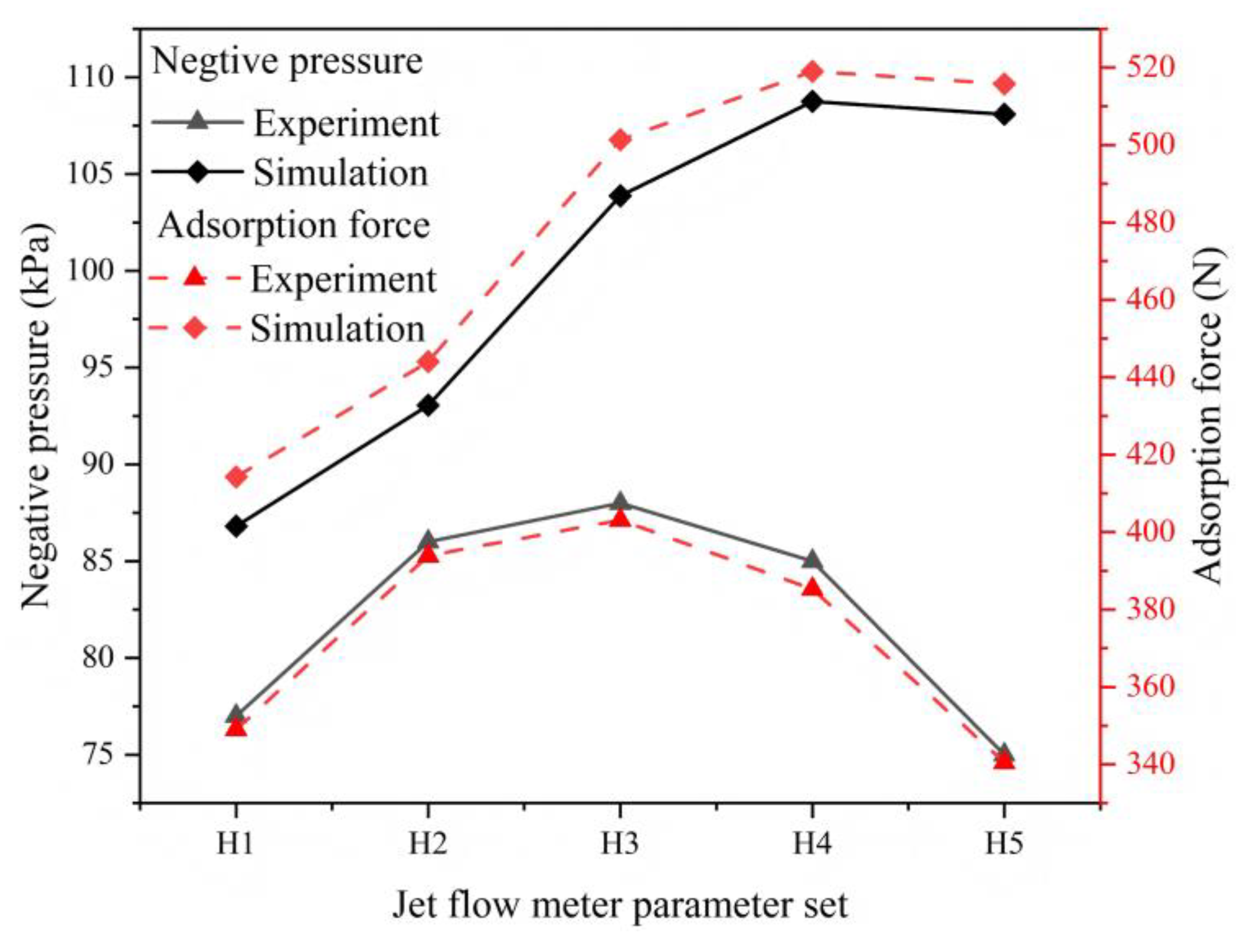
Figure 15.
Impact of power levels on adsorption force across ejector conFigureurations H1–H5.
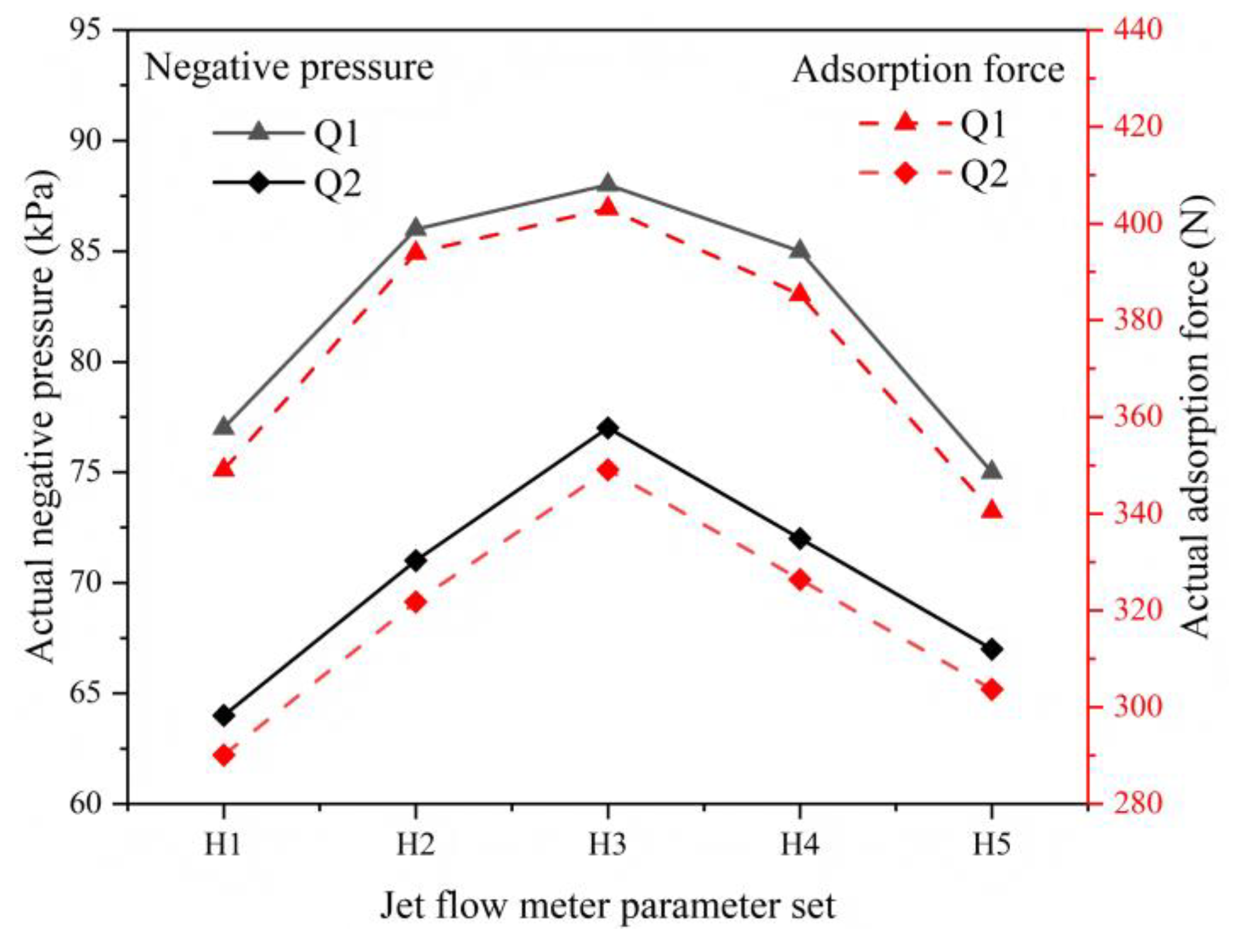
Figure 16.
Surface adaptability: Negative pressure retention across six surface types for three EPDM seal variants.
Figure 16.
Surface adaptability: Negative pressure retention across six surface types for three EPDM seal variants.
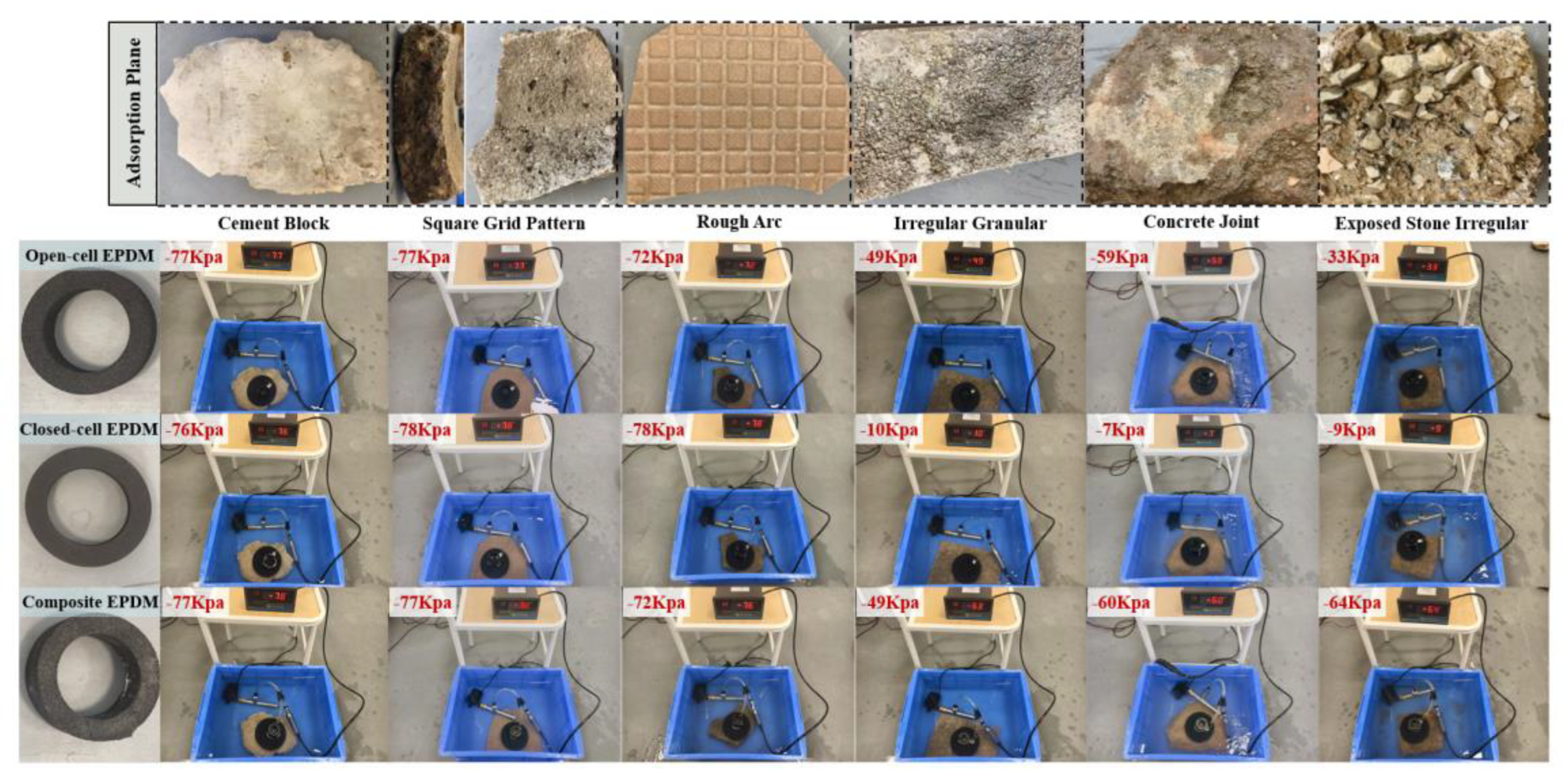
Figure 17.
Robotic integration: (a) Fabricated adsorption unit; (b) Pool test on vertical wall.
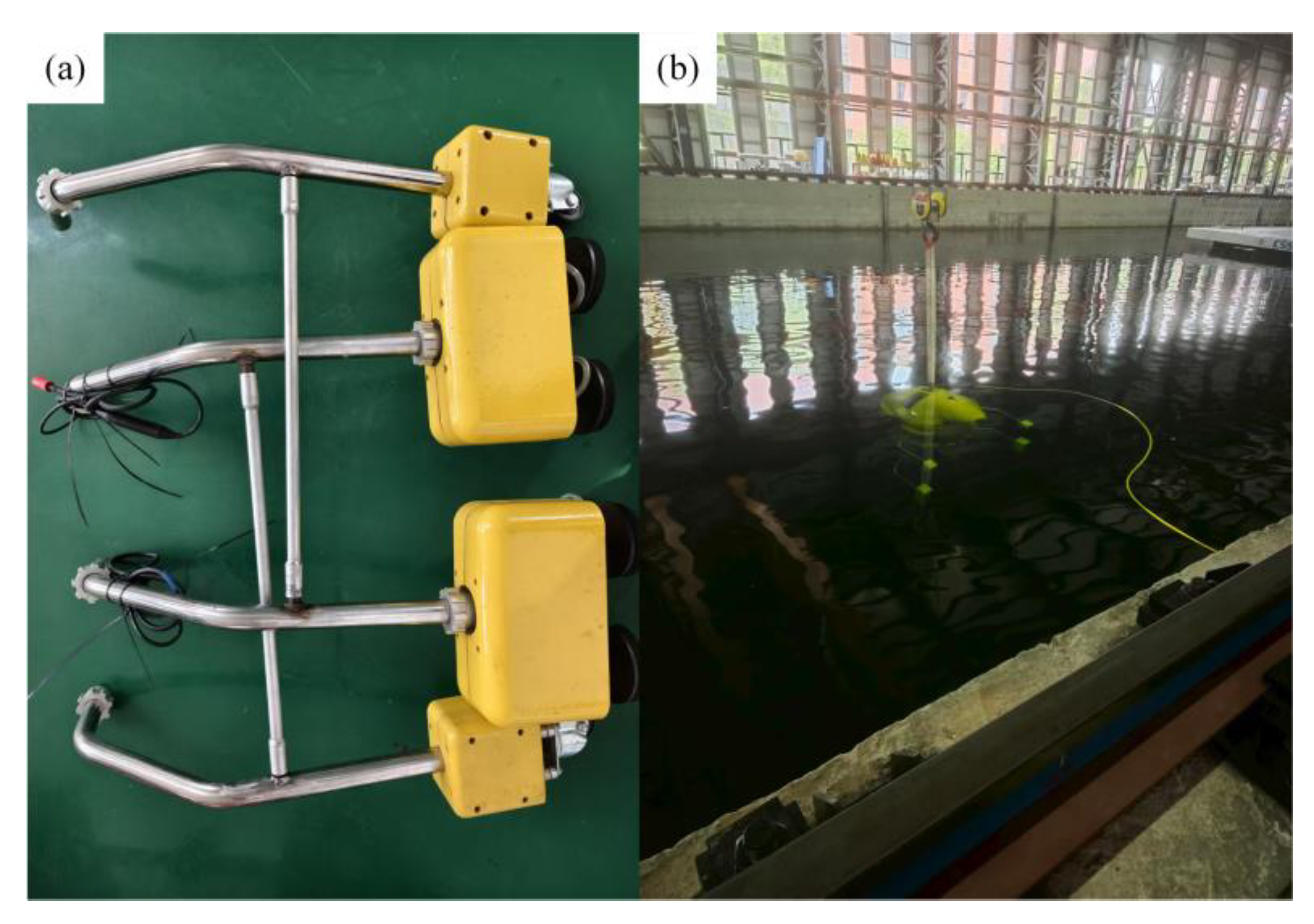
Figure 18.
Field test at Baihetan Dam: (a) Site conditions; (b, c) Robot adhesion stability on dam surface.
Figure 18.
Field test at Baihetan Dam: (a) Site conditions; (b, c) Robot adhesion stability on dam surface.
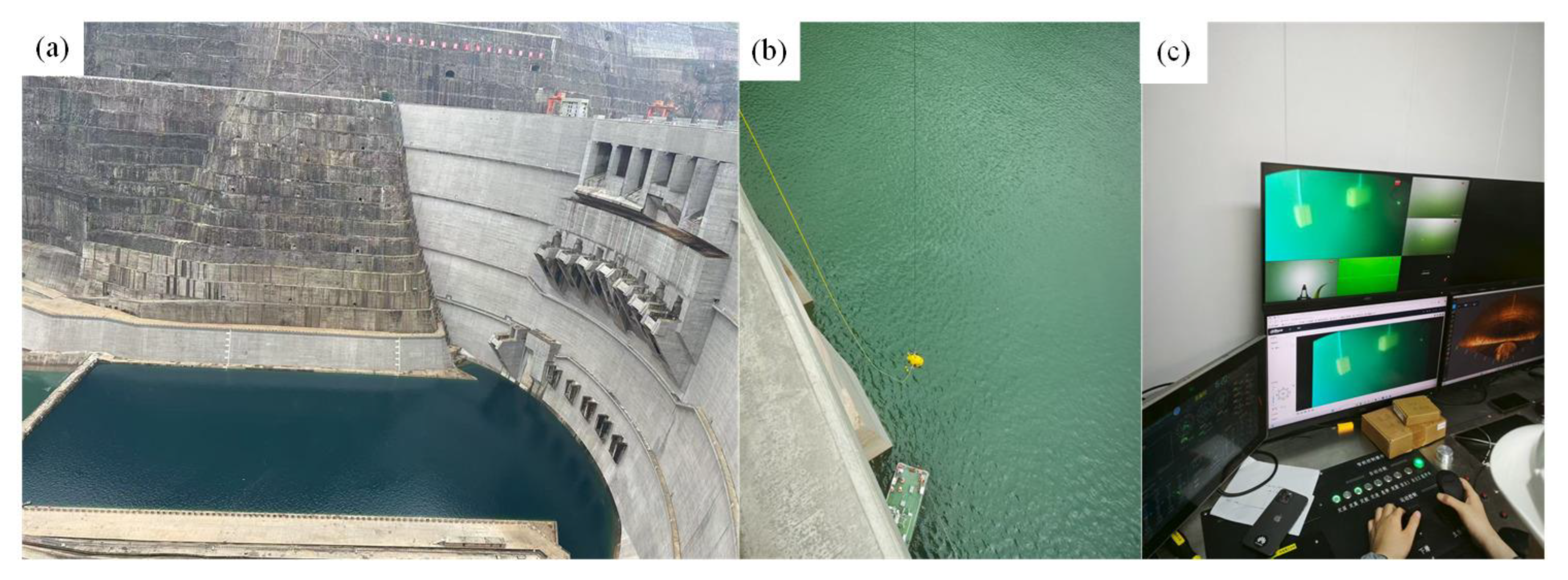

Table 1.
Parameter Selection for Simulation Model.
| Parameter Category | Parameter Name/Symbol | Values Tested | Unit |
| Pump Characteristic | Head-Flow Curve | H=18-2.909v2 | |
| Ejector Geometry | Nozzle Diameter (a) | 3.0、3.3、3.5、3.7、4.0、4.2、4.4、4.6 | mm |
| Throat Diameter (b) | 4.8、5.0、5.2、5.4、5.6、5.8、6.0、6.2 | mm | |
| Suction Cup Geometry | Inner Diameter (d) | 50、60、70、80、90、100 | mm |
Disclaimer/Publisher’s Note: The statements, opinions and data contained in all publications are solely those of the individual author(s) and contributor(s) and not of MDPI and/or the editor(s). MDPI and/or the editor(s) disclaim responsibility for any injury to people or property resulting from any ideas, methods, instructions or products referred to in the content. |
© 2025 by the authors. Licensee MDPI, Basel, Switzerland. This article is an open access article distributed under the terms and conditions of the Creative Commons Attribution (CC BY) license (http://creativecommons.org/licenses/by/4.0/).
Copyright: This open access article is published under a Creative Commons CC BY 4.0 license, which permit the free download, distribution, and reuse, provided that the author and preprint are cited in any reuse.


