
Submitted:
25 August 2025
Posted:
27 August 2025
You are already at the latest version
Abstract
Inspired by the concept of antennas in electromagnetics, this study proposes a novel acoustic metamaterial using Archimedean spiral structures. Unlike traditional resonant absorption structures, present structure does not rely on resonant cavities but consist of multiple channels bent according to specific geometric parameters. The absorption mechanism is attributed to the combination of Fabry-Pérot (FP) resonance and viscous loss effects at waveguide boundaries. A theoretical model based on the transfer matrix method has been established and validated through numerical methods. Furthermore, present study investigated the relationship between absorption performance and geometric parameters through theoretical analysis and numerical simulations, achieving efficient absorption across a wide frequency range and at low frequencies by adjusting these parameters. Additionally, samples have been fabricated using additive manufacturing techniques, and experimental validation confirmed the accuracy of the theoretical and numerical simulations. The structure designed in this paper is expected to be applied to the engineering field with the need of broadband sound absorption.
Keywords:
metamaterial
; Archimedean spiral
; sound absorption
; transfer matrix method
; experiment validation
1. Introduction
As urbanization accelerates, urban industrial noise, traffic noise, and noise from everyday elements such as elevators, transformers, and central air conditioning systems are increasing significantly [1,2]. There is an urgent need to develop and apply compact low-frequency, broad-band materials or structures to meet the growing demand for noise reduction. Traditional noise reduction methods, such as porous materials [3], perforated structures [4], acoustic blankets with mass-loaded layers [5], and gradient refractive index materials [6], have been widely used to mitigate noise pollution. Although these methods are effective in managing noise in the mid to high frequency range, their application is limited due to the requirement for substantial thickness.
The theoretical framework of acoustic metamaterials (and their two-dimensional counterparts, acoustic metasurfaces) originated from electromagnetic analogs, enabling unprecedented control over sound wave propagation through tailored reflection and transmission modulation [7]. These engineered structures further demonstrate potential for acoustic cloaking [8] by redirecting incident waves around objects. In noise control applications, metamaterials have garnered significant attention due to their capacity to achieve near-perfect low-frequency sound absorption [9,10,11,12,13,14,15] at subwavelength thicknesses—a feat unattainable with conventional materials [16,17,18,19,20]. Among prevalent designs, spatially coiled metamaterials stand out for their compact geometries and exceptional low-frequency absorption performance, leveraging coiled air channels to extend acoustic paths within limited volumes. This absorption arises from synergistic mechanisms including: Localized resonance in subwavelength unit cells; Emergence of negative effective mass density or bulk modulus; Critical coupling for impedance matching; Fabry-Pérot resonances within coiled cavities [21,22,23,24]. Despite their subwavelength advantages, the reliance on resonant phenomena introduces inherent trade-offs: strong frequency dispersion and narrow operational bandwidth, which remain fundamental challenges for practical implementations.
To address these limitations, a common approach employs arrays of resonators operating at varied frequencies, broadening the bandwidth via combined local and non-local resonant effects. The introduction of porous matrices into resonant architectures significantly enhances absorption bandwidth, whereas inverse designs improve low-frequency dissipation in porous systems by efficiently entrapping and attenuating sound energy [25,26]. Integrating complementary resonance mechanisms—such as microperforated panels, Helmholtz resonators, and Fabry-Pérot cavities within unified metastructures—enables subwavelength-scale broadband absorption. Theoretical frameworks modeling effective medium properties have further advanced broadband elastic wave absorption [27]. Recent progress extends the Rozanov thickness-bandwidth tradeoff principle (originally from electromagnetics) to acoustic metamaterials, permitting optimization of multi-resonator configurations for targeted sound-absorbing performance.
While contemporary acoustic metamaterial research predominantly targets narrowband quasi-perfect absorption at specific low frequencies or employs multi-resonator arrays for bandwidth expansion, a critical challenge persists: designing a monolithic resonator capable of matching/exceeding the broadband performance of multi-unit systems within subwavelength dimensions. Drawing parallels to spiral antennas in electromagnetic theory, this work pioneers an acoustic metamaterial leveraging Archimedean spiral coiled cavities (ASCC) for broadband low-frequency dissipation. We establish a predictive absorption model via the transfer matrix method, validated against finite element simulations. Theoretical and numerical analyses elucidate the underlying dissipation mechanisms and parametric dependencies, demonstrating that strategic geometric tuning of the ASCC unit enables high-efficiency absorption across an extended low-frequency spectrum without requiring cascaded resonators.
2. Theoretical Model
In general, the sound absorption coefficient of an acoustic absorption structure with a rigid backing can be determined by calculating its surface acoustic impedance as shown in Figure 1.
Below, the surface impedance of the structure is computed using the transfer matrix method. Define the two Archimedean spiral curves that compose the helical waveguide as follows:
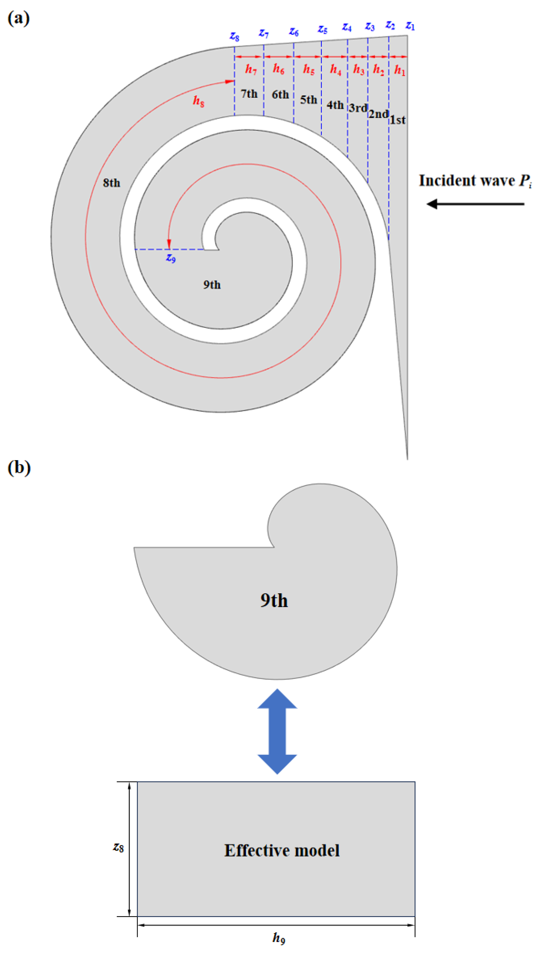
The internal air domain of the structure can be divided into three main sections: The first section is the region with a gradual change in channel dimensions. To reduce computational effort while maintaining accuracy, this section is divided into 7 smaller parts, labeled 1st to 7th in the Figure 2, with cross-sectional dimensions of si and cross-sectional impedance of zi. The second section is the helical part of the channel with a constant dimension of s8. The third section is the irregular portion at the end of the channel. The transfer matrix for the internal section of the i-th is given by:
Where u represents the volumetric velocity, and ρ0 = 1.21 kg/m3 and c0 = 343m/s denote the density and speed of sound in air, respectively. The normal acoustic impedance of the i-th section can be expressed as:
For the helical section of the channel cross-section, it can be equivalently represented as a rectangular channel with dimensions z8 and h8, where h8 is the length of the rectangular channel, it can be expressed:
For the irregular region at the end, it can be simplistically represented as a rectangle with the same area. The dimensions of the rectangle are z8 and h9. The area of the irregular region A9 and the equivalent channel length h9 can be expressed as:
The end of the waveguide is a rigid boundary, and its impedance is considered to be infinite. Therefore, z9 can be represented as
Therefore, the reflection coefficient R and the absorption coefficient α of the structure can be computed as follows:
Figure 3.
(a)Schematic of the transfer matrix (TM) method; (b) effective medium model of the the third section.
Figure 3.
(a)Schematic of the transfer matrix (TM) method; (b) effective medium model of the the third section.
3. Finite Element Model
The Finite Element Method (FEM) is an effective numerical technique for acoustic prediction of complex geometric structures. In this study, COMSOL Multiphysics finite element software is utilized for simulation. A model is established in the pressure acoustic domain, as shown in Figure 4, to solve the linearized continuity equation, Navier-Stokes equations, and energy equations. Given that the stiffness of the structure is significantly greater than that of the air, only the medium within the structure is considered in the model, with a hard acoustic boundary condition applied at the external boundary, indicating zero acceleration and velocity at the interface. The air domain above the structure serves as the background acoustic field, providing an incident sound pressure of 1 Pa. A Perfectly Matched Layer (PML) is applied above the background acoustic field to completely absorb scattered sound waves, ensuring that reflections at the boundary between the PML and the acoustic field do not affect the accuracy of the calculation. The structure domain uses a free triangular mesh, while the mesh for the air domain and PML is obtained by boundary layer sweeping, with the mesh size being less than 1/6 of the longest wavelength. The computational frequency range is constrained by the plane wave assumption, and the cutoff frequency is given by Equation:
Here, c0 is the speed of sound in air, and R is the geometric dimension of the structure’s cross-section. Respectively the impedance Zs at the sound wave incidence interface and the absorption coefficient α can be obtained from Equations (9):
The complex sound speed c=c0(1+0.05j) is used to account for the effects of damping, where 0.05 represents the damping loss factor, which approximately simulates the thermal viscous losses of the structure.
4. Results and Discussion
4.1. Sound Absorption Performance of the ASCC
Figure 5 shows the sound absorption coefficients of the structure calculated using both FEM and TMM. It is evident that the results from both methods are in good agreement, validating the accuracy of the theoretical model. However, discrepancies between the two methods are observed in the high-frequency range of 4000 Hz to 6000 Hz. This is attributed to the complex propagation modes of high-frequency sound waves within the waveguide, which are not simply plane waves. The transfer matrix method assumes plane wave propagation in the waveguide, leading to discrepancies. The quarter-wavelength resonance generated by AS results in high sound absorption at the peak values. Figure 6a presents the sound pressure maps at the three peak frequencies, corresponding to three different resonance modes. The AS waveguide length can be determined from the formula, and for the resonance frequencies of 1022 Hz, 3069 Hz, and 5021 Hz, the waveguide length is an odd integer multiple of their quarter-wavelengths, satisfying the equation L=nλi/4. Figure 6b displays the total power density of the plane waves, reflecting the sound energy dissipation. It can be observed that at the peak absorption frequencies, sound energy dissipation is mainly concentrated on the inner wall near the waveguide’s pole. For 1022 Hz, the energy dissipation is relatively uniform, while at 3069 Hz and 5021 Hz, energy dissipation is primarily concentrated at the front section of the waveguide, focusing at the end where the waveguide’s size gradient transitions.
4.2. Influence of Radial Growth Rate b
The radial growth rate characterizes how the spiral radius changes with angle. This section investigates the effects of three different radial growth rates on the sound absorption performance of the structure. To ensure a certain spatial efficiency, the spiral rotation angle is smaller when the radial growth rate is high compared to when it is low. It can be inferred that a slower radial growth rate results in a longer waveguide with a smaller cross-sectional area, while a faster growth rate leads to a shorter waveguide with a larger cross-sectional area. The theoretical model based on the transfer matrix method and the finite element model were used to calculate the sound absorption coefficients of the structure, with results shown in Figure 2. Both methods agree well across the frequency range, with minor discrepancies at high frequencies, consistent with previously explained patterns. For b=1.8, the structure exhibits a lower absorption peak at 2234 Hz; for b=0.9, there are three absorption peaks at 1022 Hz, 3069 Hz, and 5021 Hz, with the highest peak at 3069 Hz reaching 0.98; for b=0.6, four absorption peaks are observed at 677 Hz, 2013 Hz, 3353 Hz, and 4667 Hz, with the highest peak at 677 Hz reaching 0.998. The number of absorption peaks varies due to different waveguide lengths; longer waveguides produce more absorption peaks.
Figure 7.
(a) The cross section (b) sound absorption coefficients. (c) reflection coefficient in the complex frequency plane with different values of b.
Figure 7.
(a) The cross section (b) sound absorption coefficients. (c) reflection coefficient in the complex frequency plane with different values of b.
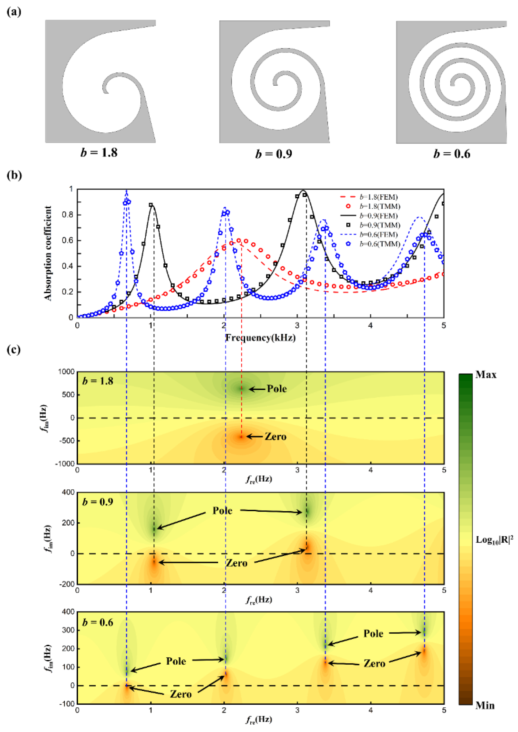
To further study the mechanism by which the radial growth rate affects absorption, a graphical method was employed to examine the reflection coefficients in the complex frequency plane. By introducing an imaginary frequency fi, where f=fr+ifi (with fr as the real frequency), and substituting the complex frequency into the reflection coefficient formula, the complex frequency reflection coefficient plots were obtained, as shown in Figure 3. Green and red points denote the extremal values of the complex reflection coefficients, called zeros and poles, respectively. In a lossless acoustic system, zeros and poles are symmetrically distributed around the real axis (black dashed line). When structural losses are considered, zeros and poles shift along the positive imaginary frequency axis. For b=1.8, the zeros and poles shift slightly, resulting in a single low absorption peak due to the system being in an underdamped state. For b=0.9, the structure is underdamped at 1022 Hz and overdamped at 3069 Hz. The zeros are closer to the real axis at these frequencies, leading to higher absorption peaks, with the peak at 3069 Hz being higher due to the zero being closer to the origin compared to 1022 Hz. For b=0.6, the zero at 677 Hz falls on the real axis, achieving perfect absorption with a peak value of 0.998. As the frequency increases, the system becomes increasingly overdamped, resulting in lower absorption peaks at the higher frequencies.
4.3. Influence of Initial Angle θ0
For a given Archimedean spiral curve, the starting angle affects the length of the spiral structure. As illustrated in Figure 8a, the 2D schematic diagrams for starting angles of 0°, 90°, 180°, and 270° are shown. The length of the bent waveguide decreases with an increase in the starting angle, while the volume of the end cavity gradually increases. Figure 8b presents the sound absorption coefficient maps for different starting angles in the frequency range of 0-6000 Hz. As the starting angle increases, the second peak of sound absorption shifts to higher frequencies. The second absorption peak for starting angles of 0° and 90° is relatively close, whereas for 180° and 270°, there is a notable deviation. This deviation is attributed to the fact that although the gradient of the starting angle change is 90°, a larger angle causes more significant variations in waveguide length, thereby affecting the second absorption peak. A similar effect is observed for the third absorption peak. This section also examines the phase variation of the reflection coefficient on the complex plane and the Argand diagram, as shown in Figure 8c.
At resonant frequencies, the phase of the reflection coefficient exhibits abrupt changes, resulting in high sound absorption. The Argand diagram is commonly used to analyze the structural resonant state and changes in amplitude and phase upon reflection. The Argand diagram of the reflection coefficient appears as a curve rotating around the origin. At 0 Hz, the coordinate is at 1 on the real axis, and as the frequency increases, the curve rotates clockwise. Without considering losses, the Argand diagram is a circle with a radius of 1. When structural losses are considered, the trajectory becomes an elliptical path around the origin, enclosed within a circle of radius 1, shifting along the real axis. As losses increase, the diameter of the circumscribed circle of the ellipse decreases, and the ellipse shifts towards the positive axis. The diameter of the circumscribed circle is inversely proportional to the loss. If the loss exceeds the critical coupling requirement, the trajectory does not include the origin. When the trajectory includes the origin, it indicates insufficient loss. Figure 8d shows the Argand diagram for 0-3000 Hz, revealing that at low frequencies, all four structures exhibit insufficient loss, with absorption peaks of 0.872, 0.869, 0.859, and 0.832, respectively. Figure 8e for 3000-6000 Hz indicates that structures with starting angles of 0°, 90°, and 180° have excessive loss, with absorption peaks of 0.988, 0.992, and 0.999, respectively, while the structure with a starting angle of 270° has insufficient loss, with an absorption peak of 0.997. Notably, for a starting angle of 180°, the curve is very close to the origin at a frequency of 3370 Hz. Although the system impedance does not perfectly match the air impedance, the absorption peak is 0.999 (approximately 1), achieving near-perfect absorption.
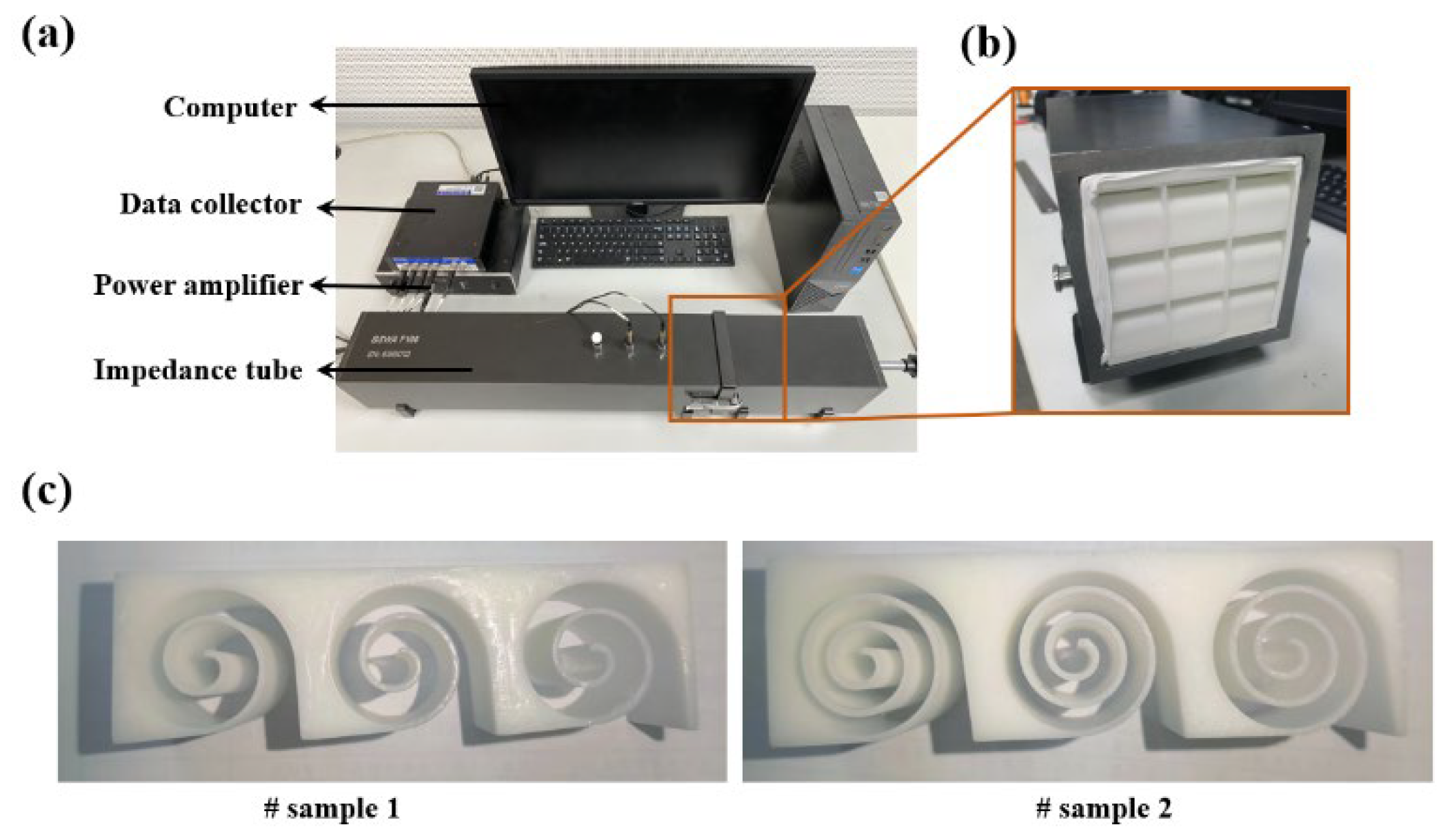
5. Experimental Verification
To further validate the accuracy of the theoretical and simulation calculations, experiments were conducted using the BSWA SW422 impedance tube as shown in Figure 9a. Acoustic absorption tests were performed on two types of Archimedean spiral metamaterials with different parameters using the VA-Lab testing system and the transfer function method, as depicted in the figure. To minimize the variability in experimental results, the average of 12 experimental data sets was taken. The structures were 3D printed using white resin, with overall dimensions of 100 mm × 100 mm × 30 mm. The samples were edge-sealed with raw material tape and then installed within the impedance tube, as shown in Figure 9b.
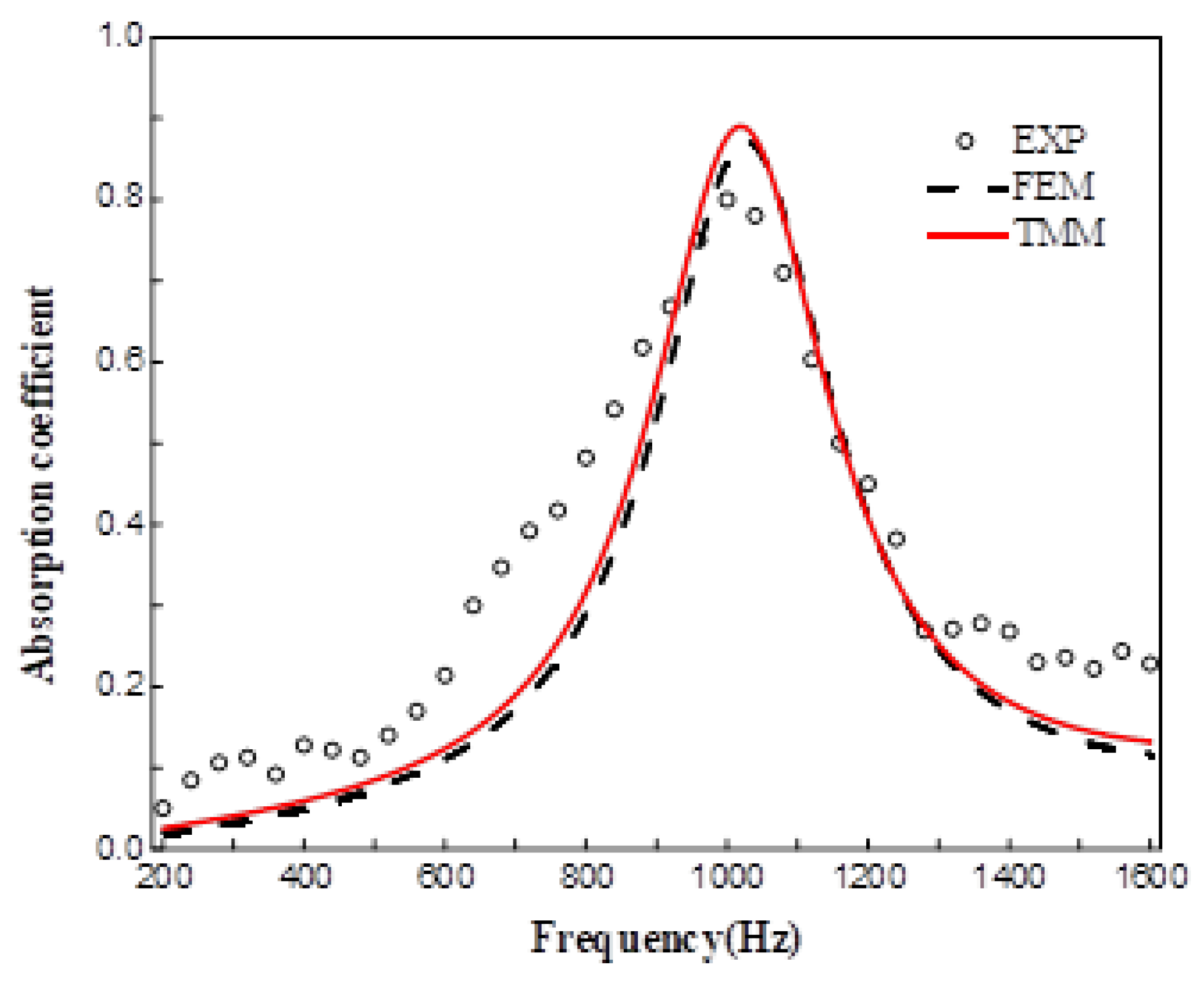
The accuracy of the theoretical model was validated by comparing the acoustic absorption coefficient curves obtained from the ASCC theoretical model, simulation results, and experimental results in the frequency range of 200–1600 Hz, as shown in Figure 8 and Figure 9. It is evident that the absorption curves obtained from the three methods exhibit the same trend, with a similar number of absorption peaks and peak frequencies that are very close, thus confirming the predictive accuracy of the theoretical model. Discrepancies between the results may stem from several factors: firstly, sample fabrication errors, such as structural dimension inaccuracies due to the precision limitations of 3D printing; secondly, experimental testing errors, such as gaps between the sample and the inner wall of the impedance tube, and the difficulty in achieving ideal normal incidence of plane waves during the experimental process.
Figure 10.
Sound absorption coefficients of sample 1.
5. Conclusions
This study investigates acoustic metamaterials incorporating Archimedean spiral structures. Diverging from conventional resonant absorption designs reliant on cavity resonances, the proposed architecture utilizes multi-channel waveguides curved with precisely controlled geometric parameters. Its absorption characteristics arise from Fabry-Pérot (FP) resonances and viscous boundary losses within the waveguide channels.
An acoustic absorption model was developed based on the transfer matrix method and validated through numerical simulations, demonstrating strong consistency between theoretical predictions and computational results. Theoretical analysis and parametric studies revealed that the number and magnitude of absorption peaks are predominantly governed by the spiral waveguide length, where increased length induces higher-order resonant modes and broader peak distribution. Through optimization of geometric parameters, efficient broadband low-frequency absorption was achieved.
Experimental validation was conducted using 3D-printed prototypes, confirming the accuracy of both theoretical and numerical models. Future work will focus on parallel configurations of heterogeneous unit cells to further broaden the effective absorption bandwidth and investigate coupling effects between adjacent units on collective acoustic performance.
Author Contributions
methodology, writing—original draft preparation, S.Y.; software, writing—review and editing, H.M.; validation, formal analysis, Y.L.; Conceptualization, investigation, resources, funding acquisition, supervision, C.S.; All authors have read and agreed to the published version of the manuscript.
Funding
This research was funded by the National Key Research and Development Program of China (No. 2023YFB4604800), Natural Science Foundation of China (Nos. 12202183 and 12472089). Open Fund of Key Laboratory of Materials Preparation and Protection for Harsh Environment (Nanjing University of Aeronautics and Astronautics), Ministry of Industry and Information Technology (56XCA24025), Research Fund of State Key Laboratory of Mechanics and Control for Aerospace Structures (Nanjing University of Aeronautics and astronautics) (Grant No. MCAS-I-0225G05).
Data Availability Statement
The original contributions presented in this study are included in the
article. Further inquiries can be directed to the corresponding author.
Conflicts of Interest
The authors declare no conflicts of interest.
References
- Liu, Z.; Zhang, X.; Mao, Y.; Zhu, Y. Y.; Yang, Z.; Chan, C. T.; Sheng, P. Locally resonant sonic materials. Science 2000, 289(5485), 1734–1736. [Google Scholar] [CrossRef] [PubMed]
- Dolling, G., Enkrich, C., Wegener, M., Soukoulis, C. M., Linden, S. Simultaneous negative phase and group velocity of light in a metamaterial. Science, 2006. 312(5775), 892-894. [CrossRef]
- Mei, J., Ma, G., Yang, M., Yang, Z., Wen, W., Sheng, P. Dark acoustic metamaterials as super absorbers for low-frequency sound. Nat. Commun, 2012. 3(1), 756. [CrossRef]
- Li, Y., Assouar, B. M. Acoustic metasurface-based perfect absorber with deep subwavelength thickness. Appl. Phys. Lett, 2016. 108(6). [CrossRef]
- Jiménez, N., Huang, W., Romero-García, V., Pagneux, V., Groby, J. P. Ultra-thin metamaterial for perfect and quasi-omnidirectional sound absorption. Appl. Phys. Lett, 2016.109(12). [CrossRef]
- Kronowetter, F., Pretsch, L., Chiang, Y. K., Melnikov, A., Sepehrirahnama, S., Oberst, S., Marburg, S. Sound attenuation enhancement of acoustic meta-atoms via coupling. J. Acoust. Soc. Am, 2023. 154(2), 842-851. [CrossRef]
- Gao, N., Zhang, Z., Deng, J., Guo, X., Cheng, B., Hou, H. Acoustic metamaterials for noise reduction: a review. Adv. Mater. Technol, 2022. 7(6), 2100698. [CrossRef]
- Tian, R., Xu, S. M., Xu, Q., Lu, C. Large-scale preparation for efficient polymer-based room-temperature phosphorescence via click chemistry. Sci. Adv, 2020. 6(21), eaaz6107. [CrossRef]
- Shao, C., Long, H., Cheng, Y., Liu, X. Low-frequency perfect sound absorption achieved by a modulus-near-zero metamaterial. Sci. Rep, 2019. 9(1), 13482. [CrossRef]
- Jiang, Y, Li, Z., Ren, J., Feng, X., Gao, J., Shen, C., Meng, H., Lu, T. Autoencoder artificial neural network for accelerated forward and inverse design of locally resonant acoustic metamaterials. J. Appl. Phys. 2025; 137 (5): 053104. [CrossRef]
- Donda, K., Zhu, Y., Fan, S. W., Cao, L., Li, Y., Assouar, B. Extreme low-frequency ultrathin acoustic absorbing metasurface. Appl. Phys. Lett, 2019. 115(17). [CrossRef]
- Gao Z, Ma Q , Yang J, Shen C, Meng H. Origami-based acoustic metamaterial for low-frequency adjustable sound absorption. J. Sound Vib., 2025. 618119334. [CrossRef]
- de Sousa, A. C., Deckers, E., Claeys, C., Desmet, W. On the assembly of Archimedean spiral cavities for sound absorption applications: Design, optimization and experimental validation. Mech. Syst. Signal. Pr, 2021. 147, 107102. [CrossRef]
- Huang, Y.; Fan, Q.; Wang, X.; Liu, Z.; Shi, Y.; Liu, C. Study on Acoustic Metamaterial Unit Cells: Acoustic Absorption Characteristics of Novel Tortuously Perforated Helmholtz Resonator with Consideration of Elongated Acoustic Propagation Paths. Materials, 2025. 18, 3930. [CrossRef]
- Kronowetter, F., Wagner, P., Kolodi, J., Brabandt, I., Neumeyer, T., Rümmler, N., & Marburg, S. Novel compound material and metamaterial wheelhouse liners for tire noise reduction. Mech. Syst. Signal. Pr, 2023. 200, 110548. [CrossRef]
- Krasikova, M., Krasikov, S., Melnikov, A., Baloshin, Y., Marburg, S., Powell, D. A., Bogdanov, A. Metahouse: Noise-Insulating Chamber Based on Periodic Structures. Adv. Mater. Technol, 2023. 8(1), 2200711. [CrossRef]
- Yang, M., Chen, S., Fu, C., Sheng, P. Optimal sound-absorbing structures. Mater. Horiz, 2017. 4(4), 673-680. [CrossRef]
- Wang, J.; Sun, Y.; Wang, Y.; Li, Y.; Gu, X. Design and Characterization of Ring-Curve Fractal-Maze Acoustic Metamaterials for Deep-Subwavelength Broadband Sound Insulation. Materials, 2025. 18, 3616. [CrossRef]
- Zhou, Z., Huang, S., Li, D., Zhu, J., Li, Y. Broadband impedance modulation via non-local acoustic metamaterials. Natl. Sci. Rev., 2022. 9(8), nwab171. [CrossRef]
- Meng, Y., Romero-García, V., Gabard, G., Groby, J. P., Bricault, C., Goudé, S. Subwavelength Broadband Perfect Absorption for Unidimensional Open-Duct Problems. Adv. Mater. Technol, 2023. 8(12), 2201909. [CrossRef]
- Qu, S., Sheng, P. Microwave and acoustic absorption metamaterials. Phys. Rev. Appl, 2022. 17(4), 047001. [CrossRef]
- Liu, L., Chang, H., Zhang, C., Hu, X. Single-channel labyrinthine metasurfaces as perfect sound absorbers with tunable bandwidth. Appl. Phys. Lett, 2017. 111(8). [CrossRef]
- Wang, Y., Zhao, H., Yang, H., Zhong, J., Wen, J. A space-coiled acoustic metamaterial with tunable low-frequency sound absorption. Europhys. Lett, 2018. 120(5), 54001. [CrossRef]
- Duan, Y., Luo, J., Wang, G., Hang, Z. H., Hou, B., Li, J., Lai, Y. Theoretical requirements for broadband perfect absorption of acoustic waves by ultra-thin elastic meta-films. Sci. Rep. 2015. 5(1), 12139. [CrossRef]
- Groby, J. P., Dazel, O., Duclos, A., Boeckx, L., Kelders, L. Enhancing the absorption coefficient of a backed rigid frame porous layer by embedding circular periodic inclusions. J. Acoust. Soc. Am., 2011. 130(6), 3771-3780. [CrossRef]
- Zhou, Y., Li, D., Li, Y., Hao, T. Perfect acoustic absorption by subwavelength metaporous composite. Appl. Phys. Lett, 2019. 115(9). [CrossRef]
- Zhu, X. F., Lau, S. K., Lu, Z., Jeon, W. Broadband low-frequency sound absorption by periodic metamaterial resonators embedded in a porous layer. J. Sound Vib., 2019. 461, 114922. [CrossRef]
Figure 1.
A schematic representation of incoming and reflected sound.
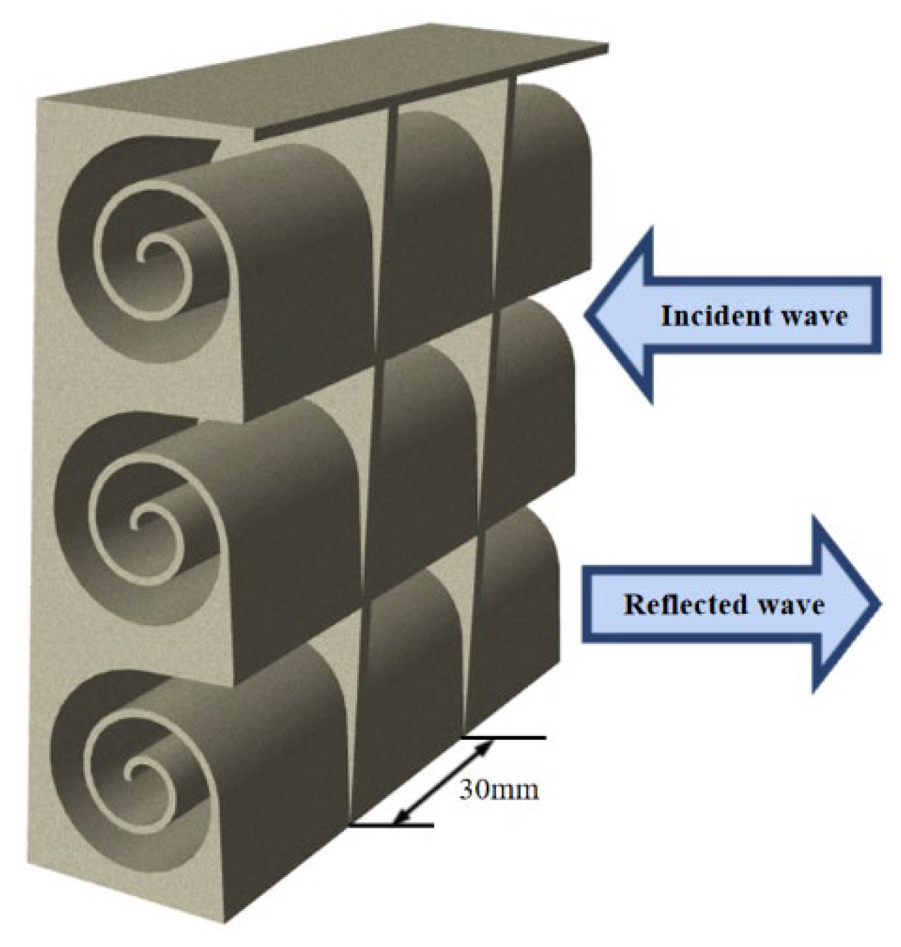
Figure 2.
The cross section of ASCC in the xy-plane.
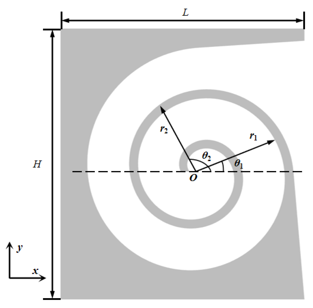
Figure 4.
The cross-section of the FE model.
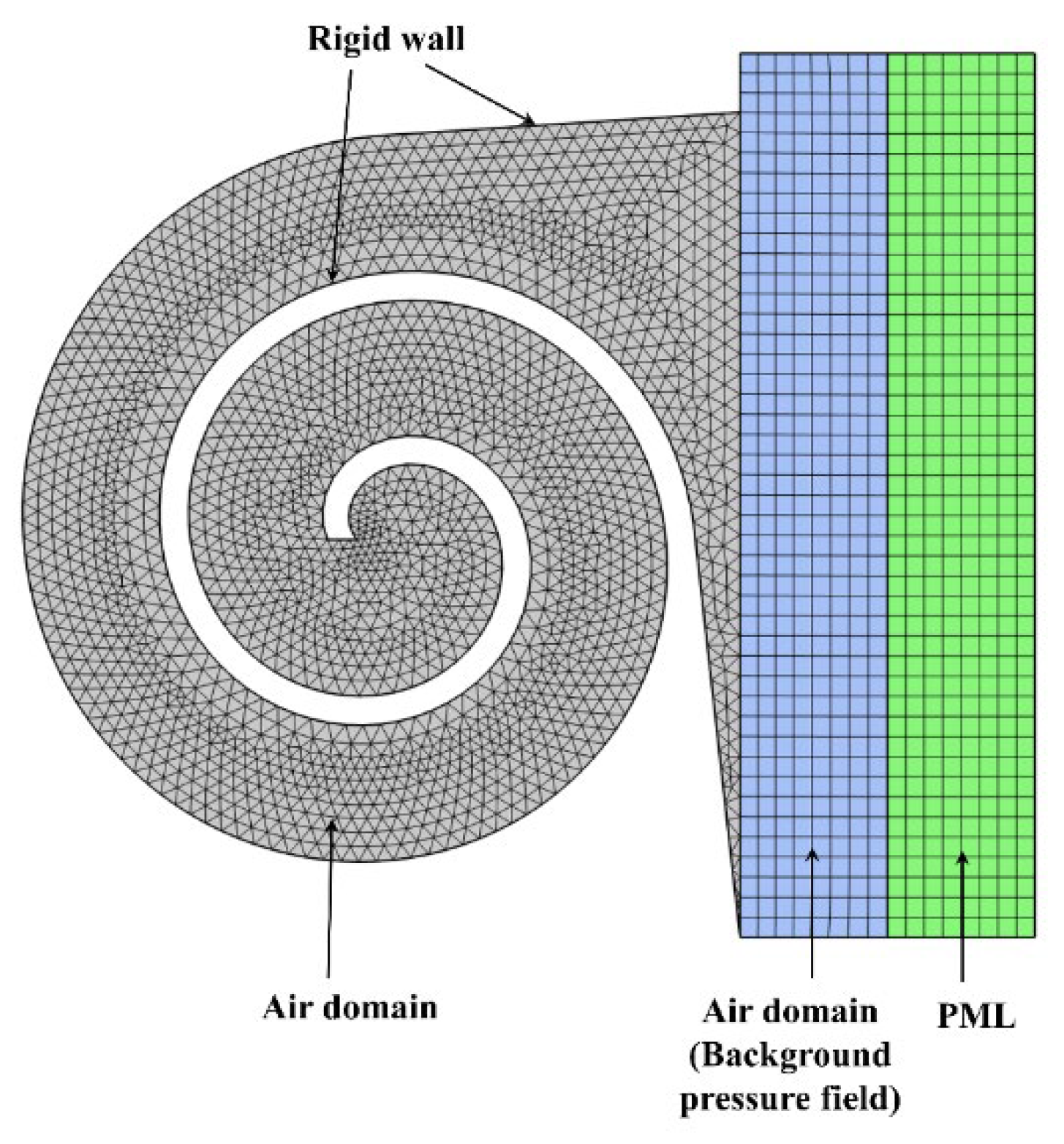
Figure 5.
Sound absorption coefficients of the ASCC.
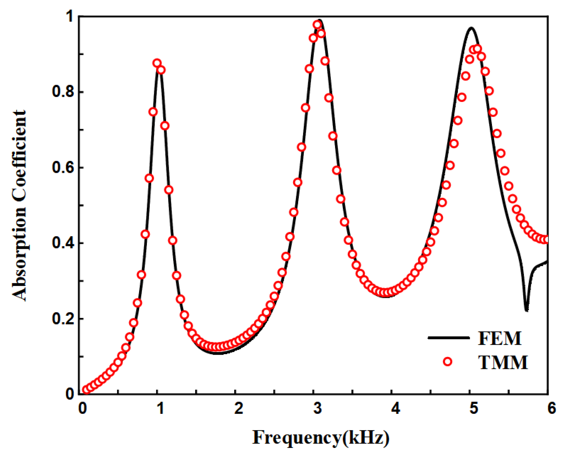
Figure 6.
(a)Sound pressure (b) total power density at absorption peaks.
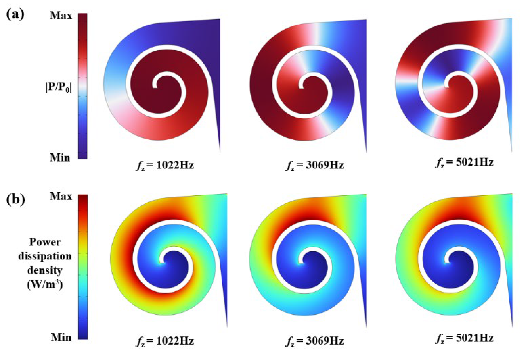
Figure 8.
(a) The cross section (b) sound absorption coefficients. (c) phase variation of the reflection coefficient (d) Argand diagram for 0-3000 Hz (e) Argand diagram for 3000-6000 Hz.
Figure 8.
(a) The cross section (b) sound absorption coefficients. (c) phase variation of the reflection coefficient (d) Argand diagram for 0-3000 Hz (e) Argand diagram for 3000-6000 Hz.
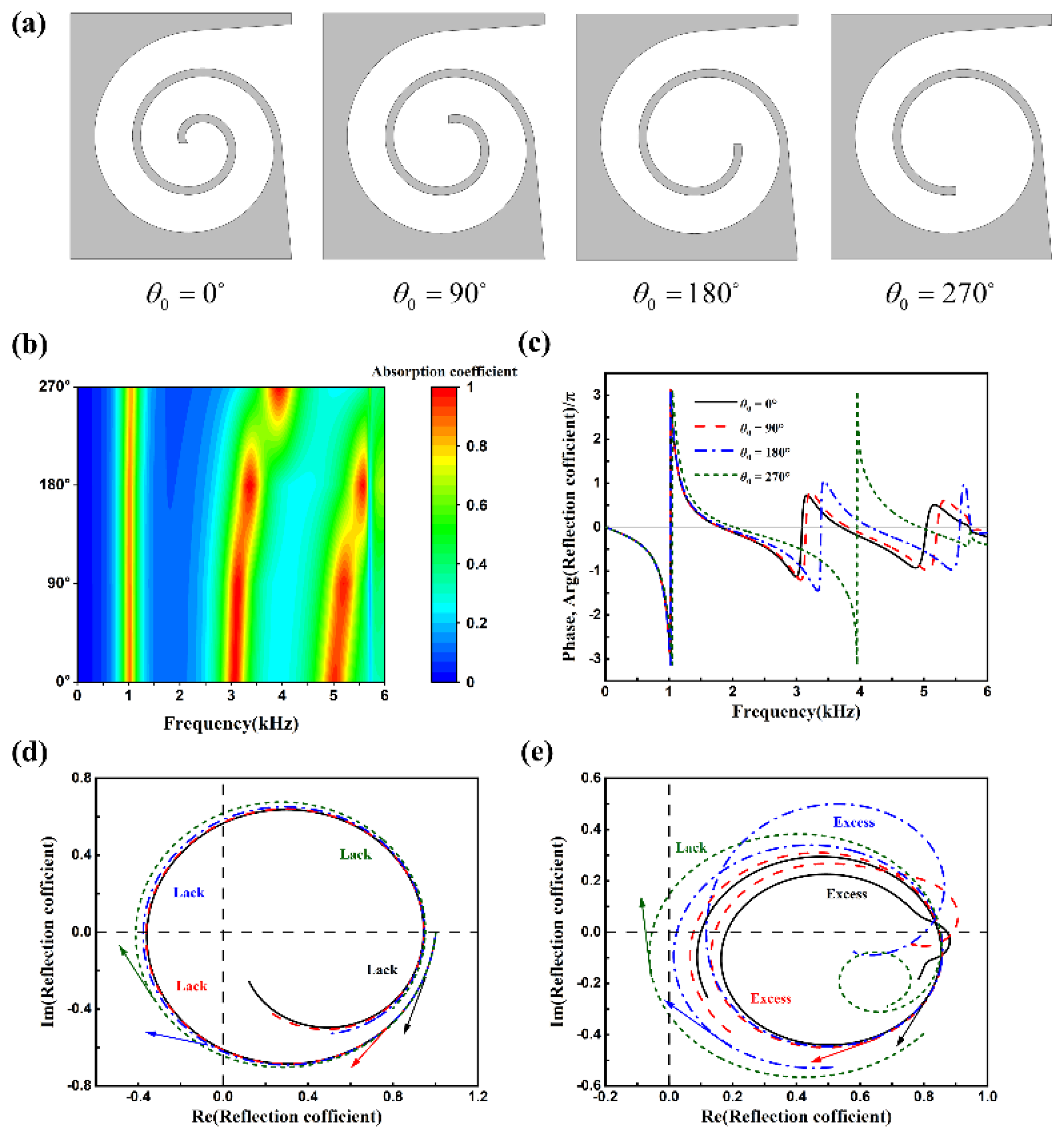
Figure 9.
(a) Experimental facility; (b) sample positioned in impedance tube. (c) samples with two different geometric parameters.
Figure 9.
(a) Experimental facility; (b) sample positioned in impedance tube. (c) samples with two different geometric parameters.
Disclaimer/Publisher’s Note: The statements, opinions and data contained in all publications are solely those of the individual author(s) and contributor(s) and not of MDPI and/or the editor(s). MDPI and/or the editor(s) disclaim responsibility for any injury to people or property resulting from any ideas, methods, instructions or products referred to in the content. |
© 2025 by the authors. Licensee MDPI, Basel, Switzerland. This article is an open access article distributed under the terms and conditions of the Creative Commons Attribution (CC BY) license (http://creativecommons.org/licenses/by/4.0/).
Copyright: This open access article is published under a Creative Commons CC BY 4.0 license, which permit the free download, distribution, and reuse, provided that the author and preprint are cited in any reuse.


