
Submitted:
14 August 2025
Posted:
14 August 2025
You are already at the latest version
Abstract
State-of-the-art geotechnical and structural analyses commonly rely on finite-element analysis, treating soil and structure models separately. Incorporating the overall stiffness of the structure into the geotechnical model enables more realistic settlement predictions and assessments of founding force distribution, ensuring optimized and cost-effective de-signs. Although stiffness increases with building height, the effective contribution to set-tlement control is limited to a finite number of storeys, making the internal stiffness dis-tribution more relevant than the construction method itself. Reliable predictions require modeling approaches that realistically represent structural stiffness. This study evaluates various equivalent-model techniques in PLAXIS 3D and SOFiSTiK for their practicability and accuracy and explains their application. While simplified methods can adequately capture total stiffness under uniform distribution, constructing a full 3D model may be faster or more practical than elaborate simplifications requiring extensive setup and post-processing. Moreover, the construction sequence and evolving stiffness during the build, as well as time-dependent effects like creep and limit-state-dependent stiffness changes within structural elements, significantly influence settlements. A 3D structural model allows these factors to be accounted for comprehensively. Therefore, whenever fea-sible, geotechnical settlement analyses should employ full 3D structural models.
Keywords:
soil‐structure interaction
; settlement calculation
; FEM
1. Introduction
In practical geotechnical analysis, the assessments of settlement troughs are often carried out by modeling the foundation slab alone, while neglecting the stiffness of the superstructure. Although this approach reduces modeling efforts, it can lead to substantial discrepancies in settlement predictions. An alternative is to include the structural system as part of the geotechnical model, thereby achieving a more realistic representation of soil–structure interaction [1,2].
Preliminary studies comparing two construction types, frame-type and wall-type buildings, have shown that neglecting the superstructure results in significantly increased deformations, both in terms of absolute settlements and differential settlement values, when compared to a full 3D reference model. These differences are not merely quantitative; they also affect the load redistribution within the structure, which can lead to misleading conclusions in design. This underscores the necessity of representing superstructure stiffness adequately in geotechnical models.
Despite its relevance, the detailed modeling of structural elements within geotechnical simulations is often considered too time-consuming and complex for everyday engineering tasks. To address this issue, various simplified substitute models have been proposed in the literature to approximate the effect of superstructure stiffness. Based on the methodological investigations presented in [3], the present study compares several of these modeling strategies and their influence on the differential settlements
2. Model types
The structural models developed in this study were designed to represent a broad range of typical building configurations and associated stiffness distributions. The models differ in both their geometric layout and structural design. Two fundamental structural systems are considered: a frame-type structure, characterized by low stiffness and relying on columns as vertical load-bearing elements, and a wall-type structure, which includes load-bearing interior walls and provides significantly higher overall stiffness.
Within each of these systems, two basement configurations are investigated: a “small basement,” whose areal dimensions corresponds to that of the superstructure, and a “large basement,” where the foundation slab extends laterally beyond the building outline. In addition, two further variants are included, where an intermediate soft storey is introduced. This configuration, with an open ground floor and increased storey height, aims to reflect a common design situation in practice, such as entrance foyers or open retail areas, which significantly reduce local shear and bending stiffness. An overview of all six model variants is shown in Figure 1.
All buildings are 15-storey structures with a constant floor height of 3.5 m. The floor plan dimensions range from 54 m to 15 m (small) to 69 m × 30 m (large). Floor slabs have a uniform thickness of 28 cm, basement and exterior walls are 30 cm thick, and interior shear walls are 20 cm thick. The foundation slab is modeled with a thickness of 1.75 m, and the columns are 0.5 m × 0.5 m in cross section.
The models were generated without considering construction stages and were subjected exclusively to self-weight and a constant live load of 5 kN/m². To reduce computational time, each building was modeled as a quarter-structure by exploiting geometrical symmetry. Boundary conditions include fixed horizontal displacements along the model edges and symmetry planes, as well as a fully fixed base. Groundwater was not considered, and all simulations were performed under drained conditions. All materials were assumed to behave linear elastically (see Table 1). At the interface between basement walls and surrounding soil, a zero-thickness interface was defined to allow for realistic shear transfer. The soil continuum was discretized using 10-node tetrahedral elements with about 33.000. The superstructure was modeled using elastic plate and beam elements to represent its mechanical stiffness in a consistent but simplified manner.

Table 1.
Linear elastic material parameters for the structural and the geotechnical model
| Method | Self weight | Elastic Modulus | Poisons Ratio ν |
| [kN/m³] | [MN/m²] | [-] | |
| Concrete | 25 | 30,000 | 0.2 |
| Soil | 18 | 16 | 0.2 |
In this study, the 3D structural model developed in SOFiSTiK serves as the reference for defining a reliable representation of global structural stiffness. To evaluate whether a corresponding structural model recreated within the geotechnical software PLAXIS can capture the same stiffness characteristics, the building was reconstructed using equivalent structural elements. Since the nonlinear behavior of the soil cannot be adequately represented in SOFiSTiK, a direct comparison between the two modeling environments requires both models to use a linear-elastic soil approximation. Although such an approximation is generally not recommended for geotechnical analyses, as highlighted in [4], it is applied here solely for the purpose of validating the structural response.
Extensive validation was carried out by comparing settlement results from the SOFiSTiK [5] model and the PLAXIS [6] model under identical boundary conditions and soil properties. As shown in Figure 2, the deviation in vertical displacements between both simulations is less than 1%, indicating that the PLAXIS model captures the global structural stiffness with sufficient accuracy for the intended analyses.
3. Influence of Storeys on Structural Stiffness
The literature offers varying opinions and recommendations on how many storeys contribute significantly to the overall system stiffness in the context of soil–structure interaction [7,8]. Especially in high-rise buildings, it can be advantageous to reduce modeling complexity by introducing a so-called "settlement-relevant number of storeys", which is the number of storeys to be considered when estimating structural stiffness.
In general, basement levels should always be included as they are typically constructed with stiff, continuous shear walls and contribute significantly to the overall bending stiffness of the structure. For buildings with inherently high stiffness, such as those with massive shear wall systems, it is common practice to consider two to five additional upper storeys [9]. In contrast, for more flexible frame-type structures, the contribution of upper storeys can often be neglected [10]. In these cases, it is important to assess whether vertical elements such as elevator cores or stairwells provide sufficient shear and bending stiffness to ensure composite action with the floor slabs of the storeys over the building height.
To systematically determine how many storeys contribute meaningfully to the settlement-relevant stiffness, the number of active storeys is gradually reduced in a parametric study. Specifically, storeys are successively removed from a massless structural model, while the applied foundation loads remain constant. The objective is to identify the point at which differential settlements along the x-axis of symmetry begin to change noticeably, which marks the threshold beyond which additional floors no longer contribute significantly to the system stiffness.
The loads applied to the foundation correspond to the support reactions of a separately computed, fully rigid structural reference model developed in SOFiSTiK. These include the self-weight of the superstructure and floor slabs, as well as all live loads defined in the original design scenario (Figure 3)The analysis is based on six structural configurations that differ in global stiffness and basement geometry, as described in Section 2.
The evaluation of the results presented in Figure 4.a (small basement) and Figure 4.b (large basement) illustrates the relationship between the number of active storeys and the resulting differential settlements. The plateau-like regions in the curves clearly indicate that the lower storeys contribute most significantly to the system stiffness relevant for settlement behavior. As a criterion for sufficient stiffness representation, a deviation of less than 0.5% from the full reference solution is used.
In the case of models with a small basement footprint, it is evident that the lower three to four storeys dominate the structural stiffness contribution—regardless of the construction type (frame or wall-type).
However, further observations from the remaining models reveal that the variation of stiffness across storeys within a building can have a major impact on the number of settlement-relevant storeys. For instance, in model wall-type with large basement, the stiff basement levels already contribute significantly to reducing excessive settlements. However, these alone are not sufficient to reach the required accuracy. Only when up to eight additional stiffer storeys above the basement are included the deviation from the reference model falls below the 0.5 % threshold.
Another notable effect can be observed in model wall-type with small basement and soft intermediate floor. This model features a nearly constant stiffness throughout, except for a soft storey inserted at ground level. As a result, a distinct kink appears in the settlement difference curve, clearly marking the threshold of structural contribution. This abrupt drop in stiffness is caused by the soft storey, which, being composed entirely of columns, provides limited shear transfer to the adjacent floors.
Nevertheless, upper storeys above this soft level must not be neglected. Their contribution depends on the relative stiffness distribution. In model WALL-LB-SF, for example, a similar kink is visible, but the stiffer upper storeys are still found to significantly influence the global behavior, an effect consistent with that observed in the WALL-LB configuration.
4. Substitute Stiffness by Steiner
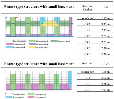
The DIN 4018 [12] outlines a method for calculating a substitute bending stiffness for structures using Steiner’s theorem. In this approach, the superstructure is divided into a set of cross-sections. For each section, the respective moment of inertia is calculated. The global substitute stiffness is then obtained by summing up the individual contributions of each storey. and cross-sectional properties . The substitute bending stiffness is given by:
Here, is the total number of storeys, is the number of effective storeys, and is a reduction factor accounting for reduced connection stiffness and can be calibrated based on the storey height or connection details [13]
To apply this inherently two-dimensional approach to a three-dimensional foundation slab, the substitute stiffnesses determined from each cross-section are projected onto a participating slab width. This is done following the recommendations in [14], enabling a spatially resolved representation of the stiffness distribution. The result is a stiffness map over the foundation area (Table 2) that reflects the structural configuration and interaction effects realistically. The obtained obtained substitute thickness is subsequently implemented in the geotechnical model by utilizing plate elements with a constant stiffness of 30 MPa but varying thicknesses.
5. Substitute Stiffness by Meyerhof
In [14], the concept of substitute structural stiffness is based on the summation of projected moments of inertia of vertical structural elements, modified by a so-called dowel action factor. This factor accounts for the fact that the shear connection between walls and floor slabs is typically much stronger than between columns and slabs.
The dowel action factor is greater than one and depends on the relative stiffness of the structural elements above ( and below ( the objected floor slab. The distribution of stiffness is thus captured by comparing the respective moments of inertia across adjacent floors. The geometry is considered by comparing the slab dimensions to its field width and the total number of spans in the assumed cross-section.
While Meyerhof’s formulation offers clear definitions for calculating substitute stiffness in frame-type structures (columns), it provides no explicit procedure for systems with continuous, shear-connected walls. To address this limitation and enable the inclusion of such walls in the present study, each continuous wall is idealized as a column with an equivalent cross-section. This equivalent column is assigned width b and a thickness d, thereby allowing it to be included in the substitute stiffness summation consistent with Meyerhof’s method. This idealization facilitates a unified treatment of both skeleton and wall-type buildings within a common substitute stiffness framework, while still acknowledging the enhanced shear transfer capacity of continuous wall systems.
In contrast, if the wall is not rigidly connected to the floor slab, such as infill panels in frame-type structures, DIN Technical Report 130 [8] provides a procedure for estimating the substitute bending stiffness. In this case, the total bending stiffness of the structural system is calculated as the sum of three components: the bending stiffness of the foundation system,the bending stiffness of the infill wall, and the bending stiffness of the skeletal frame, typically modeled as a single-storey frame.
To apply this inherently two-dimensional approach to a three-dimensional foundation slab, the substitute stiffnesses determined from each cross-section are projected onto a participating slab width. This is done following the recommendations in [13], enabling a spatially resolved representation of the stiffness distribution. The result is a stiffness map over the foundation area (table 2) that reflects the structural configuration and interaction effects. The obtained substitute thickness is subsequently implemented in the geotechnical model by utilizing plate elements with a constant elastic modulus of 30 MPa but varying thicknesses. The model itself is massless and subjected to the support reactions obtained from the rigid reference model.
Table 3.
Projected substitute stiffness on the foundation slab, according to Meyerhof, obtained as substitute thickness for individual cross sections.
Table 3.
Projected substitute stiffness on the foundation slab, according to Meyerhof, obtained as substitute thickness for individual cross sections.
 |
6. Beam and Plate Model
The so-called Beam and plate model adopted by Werkle and Slongo [16] provides a fast and effective procedure of incorporating wall stiffness into settlement analysis. The core idea is to replace the load-bearing walls of a building—those that are rigidly connected to the foundation slab—by equivalent vertical beam elements (see Figure 5). These beam elements are assigned the same cross-sectional and material properties as the original walls.
In practical implementation, the structural walls connected to the foundation slab are replaced by beam elements with an equivalent "substitute height." This height is not derived directly from the actual storey height but is calculated based on the moment of inertia of the wall section. The reference axis is shifted to the level of the foundation slab, similarly as the Steiner (parallel axis) component is included—resulting in a substitute height that exceeds the physical wall height. Separate substitute heights were determined for both exterior and interior walls, and for each construction type, frame-type and wall-type structures. To account for openings in the exterior walls, the substitute height is further adjusted by applying an assumption for an opening factor. The model itself is massless and subjected to the support reactions obtained from the rigid reference model. The caluclation and basic assumptions are given in Table 4.
7. Substitute Volume Stiffness
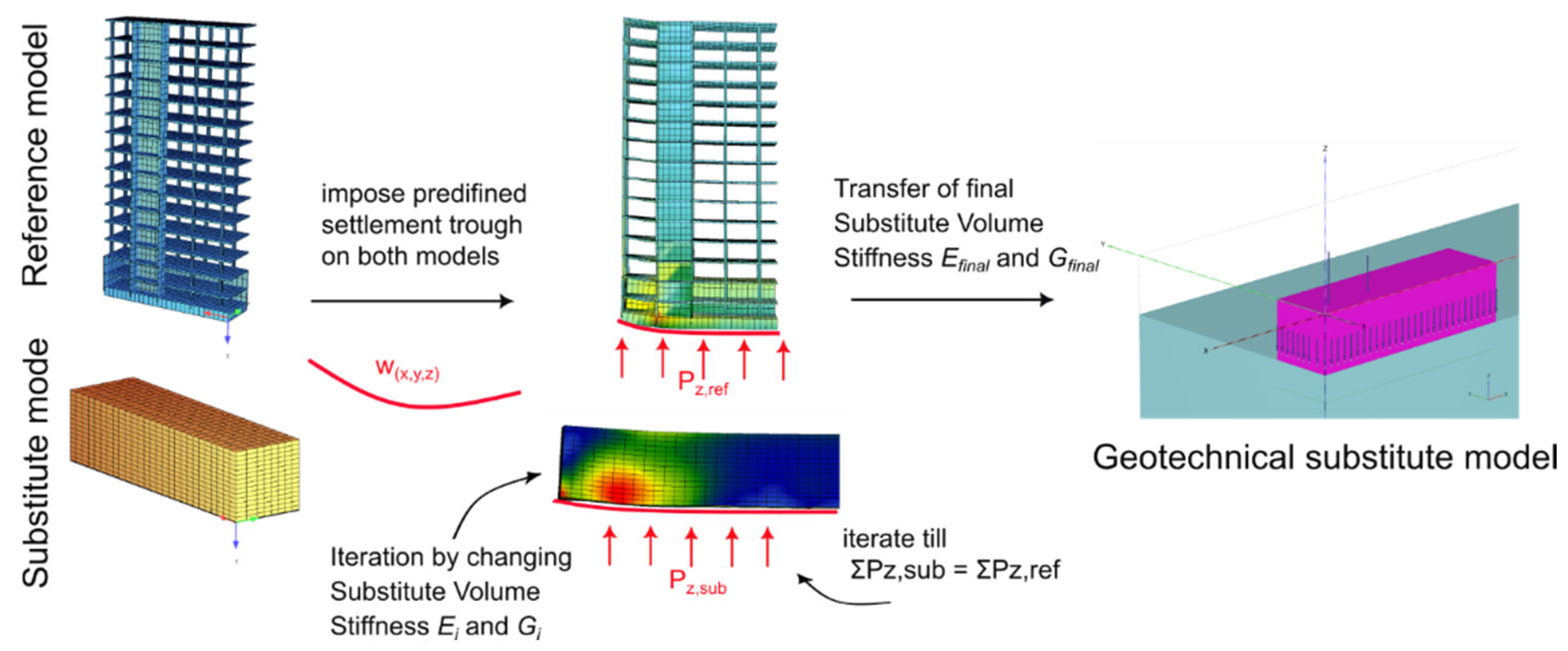
Another approach for approximating the structural stiffness in settlement calculations is the use of a homogenized substitute volume, adapted from [17] in the context of tunnel-induced settlements. Instead of representing the full structural geometry and stiffness, a simplified solid block with the same footprint and height as the basement is introduced into the geotechnical model. This volume is assigned with uniform material properties throughout and is intended to capture the mechanical response of the actual building in a computationally efficient manner. As with other substitute approaches, the model is loaded using the foundation reactions derived from the rigid structural reference model.
In practical application, the substitute volume is generated in parallel to the full 3D reference model. A predefined settlement trough based on field data or synthetic input is then imposed on both models. The material parameters of the substitute volume are iteratively adjusted until the sum of the resulting support reactions matches that of the structural reference model. Once calibrated, the resulting material properties can be transferred to the geotechnical model and used for further settlement analysis.
To address local effects such as punching due to point loads, the location of the point loads was slightly shifted upward (half foundation height). This adjustment resulted in a more realistic load distribution across the substitute volume. The final iteration derives a substitute stiffness of 2910 MN/m² for the frame type building and 9690 MN/m² for the wall type building, showing the clear difference between these two building types.
Figure 6.
Workflow for the substitute volume stiffness iteration.
8. Knot Dependent Substitute Stiffness (Force Method)
The approach introduced by Sommer [18] calculates the substitute bending stiffness by applying the force method. The technique enables the determination of a node-specific substitute stiffness by imposing a unit displacement at each support node. From this, an equivalent substitute thickness can be derived.
Initially, the foundation slab is idealized as a grid of continuous beams, supported by a defined number of nodes in both the x- and y-directions as illustrated in Figure 7. In parallel, the full 3D structural model is rigidly supported at the same nodal pattern. A unit vertical settlement s is then imposed at each support node of the rigidly supported 3D model. The resulting reaction force at each node reflects the local stiffness contribution of the superstructure—larger values are typically found beneath stiff structural cores, whereas smaller forces occur under isolated columns.
The force obtained from the 3D model is then applied conceptually to the corresponding node in the beam-grid system. Using the force method, the equivalent bending stiffness at that location can be obtained.
This calculation is performed successively for each support node, resulting in a distributed map of substitute bending stiffness values across the slab. These stiffnesses are subsequently converted into equivalent substitute slab thicknesses. An example of this thickness distribution for a frame-type structure is shown in Figure 8. The location of the structural cores is clearly identifiable by locally increased substitute thicknesses (e.g., 4.01–4.13 m), illustrating the spatial variation in structural stiffness.
9. Discussion
To evaluate the influence of different modeling approaches on the simulation of structural stiffness within geotechnical settlement analyses, several methods were tested and compared. Figure 9 provides an overview of the resulting differential settlements for both wall-type and frame-type buildings, using various simplifications and modeling strategies.
These include a detailed 3D structural model as reference, a model of the foundation plate without any superstructure, and multiple substitute stiffness approaches: derived using the Steiner method, the Meyerhof method, a node-specific (force-based) calculation, as well as volume-averaged and beam–plate simplifications.
The objective of this comparison is to assess how well each approach captures both global and local settlement behavior, and how suitable they are depending on the structural system and the modeling objective. The findings are discussed in detail below, and a qualitative assessment is provided in Table 5.
Among the tested approaches, the substitute stiffness derived by the Steiner method provides the best global agreement for frame-type and wall-type structures. It captures absolute settlements well in central slab regions but overestimates stiffness near stiff core areas, leading to inaccuracies in curvature representation.
The substitute stiffness derived by Meyerhof method yields moderate results. While the general shape of the settlement trough is preserved, it tends to underestimate stiffness, particularly in skeleton structures. The method performs better for wall-type buildings but cannot reproduce local deformation effects accurately.
The Force method based on knot specific stiffness response offers good agreement for both structure types and enables spatially varying stiffness representation. By deriving stiffness from unit settlements and reaction forces, it better captures local effects such as core stiffness. It is particularly suitable for automated evaluations and detailed interpretation of stiffness distribution, though refinement may be needed in highly concentrated stiffness zones.
The Substitute volume model is well suited for wall-type buildings. It effectively reproduces both the global settlement shape and the edge flattening, resulting from vertically extended stiffness (frame action). However, in frame-type buildings with localized stiffness (e.g., cores), the homogeneous stiffness model is less accurate.
The Beam–plate model performs very well at the slab edges and captures multi-storey frame action. It is ideal for wall-type structures but underestimates stiffness in column-dominated skeleton buildings.
In summary, the Steiner and the Force method-based analysis perform well globally, Meyerhof is limited by core effects, and the Substitute volume model as well as Beam–plate approaches best reflect frame behavior and edge conditions.
A qualitative evaluation of the methods is shown in table 5.
10. Conclusions
This study deals with the bearing capacity and settlement behavior of buildings, focusing on different methods to include the stiffness of the superstructure in soil–structure interaction. Both simplified geometric models and analytical methods for calculating substitute stiffness were investigated.
The comparison between frame-type and wall-type structures shows that the distribution of stiffness within the building has a strong influence on the settlement pattern. One important result is that the number of storeys that affect the settlement can vary. In buildings with uniform stiffness, the lower three to four storeys usually have the biggest influence. But if the basement levels are softer than the rest of the building, more storeys become relevant for settlement.
A key finding is that models that only include the foundation slab without superstructure stiffness often lead to large differences compared to full 3D models. The performance of each method depends on the type of structure and how the stiffness is distributed.
For wall-type structures, the tested methods show very good agreement with the reference model. Local effects, like the change in curvature near the edge of the slab, are captured well, except for the method using substitute thicknesses (force method), which is less accurate in that area.
The situation is different for frame-type structures. Buildings with central stiff cores show large local differences in settlement, which cannot be captured well by simplified models. The stiffness concentration in the core leads to a distinct deformation shape. A better match can be achieved by reducing the shear stiffness in the core or by including the basement structure as part of the model.
In general, the total stiffness of the structure can be represented well with simplified methods, if the stiffness is evenly distributed. However, building a 3D model for geotechnical analysis may take time, but it can be faster or more practical than using complex simplified methods that also require a lot of preparation and post-processing.
Also, the construction process has a strong influence: both the sequence of loading and the development of structural stiffness over building process must be considered. Time-dependent effects like creep, as well as changes in stiffness under service loads, are also important. A 3D model that includes the actual structural elements allows these effects to be considered properly. All these points lead to a clear recommendation: use a 3D structural model in geotechnical settlement analysis whenever possible.
Acknowledgments
This study was conducted within the framework of the collective research project Agile Structural Design for Resource-Responsible Construction, funded by the Austrian Research Promotion Agency (FFG) under project number FO999913808, and supported by the TU Graz Open Access Publishing Fund.
References
- Felic, H. Geostructural Finite Element Analysis of Soil-Structure-Interaction Problems. Master´s Thesis, Graz University of Technology, 2022. [Google Scholar]
- ARSLAN, Eylem, et al. The role of utilizing load in different cases while numerical modeling of multi-story buildings on alluvial stratum: A comparison study. Arabian Journal for Science and Engineering 2024. 49. Jg., Nr. 10, S. 13845-13860. [Google Scholar]
- Stummer, S. Einfluss der Gebäudesteifigkeit auf die Setzungsberechnung und praxisorientierte Anwendungsempfehlungen. Master thesis, Institut für Betonbau, Technische Universität Graz, 2025. [Google Scholar]
- Wallner, C., Tschuchnigg, F.,; Schlicke, D. Die Grenzen des linear elastischen Baugrunds in der Boden-Bauwerk-Interaktion. Beton-und Stahlbetonbau 2025. [Google Scholar]
- SOFiSTiK. HASE – Halbraumanalyse für statische Boden-Struktur-Interaktion; 2023. [Google Scholar]
- Brinkgreve, R., Engin, E.,; Swolfs, W. PLAXIS 3D 2023 reference manual; Delft, Netherlands, 2013. [Google Scholar]
- Fischer, D. Interaktion zwischen Baugrund und Bauwerk: Zulässige Setzungsdifferenzen sowie Beanspruchung von Bauwerk und Gründung; Kassel: Kassel Univ. Press, 2010; Chapter 9. [Google Scholar]
- DIN-Fachbericht 130. Wechselwirkung Baugrund/Bauwerk bei Flachgründungen; Berlin: Beuth-Verlag, 2003. [Google Scholar]
- Muhs H. and Weiss K. Die Berechnung der Bauwerkssteifigkeit von Hochhäusern aus den Ergebnissen von Setzungsbeobachtungen," in Die Bautechnik 40. Jahrgang: Heft 1-12, Berlin: Wilhelm Ernst und Sohn, 1963.Netzel, D. (1972).
- NETZEL, Dieter. Beitrag zur wirklichkeitsnahen Berechnung und Bemessung einachsig ausgesteifter, schlanker Gründungsplatten. 1975.
- Heil H. and Breth H. Der Einfluß der Steifigkeit von Stahlbetonskelettbauten auf die Verformung und die Beanspruchung von Gründungsplatten auf Ton. 1971. [Google Scholar]
- DIN 4018 Beiblatt 1:1981-05. Baugrund; Berechnung der Sohldruckverteilung unter Flächengründungen; Erläuterungen und Berechnungsbeispiele; DIN Deutsches Institut für Normung e.V, Berlin.
- Schindler, S. Monitoringbasierte strukturmechanische Schadensanalyse von Bauwerken beim Tunnelbau, 1st ed.; Aachen: Shaker, 2014. [Google Scholar]
- FÜR STAHLBETON, Deutscher Ausschuss. Hilfsmittel zur Berechnung der Schnittgrößen und Formänderungen von Stahlbetontragwerken; Deutscher Ausschuss für Stahlbeton, Heft 240. 1991.
- MEYERHOF, GEORGE GEOFFREY. Some recent foundation research and its application to design. The Structural Engineer 1953. 31. Jg., Nr. 6, S. 151-167.DIN Fachbericht 130.
- WERKLE, Horst; SLONGO, Lukas. Modeling of soil-structure interaction in the finite element analysis of foundation plates. BAUTECHNIK 2018. 95. Jg., Nr. 9, S. 607-619..
- Rampello S., Callisto L., Viggiani G., and Soccodato F. M. Evaluating the effects of tunnelling on historical buildings: the example of a new subway in Rome / Auswertung der Auswirkungen des Tunnelbaus auf historische Gebäude am Beispiel einer neuen U-Bahnlinie in Rom. Geomechanics and Tunnelling 2012, 5, 279–299. [Google Scholar]
- Sommer, H. Beitrag zur Berechnung von Gründungsbalken und einseitig ausgesteiften Gründungsplatten unter Einbeziehung der Steifigkeit von Beitrag zur Berechnung von Gründungsbalken und einseitig ausgesteiften Gründungsplatten unter Einbeziehung der Steifigkeit von rahmenartigen Hochbauten, Dissertation, Darmstadt. 1965. [Google Scholar]
Figure 1.
Overview of structural model configurations and the geotechnical model size (left). Top row (from left to right): Frame-type structure with small basement (Frame-SB); wall-type structure with small basement (Wall-SB); wall-type structure with small basement and soft intermediate floor (Wall-SB-SF). Bottom row (from left to right): Frame-type structure with large basement (Frame-LB); wall-type structure with large basement (Wall-LB); wall-type structure with large basement and soft intermediate floor (Wall-LB-SF).
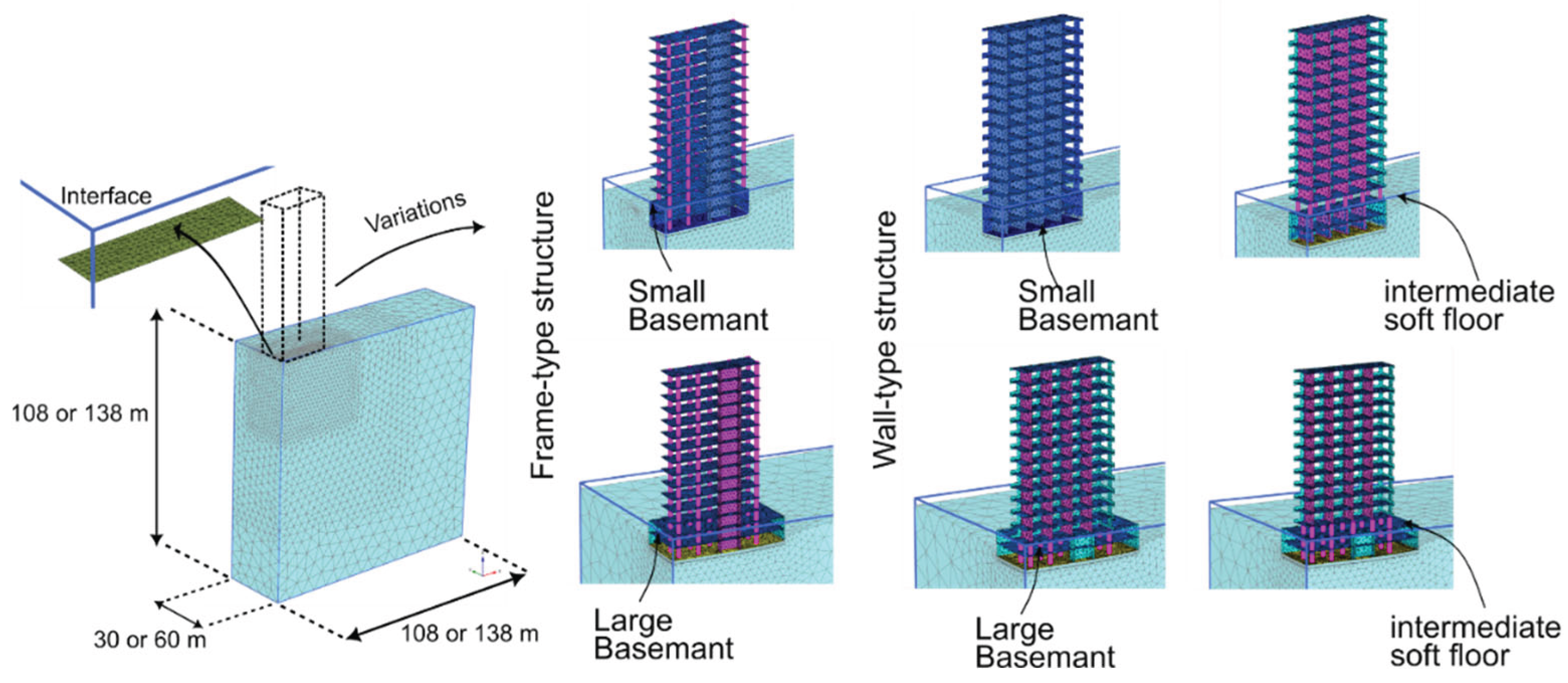
Figure 2.
Comparison of settlement distributions between PLAXIS and SOFiSTiK models for Frame-SB under linear-elastic soil assumption. The vertical displacements (uz) from both models show high agreement, with deviations of less than 1%. This confirms that the structural stiffness of the SOFiSTiK reference model is accurately reproduced in PLAXIS, enabling consistent evaluation of soil–structure interaction effects.
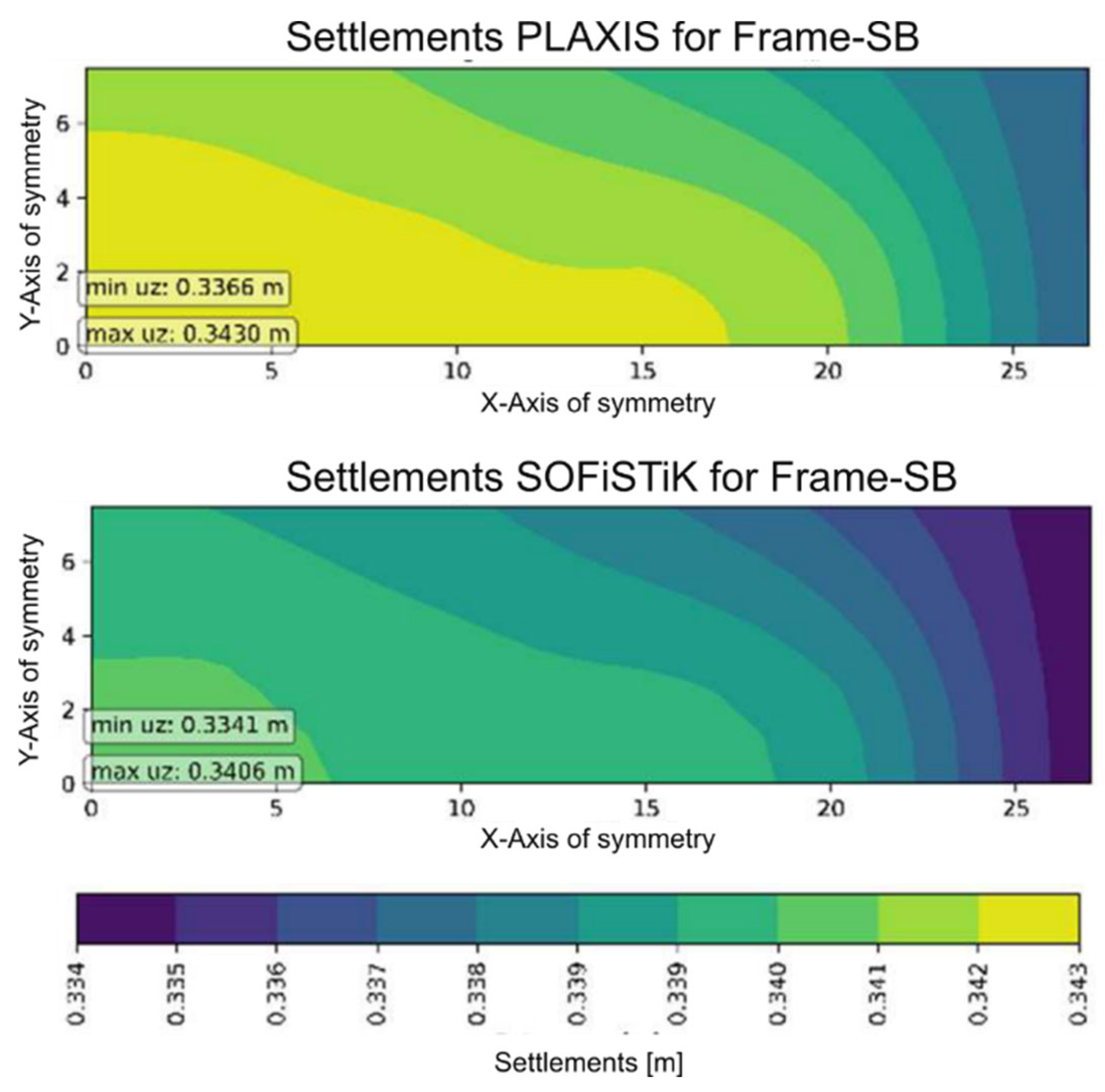
Figure 3.
Method of successive reduction of active (massless) floors for the investigation of contributing floors under constant load (Point loads from structural reference model)
Figure 3.
Method of successive reduction of active (massless) floors for the investigation of contributing floors under constant load (Point loads from structural reference model)
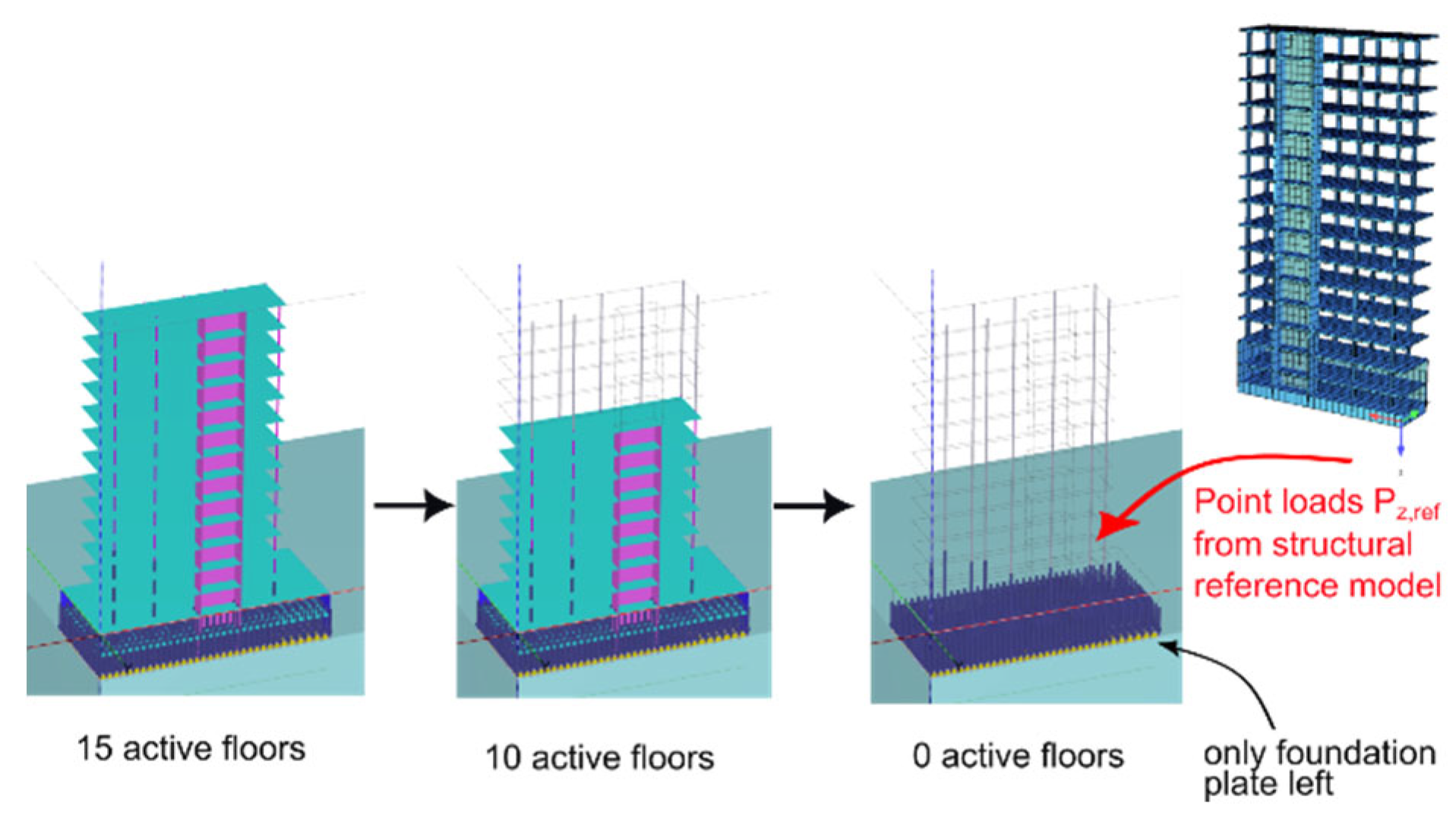
Figure 4.
Contributing floors analysis for small basement (a) and large basement (b) wall-type, frame-type and intermediate soft floor models including the suggested threshold value for active participation.
Figure 4.
Contributing floors analysis for small basement (a) and large basement (b) wall-type, frame-type and intermediate soft floor models including the suggested threshold value for active participation.
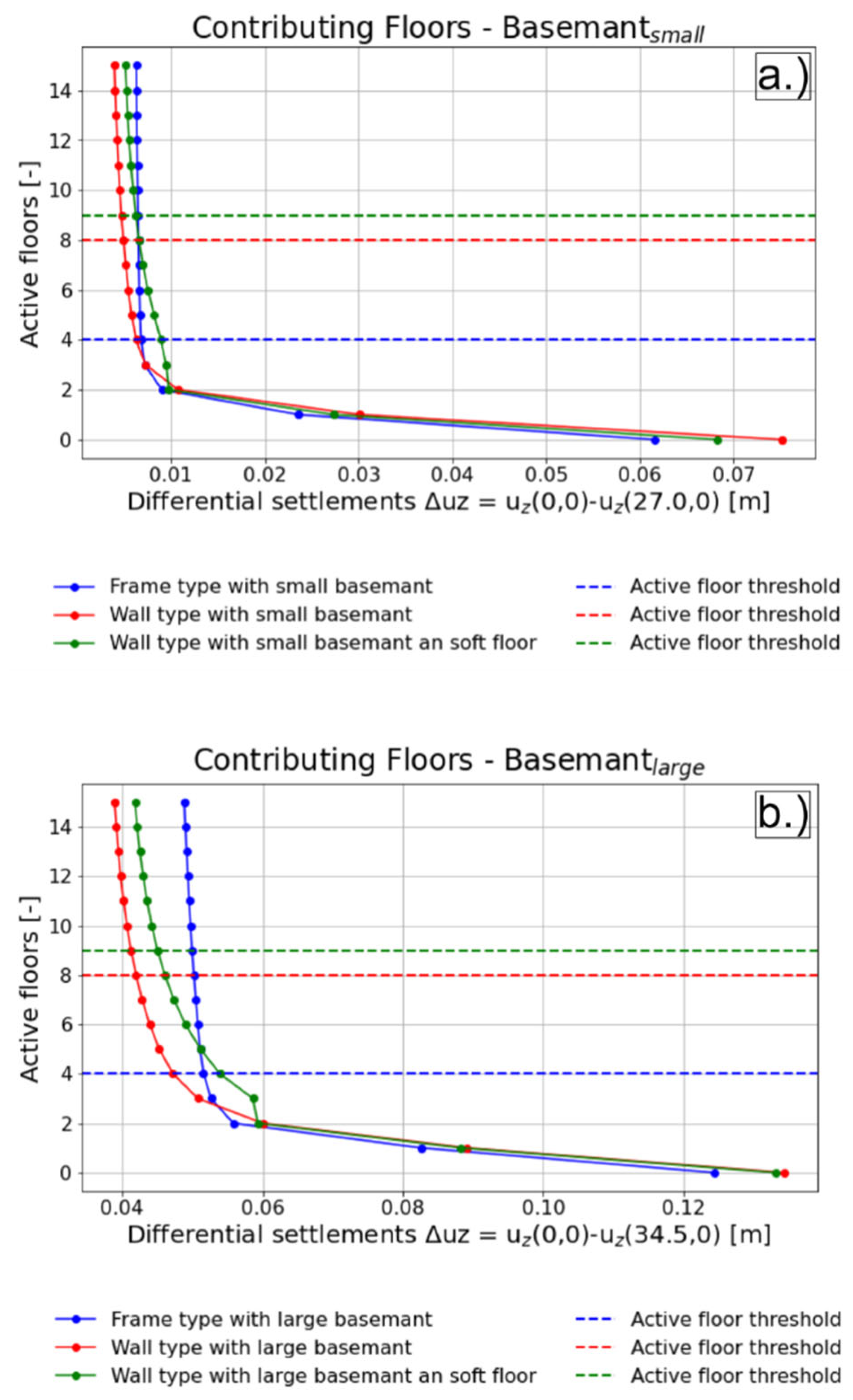
Figure 5.
Substitute beam-plate model in PLAXIS 3D, representing the vertical structural components as beams.
Figure 5.
Substitute beam-plate model in PLAXIS 3D, representing the vertical structural components as beams.
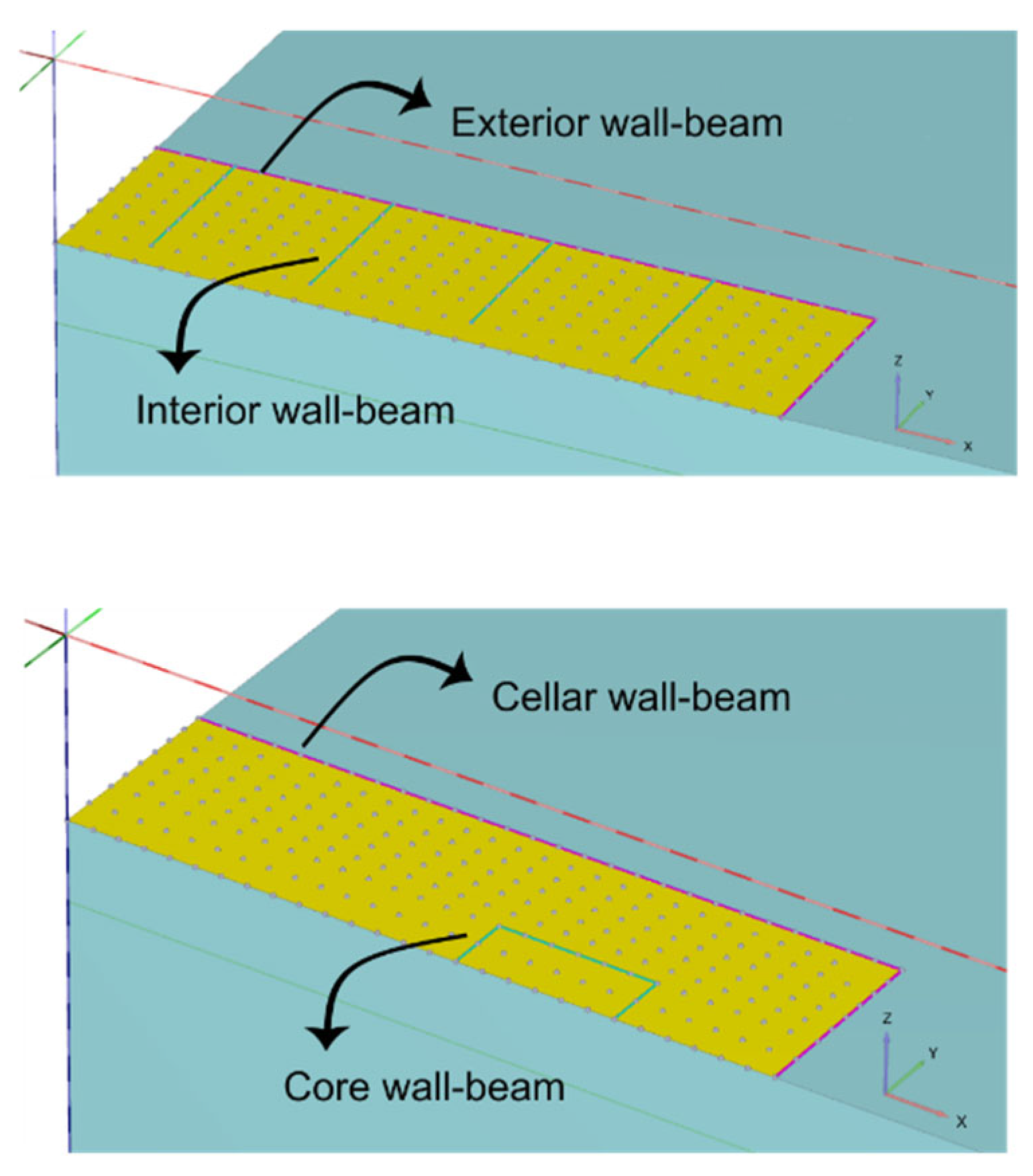
Figure 7.
Workflow for knot dependend susbstittue stiffness by imposing a unit settleement on the reference system applying the reaction forces afterwords on a continous beam system (Ideal slab system approach).
Figure 7.
Workflow for knot dependend susbstittue stiffness by imposing a unit settleement on the reference system applying the reaction forces afterwords on a continous beam system (Ideal slab system approach).
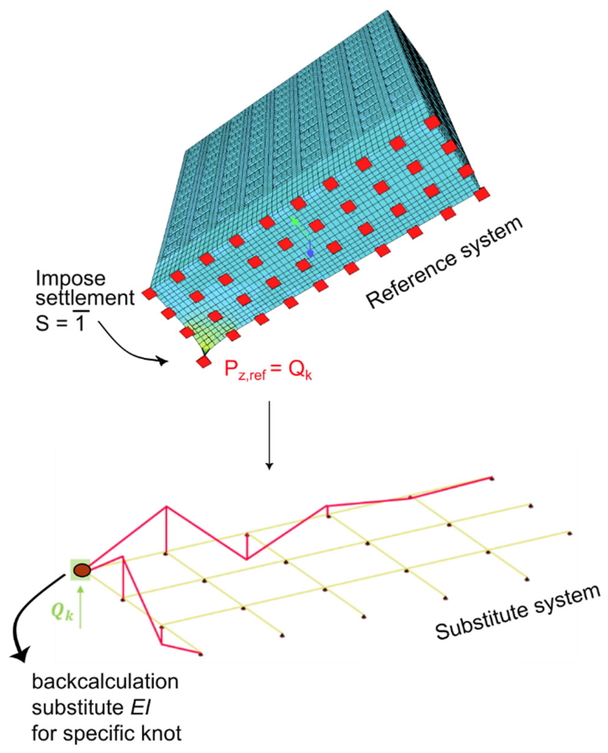
Figure 8.
Distribution of the knot derived substitute stiffness and the final summed up regions for the final application in the geotechnical model.
Figure 8.
Distribution of the knot derived substitute stiffness and the final summed up regions for the final application in the geotechnical model.
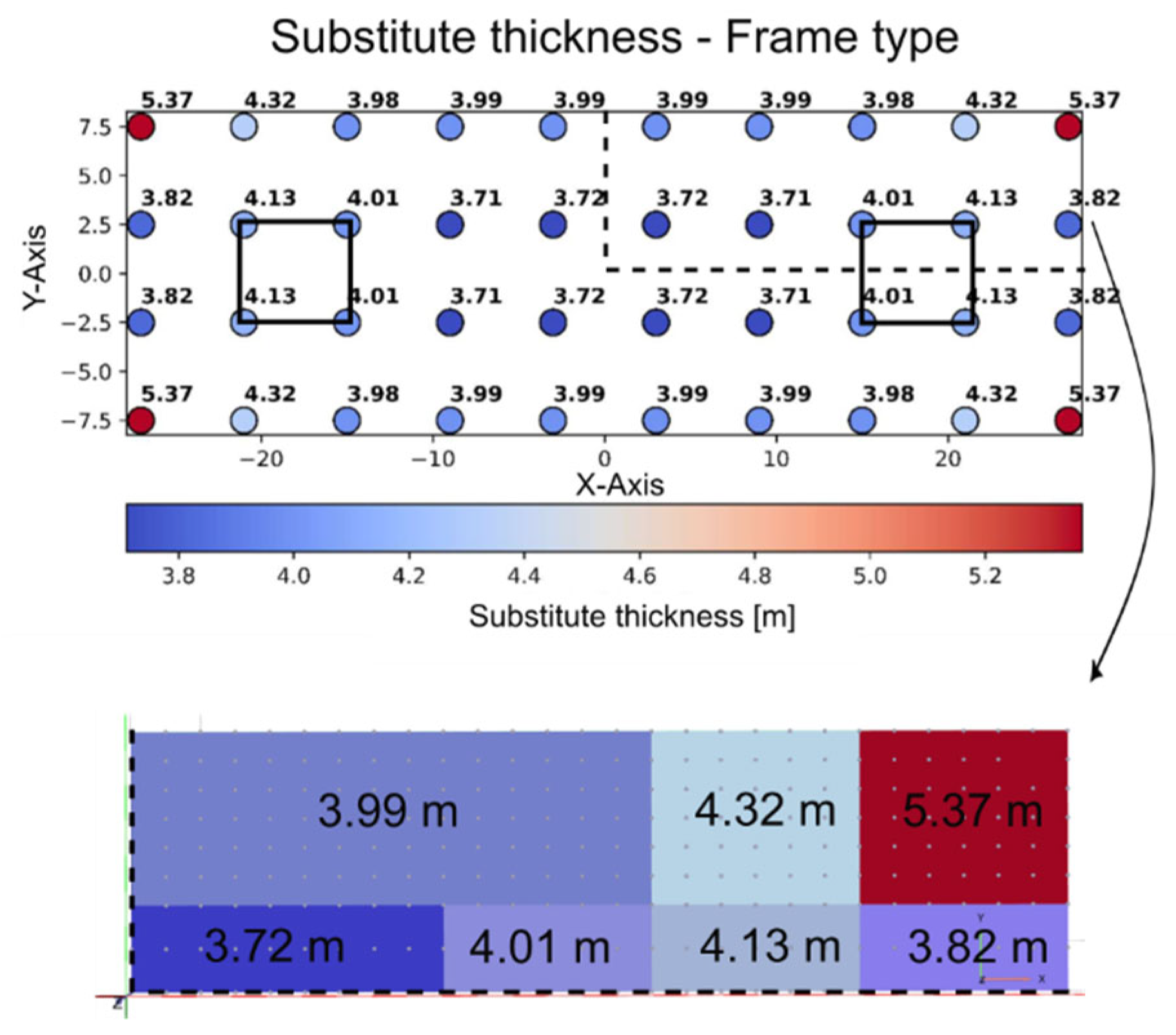
Figure 9.
Structural stiffness representation method overview for wall-type building (a) and frame-type building (b) including a full 3D model approach, the foundation plate without superstructure, Substitute stiffness derived by Steiner, Meyerhof, knot dependent (Force method), smeared using a volume and represented with a beam-plate substitute model.
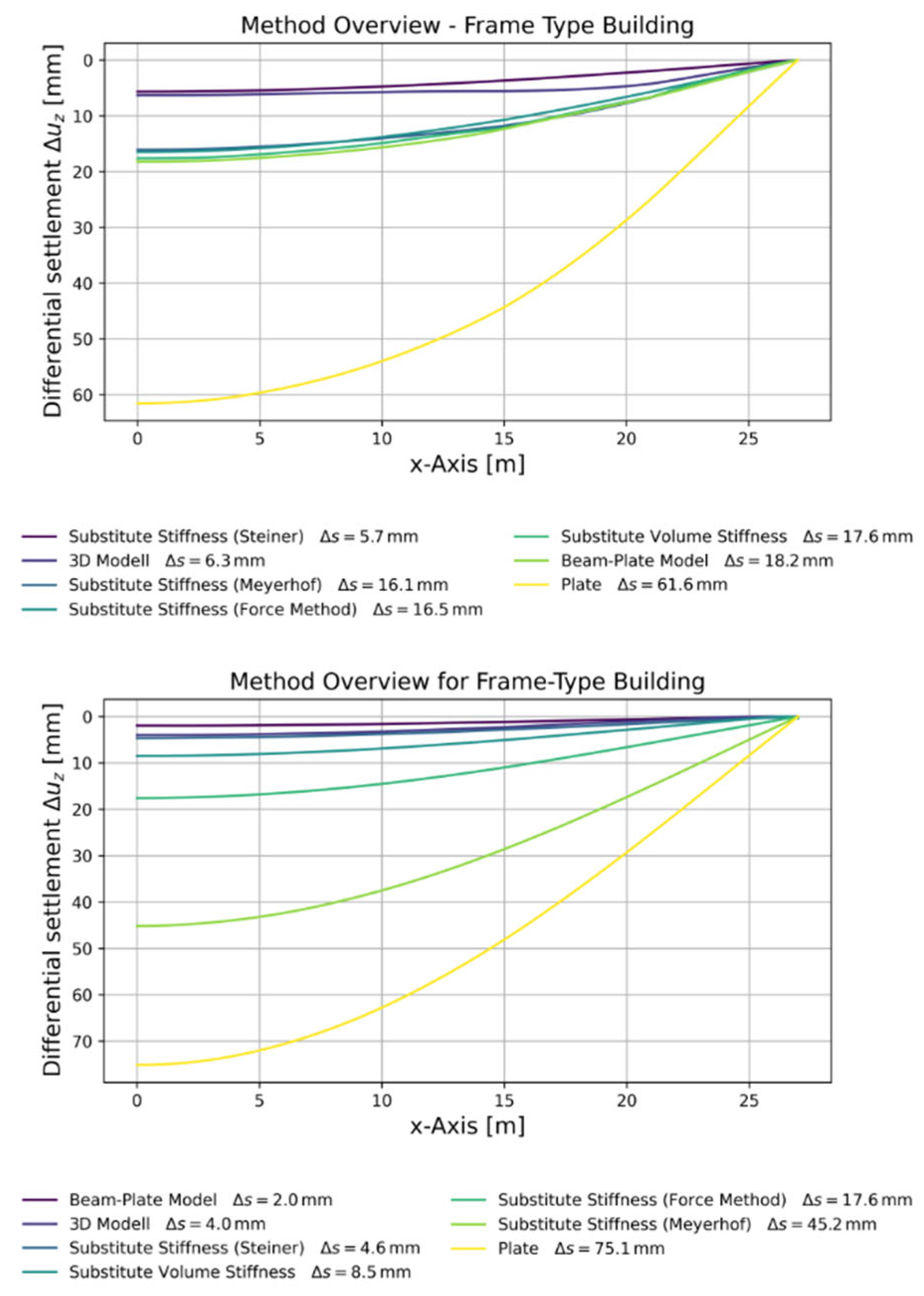
Table 2.
Projected substitute stiffness on the foundation slab, according to Stainer, obtained as substitute thickness for individual cross sections.
Table 2.
Projected substitute stiffness on the foundation slab, according to Stainer, obtained as substitute thickness for individual cross sections.
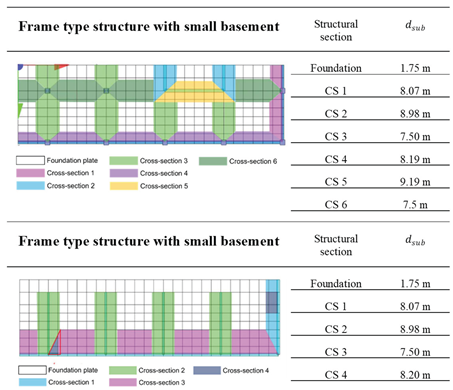 |
Table 4.
Calculation and assumptions for the substitute beam height in the beam-plate model for the frame-type and wall-type model.
Table 4.
Calculation and assumptions for the substitute beam height in the beam-plate model for the frame-type and wall-type model.
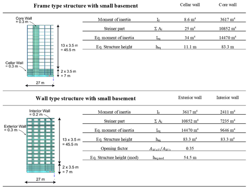 |
Table 5.
Qualitative evaluation of superstructure stiffness modeling methods Recommendation of methods based on structural type, ability to represent local effects (e.g., core stiffness, edge flattening) where ✓✓ = very suitable, ✓ = suitable and ✗ = not recommended.
Table 5.
Qualitative evaluation of superstructure stiffness modeling methods Recommendation of methods based on structural type, ability to represent local effects (e.g., core stiffness, edge flattening) where ✓✓ = very suitable, ✓ = suitable and ✗ = not recommended.
| Method | Frame-type Structure | Wall-type Structure |
Core Behaviour |
Edge Behaviour |
| Substitute Stiffness (Steiner) | ✓✓ | ✓✓ | ✗ | ✓ |
| Substitute Stiffness (Meyerhof) | ✓ | ✓ | ✗ | ✗ |
| Force Method | ✓✓ | ✓✓ | ✓ | ✓ |
| Substitute Volume Model | ✗ | ✓✓ | ✗ | ✓✓ |
| Beam–Plate Model | ✗ | ✓✓ | ✗ | ✓✓ |
Disclaimer/Publisher’s Note: The statements, opinions and data contained in all publications are solely those of the individual author(s) and contributor(s) and not of MDPI and/or the editor(s). MDPI and/or the editor(s) disclaim responsibility for any injury to people or property resulting from any ideas, methods, instructions or products referred to in the content. |
© 2025 by the authors. Licensee MDPI, Basel, Switzerland. This article is an open access article distributed under the terms and conditions of the Creative Commons Attribution (CC BY) license (http://creativecommons.org/licenses/by/4.0/).
Copyright: This open access article is published under a Creative Commons CC BY 4.0 license, which permit the free download, distribution, and reuse, provided that the author and preprint are cited in any reuse.


