Submitted:
14 August 2025
Posted:
15 August 2025
You are already at the latest version
Abstract
The effect of soil nonlinearity on dynamic structure-soil-structure interaction (SSSI) is investigated using a 2D model of two sup-structures supported by rigid foundations embedded in soil layers over elastic bedrock by finite element-indirect boundary element (FE-IBE) coupled method. In the model, the near-field soil and far-field soil, which both can experience nonlinear deformations, are modeled by finite element and indirect boundary element method, respectively. In the parametric analysis, the contribution of linear SSSI and soil nonlinearity, as well as the soil- structure interaction (SSI) of a single structure and structure-structure across interaction , to the combined SSSI effect are assessed. It is shown that the soil nonlinearity reduce shearing relative displacement amplitudes significantly, while it enlarges foundation rotation significantly; both linear SSSI and soil nonlinearity contribute significantly to the combined SSSI, and basically the proportion of linear SSSI is larger; if the adjacent structure is much heavier or the excitation is larger, the influence of soil nonlinearity is larger. In addition, the SSI considering soil nonlinearity accounts for much larger proportion than the across interaction; if the adjacent structure is much heavier, the across interaction may enlarge foundation rotation obviously. In conclusion, SSSI with soil nonlinearity may be significantly different from linear SSSI or SSI with soil nonlinearity.
Keywords:
structure-soil-structure interaction (SSSI)
; soil-structure interaction (SSI)
; structure-structure cross interaction (SSCI)
; soil nonlinearity
; finite element (FE)-indirect boundary element (IBE) coupled method
1. Introduction
In our recently published paper [1], we studied structure-soil-structure interaction (SSSI) in linear range of response by indirect boundary element method (IBEM) and found that it may influence structural response significantly. In this study, a two-dimensional (2D) finite element-indirect boundary element (FE-IBE) coupled method is developed to investigate dynamic SSSI through nonlinear soil. To study the effect of soil nonlinearity, it’s assumed in the model that only the soil can experience nonlinear deformations, while the structures are forced to remain linear, and gapping, sliding or uplift at the foundation-soil interface are not allowed. Our focus will be on the following problems. ①. The SSSI through nonlinear soil can be thought as combined effect of linear SSSI and the contribution of soil nonlinearity. The proportions of linear SSSI and soil nonlinearity in the combined SSSI effect are assessed, and whether energy dissipation of soil nonlinearity can reduce the amplitudes of structural response significantly. ②. The SSSI through nonlinear soil can also be thought as combination of SSI (soil- structure interaction of a single structure) and cross interaction between structures through nonlinear soil. It’s analyzed the proportions of SSI and cross interaction through nonlinear soil in the combined SSSI effect, and whether the effect of cross interaction through nonlinear soil can be safely neglected; in addition, the influence of adjacent structure’s dynamic characteristics on the proportions of each part is studied as well.
Traditionally, it’s assumed that the motion at the base of the structure is taken as equal to the free-field ground motion during earthquakes in the classical method of structural analysis. However, this assumption is correct only for structures constructed on hard or very stiff soil. For structures constructed on soft soil, the base motion is usually different from free-field motion. The work spent for the development of nonlinear strains of the soil around the foundation can consume part of the input wave energy; the radiated and scattered waves from the structure (foundation) and scattered waves between adjacent structures (foundations) alter the motion of the soil and the structure; a rotational component caused by flexible-base on the horizontal motion of the base is added. The complex nonlinear structure-soil-structure interaction during earthquakes may play an important role in the analysis of essential structures. Up to now, design provisions do not provide suggestions to account for SSSI effects. Although some numerical analysis [3,4] and test studies [10,11,12] exist, generalized methodologies for considering the effects of nonlinear SSSI on the seismic demands in urban environments do not exist, and there are fewer bases for developing design codes to provide guidance for considering nonlinear SSSI effects.
Dynamic SSSI in the linear range of response has been studied for several decades. It started with idealized superstructures and foundations with rigorous mathematical solutions. There are a few seminal theoretical studies published by Luco and Contesse [13], Wong and Trifunac [14], Wong [15] and Murakami and Luco [16], in which the necessity of consideration of SSSI effect, whether beneficial or detrimental, is emphasized. Then, the linear SSSI progresses in time to more realistic and complex structural setups solved by numerical methods. Guéguen and Colombi [17] confirmed the clustering effect and found that the variation of the seismic response of the building in the middle of the cluster depends on the azimuth of the seismic source relative to the building cluster. It’s concluded that clustering has an impact on urban effect, calling into question the validity of seismic design, which considers buildings in urban areas as stand-alone constructions, and the interpretation of macroseismic intensity surveys conducted in dense urban areas. Bybordiani and Arici [20] investigated the interacting effects of adjacent buildings using 2D finite element models of 5-, 15-, and 30-story structures. Numerical results showed that neglecting SSSI for neighboring closely spaced high-rise structures or building clusters with a large stiffness contrast would lead to a considerable underestimation of the true seismic demands. The dynamic through-soil interaction between nearby groups of structures is numerically studied by BEM-FEM coupled method [18,19]. It’s shown that SSSI effects on structures with similar dynamic characteristics have been found to be important. The system response can be either amplified or attenuated according to the distance between adjacent buildings, which has been related to dynamic properties of the overall system.
In recent years, some earthquake damage brought out the need to understand the nature of soil nonlinearity and its relationship with dynamic SSI. Energy dissipation by nonlinear soil strains during soil-structure interaction is studied in [22]. The examples of nonlinear soil and foundation responses shown in this paper confirm that the energy entering a building can be reduced significantly before the waves approach and then enter the building. Linear and nonlinear SSI system response of buildings and safety-related nuclear structures are analyzed in [23]. It’s shown that nonlinear SSI predictions can be significantly different from those using linear models, and the differences are greatest for cases with significant nonlinearities. Raychowdhury P [24] studied the seismic response of low-rise steel moment-resisting frame (SMRF) buildings incorporating nonlinear soil-structure interaction. It is observed that the force and displacement demands are reduced significantly when the foundation nonlinearity is accounted for.
With the advance of the numerical techniques and experiment technology, the analysis of nonlinear SSSI is developed in recent years. Vicencio F and Alexander NA [3] used a discrete nonlinear model, in which a nonlinear phenomenological Bouc-Wen model for the soil directly underneath the foundations and linear behavior of buildings are assumed, to evaluate the effect of SSSI. The parametric study showed that there are significant differences in the response to the linear SSSI analysis, and moreover the nonlinear SSSI can produce a greater range of beneficial and adverse behavior for displacement than linear SSSI. Additionally, there is evidence presented that suggest significant differences between nonlinear SSSI and nonlinear SSI analyses. Nonlinear response of tall buildings considering SSSI effect was studied by finite element method [4]. It was concluded that in the case where the soil and structure’s periods were near to each other, the interaction of adjacent structures on increasing nonlinear responses and structural damage indexes was noticeable. Whereas in the case where periods are distant from each other, the interaction of adjacent buildings has a decreasing effect on damage indexes and nonlinear responses and therefore was negligible. The effect of building adjacency is explored by geotechnical centrifuge tests [10]. Spectral comparisons indicate that wave based SSSI effects had little influence on the seismic response of inelastic frame structures, which may be attributed to the dominant effects of energy dissipation associated with inelastic structural and nonlinear nearfield soil behavior, as opposed to dissipation via wave radiation, regardless of motion intensity and spacing between structures. In other analysis of nonlinear SSSI geotechnical centrifuge test [12], it found that SSSI has detrimental impacts on building superstructure response and therefore should be accounted for in the design of closely clustered structures.
Numerical and test studies all confirmed that soil nonlinearity may contribute significantly to the SSI and SSSI. However, existing researches on SSSI through nonlinear soil are fewer and insufficient to provide guidance for structural analysis and seismic design. In this study, we will assess the contribution of soil nonlinearity, linear SSSI, nonlinear SSI and nonlinear across interaction to SSSI through nonlinear soil, and the influence of adjacent structure’s dynamic characteristics and separation distance between structures on the contribution.
In the next section, we present the methodology of 2D FE-IBE coupled method. Then, the method is verified by comparison with published results using other numerical method, followed by numerical results and analysis. Finally, we summarize the principal findings.
2. Methodology
2.1. The Model
As shown in Figure 1, two buildings represented by shear walls with height H1, H2 and width W1, W2, are supported by rigid foundations of any shape embedded in soil layers. Herein we take rectangular rigid foundations, with width W1, W2 and embedment E1, E2, as the example. The separation distance between buildings is b. The ratio of building mass to foundation mass is Mb1/M01, Mb2/M02, and the ratio of foundation mass to soil mass that removed by the excavation is M01/Ms1, M02/Ms2. The fundamental fixed-base frequency of the building is f11 and f21. The superstructure as a whole, can be characterized by its equivalent shear wave velocity in vertical direction βb1=4H1f11 and βb2=4H2f21. The Poisson’s ratios of the superstructures are νb1 and νb2, and the hysteretic damping ratios are ζb1 and ζb2. The material properties of soil layers and bedrock are characterized by Lame constants and Gi, Poisson’s ratio νi, mass density ρi, and damping ratio ζi, from which its shear and compressional wave velocities, βi and αi (i=1, 2, …, n, n+1), can be computed. The seismic wave is incident from the bedrock, at angle θ measured from the horizontal.
In general, the soil and structures can all step into nonlinear deformation stage in moderate or strong earthquakes. Gapping, sliding or uplift may also occur at the foundation-soil interface. However, to study the effect of nonlinear zones in the soil, it’s assumed in the model that only the soil can experience nonlinear deformations, while the structures will be forced to remain linear. In addition, perfect bond exists between the foundations and soil, which means that foundation gapping, sliding and uplift are not allowed in the model.
2.2. FE-IBE Coupled Method
Finite element-indirect boundary element (FE-IBE) coupled method is developed in this paper. As shown in Figure 2, the soil in the far field is modeled by indirect boundary element method called IBE subdomain represented by ΩB. The soil in the near field is modeled by finite element method, which is called FE subdomain represented by ΩF. The width and height of ΩF is W and H, respectively. The common boundary between ΩF and ΩB is S1. The structures (including the superstructures and foundations) are modeled by analytical method. The common boundary between ΩA and ΩF is S2 and S3. ΩF and ΩB are coupled by the displacement compatibility condition and force equilibrium condition on the common boundaries.
2.2.1. The Calculation of IBE Subdomain
The boundary S1 of IBE subdomain is discretized into N segments expressed as sj (j=1,…,N). Accordingly, the soil overlying bedrock is divided into m horizontal sub-layers. Under seismic excitation, the dynamic response of IBE subdomain consists of two parts: the free field response and scattered field response.
For free field response, firstly, the stiffness matrices of the soil sub-layers, [Ej], j=1,2,…, m, and the bedrock, [ER], are constructed and merged into global dynamic stiffness matrix [Ef]. [Ej], [ER] and [Ef] are described in the Appendix. Then, nodal-displacements on the interfaces of the sub-layers can be obtained by the direct stiffness method [27]. After that, the displacement [ufree] and traction [tfree] on boundary S1 can be obtained [27].
For scattered field, the Green’s functions represent the response due to the loads [P2]j (j=1,…,N) acting on S1 applied by FE subdomain. Firstly, the the global dynamic stiffness matrix is formed, which is similar with that in free field response. Then, the displacement Green’s function [gu2]ij and traction Green’s function [gt2]ij [27] in ΩB can be solved to represent the dynamic scattered field displacement and traction of si (i=1,…,N) when unit distributed load is acted on sj (j=1,…,N).
The total responses on boundary S1 of :
Further details about the calculation of IBE subdomain (ΩB) can be found in [27].
2.2.2. The Calculation of FE Subdomain
The soil in FE subdomain is discreted by four-node isoparametric elements. To facilitate the coupling of FE and IBE subdomain through the common boundary S1, the discrete segments sj (j=1,…,N) on S1 of FE subdomain are identical with those on IBE subdomain. The boundary S2 and S3 are divided into N2 and N3 segments expressed as sj (j= N +1,…,N+ N2) and sj (j= N+ N2+1,…,N+ N2+ N3), respectively. In the calculation, firstly, the global stiffness matrix of the FE subdomain [KF] is built, in which the lumped mass matrix and hysteretic damping are adopted. [KF] can be partitioned as
where the subscript s indicates the nodes on common boundary S1, S2, and S3, and u indicates the interior nodes that are not on common boundaries. Under seismic excitation, there are only the interaction tractions [ P1], [P3]and [P4] acting on the common boundary S1, S2, and S3, respectively. It’s assumed that the interaction tractions can be expressed as a set of fictitious distributed loads written as [pF], with pFj on sj (j=1,…,N, N+1,…, N+ N2+ N3). Thus, under seismic excitation, the dynamic response of ΩF is caused by [pF]:
[A] is transformation matrix to convert distributed loads into equivalent nodal loads. us are displacement of the coupling nodes on boundary S1, S2, and S3, while uu are displacement of the interior nodes. Then, we can obtain the dynamic response of each element on ΩF.
To facilitate the coupling, we define the displacement Green’s function [gu1]ij, [gu13]ij, and [gu14]ij to represent the displacement on segment si (i=1,…,N), si (i=N+1,…,N+ N2) and si (i=N+ N2+1,…,N+ N2+ N3), respectively when unit distributed load acting on Sj (j=1,…, N+ N2+ N3). Similarly, traction Green’s function[gt1]ij, [gt13]ij, and [gt14]ijare defined. Thus, the dynamic displacement and traction on boundary S1 of ΩF can be expressed as:
The displacement on S2 of ΩF can be expressed as:
The displacement on S3 of ΩF can be expressed as:
2.2.3. The Calculation of Structures
The superstructures are modeled by shear walls, which deform in pure shear. It’s assumed that the interaction forces acting on S2 and S3 are resultant force of [-P3] and of [-P4], respectively. The displacement [u3]A on S2 and [u4]A on S3 can be expressed as [27]:
in which, . The displacements on the center of rigid foundations o1 and o2 are and, which can be expressed as:
The absolute horizontal and vertical displacements at the top of the superstructures are [27]
in which, , ; and αbj, βbj are equivalent compressional wave velocity and shear wave velocity of the superstructures, respectively.
2.2.4. The Boundary Condition
The displacement compatibility condition on S1 is:
The force equilibrium condition on S1 is:
The displacement compatibility condition on S2 is:
The displacement compatibility condition on S3 is:
Then, Eq. 14 can be expressed as:
in which . Eq. 15 can be expressed as:
in which . Left multiply (16) by ,
(18)- (17),
And then, [P4]can be expressed as:
in which . Left multiply (17) by ,
(21)- (17),
[P3]can be expressed as:
in which . And then, (12) and (13) can be expressed as:
At last, we can get the boundary condition equations by (24) and (25),
The fictious distributed loads [P1]and [P2]acting on the coupling boundary S1 can be obtained by Eq. 26. [P3]and [P4]can be obtained by Eq. 23 and Eq. 20, respectively.
2.3. The Equivalent-Linear Approach in FE-IBE Coupled Method
Equivalent-linear approach is adopted to account for the nonlinearity of the soil in IBE and FE subdomains. It’s assumed that the soil nonlinearity of IBE subdomain is the same with that of the free field, which is guaranteed by a sufficiently large FE subdomain. The equivalent shear module and damping ratio of the IBE subdomain can be estimated by the equivalent-linear site response. Then, the interactive calculations of FE subdomain coupled with IBE subdomain are conducted, in which the soil nonlinearity of FE subdomain is considered and the dynamic response of the IBE subdomain is unchanged. The details of the equivalent-linear approach in the calculation are as follows.
(1) The first calculation of equivalent-linear free field response is conducted with the initial shear modulus μ0 and initial damping ratios ζ0 of the soil layers in IBE subdomain. Then, the maximal shear strains and the equivalent shear strains of each soil layer can be obtained.
(2) New shear modulus μi and damping ratios ζi of each soil layers can be re-calculated by and the relationship between dynamic shear modulus/damping and the shear strains.
(3) Recalculate the dynamic free field response and maximal shear strains γimax, and make a judgment by the maximum allowable error κ (κ=5% in our calculation). If , repeat steps (2) to (3) until ; while if ≤κ, the iterative calculation of the free field motion is finished.
(4) Similarly, the first calculation of dynamic response of FE subdomain is conducted with the initial shear modulus and initial damping ratio of each element in FE subdomain, coupled with IBE subdomain whose parameters are determined in (3). Then, the maximal shear strains γ0max and the equivalent shear strains γ0eff of each element in FE subdomain can be obtained. Similar with steps (2) to (3), the iterative calculations in FE subdomain coupled with IBE subdomains are conducted until.
(5) Finally, output the dynamic response of the structure and the site.
3. Method Validation and Accuracy Verification
To verify the reliability and accuracy of this FE-IBE coupled method, Figure 3 shows a comparison of our results for twin buildings supported by semi-circular rigid foundations with those obtained by indirect boundary element method [27] in linear range of response. The radius of semi-circular rigid foundation is a. The parameters for layered half-space are D/W1=2 (corresponding D/a=4 in [27]), ζR=ζL=3.5%, νR=νL=1/3, and βR/βL=2 and βR/βL=5 for part (a) and (b), respectively. The parameters for buildings are W1=W2=2a, H1=H2=2W1=4a, building relative flexibility ε=4, the mass ratios are Mb/M0=4 and M0/Ms=1. It can be seen that basically, the results by the two methods agree well.
4. Results and Analysis
In this study, we use building relative displacement between the top and base of the superstructure in x-direction to investigate the structural response of SSSI system. There are two ways to calculate building relative displacement due to different compositions as shown in Figure 4. In the first way, it includes shearing displacement between the top and the base of the superstructure only, which is called shearing relative displacement in this study
In the second way, the total relative displacement, in which the inter-story displacement due to foundation rotation is also taken into account, can be expressed as
In the numerical analysis, we take Millikan Library Building as the example to study the SSSI through nonlinear soil. The Millikan Library Building is a nine-story reinforced concrete building located on the campus of the California Institute of Technology in Pasadena, California. In the model, the superstructure is modeled by a shear wall with height H1=44m and width W1=25m. The embedment of foundation E1=7.0m. The ratio of superstructure mass to embedded rigid foundation mass is Mb1/M01=7.5, and the ratio of foundation mass to soil mass that removed by the excavation is M01/Ms1=0.2. The fundamental fixed-base frequency of the building is f1=2.33Hz. The superstructure as a whole, can be characterized by its equivalent shear wave velocity in vertical direction βb1=4H1f1=410m/s. The Poisson’s ratio is b1=1/3, and the hysteretic damping ratio is ζb1=0.01. The parameters of the adjacent structure are charactered by subscript “2”. The site of Millikan Library Building is consisted of nine layers, which consists of medium to dense sands [30], resting on a uniform half-space. The Poisson’s ratio of the soil layers are νi =1/3 (i=1~9), and hysteretic damping ratios are ζi =0.02 (i=1~9). Other parameters of the soil layers are listed in Table 1 [30]. Shear modulus μ and damping ratio ζ versus soil shear strain γ described in Figure 5 are chosen from a laboratory experimental study on sands [29]. The seismic wave, Taft earthquake wave is vertically incident from the bedrock. The acceleration time histories and Fourier spectrum are shown in Figure 6 (a) and (b), respectively
As a special case of SSSI, we begin the analysis with the dynamic soil-structure interaction (SSI) of a single structure. And then, we analyze the combined SSSI through nonlinear soil.
4.1. The Dynamic Soil-Structure Interaction (SSI) of a Single Structure in Nonlinear Soil
In Figure 7, it shows building shearing relative displacement for the case of SSI through nonlinear soil compared with those for fixed-base model. In Figure 8, it shows shearing relative displacement and total relative displacement compared with those for linear case.
As shown, the SSI through nonlinear soil has significant effect on structural response. Compared with fixed-base model, the shearing relative displacement amplitude is reduced by 73.25%. Compared with linear SSI, the soil nonlinearity reduces the shearing relative displacement amplitude by 48.25%. We interpret this to be due to that it consumes part of the input energy to develop nonlinear strains in the soil, and thus less energy excites the structure [2]. However, if inter-story displacement due to foundation rotation is taken into account, the total relative displacement amplitude is increased by 67.92%, which imply that larger nonlinear strains in the soil may lead to larger foundation rotation compared to the corresponding linear case. In linear case, the relative displacement caused by foundation rotation accounts for 24.55% of the ‘total relative displacement’, while in nonlinear case it accounts for 63.56%.
On the whole, the introduction of soil nonlinearity reduce the shearing relative displacement amplitude; while, it may enlarge foundation rotation significantly and thus leads to much larger ‘total relative displacement’ than that of corresponding linear case, which should be paid attention especially for high-rise buildings.
4.2. The Combined Structure-Soil-Structure Interaction Through Nonlinear Soil
It was shown in the linear SSSI analysis [1] that the SSSI effect may be detrimental or beneficial. As shown in Section 3.1, the soil nonlinearity may exacerbate the SSI effect on structural response. In this section, we want to explore the combined SSSI effect through nonlinear soil. The SSSI through nonlinear soil can be viewed as combination of SSSI through linear soil and contribution of soil nonlinearity, or combination of SSI and across interaction between structures through nonlinear soil. In the following, the contributions of linear SSSI, soil nonlinearity, SSI and across interaction between structures through nonlinear soil are assessed, as well as the influence of adjacent structure’s dynamic characteristics on these proportions are analyzed. Furthermore, it’s analyzed whether the soil nonlinearity or across interaction through nonlinear soil can be safely neglected.
4.2.1. The Contribution of Linear SSSI and Soil Linearity to the Combined SSSI Through Nonlinear Soil
The SSSI through nonlinear soil can be viewed as combination of SSSI through linear soil and contribution of soil nonlinearity. To measure the proportion of linear SSSI in the combined SSSI through nonlinear soil, it shows the ratio of maximum shearing relative displacement in nonlinear SSSI model and that in corresponding linear SSSI model in Figure 9, which can also reflect the contribution of soil nonlinearity indirectly. In Figure 9 (a), the adjacent structure is identical with Millikan Library building, and the amplitude of excitation Ag is variable (Ag=0.1g, 0.2g, 0.4g). In Figure 9 (b), the two structures are not identical, and the height of the adjacent structure is variable (H2=22m, 44m, 88m); other parameters, such as superstructure equivalent shear wave velocity, building mass are the same with Millikan Library Building, and the corresponding fixed-base frequency is f12=4.66Hz, 2.33Hz and 1.16Hz, respectively. In Figure 9 (c), the mass of the adjacent structure is variable (Mb2=0.5Mb1, Mb1, 2Mb1); other parameters, such as superstructure equivalent shear wave velocity, building height are the same with Millikan Library Building.
As shown, χ1 is about 115%~200%, which indicates that the effect of soil nonlinearity can reduce the amplitudes of shearing relative displacement. Both linear SSSI and soil nonlinearity contribute significantly to the combined SSSI through nonlinear soil. Basically, the contribution of soil nonlinearity is less than that of linear SSSI, while for the case of strong excitation (Ag=0.4g in our numerical cases) it may catch that of linear SSSI. In addition, the amplitude of excitation has significant effect on χ1. As expected, the larger the amplitude of excitation is, the larger the contribution of soil linearity is. The mass of adjacent structure also has significantly influence. If the adjacent structure is much heavier, the contribution of soil linearity is larger; and if the adjacent structure is similar with the target structure, the contribution of soil linearity is less. The height (stiffness) of adjacent structure has less effect on χ1. In addition, separation distance between structures also influences the contribution evidently; χ1 is the smallest (closest to 100%) for very closely spaced structures (e.g., b/W1=0.5, W1=30m, clear distance b=15m) especially for identical adjacent structure, which implies that in this situation the effect of soil nonlinearity is least; this may be due to that the area of the nonlinear soil is not enough to function adequately, and more similar adjacent building has more significant linear SSSI effects [1], and thus the soil nonlinearity has relatively less influence.
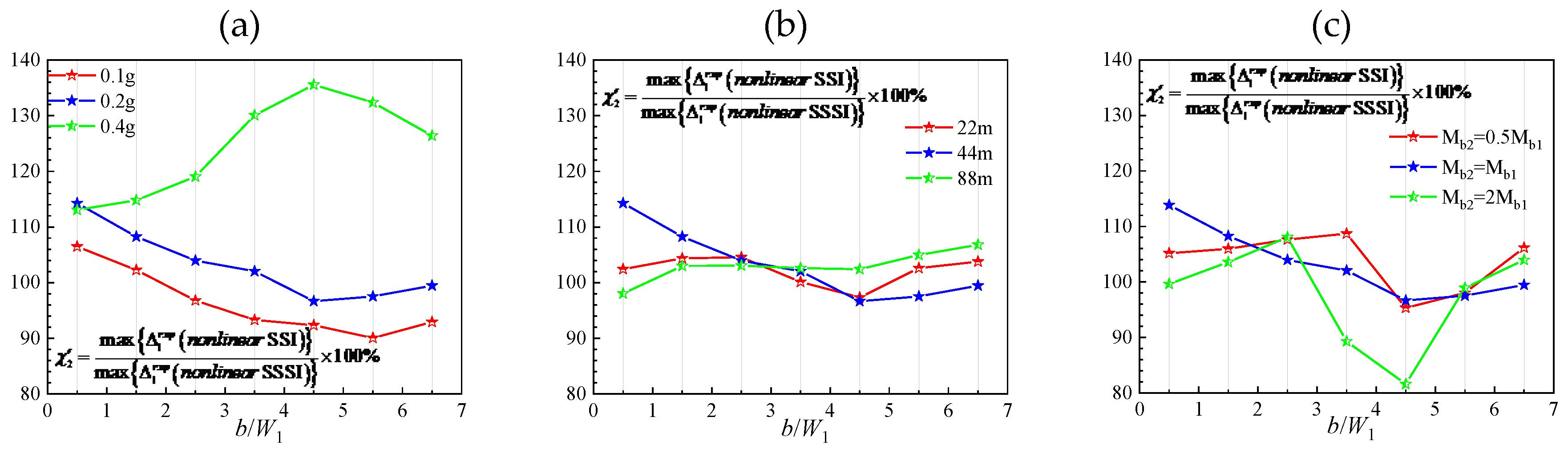
If the relative displacement due to foundation rotation is taken into account, the proportion of linear SSSI based on total relative displacement in the combined SSSI through nonlinear soil is shown in Figure 10. Unlike χ1, in most cases, the total relative displacement of nonlinear model is larger than that of linear model, especially for strong excitation (Ag=0.4g in our numerical cases). It indicates that the introduction of soil nonlinearity may amplify the total relative displacement significantly, in agreement with [3]. It’s noted that this amplification is entirely due to the amplification of foundation rotation in nonlinear model. To this end, it shows the ratios of foundation rotation in nonlinear model to that in linear model φN1/φL1, the proportion of building relative displacement due to foundation rotation in total relative displacement in linear model and that in nonlinear model are shown in Table 2. As shown, with the increase of incidence amplitudes, the foundation rotation increases rapidly. When the incidence amplitudes Ag=0.4g, φN1/φL1 is up to 10.215, and in this case the proportion of building relative displacement due to foundation rotation in total relative displacement in linear model and nonlinear model is 22.8% and 82.6%, respectively. This suggests that larger nonlinear strains may lead to larger foundation rotation, which may be much larger than that of corresponding linear case. In addition, adjacent structure’s flexibility, mass and separation distance have little effect on foundation rotation caused by soil nonlinearity, except for the case of closely spaced structures.
4.2.2. The Contribution of Soil-Structure Interaction (SSI) of a Single Structure and Across Interaction Between Structures Through Nonlinear Soil to the Combined SSSI Through Nonlinear Soil
The SSSI through the nonlinear soil can be decomposed into soil-structure interaction (SSI) of a single structure and across interaction between structures through nonlinear soil. To measure the proportion of SSI through nonlinear soil in the combined SSSI through nonlinear soil, it shows the ratio in Figure 11. As shown,is about 85%~105% except for the case of Ag=0.4g. It indicates that the contribution of SSI through nonlinear soil is much larger than that of across interaction between structures; for small and medium excitation (Ag=0.1g and 0.2g in our numerical cases), the building relative displacement amplitudes may be underestimated by about 15% if the across interaction is neglected. When the amplitude of excitation is large (Ag=0.4g), is about 110%~140%, which is much different from those of Ag=0.1g and Ag=0.2g. It suggests that large nonlinear strains and deformation in the soil caused by across interaction between structures can also contribute to the absorption of incidence energy.
Figure 11.
The contribution of SSI through nonlinear soil to the combined SSSI through nonlinear soil based on shearing relative displacement. In (a), the adjacent structure is identical with the Millikan Library Building, and the amplitude of excitation is Ag=0.1g, Ag=0.2g and Ag=0.4g, respectively. In (b), the height of the adjacent structure is H2=22m, 44m and 88m, respectively, and the corresponding fixed-base frequency is f12=4.66Hz, f12=2.33Hz, f12=1.16Hz, respectively. In (c), the mass of the adjacent structure is Mb2=0.5Mb1, Mb2=Mb1 and Mb2=2Mb1, respectively.
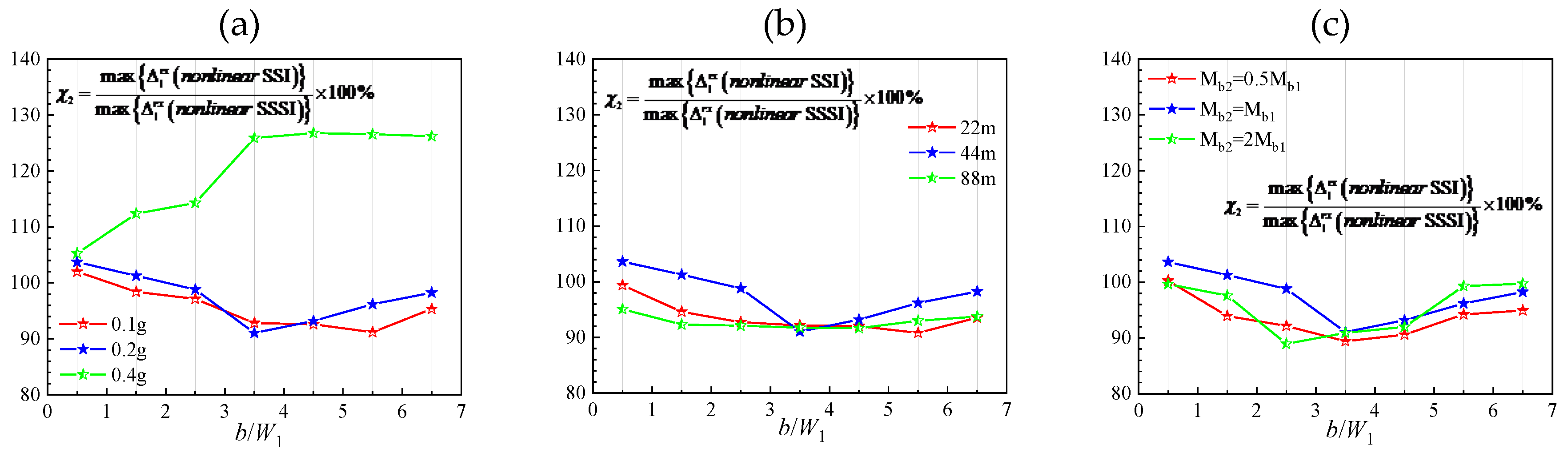
Figure 12.
The contribution of SSI through nonlinear soil to the combined SSSI through nonlinear soil based on total relative displacement. In (a), the adjacent structure is identical with the Millikan Library Building, and the amplitude of excitation is Ag=0.1g, Ag=0.2g and Ag=0.4g, respectively. In (b), the height of the adjacent structure is 22m, 44m and 88m, respectively, and the corresponding fixed-base frequency is f12=4.66Hz, f12=2.33Hz, f12=1.16Hz, respectively. In (c), the mass of the adjacent structure is Mb2=0.5Mb1, Mb2=Mb1 and Mb2=2Mb1, respectively.
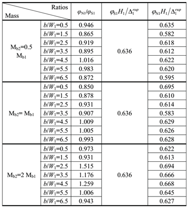
If building drift due to foundation rotation is taken into account, is shown in Fig.12. The ratios of foundation rotation in SSSI model to that in SSI model φN1/φS1, the proportion of building relative displacement due to foundation rotation in total relative displacement in SSI model and that in SSSI model are shown in Table 3. Unlike, the introduction of foundation rotation doesn’t change a lot except for the case Mb2=2Mb1. It suggests that across interaction through nonlinear soil doesn’t cause much foundation rotation except for the case of much heavier adjacent structure (Mb2=2Mb1). However, when the adjacent structure is much heavier (Mb2=2Mb1), the across interaction may enlarge foundation rotation and thus enlarge total relative displacement, e.g., when b/W1=2.5 the foundation rotation and total relative displacement in nonlinear SSSI model is 1.515 times and 1.230 times, respectively than that in nonlinear SSI model.
4. Conclusions
The dynamic SSSI through nonlinear soil is investigated by finite element-indirect boundary element (FE-IBE) coupled method. In the model, the soil in the far field is modeled by indirect boundary element method; and the soil in the near field is modeled by finite element method. The correctness and accuracy of the coupled method is verified by comparison with published results.
To study the effect of nonlinear zones in the soil, it’s assumed that only the soil can experience nonlinear deformations, while the structures will be forced to remain linear. The SSSI through nonlinear soil can be decomposed into linear SSSI and the contribution of soil linearity, or decomposed into SSI and across interaction through nonlinear soil. The proportions of linear SSSI, soil nonlinearity, SSI and across interaction through nonlinear soil in the combined SSSI effect are assessed. In addition, it’s analyzed whether the introduction of soil nonlinearity can reduce structural response by energy dissipation? The principal findings are as follows.
1. The introduction of soil nonlinearity can dissipate part of seismic energy and thus reduce the shearing relative displacement amplitudes significantly. However, it enlarges foundation rotation and thus may enlarge the total relative displacement significantly, as the part due to foundation rotation may account for greater proportion when the soil nonlinearity is taken into account, which should be paid attention especially for high-rise buildings.
2. Both linear SSSI and soil nonlinearity contribute significantly to the combined SSSI, and basically the proportion of linear SSSI is larger. If the adjacent structure is much heavier or the excitation is larger, the influence of soil linearity is larger.
3. The soil-structure interaction (SSI) of a single structure through nonlinear soil accounts for much larger proportion in the SSSI through nonlinear soil. In our numerical cases, the building relative displacement amplitudes may be underestimated by less than 15% if the across interaction is neglected for small and medium excitation. However, for intense excitation, the across interaction can’t be neglected.
4. If the adjacent structure is much heavier, the across interaction through nonlinear soil may enlarge foundation rotation and thus enlarge total relative displacement evidently.
In conclusion, the SSSI through nonlinear soil may be significantly different from linear SSSI or SSI through nonlinear soil. Compared with linear SSSI, the shearing relative displacement amplitudes may be reduced evidently by soil nonllinearity, while the foundation rotation may be enlarged significantly. Compared with nonlinear SSI, the across interaction through nonlinear soil may enlarge foundation rotation evidently if the adjacent structure is much heavier.
Funding
The research described in this paper was financially supported by Tianjin Municipal Science and Technology Bureau (Grant Nos. 23JCYBJC00390, 23YDTPJC00670).
References
- Han, B.; Chen, S.; Liang, J. 2D dynamic structure-soil-structure interaction: A case study of Millikan Library Building. Eng. Anal. Bound. Elements 2020, 113, 346–358. [Google Scholar] [CrossRef]
- Gičev, V.; Trifunac, M.D. Energy dissipation by nonlinear soil strains during soil–structure interaction excited by SH pulse. Soil Dyn. Earthq. Eng. 2012, 43, 261–270. [Google Scholar] [CrossRef]
- Vicencio, F.; Alexander, N.A. Dynamic interaction between adjacent buildings through nonlinear soil during earthquakes. Soil Dyn. Earthq. Eng. 2018, 108, 130–141. [Google Scholar] [CrossRef]
- Nateghi-A, F.; Rezaei-Tabrizi, A. Nonlinear dynamic response of tall buildings considering structure–soil–structure effects. Struct. Des. Tall Spéc. Build. 2011, 22, 1075–1082. [Google Scholar] [CrossRef]
- Bybordiani, M.; Arici, Y. Structure-soil-structure interaction of adjacent buildings subjected to seismic loading. Earthq. Eng. Struct. Dyn. 2019, 48, 731–748. [Google Scholar] [CrossRef]
- Alexander, N.; Ibraim, E.; Aldaikh, H. A simple discrete model for interaction of adjacent buildings during earthquakes. Comput. Struct. 2013, 124, 1–10. [Google Scholar] [CrossRef]
- Vicencio, F.; Alexander, N.A. Dynamic Structure-Soil-Structure Interaction in unsymmetrical plan buildings due to seismic excitation. Soil Dyn. Earthq. Eng. 2019, 127. [Google Scholar] [CrossRef]
- Liu, S.; Li, P.; Zhang, W.; Lu, Z. Experimental study and numerical simulation on dynamic soil-structure interaction under earthquake excitations. Soil Dyn. Earthq. Eng. 2020, 138. [Google Scholar] [CrossRef]
- He Y, Xia D, Yan Y, et al. Dynamic behaviors of SSDI system based on nonlinearity of soil in site. Chinese Journal of Geotechnical Engineering, 2009, 31(4):521-527.
- Trombetta NW, Mason HB, Hutchinson TC, Zupan JD, Bray JD, Kutter BL, Nonlinear soil-foundation-structure and structure-soil-structure interaction: centrifuge test observations, Journal of Geotechnical and Geoenvironmental Engineering, ASCE 2013, 04013057.
- Mason, H.; Trombetta, N.; Chen, Z.; Bray, J.; Hutchinson, T.; Kutter, B. Seismic soil–foundation–structure interaction observed in geotechnical centrifuge experiments. Soil Dyn. Earthq. Eng. 2013, 48, 162–174. [Google Scholar] [CrossRef]
- Trombetta, N.; Mason, H.; Chen, Z.; Hutchinson, T.; Bray, J.; Kutter, B. Nonlinear dynamic foundation and frame structure response observed in geotechnical centrifuge experiments. Soil Dyn. Earthq. Eng. 2013, 50, 117–133. [Google Scholar] [CrossRef]
- Luco JE, Contesse L. Dynamic structure-soil-structure interaction. Bulletin of the Seismological Society of America 1973; 63(4): 1289-1303.
- Wong HL, Trifunac MD. Two-dimensional, antiplane, building-soil-building interaction for two or more buildings and for incident planet SH waves. Bulletin of the Seismological Society of America 1975; 65(6): 1863-1885.
- Wong, H.L. Dynamic Soil-Structure Interaction, Report EERL-75-01, Earthquake Engineering Research Lab, California Institute of Technology, Pasadena, California, 1975.
- Murakami, H.; Luco, J.E. Seismic Response of a Periodic Array of Structures. J. Eng. Mech. Div. 1977, 103, 965–977. [Google Scholar] [CrossRef]
- Guéguen, P.; Colombi, A. Experimental and Numerical Evidence of the Clustering Effect of Structures on Their Response during an Earthquake: A Case Study of Three Identical Towers in the City of Grenoble, France. Bull. Seism. Soc. Am. 2016, 106, 2855–2864. [Google Scholar] [CrossRef]
- Wang, S.; Schmid, G. Dynamic structure-soil-structure interaction by FEM and BEM. Comput. Mech. 1992, 9, 347–357. [Google Scholar] [CrossRef]
- Padrón, L.; Aznárez, J.; Maeso, O. Dynamic structure–soil–structure interaction between nearby piled buildings under seismic excitation by BEM–FEM model. Soil Dyn. Earthq. Eng. 2009, 29, 1084–1096. [Google Scholar] [CrossRef]
- Bybordiani, M.; Arici, Y. Structure-soil-structure interaction of adjacent buildings subjected to seismic loading. Earthq. Eng. Struct. Dyn. 2019, 48, 731–748. [Google Scholar] [CrossRef]
- Gueguen P, Bard PY, Chávez FJ. Site-City Seismic Interaction in Mexico City-Like Environments: An Analytical Study. Bulletin of the Seismological Society of America, 2002, 92(2):794-811.
- Gičev, V.; Trifunac, M.D. Energy dissipation by nonlinear soil strains during soil–structure interaction excited by SH pulse. Soil Dyn. Earthq. Eng. 2012, 43, 261–270. [Google Scholar] [CrossRef]
- Bolisetti, C.; Whittaker, A.S.; Coleman, J.L. Linear and nonlinear soil-structure interaction analysis of buildings and safety-related nuclear structures. Soil Dyn. Earthq. Eng. 2018, 107, 218–233. [Google Scholar] [CrossRef]
- Raychowdhury, P. Seismic response of low-rise steel moment-resisting frame (SMRF) buildings incorporating nonlinear soil–structure interaction (SSI). Eng. Struct. 2011, 33, 958–967. [Google Scholar] [CrossRef]
- von Estorff, O.; Firuziaan, M. Coupled BEM/FEM approach for nonlinear soil/structure interaction. Eng. Anal. Bound. Elements 2000, 24, 715–725. [Google Scholar] [CrossRef]
- Liang, J.; Han, B.; Todorovska, M.I.; Trifunac, M.D. 2D dynamic structure-soil-structure interaction for twin buildings in layered half-space II: Incident SV-waves. Soil Dyn. Earthq. Eng. 2018, 113, 356–390. [Google Scholar] [CrossRef]
- Yuan X, Sun R, Sun J, Meng S, Shi Z. Laboratory experimental study on dynamic shear modulus ratio and damping ratio of soils. Earthquake Engineering and Engineering Vibration, 2000; 20(4):133-139.
- Luco JE, Wong HL, Trifunac MD. Soil-structure interaction effects on forced vibration tests. Report 86-05, Department of Civil Engineering, University of Southern California, Los Angeles.
Figure 1.
The model.
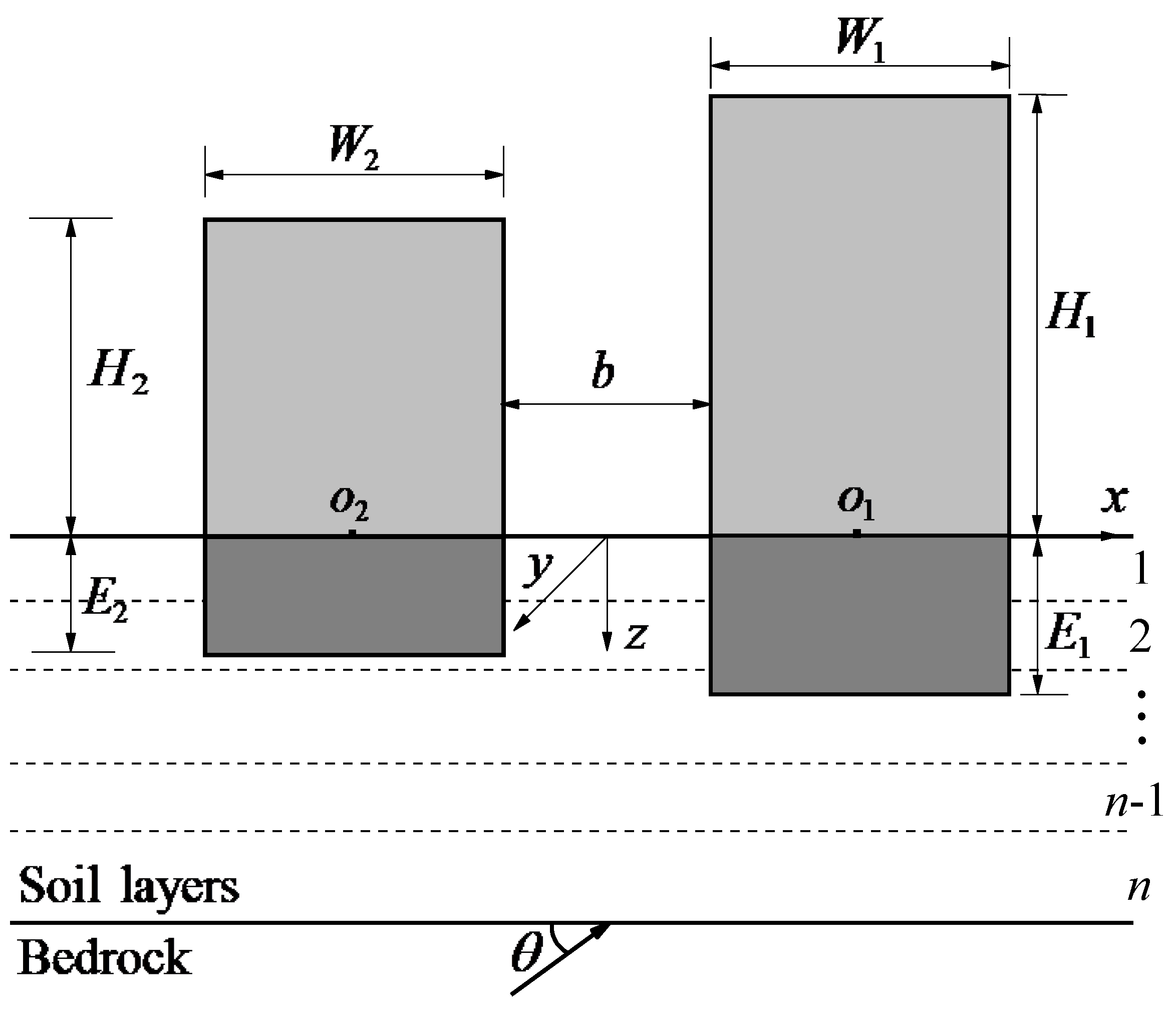
Figure 2.
The model of FE and IBE subdomain.
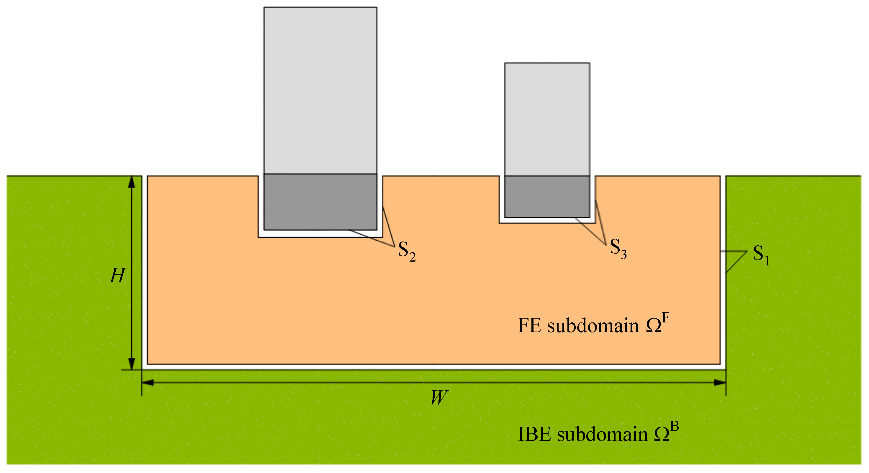
Figure 3.
Comparison of our results for twin buildings supported by semi-circular rigid foundations with those obtained by indirect boundary element method in [27]. (a). Foundation displacement and building relative displacement for βR/βL=2, D/W1=2 (D/a=4), ζR=ζL=3.5%, νR=νL=1/3, W1=W2=2a, H1=H2=2W1=4a, ε=4, Mb/M0=5 and M0/Ms=0.2. (b). Same as (a) but for βR/βL=5.
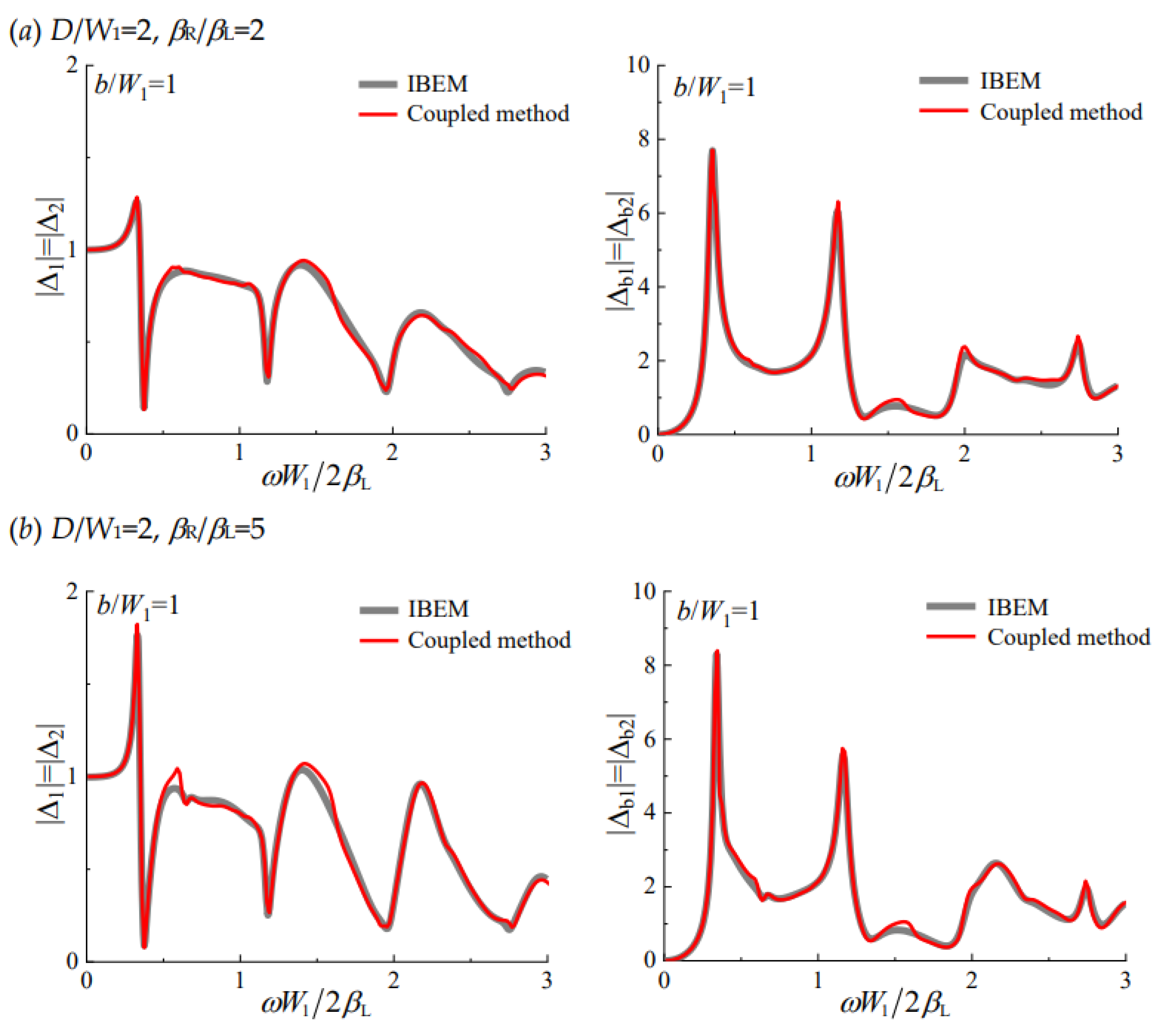
Figure 4.
Deformed configuration in x-direction of the structure (i=1,2).
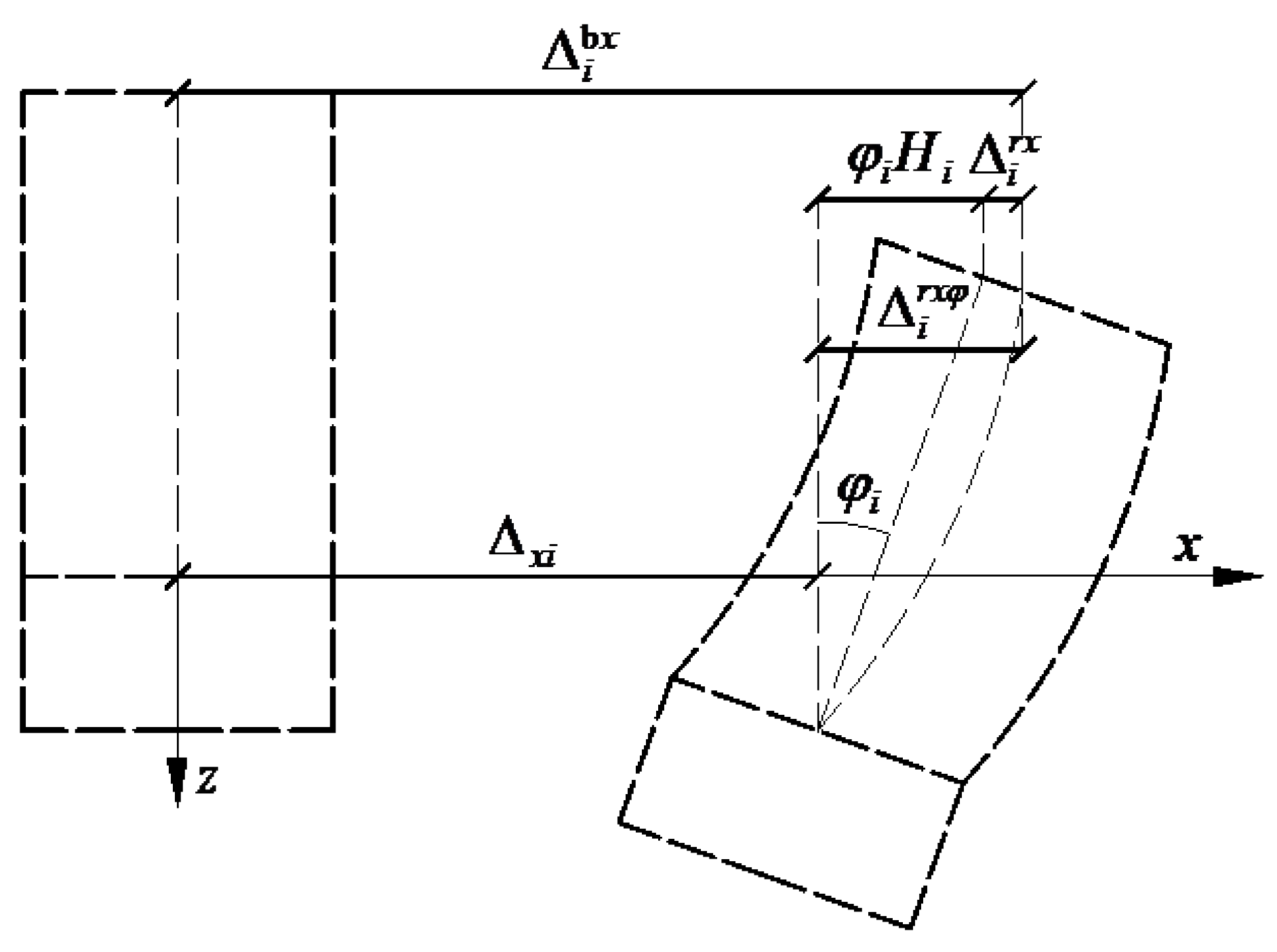
Figure 5.
Shear modulus μ and damping ratio ζ versus soil shear strain γ [29].
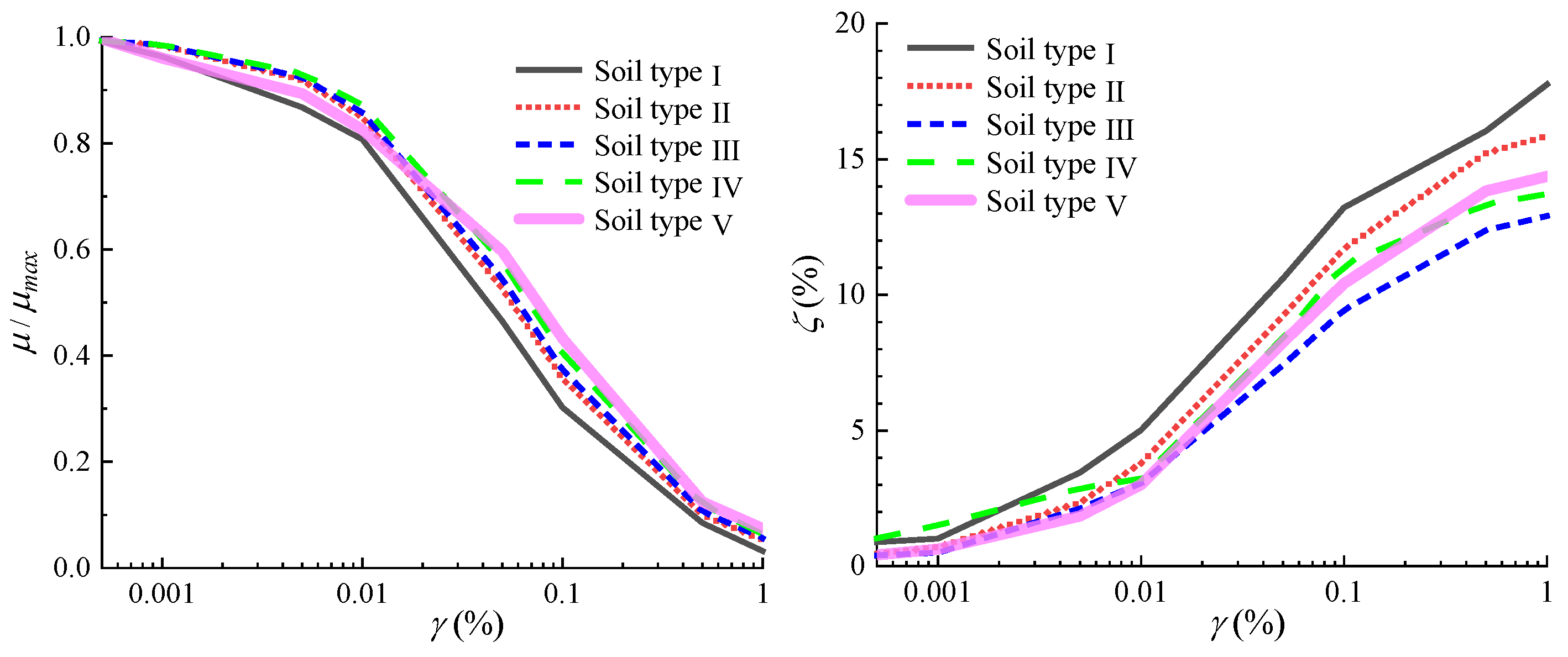
Figure 6.
The time history and Fourier spectrum of incident earthquake waves.
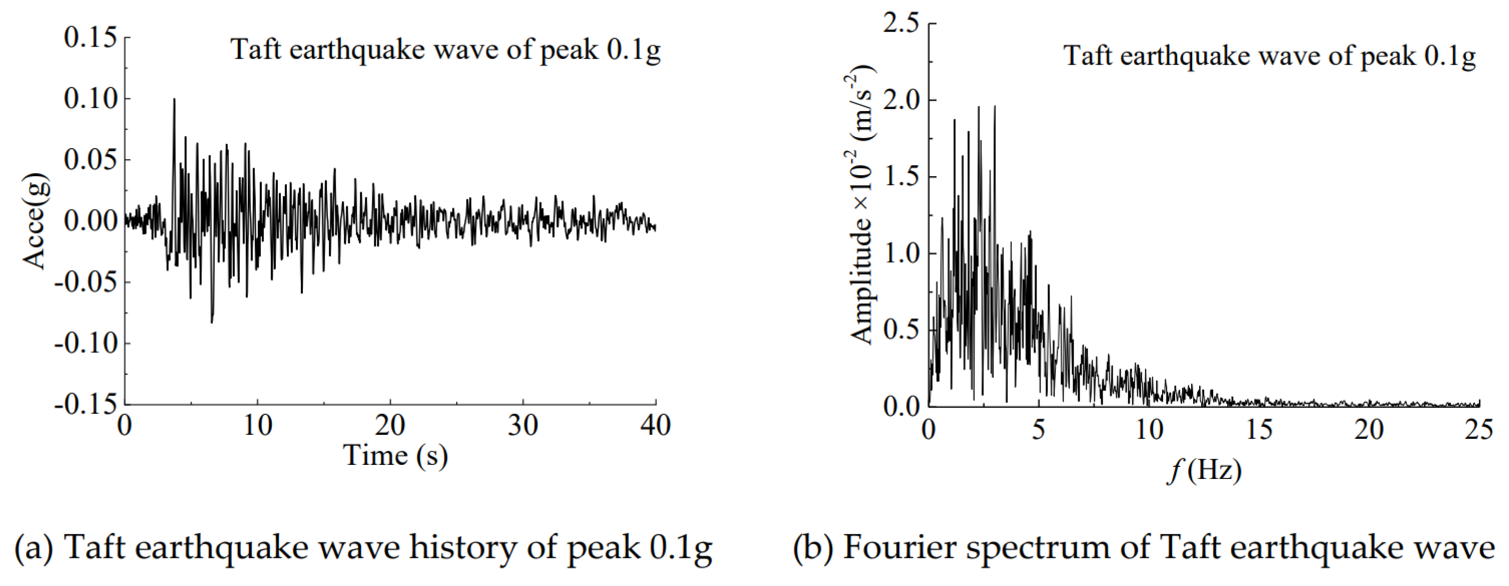
Figure 7.
Building relative displacement for nonlinear SSI model compared with those for fixed-base model.
Figure 7.
Building relative displacement for nonlinear SSI model compared with those for fixed-base model.
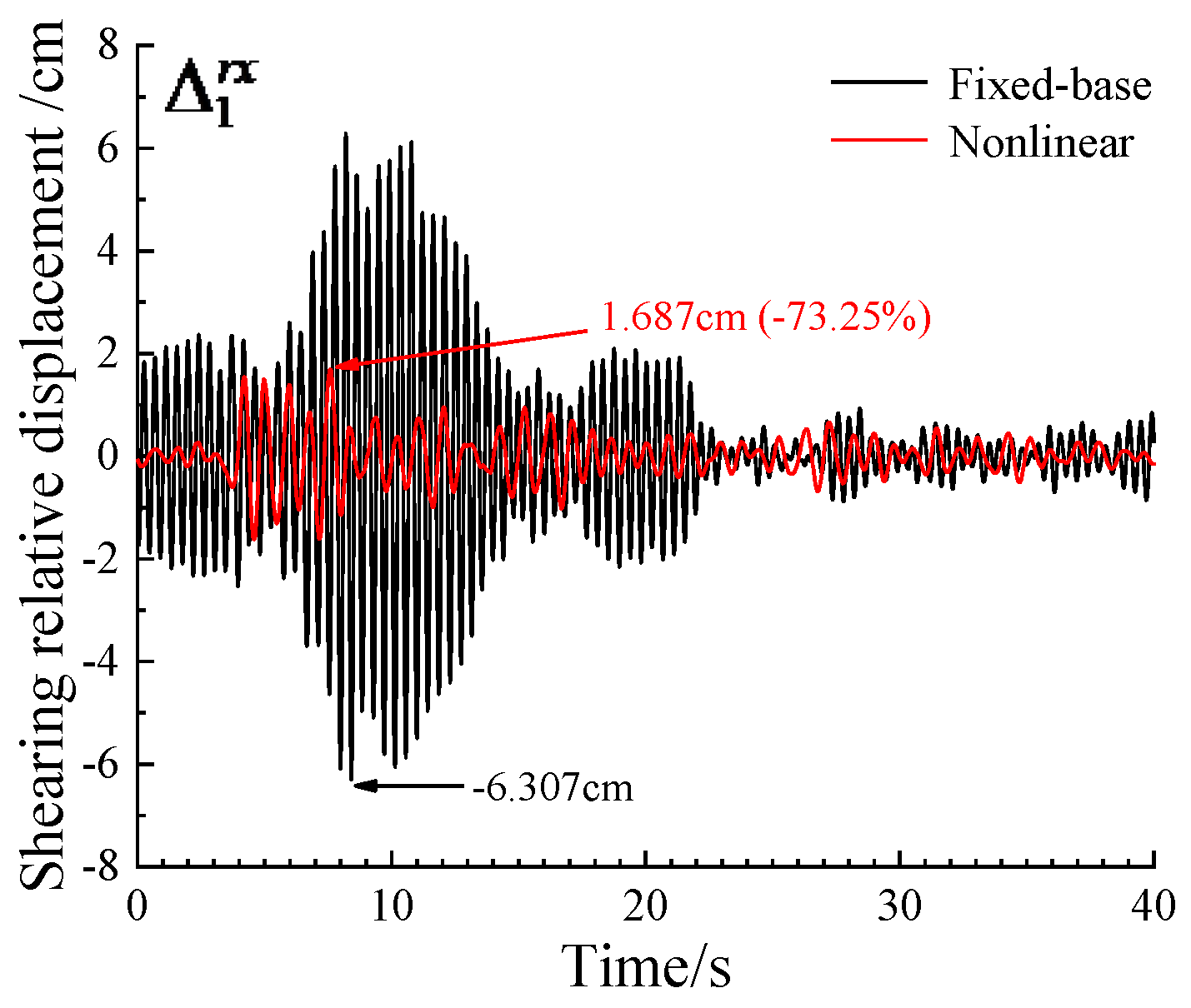
Figure 8.
Building relative displacement for nonlinear SSI model compared with those for linear SSI model.
Figure 8.
Building relative displacement for nonlinear SSI model compared with those for linear SSI model.
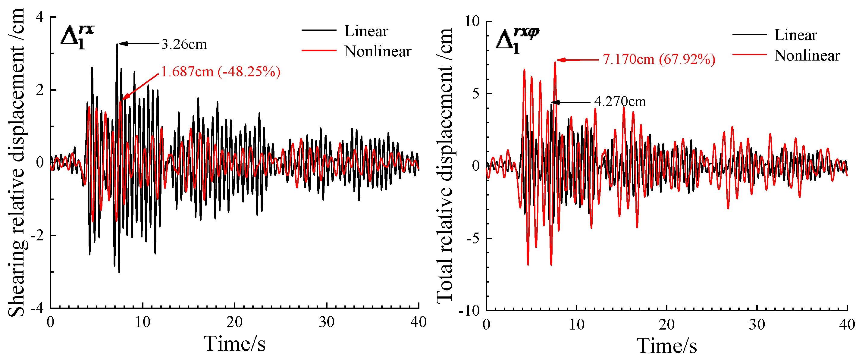
Figure 9.
The contribution of linear SSSI to the combined SSSI through nonlinear soil based on shearing relative displacement. In (a), the adjacent structure is identical with the Millikan Library Building, and the amplitude of excitation is Ag=0.1g, 0.2g and 0.4g, respectively. In (b), the height of the adjacent structure is H2=22m, 44m and 88m, respectively, and the corresponding fixed-base frequency is f12=4.66Hz, f12=2.33Hz, f12=1.16Hz, respectively. In (c), the mass of the adjacent structure is Mb2=0.5Mb1, Mb2=Mb1 and Mb2=2Mb1, respectively.
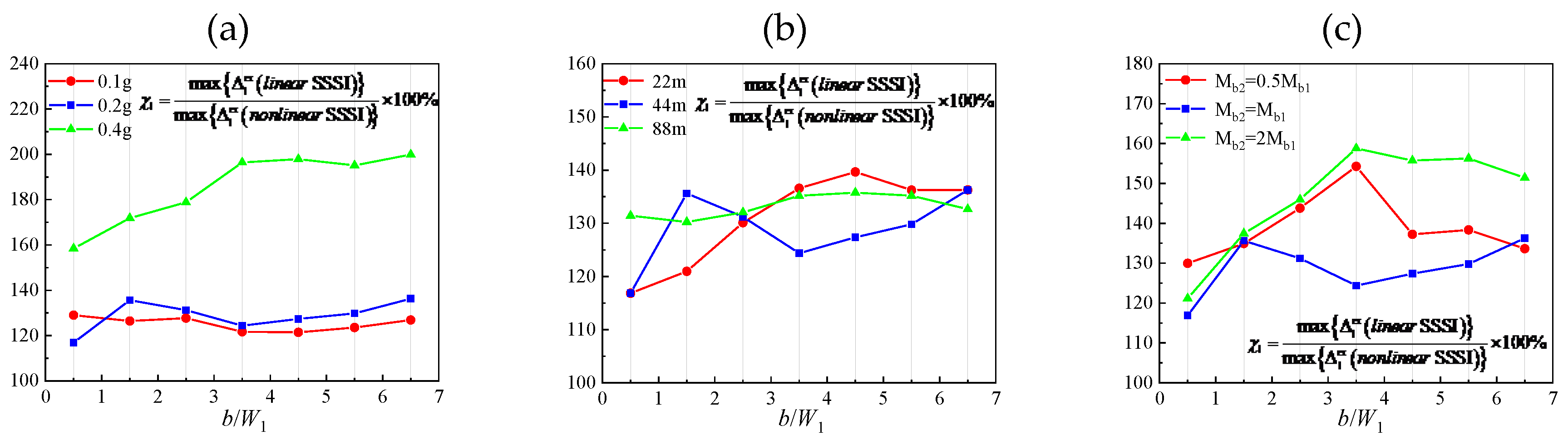
Figure 10.
The contribution of linear SSSI to the combined SSSI through nonlinear soil based on total relative displacement. In (a), the adjacent structure is identical with the Millikan Library Building, and the amplitude of excitation is Ag=0.1g, Ag=0.2g and Ag=0.4g, respectively. In (b), the height of the adjacent structure is 22m, 44m and 88m, respectively, and the corresponding fixed-base frequency is f12=4.66Hz, f12=2.33Hz, f12=1.16Hz, respectively. In (c), the mass of the adjacent structure is Mb2=0.5Mb1, Mb2=Mb1 and Mb2=2Mb1, respectively.
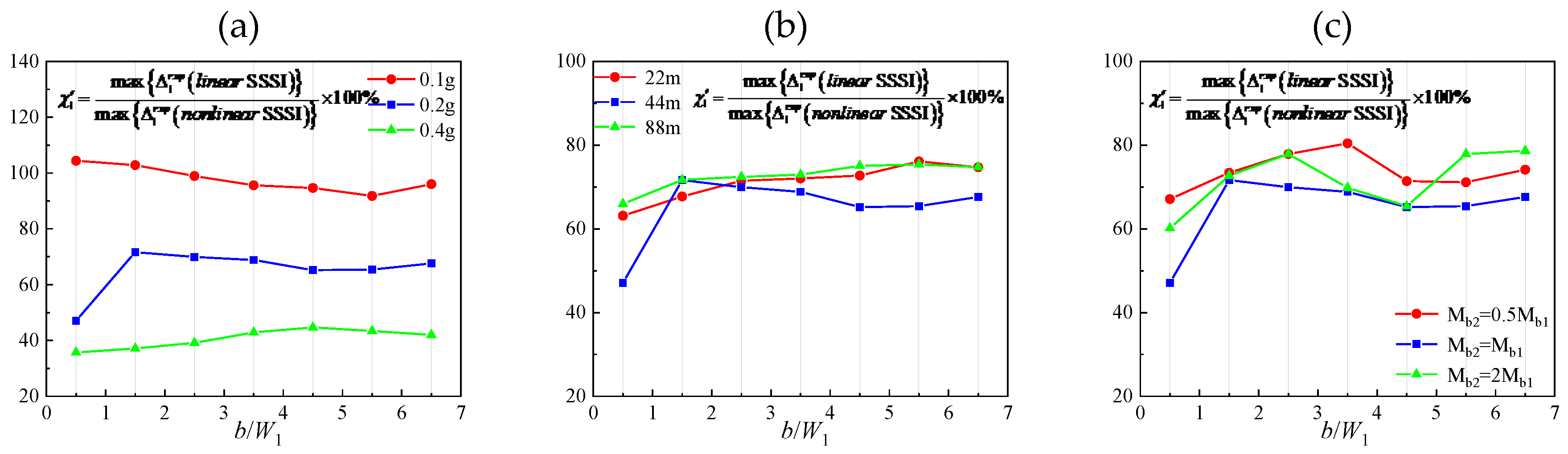

Table 1.
Soil parameters of the site of Millikan Library Building [30].
| Soil layer No. |
S-wave velocity (βi, i=1~10) (m/s) |
Layer thickness (di, i=1~10) (m) |
Depth range (m) |
Mass density (ρi, i=1~10) (kg/m3) |
| 1(Ⅰ) | 298.7 | 1.83 | 0-1.83 | 1810 |
| 2(Ⅰ) | 298.7 | 0.91 | 1.83-2.74 | 1810 |
| 3(Ⅰ) | 298.7 | 2.75 | 2.74-5.49 | 1810 |
| 4(Ⅱ) | 387.1 | 1.52 | 5.49-7.01 | 1810 |
| 5(Ⅱ) | 387.1 | 2.74 | 7.01-9.75 | 1810 |
| 6(Ⅲ) | 454.2 | 3.66 | 9.75-13.41 | 1810 |
| 7(Ⅳ) | 487.7 | 6.71 | 13.41-20.12 | 1810 |
| 8(Ⅴ) | 609.6 | 82.29 | 20.12-102.41 | 1810 |
| 9(Ⅴ) | 762.0 | 16.16 | 102.41-118.57 | 1810 |
| Bedrock | 944.8 | - | 118.57- | 1810 |
Table 2.
The ratios of foundation rotation in nonlinear model to that in linear model and the proportion of building relative displacement due to foundation rotation in total relative displacement.
Table 2.
The ratios of foundation rotation in nonlinear model to that in linear model and the proportion of building relative displacement due to foundation rotation in total relative displacement.
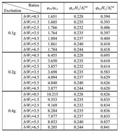
Table 3.
The ratios of foundation rotation in SSSI model to that in SSI model and the proportion of building relative displacement due to foundation rotation in total relative displacement.
Table 3.
The ratios of foundation rotation in SSSI model to that in SSI model and the proportion of building relative displacement due to foundation rotation in total relative displacement.
Disclaimer/Publisher’s Note: The statements, opinions and data contained in all publications are solely those of the individual author(s) and contributor(s) and not of MDPI and/or the editor(s). MDPI and/or the editor(s) disclaim responsibility for any injury to people or property resulting from any ideas, methods, instructions or products referred to in the content. |
© 2025 by the authors. Licensee MDPI, Basel, Switzerland. This article is an open access article distributed under the terms and conditions of the Creative Commons Attribution (CC BY) license (http://creativecommons.org/licenses/by/4.0/).
Copyright: This open access article is published under a Creative Commons CC BY 4.0 license, which permit the free download, distribution, and reuse, provided that the author and preprint are cited in any reuse.


