
Submitted:
11 August 2025
Posted:
13 August 2025
You are already at the latest version
Abstract
The research presents the thermal performance comparison of silicone and non-silicone thermal pads using a newly designed steady-state thermal interface material (TIM) testing apparatus. The TIM tester follows the ASTM D5470-12 standard guidelines for testing thermal properties. TIMs are applied between two solid surfaces to improve heat transfer by eliminating air gaps that naturally occur due to surface roughness and non-flatness. Since TIMs possess significantly higher thermal conductivity than air, they effectively reduce contact resistance at the interface, thereby minimizing the risk of overheating in electronic systems. In this work, the thermal resistances of silicone and non-silicone thermal pads were compared over a pressure range of 10–50 psi. Results indicate that non-silicone pads consistently exhibit lower thermal resistance than their silicone counterparts under identical testing conditions.
Keywords:
Thermal interface material
; thermal resistance
; thermal pad
; heat transfer
1. Introduction
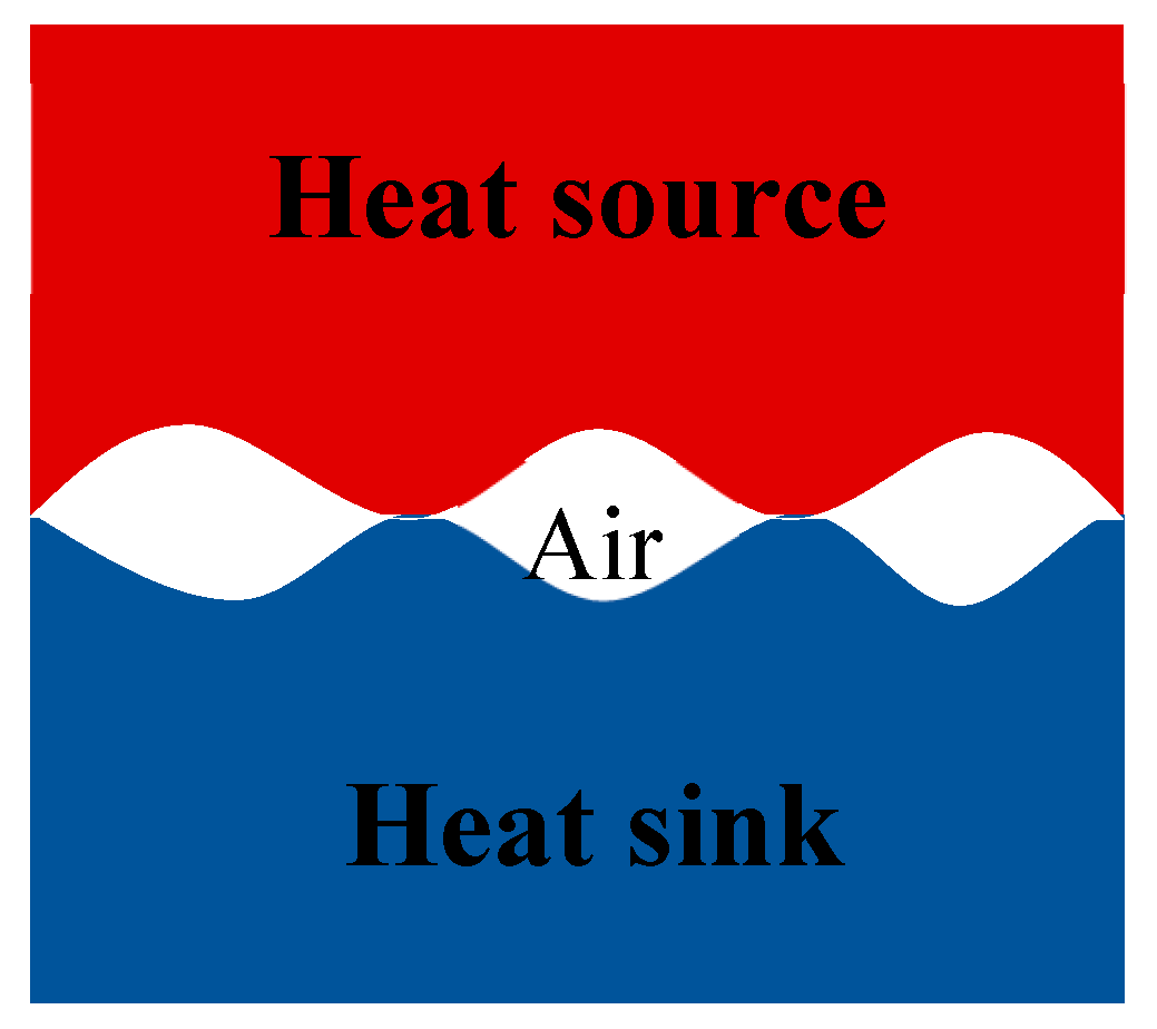
As computers and electronic devices continue to become smaller, faster, and more powerful, efficient thermal management has emerged as one of the most pressing challenges in modern electronics. Increasing power densities result in greater heat generation, which must be dissipated effectively to ensure device reliability and prevent thermal failure. Heat sinks, with their extended finned geometries, are widely employed to enhance cooling; however, before heat can be transferred to the surrounding environment, it must first be conducted from the heat-generating component to the heat sink. Where the heat source meets the heat sink, there are minuscule air-filled gaps due to the roughness of these surfaces at the microscopic level [1,2,3], as shown in Figure 1. Due to the low thermal conductivity of air (0.026 W/m.K) [3], these gaps reduce the amount of heat transfer from the source to the sink, resulting in additional resistance to heat flow, known as thermal contact resistance [1,2,3].
Figure 1.
A magnified contact between the heat source and heat sink with air at the interface.
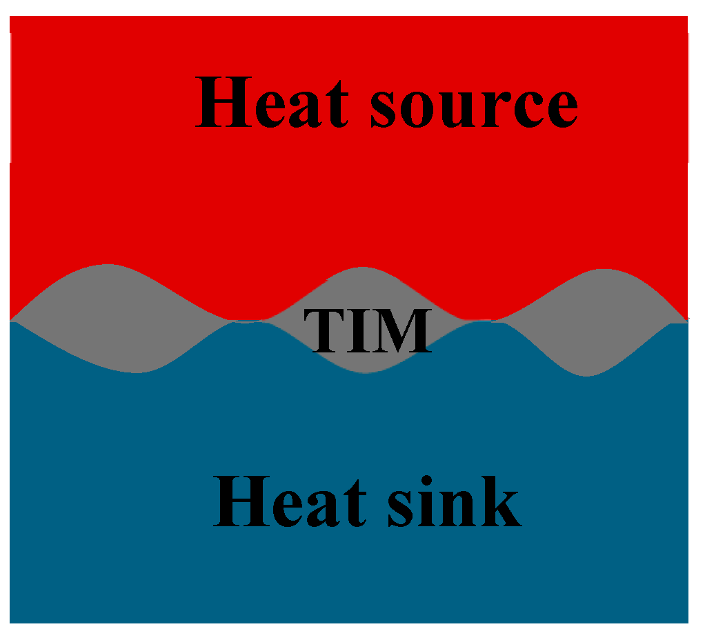
One way to reduce the thermal contact resistance is by filling the gap with a highly conductive material, known as a thermal interface material (TIM) [1,2,3,4]. The TIM increases the number of contact points between the two surfaces, allowing more heat to be conducted across the interface [5]. When a TIM is added, there is still a contact resistance between the surface and the TIM due to the microscopic roughness of the surface; however, the overall thermal interface resistance is reduced significantly. A magnified view of an imperfect contact with TIM is shown in Figure 2.
Figure 2.
A magnified contact between the heat source and heat sink with TIM at the interface.
There are many different types of TIMs, including thermal pads, thermal grease, phase change materials, liquid metal alloys, and carbon nanotubes [3,4,5,6,7,8,9,10]. Each type of TIM has different properties with different advantages and disadvantages. This study focuses on the application of thermal pads as TIM.
Thermal gap pads are a class of TIMs designed to fill air gaps and ensure effective heat transfer between electronic components and heat spreaders or heat sinks. Thermal gap pads are typically made from silicone or non-silicone polymer matrices embedded with thermally conductive fillers such as ceramic particles or graphite. Their soft, compliant nature allows them to fill uneven surfaces and air gaps, thereby minimizing interfacial thermal resistance [11]. Unlike thermal greases, which can suffer from issues like pump-out and drying over time, thermal gap pads offer long-term mechanical stability and are easier to handle and rework during assembly processes [12].
Silicone-based thermal gap pads are the most widely used due to their high flexibility, thermal stability, and ability to conform to surface irregularities [4]. These pads typically consist of a silicone elastomer matrix embedded with thermally conductive fillers such as alumina, boron nitride, or graphite [13]. Their inherent softness allows them to compress easily, minimizing interfacial resistance and enhancing heat dissipation. Moreover, silicone pads offer long-term reliability, maintaining performance over extended thermal cycling [12]. However, silicone migration (also known as outgassing or “bleed-out”) can be a concern, particularly in optoelectronic or disk-drive applications where contamination sensitivity is critical [14].
Non-silicone thermal gap pads have been developed to address contamination associated with silicone materials. These pads are often formulated from hydrocarbon-, urethane-, or acrylic-based polymers loaded with thermally conductive fillers [11]. Non-silicone pads provide similar levels of conformability and thermal conductivity but avoid issues related to volatile siloxane outgassing [15]. As a result, they are especially suitable for applications in telecommunications, automotive electronics, and optical devices, where silicone contamination could compromise performance.
2. Materials and Methods
The Materials chosen for this research were silicone and non-silicone thermal pads of the same nominal thickness (1 mm) and the thermal conductivity, 11 W/m.K. The goal was to compare the thermal resistances at different pressures.
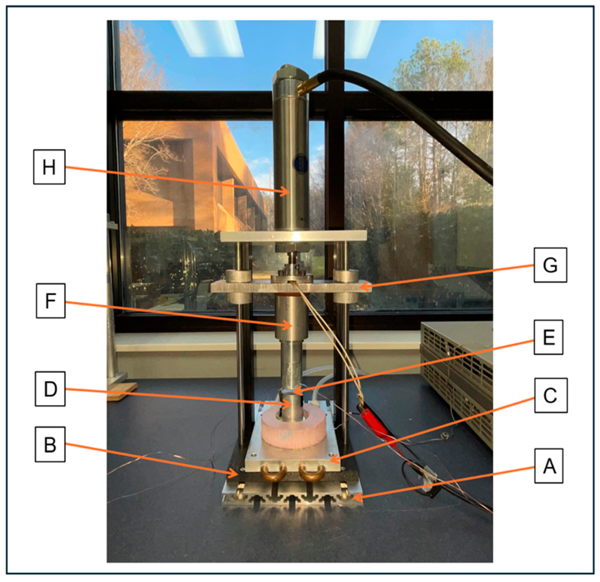
To evaluate the thermal performance of TIMs, a steady-state thermal setup has been used widely [3,4,5,16]. For this research purpose, a steady-state thermal test setup was designed and built as shown in Figure 3. The design followed the guidelines outlined in ASTM D5470 standard [17]. The test apparatus consists of two vertically aligned meter bars made of aluminum 6061 T6 alloy. The top meter bar was hot, and the bottom one functioned as cold. One-dimensional heat flow through the meter bar was maintained by minimizing lateral losses using proper insulation. The thermal resistance of the TIM was calculated based on fundamental heat transfer principles by measuring the temperature gradients along the meter bars and the applied heat flow.
The top meter bar contained three thermocouple holes, while the bottom bar included two for precise temperature measurement at the interface. A cartridge heating element was embedded in the top meter bar. The heater was powered by a DC power supply. The bottom meter bar is mounted on a cooling plate, which is connected to a recirculating chiller. Water flows through two inlet and outlet pipes to maintain an isothermal boundary condition.
Structural support was provided by two vertical cylindrical columns on either side of the setup. A rectangular aluminum plate was placed on top of the heater and bolted to these columns. Compressive force was applied using a pneumatic air cylinder mounted above this plate, delivering adjustable pressure up to 100 psi via a regulated air hose and pressure gauge. To stabilize the assembly, a second aluminum plate was bolted to the top of the columns. After applying the desired pressure, appropriate insulation was wrapped around the meter bars to ensure accurate and consistent heat flow measurements.
Figure 3.
The experimental setup without insulation wrapped around the meter bar A. Aluminum base plate B. 3-D printed plate C. Aluminum cold plate D. Bottom half of meter bar E. TIM insertion space F. Top half of meter bar G. Vertically sliding plate H. Compressed air cylinder.
Figure 3.
The experimental setup without insulation wrapped around the meter bar A. Aluminum base plate B. 3-D printed plate C. Aluminum cold plate D. Bottom half of meter bar E. TIM insertion space F. Top half of meter bar G. Vertically sliding plate H. Compressed air cylinder.
The TIM was placed between the two meter bars, after which the top meter bar was carefully lowered onto the bottom bar. Any excess TIM was removed to ensure clean contact surfaces. Once aligned, the desired pressure was applied, and insulation was wrapped around the meter bars to minimize heat loss. Electrical power was then supplied to the heater embedded in the top meter bar, initiating heat flow through the TIM. Heat was conducted in a one-dimensional path toward the bottom meter bar, which was maintained at a constant temperature by the cooling plate. Data collection began once thermal steady-state condition was achieved as described by the standard [17].
3. Results and Discussion
The tests were performed without any sample (called baseline tests) and using two types of thermal pads: silicone thermal pad and non-silicone thermal pad.
3.1. Baseline Tests
The purpose of these to tests was to measure the thermal resistance without any TIM at the interface. If there is no TIM placed at the interface, most of the interfacial spaces are filled with air, which is a poor conductor of heat. The thermal resistance was expected to be high without any TIM at the interface. Tests were conducted at two different pressures, 20 and 50 psi, and the results are presented in Table 1. Results showed that with the increase of pressure, the thermal resistance decreased. This is because, with pressure, the meter bar surfaces make better contact, and more air is displaced from the interface. These baseline tests with high thermal resistances justify the importance of using a TIM at the interface to enhance heat transfer.

Table 1.
Thermal resistance of bare interface (without any TIM) at different applied pressures.
| Pressure (psi) | Thermal Resistance (K/W) |
|---|---|
| 20 | 0.64 |
| 50 | 0.53 |
3.2. Testing of Silicone Thermal Pad
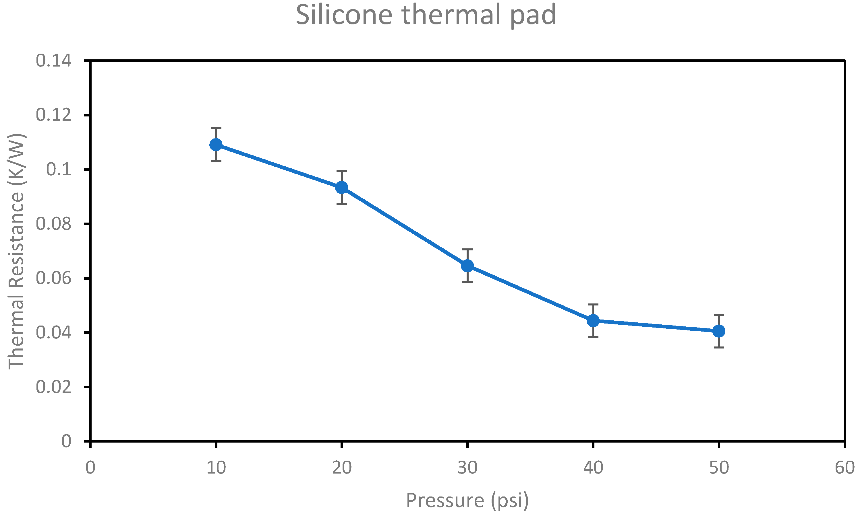
A silicone thermal pad of thermal conductivity 11 W/m.K was chosen for the test. The tests were performed at different pressures ranging from 10 to 50 psi. Figure 4 represents the thermal resistance at various applied pressures. The pad offers lower thermal resistance (better heat transfer) when compared to tests without any TIM. At the same pressure 20 psi, the thermal resistance of silicone pad is about 85% lower than baseline test. This result emphasizes the importance of using TIM at the interface. With the silicone pad, the thermal resistance decreased by about 63% as the pressure increases from 10 to 50 psi. As the pressure increases, the TIM materials make better contact with the matting surfaces by displacing more air gaps from the interface, thereby reducing the contact resistance. Also, these are soft elastomeric pads, which deforms under pressure. With increasing pressure, the thickness decreases, which in turn reduces the conduction resistance. Combining these two effects, the overall thermal resistance decreases with increasing pressure.
Figure 4.
Thermal resistance of Silicone thermal pad at various pressures.
3.3. Testing of Non-silicone Thermal Pad
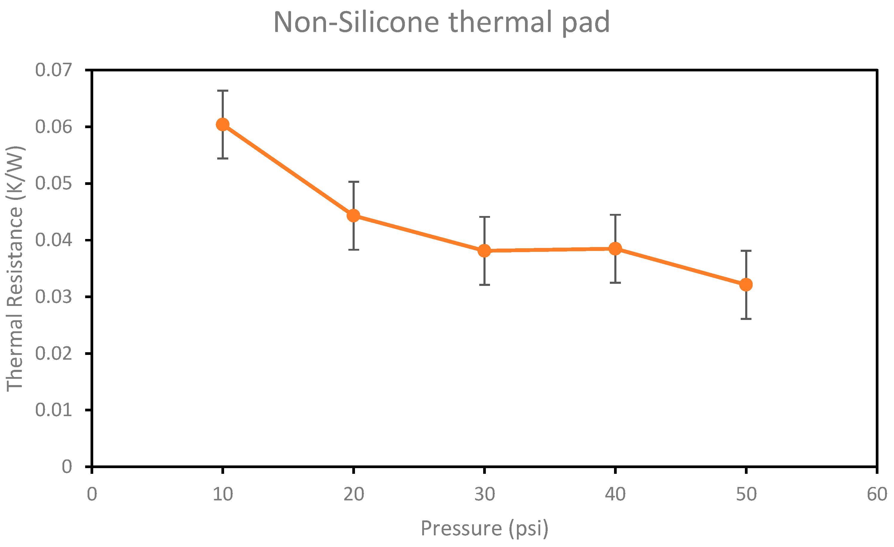
A non-silicone thermal pad of the same thermal conductivity as the silicone thermal pad (11 W/m.K) was chosen for the test. Again, similar to the silicone pad, the tests were performed at various pressures, and the thermal resistance values are shown in Figure 5. Similar trend was observed: thermal resistances decreased by about 47% with the increase of pressure from 10 to 50 psi. This behavior was expected and, for the same reason, is explained in the previous section.
Figure 5.
Thermal resistance of non-Silicone thermal pad at various pressures.
3.4. Performance Comparison
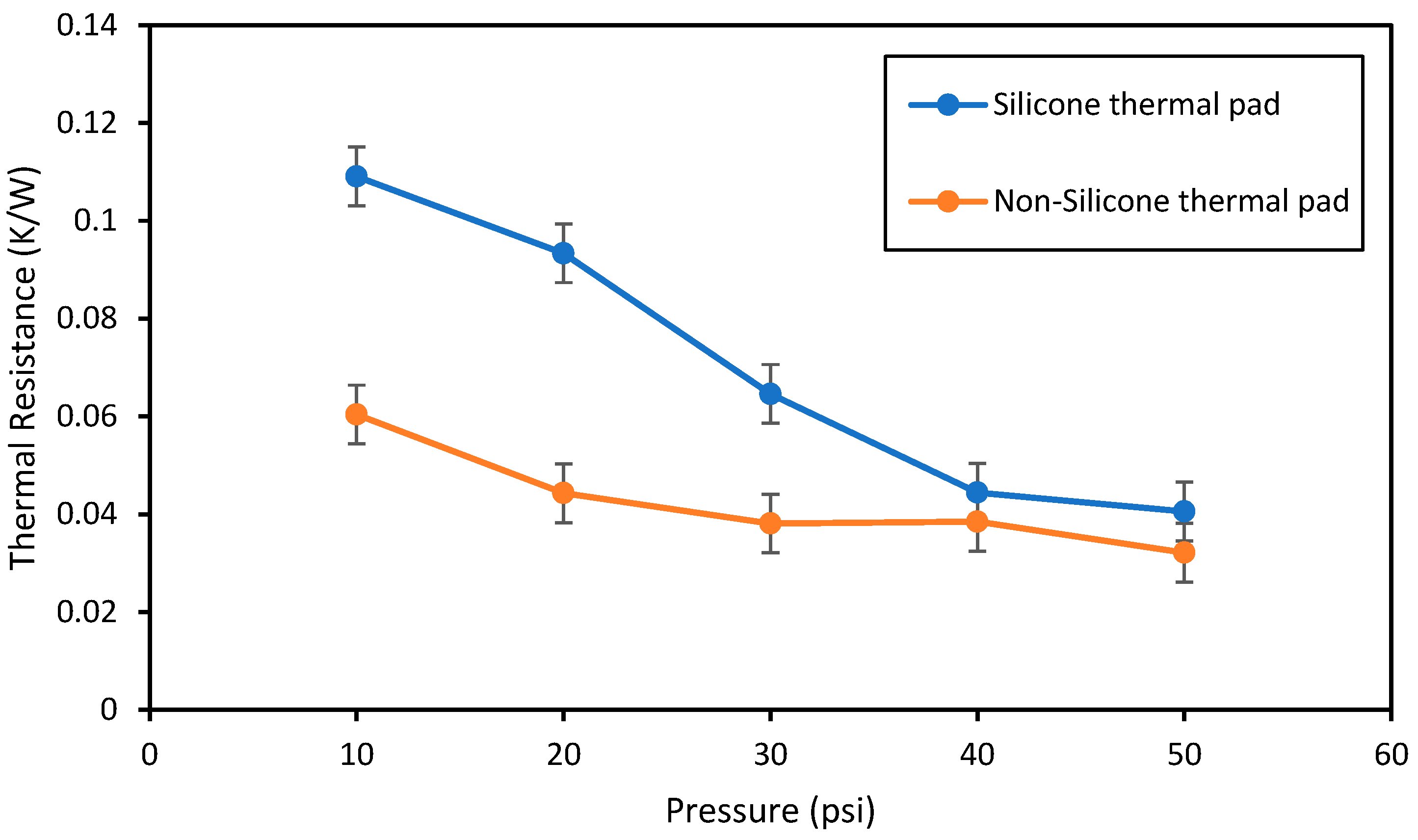
Figure 6 shows the performance comparison of the thermal resistance of silicone and non-silicone thermal pads. Even though both of them have the same conductivity and the same initial thickness, the thermal resistance differs. At all pressures in the range 10-50 psi, the non-silicone pad offers better thermal performance (lower thermal resistances) compared to the silicone thermal pad. At pressures about 40 psi and above, both pads offer similar thermal performance (within the experimental uncertainty). It is known that the total thermal resistance of a pad consists of conduction resistance (drived from the thickness and thermal conductivity) and two contact resistances at the interface . Non-silicone pads often show better wetting or adhesion to surfaces than silicone pads. This improves the real contact area, reducing the microscopic voids filled with air which leads to lower contact resistance. Silicone pads can exhibit oil bleed-out or outgassing, which may slightly alter their surface contact quality over time [14]. Non-silicone pads are designed specifically to avoid this, wchich may lead to more stable and lower initial contact resistance. In addition, thermal pads must deform to fill surface asperities. Even at the same nominal thickness, silicone pads tend to be more elastic (spring back), while non-silicone pads are often more plastically compliant. Non-silicone pads may conform more permanently under pressure, reducing micro-gaps and thereby lowering interface resistance. Both pad types use conductive fillers to enhance the thermal conductivity. In non-silicone systems, the polymer–filler interaction and pad microstructure sometimes lead to better particle packing at the interface, enhancing thermal pathways compared to silicone matrices.
Figure 6.
Thermal resistance comparison of silicone and non-silicone thermal pad at various pressures.
Figure 6.
Thermal resistance comparison of silicone and non-silicone thermal pad at various pressures.
4. Conclusions
In this study, the thermal performance of silicone and non-silicone thermal pad of same thickness and conductivity using a newly designed steady-state thermal test setup. Results show that thermal pad reduces thermal resistance significantly at the interface when compared to no TIM placed. This result justifies the benefit of using a TIM at the interface whenever heat transfer is concerned. In all cases (with and without thermal pad), the thermal resistance decreases with increasing pressure. Comparing the thermal resistance of silicone and non-silicone pads, the non-silicone pad offers superior thermal performance in the pressure range 10-50 psi.
In general, thermal pads are effective in conforming to surface irregularities, filling microscopic air gaps, and thereby reducing thermal contact resistance. Unlike thermal pastes, they are solid, pre-formed, and easy to handle, apply, and remove without creating a mess. Moreover, thermal pads avoid common issues associated with greases, such as “pump-out” and “dry-out.”. Their electrical insulation properties and wide range of available thermal conductivities make them suitable for various electronic cooling applications.
Funding
“This research received no external funding”
Conflicts of Interest
“The authors declare no conflicts of interest.” “The funders had no role in the design of the study; in the collection, analyses, or interpretation of data; in the writing of the manuscript; or in the decision to publish the results”.
Abbreviations
The following abbreviations are used in this manuscript:
| TIM | Thermal interface material |
| ASTM | American Society for Testing and Materials |
References
- Zhao, J.; Zhao, R.; Huo, Y.; Cheng, W. Effects of Surface Roughness, Temperature and Pressure on Interface Thermal Resistance of Thermal Interface Materials. Int. J. Heat Mass Transfer 2019, 140, 705–716. [Google Scholar] [CrossRef]
- Peacock, M.A.; Roy, C.K.; Hamilton, M.C.; Johnson, R.W.; Knight, R.W.; Harris, D.K. Characterization of Transferred Vertically Aligned Carbon Nanotube Arrays as Thermal Interface Materials. Int. J. Heat Mass Transfer 2016, 97, 94–100. [Google Scholar] [CrossRef]
- Roy, C.K.; Bhavnani, S.; Hamilton, M.C.; Johnson, R.W.; Knight, R.W.; Harris, D.K. Thermal Performance of Low Melting Temperature Alloys at the Interface between Dissimilar Materials. Appl. Therm. Eng. 2016, 99, 72–79. [Google Scholar] [CrossRef]
- Prasher, R. Thermal Interface Materials: Historical Perspective, Status, and Future Directions. Proc. IEEE 2006, 94, 1571–1586. [Google Scholar] [CrossRef]
- Gwinn, J.P.; Webb, R.L. Performance and Testing of Thermal Interface Materials. Microelectron. J. 2003, 34, 215–222. [Google Scholar] [CrossRef]
- Blazej, D. Thermal Interface Materials. Electron. Cooling 2003, 9, 14–21. [Google Scholar]
- Sim, L.; Ramanan, S.R.; Ismail, H.; Seetharamu, K.N.; Goh, T.J. Thermal Characterization of Al₂O₃ and ZnO Reinforced Silicone Rubber as Thermal Pads for Heat Dissipation Purposes. Thermochim. Acta 2005, 430, 155–165. [Google Scholar] [CrossRef]
- Wasniewski, J.R.; Altman, D.H.; Hodson, S.L.; Fisher, T.S.; Bulusu, A.; Graham, S.; Cola, B.A. Characterization of Metallically Bonded Carbon Nanotube-Based Thermal Interface Materials Using a High Accuracy 1D Steady-State Technique. J. Electron. Packag. 2012, 134, 020901. [Google Scholar] [CrossRef]
- Sarvar, F.; Whalley, D.C.; Conway, P.P. Thermal Interface Materials—A Review of the State of the Art. In Proceedings of the 2006 1st Electronic Systemintegration Technology Conference, Dresden, Germany, 5-07 September 2006; Volume 2, pp. 1192–1202. [Google Scholar]
- Prasher, R.S.; Matayabas, J.C., Jr. Thermal Contact Resistance of Cured Gel Polymeric Thermal Interface Material. IEEE Trans. Compon. Packag. Technol. 2004, 27, 702–709. [Google Scholar] [CrossRef]
- Rao, V.V.; Raju, P.; Kumar, V. Thermal Performance and Reliability of Polymer-Based Thermal Interface Materials. Mater. Today: Proc. 2020, 28, 200–205. [Google Scholar]
- Gauthier, R.; Wang, J.; Prasher, R. Thermal Interface Materials: A Brief Review of Design Characteristics and Materials. IEEE Trans. Compon. Packag. Manuf. Technol. 2017, 7, 1261–1273. [Google Scholar]
- Wang, H.; Li, H.; Xu, J. A Review on Thermal Management Materials for Electronic Applications. Appl. Therm. Eng. 2019, 147, 841–856. [Google Scholar]
- Kim, H.S.; Lee, D.H.; Lee, K.H. Evaluation of Silicone Outgassing and Its Impact on Optical and Electronic Devices. Microelectron. Reliab. 2016, 65, 185–191. [Google Scholar] [CrossRef]
- Xu, Y.; Sheng, K.; Li, C.; Shi, G. Highly Conductive Graphene Films with Controlled Orientation of Graphene Oxide. ACS Nano 2014, 8, 365–373. [Google Scholar]
- Roy, C.; Henderson, J.; Kubus, Z.; Dunn, A. Building an ASTM D5470 Standard Apparatus and Testing Performance of Different Thermal Interface Materials. Int. J. Therm. Eng. 2025, 13, 39–51. [Google Scholar] [CrossRef]
- ASTM. D5470-12 Standard Test Method for Thermal Transmission Properties of Thermally Conductive Electrical Insulation Materials. Technical report, ASTM International, 2012.
Disclaimer/Publisher’s Note: The statements, opinions and data contained in all publications are solely those of the individual author(s) and contributor(s) and not of MDPI and/or the editor(s). MDPI and/or the editor(s) disclaim responsibility for any injury to people or property resulting from any ideas, methods, instructions or products referred to in the content. |
© 2025 by the authors. Licensee MDPI, Basel, Switzerland. This article is an open access article distributed under the terms and conditions of the Creative Commons Attribution (CC BY) license (https://creativecommons.org/licenses/by/4.0/).
Copyright: This open access article is published under a Creative Commons CC BY 4.0 license, which permit the free download, distribution, and reuse, provided that the author and preprint are cited in any reuse.


