
Submitted:
30 July 2025
Posted:
31 July 2025
You are already at the latest version
Abstract
Low-resolution ADCs provide a power- and cost-efficient solution for large-scale MIMO systems in next-generation wireless networks (B5G/6G, IoT). However, coarse quantization under high-order modulation increases noise and interference, degrading signal detection performance. This paper proposes a mixed-ADC architecture combined with superposition modulation to improve both performance and spectral efficiency. A modified protograph-based EXIT (PEXIT) algorithm is developed to characterize system behavior, incorporating MIMO fading, heterogeneous ADC resolutions, and LDPC decoding effects. The method accurately predicts decoding thresholds across diverse antenna configurations and power allocation strategies. Simulation results confirm that the mixed-ADC approach yields significant performance gains, especially in setups with a limited number of receive antennas.
Keywords:
Large-scale MIMO
; superposition modulation
; protograph LDPC
; low-resolution ADC
; message passing
; PEXIT
; iterative detection and decoding
; 5G/6G
; IoT
1. Introduction
LS-MIMO is a foundational technology in 5G and emerging 6G systems, offering high data rates and reliable connectivity across diverse use cases [1,2,3]. However, scaling LS-MIMO systems to hundreds of antennas presents a critical challenge due to the substantial power consumption of numerous RF chains and high-resolution analog-to-digital converters (ADCs) [4,5]. A promising solution is to replace traditional high-resolution ADCs with energy-efficient low-resolution alternatives [5,6,7,8,9,10,11,13,14,15].
In this work, we propose an integrated detection-and-decoding framework for LS-MIMO systems that combines superposition-based high-order modulation to improve spectral efficiency with a mixed-resolution ADC architecture (supporting both dual and triple modes) to reduce power consumption. At the receiver, a double-layer factor-graph detector is employed in conjunction with protograph-based LDPC codes to enhance error-correction capability. An analytical framework is also developed to evaluate system performance as a function of (i) MIMO array size, (ii) LDPC code structure, (iii) superposition modulation coefficients, and (iv) the configuration of ADC resolutions, including extremely low-, low-, and high-resolution chains.
Extensive research has investigated the effects of coarse quantization and hardware impairments on system performance in MIMO systems [9,11,13,14,15]. Nguyen et al. [10] proposed learning-based techniques that exploit parity-check redundancy or payload data to enhance robustness under imperfect or missing channel state information (CSI), demonstrating significant gains in low-resolution ADC environments. Similarly, Gao et al. [9] applied deep learning for channel estimation in mixed-ADC architectures, where a small subset of antennas is equipped with high-resolution ADCs. Their method uses high-quality observations to infer channel information for low-resolution antennas, achieving strong performance even in the extreme case of 1-bit quantization.
In 5G New Radio, protograph LDPC codes serve as the primary channel-coding scheme, offering flexible architectures across various block lengths and code rates to support eMBB and URLLC. Looking ahead to 6G, their adaptability and high spectral efficiency make them well-suited for data-intensive applications, including holographic telepresence and intelligent machine-to-machine communication [27]. Therefore, this work adopts protograph LDPC codes for further investigation.
Moreover, superposition modulation (SM) is a non-bijective signaling method where multiple binary antipodal symbols are linearly combined using predefined weighting coefficients. A serial bitstream is first split into parallel branches, each bit mapped to +1, –1, scaled by real or complex weights, and coherently summed to form a single complex-valued symbol for transmission [30]. SM offers several advantages, notably improved spectral efficiency. For instance, multi-layer superposition modulation (MLSM) based on multiple-slope-keying chirp-spread spectrum (MSK-CSS) has been shown to enhance LoRa waveform throughput in IoT applications [31].
Recent studies highlight growing interest in mixed-resolution ADC architectures as an energy- and cost-efficient solution for massive MIMO systems. Liu et al. [18] analyzed secrecy performance in cell-free massive MIMO with mixed ADC/DACs, showing enhanced physical-layer security under hybrid quantization. In radar, Wang et al. [19] proposed a PMCW MIMO radar using mixed-ADCs for efficient angle-Doppler imaging with lower hardware cost. For extra-large MIMO, Liu et al. [20] balanced resolution and performance to support massive access. In IRS-assisted mmWave systems, robust channel estimation methods were developed to counter low-resolution ADC distortion [21,22]. Gao et al. [23] advanced detection and estimation in mmWave with mixed-ADC hardware. Elgabli et al. [24] showed that combining multi-bit and one-bit ADCs achieves good performance-cost trade-offs, while Zhao et al. [25] proposed a robust detection scheme for multi-user mixed-ADC MIMO. Collectively, these works validate the versatility of mixed-ADC designs and motivate further research into coding and modulation under hybrid quantization.
Motivated by the above observations, the present study targets mixed-ADC LS-MIMO configurations, where more than two distinct resolution levels are employed to improve receiver performance while keeping power consumption and complexity at a low level. A theoretical framework based on an extrinsic information exchange algorithm is also derived for this newly proposed mixed-ADC system to quantify its performance when the channel-coding stage employs capacity-approaching yet computationally efficient protograph LDPC schemes. This paper presents a comprehensive design and performance evaluation of energy- and bandwidth-efficient LS-MIMO systems that integrate superposition modulation, protograph LDPC coding, and a triple mixed-ADC architecture. The key contributions are as follows:
i) Mixed-ADC architecture for LS-MIMO with superposition modulation: We propose a practical dual- and triple-resolution mixed-ADC front-end that partitions the receive antenna array into one-bit (extremely low), two-bit (low), and five-bit (high) resolution groups. This configuration balances power efficiency and performance, with high-resolution outputs compensating for the distortion from low-resolution ADCs.
ii) PEXIT analysis for mixed-ADC superposition modulation: We develop a triple mixed-ADC LS-MIMO PEXIT algorithm, extendable to dual or single low-resolution setups. It tracks mutual information transfer across the joint detector-decoder graph and yields accurate iterative decoding thresholds based on superposition weights, ADC resolution mix, antenna partitioning, and LDPC protograph parameters. This framework guides the design of protograph LDPC codes optimized for various resolution splits and high-order superposition modulation schemes (e.g., 64-ary, 256-ary).
The remainder of this paper is organized as follows: Section 2 introduces the protograph LDPC-coded mixed-ADC LS-MIMO system with superposition modulation. Section 3 presents the modulation model conversion and joint detection-decoding algorithm using a double-layer factor graph. The mixed-ADC LS-MIMO PEXIT algorithm is detailed in Section 4, followed by theoretical analysis in Section 5. Section 6 provides simulation results that validate the analytical predictions. Finally, Section 7 concludes the paper.
2. System Model
Consider a MIMO system with transmit and receive antennas. Let be an input bit sequence of length , encoded by a protograph LDPC encoder into a codeword of length . The coded bits are then grouped into blocks of size , where and M is the modulation order. Each -bit block is split into two G-bit parts: the in-phase (I) and quadrature (Q) components. In the superposition modulation scheme, each bit (for ) is BPSK-modulated and scaled by a factor such that The same process is applied to the Q channel using weights , satisfying The resulting M-ary superposition-modulated symbols are input into a MIMO encoder using the V-BLAST architecture, where each of the antennas transmits a distinct symbol, forming parallel data streams. These signals propagate through the MIMO channel and are captured by receive antennas, as illustrated in Figure 1.
We represent this communication channel by the following equation:
where
- denotes the transmitted MIMO codeword,
- represents the channel matrix,
- is an additive white Gaussian noise (AWGN) vector with zero mean and variance .
- is a received signal vector.
Assume each modulated symbol (for ) is directly mapped to the corresponding entry in the MIMO codeword , with normalized average symbol energy . The channel matrix has i.i.d. entries . Perfect channel state information (CSI) is assumed at the receiver, but not at the transmitter.
By employing the superposition modulation scheme illustrated in Figure 1, the transmitted symbol can be written as
where and represent the superposition (power) allocation factors for the in-phase and quadrature components, respectively, and and are the BPSK-modulated symbols on each branch. Here, j denotes the imaginary unit.
In this work, we adopt three types of ADCs: one-bit (extremely low-resolution), two-bit (low-resolution), and five-bit (higher-resolution), as illustrated in Figure 1. The use of one- and two-bit ADCs is motivated by their energy efficiency, as shown in [4], while five-bit ADCs are chosen for the high-resolution tier based on [28], which demonstrates that they offer performance comparable to full-resolution converters. This forms a triple mixed-ADC architecture. The framework can be readily adapted to a dual mixed-ADC setup by merging the low and extremely low tiers, or to a uniform single-resolution design by assigning one-bit ADCs to all tiers.
The received signal vector is composed of three sub-vectors: of length , of length , and of length . These correspond to the signals arriving at the extremely low-resolution, low-resolution, and high-resolution antenna sets, respectively. We can therefore decompose the received signal vector into these three sub-vectors as follows:
3. Receiver Design
3.1. Analog-to-Digital Conversion Model
Let denote the quantization function. The relationship between the input and output of the -bit ADC is given by
where and denote the real and imaginary parts of the received signal , respectively. Under the AQNM framework, the relationship between the quantizer input and output in (4), can be described mathematically as follows [4]:
where is the quantizer gain factor, and and denote the corresponding additive quantization noise vectors. The gain factor is given by , where represents the inverse signal-to-quantization-noise ratio for the one-bit ADCs. In this work, we employ uniform quantizers [38] where the values of given in Table 1, though the following analysis can also be extended to non-uniform quantizers.
In the pre-processing module, the higher-order modulation is effectively mapped to an equivalent BPSK format, allowing the belief propagation detection algorithm to operate on the double Tanner graph [13,29]. This strategy highlights a crucial benefit of superposition modulation in massive MIMO systems with high-order constellations, as it reduces the detector complexity for the MIMO signal. To do this, a concise representation of the transmitted MIMO symbol is given by [12]:
Here, and , both of size , contain the superposition coefficients associated with the in-phase and quadrature channels, respectively. The quantized received signal vector is written as
By definition, the vector contains entries, each drawn from a BPSK constellation .
As shown in Figure 2, the detection graph consists of observation nodes (one per receive antenna) and binary symbol nodes. In the triple mixed-ADC setting, observation nodes are divided into three groups: one-bit (extremely low-resolution), two-bit (low-resolution), and five-bit (higher-resolution) nodes. All observation nodes are fully connected to the symbol nodes due to the broadcast nature of wireless transmission. Through these connections, reliability information from higher-resolution nodes is propagated across the graph, helping to improve the estimates at lower-resolution nodes over iterations. This structure highlights how a small number of high-resolution ADCs can significantly boost performance in mixed-ADC systems.
In the iterative joint detection and decoding algorithm, five distinct message types are exchanged over the graph:
- : the message passed from the -th observation node to the m-th symbol node.
- : the message passed from the -th variable node to the -th check node.
- : the message passed from the -th check node to the -th variable node.
- : the message passed from the m-th symbol node to the -th observation node.
- : the a posteriori log-likelihood ratio (LLR) of the symbol .
In the following, we brieftly describe the workings of the message-passing joint detection and decoding receiver, which includes a soft symbol cancellation mechanism as in [12].
3.1.1. Message Passed from Observation Nodes to Symbol Nodes
By treating the residual interference as additive Gaussian noise, the power of the combined residual interference and noise term can be calculated as
3.1.2. Message Passed from Variable Nodes to Check Nodes
The -th variable node receives messages from two sources: the observation nodes in the MIMO detection graph and the check nodes in the LDPC decoding graph. The extrinsic message it sends to the -th check node is the sum of all incoming messages, excluding the one from the -th check node. Hence, we obtain
Here, is the set of check nodes that connect to the -th variable node, while denotes the set of observation nodes that connect to the m-th variable node.
3.1.3. Message Passed from Check Nodes to Variable Nodes
The message passed from the -th check node to the -th variable node follows the standard message-passing algorithm [44], and is given by
Here, denotes the set of variable nodes connected to the -th check node. In practice, the computation of may be simplified by leveraging the function.
3.1.4. Message Passed from Symbol Nodes to Observation Nodes
As previously described, the m-th symbol node receives messages from both observation and check nodes. The extrinsic message it sends to the -th observation node includes all incoming messages except the one from the -th node. Thus, the message from the m-th variable node to the -th observation node is given by
where and denote the sets of observation nodes and check nodes, respectively, that connect to the m-th symbol node.
3.1.5. A Posteriori Messages of Codeword Bits
The posterior LLR for the m-th transmit symbol at the conclusion of each iteration is the combined sum of messages from both the observation nodes and the check nodes, expressed as
Next, the a posteriori LLR is passed to the hard-decision device to generate the decoded version of the codeword bit, following the rule:
where represents the decoded version of . Consequently, the decoded information sequence is obtained.
4. Modified PEXIT Algorithm for Triple Mixed ADCs
We build upon the classic PEXIT algorithm framework [13,29,45,46] and propose an adaptation tailored for mixed-ADC LS-MIMO systems. Originally proposed for SISO AWGN channels [45], it was later used to design robust codes for AWGN [47] and extended to fading channels [46]. We present in the following section a new variant of the PEXIT algorithm designed specifically for LS-MIMO systems employing mixed-ADCs at the receiver, combined with a joint detection and decoding framework.
The mutual information flow of the joint detection-decoding receiver is illustrated in Figure 3 and Figure 4, based on a simplified version of the double-layer graph in Figure 2. For analysis, variable and symbol nodes are separated and linked by a forward combiner (forward flow) and a backward combiner (backward flow). The MIMO component includes one-bit, two-bit, and five-bit observation nodes, along with symbol nodes and edges. This structure is replicated times (equal to the number of channel uses) in the full double-layer graph. The LDPC decoding component consists of variable nodes, check nodes, and edges defined by the proto-matrix , where specifies the number of edges connecting check node to variable node .
We define nine main types of mutual information, corresponding to the nine extrinsic messages on the double-layer graph in Figure 2, on the joint MIMO detection and LDPC protograph decoding graph, as follows:
- is the extrinsic mutual information between the LLR value sent by the -th observation node to the m-th variable node and the m-th corresponding coded bit.
- is the extrinsic mutual information between the LLR value sent by the -th variable node to the -th check node and the -th corresponding coded bit.
- is the extrinsic mutual information between the LLR value sent by the -th check node to the -th variable node and the -th corresponding coded bit.
- is the extrinsic mutual information between the LLR value sent by the m-th symbol node to the -th observation node and the m-th corresponding symbol.
- is the posteriori mutual information between the a posteriori LLR value and the corresponding codeword bit of the -th variable node.
Let denote the puncturing label of the -th variable node, where if the node is punctured (i.e., its codeword bit is not transmitted), and otherwise.
4.1. Forward Mutual Information Flow
The forward mutual information flow, illustrated in Figure 3, traces the propagation of extrinsic information from observation nodes through symbol and variable nodes to check nodes. We present the corresponding mutual information functions, adapted from the single-ADC scheme in [12] to the mixed-ADC setting, highlighting the interaction between low- and high-resolution ADC subgraphs.
4.1.1. Mutual Information from Observation Nodes to Symbol Nodes
The m-th symbol node receives , , and LLR messages from the respective one-bit, two-bit, and five-bit observation nodes, reflecting the broadcast nature of wireless transmission as shown by the fully connected graph in Figure 3. The mutual information from the -th observation node to the m-th symbol node is given by
where the function is defined in [44].
4.1.2. Mutual Information from Symbol Nodes to Variable Nodes
The m-th symbol node collects a total of messages from the extremely low-resolution observation nodes, the low-resolution observation nodes and the high-resolution nodes, as depicted in Figure 3. The extrinsic mutual information is obtained by the following equation:
Assuming an infinite code length (), each variable node bit is equally likely to be transmitted over any of the symbol nodes. Thus, the forward combiner aggregates mutual information from all symbol nodes and passes it to the variable nodes. Let denote this average mutual information. We have
where is given in (18).
Hence, the channel mutual information passed from the symbol nodes to the -th variable node is expressed as
where if node is unpunctured, and otherwise.
4.1.3. Mutual Information Flow from Variable Nodes to Check Nodes
4.2. Backward Mutual Information Flow
The backward mutual information flow traces the path along which the extrinsic mutual information travels from the check nodes, passing through the variable and symbol nodes, and finally reaching the observation nodes, as illustrated in Figure 4. In what follows, we derive the mutual information functions that propagate in the backward direction.
4.2.1. Mutual Information Flow from Check Nodes to Variable Nodes
The process of determining the mutual information that flows from the q-th check node to the p-th variable node parallels that of the conventional PEXIT algorithm in [45]. We have
where
4.2.2. Mutual Information Flow from Variable Nodes to Symbol Nodes
Let denote the total mutual information that the -th variable node receives from the check nodes. We can express the total mutual information as below
Under the same infinite code length assumption, the probability that any symbol node transmits a codeword bit originating from the -th variable node is . Consequently, the backward combiner aggregates the mutual information across all variable nodes before forwarding it to the symbol nodes. The average mutual information from the variable nodes to the symbol nodes is thus given by
4.2.3. Mutual Information from Symbol Nodes to Observation Nodes
The mutual information conveyed from the m-th symbol node to the -th low-resolution observation node, , is calculated as
where
The mutual information transferred from the m-th symbol node to the -th low-resolution observation node, , is calculated as
where
The mutual information transferred from the m-th symbol node to the -th high-resolution observation node, , is calculated as
where
Equations (25)–(27) illustrate the interaction between extremely low-, low-, and high-resolution ADCs. Due to the fully connected graph, mutual information from high-resolution nodes enhances that of low-resolution nodes via symbol nodes, and vice versa. This mutual reinforcement is key to improving mixed-ADC LS-MIMO performance, as demonstrated in the following sections.
4.3. The APP Mutual Information
Calculate for the -th variable node
where
4.4. Modified PEXIT Algorithm for Triple Mixed ADCs
The proposed PEXIT procedure is derived by integrating the mutual information functions from the earlier subsections with the parameters of a specific MIMO setting, , the proto-matrix size of dimension , the channel parameter , and the resolution levels of the triple-mixed ADCs, , , and . The resulting mixed-ADC LS-MIMO-PEXIT algorithm is outlined as follows:
-
Step 0: Initialization:
- –
- Select the size of proto-matrix:
- –
- Calculate the coding rate:
- –
- Calculate
- –
- Obtain the values of , and from Table 1 accordingly their resolution levels , and , respectively
- –
- Set , and
- –
- Generate LS-MIMO channel realization matrices which follow Rayleigh distribution
- –
- Set the parameters for the superposition modulation to M, calculate
- –
- Set values to
- –
- Set values to
-
Step 1: Preprocessing
- –
- Forming matrices and
- –
- For each , calculate
-
Step 2: Observation to variable update
-
Step 3: Variable to check update
- –
-
For and , calculate :
- *
- if , is then calculated by using formula (21)
- *
- If , .
-
Step 4: Check to variable update
- –
-
For and
- *
- if , is then calculated by using formula (22)
- *
- If ,
-
Step 5: Symbol to observation update
- –
-
For
- –
- For and
- –
- For and
- –
- For and
-
Step 6: APP-LLR mutual information calculation
- –
- For , is then calculated by using formula (28)
- Step 7: Repeat Step 1 - Step 6 until.
The proposed PEXIT algorithm reaches convergence when the chosen surpasses the threshold. Hence, the threshold is the minimum value at which the mutual information between the APP-LLR messages and the associated codeword bits converges to 1.
The proposed mixed-ADC PEXIT algorithm differs from its uniform low-resolution [13] and dual mixed-ADC [50] counterparts in all steps except Step 3. It explicitly accounts for the interaction among extremely low-, low-, and high-resolution ADCs when computing mutual information along the double-layer graph. In the next section, we apply this algorithm to evaluate LS-MIMO performance with mixed-ADCs using two existing protograph LDPC codes. The resulting decoding thresholds highlight the potential advantages of the triple mixed-ADC approach.
5. Theoretical Performance Analysis
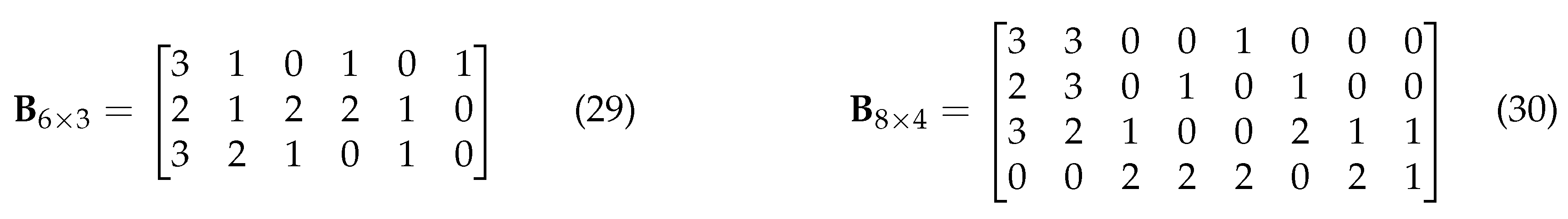
In this section, we use the proposed Mixed-ADC-LS-MIMO PEXIT in the previous section to calculate the iterative decoding threshold of a specific protograph LDPC codes: the one in (29) was designed for LS-MIMO channel [29] and the other in (30) was constructed for AWGN channel [51]. The proto-matrices of the codes are given in (29) and (30). We use the PEXIT algorithm as a powerful tool to theoretically analyze the performance gain between the equal distance and equal weight superposition modulation schemes. Importantly, we demonstrate the significant advantages of mixed-ADC architectures over single-resolution ADC systems.
Figure 5.
Protograph LDPC code base matrices: (a) Base matrix designed for LS-MIMO channels; (b) Base matrix designed for AWGN channels.
Figure 5.
Protograph LDPC code base matrices: (a) Base matrix designed for LS-MIMO channels; (b) Base matrix designed for AWGN channels.
We evaluate a MIMO system with a code structure under four ADC configurations: single 1-bit, dual mixed (, ), triple mixed (, , ), and single 5-bit ADCs. Table 2 compares their decoding thresholds for equal distance and equal weight superposition modulation (SM) schemes. Notably, equal weight SM consistently outperforms equal distance SM, offering 1 dB lower thresholds across all cases. This gap narrows slightly with higher ADC resolution, dropping from 1.19 dB (1-bit) to 0.97 dB (5-bit). Transitioning from a single 1-bit ADC to dual or triple mixed-ADC setups significantly reduces thresholds—by over 1.15 dB and 1.03 dB for equal distance and equal weight SM, respectively. However, the triple mixed-ADC system still lags behind the 5-bit baseline by 1.66 dB (equal distance - ED) and 1.76 dB (equal weight - EW), raising the question of optimal resolution partitioning to balance power and performance.
Table 3 presents results for a MIMO system using a code under four ADC configurations: single 1-bit, dual mixed (, ), triple mixed (, , ), and single 5-bit ADCs. As with the case, equal weight superposition modulation (SM) consistently outperforms equal distance SM, with threshold gaps ranging from 0.99 to 1.12 dB across all modes. Both dual and triple mixed-ADC setups again show significant gains over the single 1-bit ADC baseline. For example, in the equal distance SM case, the triple mixed-ADC achieves a threshold of dB, compared to dB for the single 1-bit ADC—a 0.93 dB improvement.
Table 4 presents decoding thresholds for the protograph code—originally designed for AWGN—under the same MIMO configuration used for the LS-MIMO code. The overall trends mirror those in Table 2: equal weight superposition modulation (SM) consistently outperforms equal distance SM, and both dual and triple mixed-ADC setups yield clear gains over the single 1-bit ADC. However, the code shows consistently higher thresholds across all resolutions. For example, the equal distance SM threshold with single 1-bit ADCs rises from 1.34 dB to 1.68 dB. These results highlight that while performance trends remain consistent, codes tailored to LS-MIMO channels achieve lower thresholds, underscoring the importance of channel-specific LDPC code design.
Table 5 shows the decoding thresholds of the protograph code under the MIMO setup. While the threshold trends remain consistent—improving with mixed-ADC architectures and equal weight SM—the absolute values are higher than those of the LS-MIMO-optimized code. For example, in the single 1-bit ADC case, the equal distance SM threshold is dB, compared to dB for the code (Table 3), reflecting a 0.32 dB performance gap. This further confirms that codes designed for LS-MIMO channels yield better thresholds under identical conditions.
6. Simulation Results
This section presents extensive simulations to validate the theoretical decoding thresholds from the previous section. The setup mirrors earlier experiments, using two MIMO configurations ( and ) and two protograph LDPC codes defined by proto-matrices (29) and (30). Each code has a total length of 2400 bits, constructed via two lifting steps. First, the protograph (with 3 check nodes and 6 variable nodes) is lifted by a factor of 4 using the PEG algorithm [52] to eliminate parallel edges. The second lifting factor is 100, yielding an information block length of 1200 bits. The final LDPC code is formed using circulant permutation matrices using PEG-based selection to eliminate short cycles in the lifted graph.
To begin with, Figure 6 presents the BER performance of various ADC configurations under both equal weight (EW) and equal distance (ED) superposition modulation, using the protograph LDPC code defined by the proto-matrix. The results were obtained for a MIMO system operating with 16-ary superposition modulation. These simulation results are consistent with the theoretical predictions outlined in Table 2. Notably, the EW superposition modulation consistently outperforms its ED counterpart across all ADC setups, with performance gains ranging from approximately 1.0 to 1.8dB at a BER of . This performance advantage aligns closely with the decoding threshold gaps reported in Table 2, where EW modulation showed lower thresholds for all configurations.
In terms of ADC architecture, the triple mixed-ADC configuration (comprising 25 1-bit, 10 2-bit, and 5 5-bit ADCs) achieves a 1.8 dB BER performance gain over the single 1-bit system. The dual mixed-ADC setting also demonstrates a marked improvement over the single one-bit configuration but exhibits slightly inferior performance compared to the triple mixed-ADC scheme. The simulation results confirm that the proposed mixed-ADC receiver design achieves a strong trade-off between performance and energy efficiency, as predicted by the PEXIT-based theoretical analysis. Specifically, the triple mixed-ADC system with EW modulation operates within 1.8 dB of the 5-bit baseline, while the 1-bit system has a gap of more than 3 dB to the 5-bit ADCs, thus validating the effectiveness of the mixed ADC deployment in LS-MIMO systems. It is also observed that the performance gap between equal weight and equal distance superposition modulation decreases as the ADC resolution increases. This trend is evident in both the theoretical decoding thresholds (Table 2) and the BER simulation results (Figure 6), indicating that higher-resolution ADCs reduce the relative benefit of optimal SM weighting due to improved quantization precision.
Figure 7 illustrates the BER performance for the protograph LDPC code defined by the proto-matrix under a MIMO system with a 16-ary superposition modulation scheme. As observed in the previous configuration (Figure 6), the equal weight (EW) superposition modulation consistently outperforms the equal distance (ED) counterpart across all ADC configurations. This trend holds true for single 1-bit ADCs, dual mixed ADCs, triple mixed ADCs, and full-resolution 5-bit ADCs, further confirming the robustness of EW modulation in various quantization environments.
While the performance advantages of mixed-ADC architectures are evident, practical considerations such as hardware cost and power consumption must also be accounted for. One-bit and two-bit ADCs are significantly cheaper and more energy-efficient than five-bit ADCs, which often require complex calibration and consume higher power. Therefore, the triple mixed-ADC design offers a compelling trade-off—delivering near-optimal decoding performance while substantially reducing implementation cost and power usage compared to uniform high-resolution ADC systems.
More notably, by increasing the number of receiver antennas from to , the system experiences a substantial improvement in BER performance across all configurations. The decoding curves for all ADC architectures shift leftward by approximately 2–4 dB, indicating that additional spatial diversity from more receive antennas enhances the detection capability and effectively compensates for quantization noise. This improvement is particularly evident in the low-resolution settings, where the 1-bit ADC system with ED modulation now operates at 0.4 dB for a BER level of in the MIMO configuration, compared to 4 dB in the MIMO configuration.
To demonstrate the performance of the LS-MIMO code and the AWGN code, Figure 8 and Figure 9 illustrate the BER performance of the protograph LDPC code, originally designed for AWGN channels [51], under various MIMO setups and ADC configurations. While the code differs structurally from the protograph used in Figure 6Figure 7, the performance trends remain broadly consistent. Specifically, the benefits of equal weight (EW) over equal distance (ED) superposition modulation are clearly observed across all receiver configurations. Likewise, mixed-ADC architectures continue to demonstrate significant gains over the baseline single 1-bit ADC setup, and increasing the number of receive antennas from to results in a noticeable reduction in the required to achieve the same BER level, reaffirming the spatial diversity gain.
Moreover, the simulation results exhibit good alignment with the theoretical thresholds derived using the modified mixed-ADC PEXIT algorithm. This consistency across different code structures confirms the robustness and adaptability of the theoretical analysis tool in guiding system design and performance prediction. Interestingly, despite the fact that the code contains more variable and check nodes—typically associated with stronger performance in AWGN settings—it exhibits inferior performance compared to the code specifically tailored for low-resolution ADCs in massive MIMO channels. For instance, under identical system parameters, the code consistently achieves lower BER at the same levels than its counterpart. This observation suggests that designing LDPC codes specifically optimized for the characteristics of quantized MIMO channels (e.g., mixed-ADC distortion, spatial correlation) is a worthwhile direction for future research.
7. Conclusion
In this study, we addressed the power constraints of LS-MIMO systems by proposing a hybrid ADC receiver structure integrated with superposition modulation and protograph LDPC codes, which is crucial for future wireless networks such as B5G/6G and IoT. This work confirmed the value of triple mixed-ADC designs through both analytical and simulation-based decoding thresholds. The observed 1.8 dB improvement over 1-bit systems, approaching full-resolution ADC performance, underscores the practical viability of triple mixed-ADC designs. Future directions include optimizing partition strategies and exploring cooperative MIMO under hybrid quantization.
References
- D. C. Araújo, T. Maksymyuk, A. L. F. de Almeida, T. Maciel, J. C. M. Mota, and M. Jo, “Massive MIMO: Survey and future research topics,” IET Communications, vol. 10, no. 15, pp. 1938–1946, 2016.
- K. B. Letaief, W. Chen, Y. Shi, J. Zhang, and Y. A. Zhang, “The roadmap to 6G: AI empowered wireless networks,” IEEE Communications Magazine, vol. 57, pp. 84–90, Aug. 2019.
- Z. Zhang, Y. Xiao, Z. Ma, M. Xiao, Z. Ding, X. Lei, G. K. Karagiannidis, and P. Fan, “6G wireless networks: Vision, requirements, architecture, and key technologies,” IEEE Vehicular Technology Magazine, vol. 14, pp. 28–41, Sept. 2019.
- L. Fan, S. Jin, C. Wen, and H. Zhang, “Uplink achievable rate for massive mimo systems with low-resolution adc,” IEEE Communications Letters, vol. 19, pp. 2186–2189, Dec 2015.
- J. Zhang, L. Dai, X. Li, Y. Liu, and L. Hanzo, “On low-resolution adcs in practical 5g millimeter-wave massive mimo systems,” IEEE Communications Magazine, vol. 56, no. 7, pp. 205–211, 2018.
- C. Zhang, Y. Jing, Y. Huang, and X. You, “Massive MIMO with ternary ADCs,” IEEE Signal Processing Letters, p. 1, 2020.
- T. Liu, J. Tong, Q. Guo, J. Xi, Y. Yu, and Z. Xiao, “Energy efficiency of massive MIMO systems with low-resolution adcs and successive interference cancellation,” IEEE Transactions on Wireless Communications, vol. 18, pp. 3987–4002, Aug. 2019.
- J. Dai, J. Liu, J. Wang, J. Zhao, C. Cheng, and J. Wang, “Achievable rates for full-duplex massive MIMO systems with low-resolution ADCs/DACs,” IEEE Access, vol. 7, pp. 24343–24353, 2019.
- S. Gao, P. Dong, Z. Pan, and G. Y. Li, “Deep learning based channel estimation for massive MIMO with mixed-resolution ADCs,” IEEE Communications Letters, vol. 23, pp. 1989–1993, Nov. 2019.
- L. V. Nguyen, D. T. Ngo, N. H. Tran, A. L. Swindlehurst, and D. H. N. Nguyen, “Supervised and semi-supervised learning for MIMO blind detection with low-resolution ADCs,” IEEE Transactions on Wireless Communications, p. 1, 2020.
- L. Xu, X. Lu, S. Jin, F. Gao, and Y. Zhu, “On the uplink achievable rate of massive MIMO system with low-resolution ADC and RF impairments,” IEEE Communications Letters, vol. 23, pp. 502–505, Mar. 2019.
- D. A. Hoang, H. T. Nguyen, and T. N. Le, “Performance Analysis of Superposition M-ary QAM Modulation in Coded Protograph LDPC MIMO Communication Systems With Low-Resolution ADCs,” IEEE Access, vol. 13, pp. 107410–107428, 2025. [CrossRef]
- T. V. Nguyen, H. D. Vu, D. N. Nguyen, and H. T. Nguyen, “Performance analysis of protograph LDPC codes over large-scale MIMO channels with low-resolution ADCs,” IEEE Access, vol. 7, pp. 145145–145160, 2019.
- Y. Cho and S. Hong, “One-bit successive-cancellation soft-output (oss) detector for uplink mu-MIMO systems with one-bit ADCs,” IEEE Access, vol. 7, pp. 27172–27182, 2019.
- F. Mousavi and A. Tadaion, “A simple two-stage detector for massive MIMO systems with one-bit ADCs,” in Proc. 27th Iranian Conf. Electrical Engineering (ICEE), pp. 1674–1678, Apr. 2019.
- Q. Bai and J. A. Nossek, “Energy efficiency maximization for 5g multi-antenna receivers,” Trans. on Emerging Telecommunications Technologies, 2015.
- H. N. Dang, T. V. Nguyen, and H. T. Nguyen, “Improve uplink achievable rate for massive mimo systems with low-resolution adcs,” in 2020 IEEE Eighth International Conference on Communications and Electronics (ICCE), pp. 99–104, 2021.
- T. Liu, A. Liu, H. Zhang, W. Xu, and H. Lei, “Secrecy performance analysis of mixed-adc/dac cell-free massive mimo in the presence of multiple eavesdroppers,” IEEE Transactions on Communications, vol. 71, no. 3, pp. 1643–1658, 2023.
- H. Wang, Y. D. Zhang, B. Zhang, and J. Wang, “Mixed-adc based pmcw mimo radar angle-doppler imaging,” IEEE Transactions on Aerospace and Electronic Systems, 2023.
- W. Liu, Y. Li, X. Wu, Y. Han, X. Chen, and H. Zhang, “Massive access in extra large-scale mimo with mixed-adc over near-field channels,” IEEE Transactions on Communications, 2023.
- Y. Hu, R. Xie, J. Wu, S. Jin, and H. Li, “Channel estimation for irs-assisted mmwave massive mimo systems in mixed-adc architecture,” IEEE Transactions on Wireless Communications, 2023.
- Y. Chen, Y. Liu, Q. Zhang, L. Li, and X. Cao, “Channel estimation for irs-aided massive mimo systems with mixed-adc architecture,” IEEE Wireless Communications Letters, vol. 12, no. 5, pp. 851–855, 2023.
- Y. Gao, Y. Zhang, J. Yuan, J. Zhang, and W. Zhang, “Channel estimation for mmwave massive mimo systems with mixed-adc architecture,” IEEE Wireless Communications Letters, vol. 12, no. 6, pp. 953–957, 2023.
- A. Elgabli and T. Y. Al-Naffouri, “Hybrid low-and full-resolution adcs in uplink massive mimo systems: Performance analysis and deep learning-based detection,” IEEE Transactions on Communications, vol. 71, no. 5, pp. 2877–2893, 2023.
- Y. Zhao, Y. Wei, and Y.-C. Liang, “Detection of multi-user signals in massive mimo systems with mixed-adc architecture,” IEEE Transactions on Wireless Communications, vol. 22, no. 8, pp. 5004–5018, 2023.
- J. Thorpe, “Low-density parity-check (ldpc) codes constructed from protographs,” IPN Progress Report, pp. 42–154, 2003.
- M. D. Aksun and E. Arıkan, “LDPC code design for 6g wireless,” IEEE Communications Magazine, vol. 59, pp. 76–81, Nov. 2021.
- H. N. Dang, T. V. Nguyen, and H. T. Nguyen, “Improve uplink achievable rate for massive mimo systems with low-resolution adcs,” in 2020 IEEE Eighth International Conference on Communications and Electronics (ICCE), pp. 99–104, 2021.
- H. D. Vu, T. V. Nguyen, D. N. Nguyen, and H. T. Nguyen, “On design of protograph ldpc codes for large-scale mimo systems,” IEEE Access, vol. 8, pp. 46017–46029, 2020.
- P. A. Hoeher and T. Wo, “Superposition modulation: Myths and facts,” IEEE Communications Magazine, vol. 49, pp. 110–116, Dec. 2011.
- J. Luo, Y. Bai, B. Bai, C. Chen, and W. Wen, “A multi-layer superposition modulation scheme to improve the data rate for iot communications,” in Proceedings of the 2023 IEEE/CIC International Conference on Communications in China (ICCC Workshops), (Dalian, China), pp. 1–6, Aug. 2023.
- D. Hao and P. A. Hoeher, “Superposition modulation with reliability-based hybrid detection,” in Proceedings of the 2010 6th International Symposium on Turbo Codes and Iterative Information Processing (ISTC), (Brest, France), pp. 280–284, Sept. 2010.
- Y. H. Choi and S. W. Heo, “A novel decoding algorithm of superposition modulation for cooperative iot system,” in Proceedings of the 2020 IEEE International Conference on Consumer Electronics (ICCE), (Las Vegas, NV, USA), pp. 1–2, Jan. 2020.
- C. Hasan and U. Aygolu, “An incremental relaying approach for superposition modulated cooperative transmission,” in Proceedings of the 2009 IEEE Wireless Communications and Networking Conference (WCNC), (Budapest, Hungary), pp. 1–6, Apr. 2009.
- X. Lu, T. J. Li, and Y. Liu, “Multiuser cooperative transmission through superposition modulation based on braid coding,” in Proceedings of the 2015 IEEE International Conference on Acoustics, Speech and Signal Processing (ICASSP), (South Brisbane, QLD, Australia), pp. 3128–3132, Apr. 2015.
- S. Zhao, X. Ma, and B. Bai, “Decoding algorithms of ldpc coded superposition modulation,” IEEE Communications Letters, vol. 18, pp. 487–490, Mar. 2014.
- M. Srinivasan and S. Kalyani, “Analysis of massive MIMO with low-resolution ADC in nakagami- m fading,” IEEE Communications Letters, vol. 23, pp. 764–767, Apr. 2019.
- H. T. Nguyen, T. A. Ramstad, and I. Balasingham, “Wireless sensor communication system based on direct-sum source coder,” IET Wireless Sensor Systems, vol. 1, pp. 96–104, June 2011.
- D. Hui and D. L. Neuhoff, “Asymptotic analysis of optimal fixed-rate uniform scalar quantization,” IEEE Transactions on Information Theory, vol. 47, pp. 957–977, March 2001.
- W. Fukuda, T. Abiko, T. Nishimura, T. Ohgane, Y. Ogawa, Y. Ohwatari, and Y. Kishiyama, “Low-complexity detection based on belief propagation in a massive mimo system,” in 2013 IEEE 77th Vehicular Technology Conference (VTC Spring), pp. 1–5, June 2013.
- T. Takahashi, S. Ibi, and S. Sampei, “On normalization of matched filter belief in gabp for large MIMO detection,” in Proc. IEEE 84th Vehicular Technology Conf. (VTC-Fall), pp. 1–6, Sept. 2016.
- H. D. Vu, T. V. Nguyen, T. B. Do, and H. T. Nguyen, “Belief propagation detection for large-scale mimo systems with low-resolution adcs,” in 2019 International Conference on Advanced Technologies for Communications (ATC), pp. 68–73, 2019.
- T. J. Richardson, M. A. Shokrollahi, and R. L. Urbanke, “Design of capacity-approaching irregular low-density parity-check codes,” IEEE Transactions on Information Theory, vol. 47, pp. 619–637, Feb. 2001.
- S. ten Brink, G. Kramer, and A. Ashikhmin, “Design of low-density parity-check codes for modulation and detection,” IEEE Transactions on Communications, vol. 52, pp. 670–678, Apr. 2004.
- G. Liva and M. Chiani, “Protograph ldpc codes design based on exit analysis,” in IEEE GLOBECOM 2007 - IEEE Global Telecommunications Conference, pp. 3250–3254, Nov 2007.
- Y. Fang, P. Chen, L. Wang, F. C. M. Lau, and K. K. Wong, “Performance analysis of protograph-based low-density parity-check codes with spatial diversity,” IET Communications, vol. 6, pp. 2941–2948, Nov. 2012.
- T. V. Nguyen and A. Nosratinia, “Rate-compatible short-length protograph LDPC codes,” IEEE Communications Letters, vol. 17, pp. 948–951, May 2013.
- T. V. Nguyen and H. T. Nguyen, “The design of optimized fast decoding protograph LDPC codes,” in Proc. Int. Conf. Advanced Technologies for Communications (ATC), pp. 282–286, Oct. 2016.
- T. Abiko, W. Fukuda, T. Nishimura, T. Ohgane, Y. Ogawa, Y. Ohwatari, and Y. Kishiyama, “An exit chart analysis for belief-propagation based detection in a large-scale mimo system,” pp. 1–5, June 2013.
- H. N. Dang, H. T. Nguyen, and T. V. Nguyen, “Joint detection and decoding of mixed-adc large-scale mimo communication systems with protograph ldpc codes,” IEEE Access, vol. 9, pp. 101013–101029, 2021.
- H. Uchikawa, “Design of non-precoded protograph-based LDPC codes,” in Proc. IEEE Int. Symp. Information Theory, pp. 2779–2783, June 2014.
- X.-Y. Hu, E. Eleftheriou, and D. M. Arnold, “Regular and irregular progressive edge-growth tanner graphs,” IEEE Transactions on Information Theory, vol. 51, pp. 386–398, Jan 2005.
Figure 1.
Block Diagram of Transceiver in Protograph LDPC Coded MIMO Communication Systems with Low-Resolution ADCs: (a) Transmitter uses superposition high-order modulation scheme for bandwidth efficiency. (b) Receiver has three sets of low-resolution ADCs to cut down the power consumption.
Figure 1.
Block Diagram of Transceiver in Protograph LDPC Coded MIMO Communication Systems with Low-Resolution ADCs: (a) Transmitter uses superposition high-order modulation scheme for bandwidth efficiency. (b) Receiver has three sets of low-resolution ADCs to cut down the power consumption.
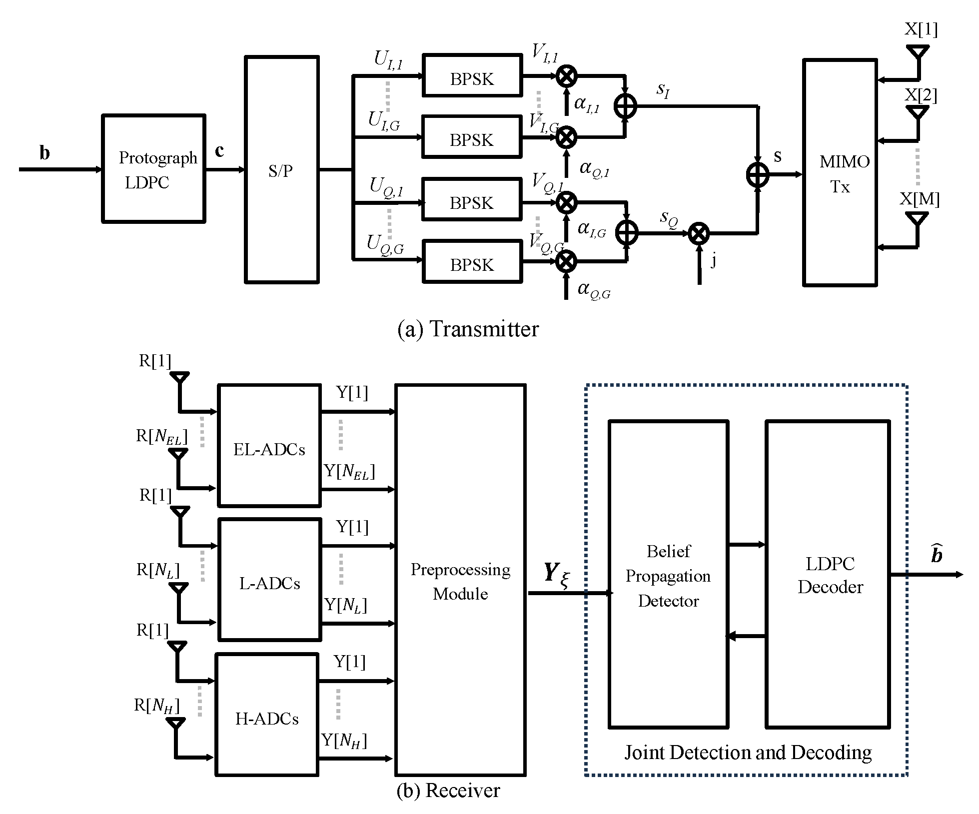
Figure 2.
Double-Layer Graph for Mixed ADC Receiver: The lower layer handles MIMO signal detection using three separate sub-graphs—one for each ADC resolution level (extremely low, low, and high). The upper layer performs message passing for channel decoding.
Figure 2.
Double-Layer Graph for Mixed ADC Receiver: The lower layer handles MIMO signal detection using three separate sub-graphs—one for each ADC resolution level (extremely low, low, and high). The upper layer performs message passing for channel decoding.
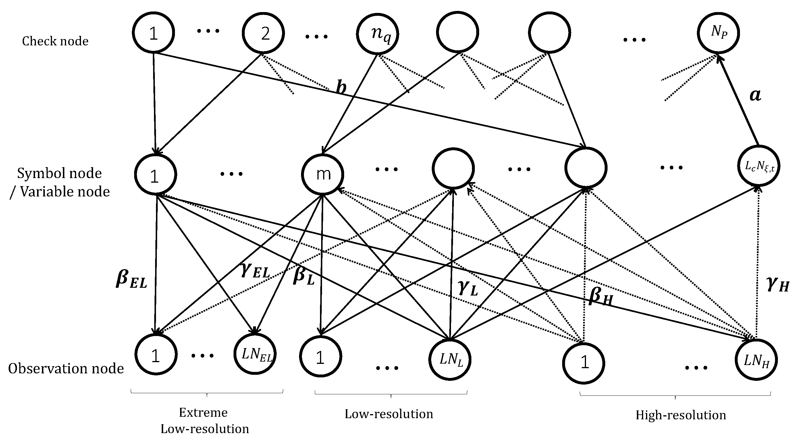
Figure 3.
Forward information flow.

Figure 4.
Backward information flow.
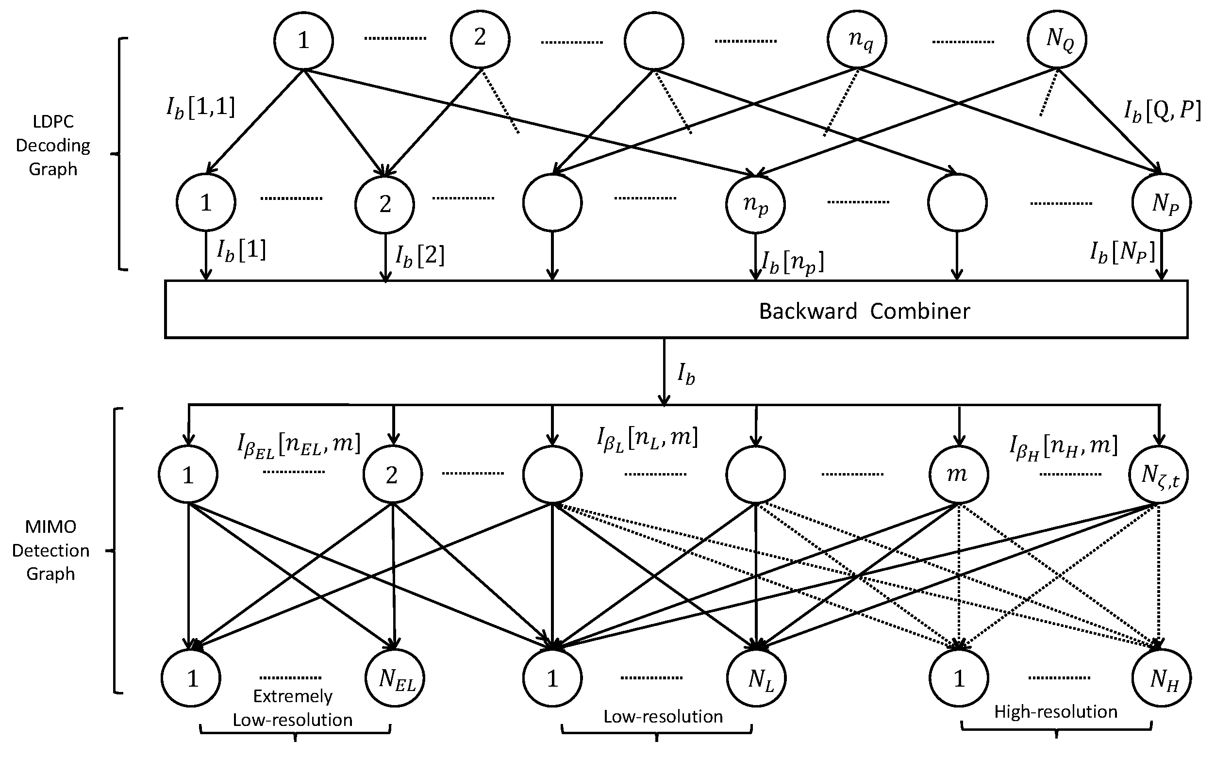
Figure 6.
BER Performance: Protograph LDPC Code of Size (29), Code Length 2400 bits, MIMO , 16-Ary Constellation, 1–5 bit ADCs.
Figure 6.
BER Performance: Protograph LDPC Code of Size (29), Code Length 2400 bits, MIMO , 16-Ary Constellation, 1–5 bit ADCs.
Figure 7.
BER Performance: Protograph LDPC Code of Size (29), Code Length 2400 bits, MIMO , 16-Ary Constellation, 1–5 bit ADCs.
Figure 7.
BER Performance: Protograph LDPC Code of Size (29), Code Length 2400 bits, MIMO , 16-Ary Constellation, 1–5 bit ADCs.
Figure 8.
BER Performance: Protograph LDPC Code of Size (29), Code Length 2400 bits, MIMO , 16-Ary Constellation, 1–5 bit ADCs.
Figure 8.
BER Performance: Protograph LDPC Code of Size (29), Code Length 2400 bits, MIMO , 16-Ary Constellation, 1–5 bit ADCs.
Figure 9.
BER Performance: Protograph LDPC Code of Size (29), Code Length 2400 bits, MIMO , 16-Ary Constellation, 1–5 bit ADCs.
Figure 9.
BER Performance: Protograph LDPC Code of Size (29), Code Length 2400 bits, MIMO , 16-Ary Constellation, 1–5 bit ADCs.

Table 1.
Optimal Values of for different ADC resolution levels [28].
Table 1.
Optimal Values of for different ADC resolution levels [28].
| Resolution | 1 | 2 | 3 | 4 | 5 |
|---|---|---|---|---|---|
| 1.669 | 2.0912 | 2.4613 | 2.7909 | 3.0285 | |
| 0.6261 | 0.8796 | 0.9628 | 0.9885 | 0.9936 |
Table 2.
Decoding thresholds for code under MIMO with various ADC setups.
| Resolution | ED | EW | Gap |
|---|---|---|---|
| Single 1-Bit ADCs | 1.34 | 0.15 | 1.19 |
| Dual Mixed ADCs | 0.77 | -0.34 | 1.11 |
| Triple Mixed ADCs | 0.19 | -0.88 | 1.07 |
| Single 5-Bit ADCs | -1.57 | -2.54 | 0.97 |
Table 3.
Decoding thresholds for code under MIMO with various ADC setups.
| Resolution | ED | EW | Gap |
|---|---|---|---|
| Single 1-Bit ADCs | -0.79 | -1.91 | 1.12 |
| Dual Mixed ADCs | -1.39 | -2.46 | 1.07 |
| Triple Mixed ADCs | -1.72 | -2.77 | 1.05 |
| Single 5-Bit ADCs | -3.35 | -4.34 | 0.99 |
Table 4.
Decoding thresholds for 8×4 code under 10×40 MIMO with various ADC setups.
| Resolution | ED | EW | Gap |
|---|---|---|---|
| Single 1-Bit ADCs | 1.68 | 0.41 | 1.27 |
| Dual Mixed ADCs | 1.09 | -0.09 | 1.18 |
| Triple Mixed ADCs | 0.49 | -0.64 | 1.13 |
| Single 5-Bit ADCs | -1.29 | -2.33 | 1.04 |
Table 5.
Decoding thresholds for 8×4 code under 10×60 MIMO with various ADC setups.
| Resolution | ED | EW | Gap |
|---|---|---|---|
| Single 1-Bit ADCs | -0.47 | -1.66 | 1.19 |
| Dual Mixed ADCs | -1.09 | -2.22 | 1.13 |
| Triple Mixed ADCs | -1.43 | -2.54 | 1.11 |
| Single 5-Bit ADCs | -3.08 | -4.12 | 1.04 |
Disclaimer/Publisher’s Note: The statements, opinions and data contained in all publications are solely those of the individual author(s) and contributor(s) and not of MDPI and/or the editor(s). MDPI and/or the editor(s) disclaim responsibility for any injury to people or property resulting from any ideas, methods, instructions or products referred to in the content. |
© 2025 by the authors. Licensee MDPI, Basel, Switzerland. This article is an open access article distributed under the terms and conditions of the Creative Commons Attribution (CC BY) license (http://creativecommons.org/licenses/by/4.0/).
Copyright: This open access article is published under a Creative Commons CC BY 4.0 license, which permit the free download, distribution, and reuse, provided that the author and preprint are cited in any reuse.


