
Submitted:
17 July 2025
Posted:
17 July 2025
You are already at the latest version
Abstract
This study presents the development of an open-source Driver-in-the-Loop simulation platform, specifically designed to test and analyze advanced automated driving functions. We emphasize the creation of a versatile system architecture that ensures seamless integration and interchangeability of components, supporting diverse research needs. Central to the simulator’s configuration is a hexapod motion platform with six degrees of freedom, chosen through a detailed benchmarking process to ensure dynamic accuracy and fidelity. The simulator employs a half-vehicle cabin, providing an immersive environment where drivers can interact with authentic human-machine interfaces such as pedals, steering, and gear shifters. By projecting complex driving scenarios onto a curved screen, drivers engage with critical maneuvers in a controlled virtual environment. Key innovations include the integration of a motion cueing algorithm and an adaptable, cost-effective open-source framework, facilitating collaboration among researchers and industry experts. The platform enables standardized testing and offers a robust solution for the iterative development and validation of automated driving technologies. Functionality and effectiveness were validated through testing with the ISO lane change maneuver, affirming the simulator’s capabilities.
Keywords:
driving simulator
; XiL-simulation
; automated driving
; motion platform
; validation
1. Introduction
Driver-in-the-Loop (DiL) simulators incorporate human drivers into the simulation process, enabling real-time interaction and feedback mechanisms. These simulators are particularly beneficial for evaluating Advanced Driver Assistance Systems (ADAS) [1,2], as well as autonomous driving systems, since they offer standardized testing environments that comply with safety regulation requirements [3,4]. Moreover, DiL simulators play a crucial role in assessing vehicle and hardware performance [5,6] and serve as valuable tools for training and educational purposes [7,8].
The primary objective of our work is to present the development of a versatile DiL simulation platform, specifically designed to test and analyze automated driving functions. Our approach emphasizes an open-source architecture, ensuring broad accessibility and flexibility. This aligns with the growing demand for cooperative and multidisciplinary research endeavors that can adapt to evolving technological landscapes.
Leveraging a hexapod motion platform, our simulator supports comprehensive interaction with complex driving scenarios, including critical events such as the ISO lane change test, within a meticulously calibrated virtual environment. This configuration ensures the accurate simulation of diverse driving conditions, thus enhancing the realism and fidelity essential for precise evaluations. Additionally, by maintaining a balance between performance and ease of use, our platform promises to be a powerful tool for both research and industrial applications, encouraging the continuous advancement of automated and autonomous driving technologies.
2. Related Work
DiL simulators are designed with varying attributes and structural characteristics to meet key requirements, determined by the type of use case. Those key requirements address the following specific aspects of the simulation environment:
Realism and Fidelity: Ensuring that the simulator provides realistic cues and feedback to the driver is imperative. This involves precise vehicle dynamics, authentic motion feedback and high-quality visual and auditory environments [9,10]. The fidelity and realism of a simulator are intrinsically linked to both absolute and relative validity, and the exploration and comprehension of this relationship remain active areas of research [10]. It is crucial to define the necessary level of required realism and validity for each testing scenario, acknowledging that achieving 100% realism is neither required nor practically feasible. As an example, a DiL simulator dedicated specifically to vehicle dynamics necessitates a higher degree of dynamic accuracy and fidelity compared to one designed primarily for testing certain types of ADAS. Regarding the DiL simulator that is developed in this work, it requires the representation of dynamics from often occurring driving scenarios in urban areas, highway roads and rural areas including edge cases like a lane change maneuver. Additional to the movement, a realistic look and feel is required, as well as realistic visual feedback.
System integration and open architectures: This involves the seamless integration of various hardware and software components, typically through modular and scalable architectures [5,11]. As illustrated in common architectural frameworks, it is essential to design these systems with the driver as the central element in a feedback loop, ensuring that inputs and outputs are linked to the driver’s interactions and responses [12,13,14].
Latency and Real-Time Performance: Minimizing system delays is crucial to ensure that driver input is accurately reflected in the simulation in real time [15]. Potential disturbances can arise from various factors. These include physical factors (spring and damper effects, inertia, friction), electrical issues (signal rate limitations, errors, disturbances) and computational challenges (signal and data processing speeds, data exchange protocols).
3. System Architecture Design
Considering the requirement for an open system mentioned in Chapter Section 2, the developed system architecture for the driving simulator is depicted in Figure 1, encompassing various subsystems that work together to create a realistic driving simulation. Key elements of this architecture include the Human-Machine Interface (HMI), graphics interface, vehicle- /environment-simulation, simulation-data interface, motion platform control software, the physical motion platform, and the human driver.
In the application case of a DiL simulation, the HMI is used by the driver through the operation of pedals, steering wheel, gear shifter and other input devices to send control commands to the vehicle represented in the simulation. Within the simulation, the dynamic behavior of the vehicle, based on predefined vehicle and environment models, is graphically displayed through the graphics interface. Furthermore, feedback cues such as steering wheel torque (also known as force feedback) or pedal force are sent back to the driver, depending on the underlying calculation model and driving conditions. Additionally, the generated vehicle telemetry data—especially in the form of translational accelerations and rotational velocities—is transmitted as a signal to the simulation-data interface. A central component of the simulation-data interface is the Motion Cueing Algorithm (MCA), which converts the simulated vehicle telemetry into target positions for the motion platform. These motion cues serve as feedback for the driver. A significant distinction from conventional architectures is the integrated interface for sensors, which allows for the extraction of actual motion plattform movements or driver behaviour using electroencephalography (EEG), electrocardiogram (ECG), or eye-tracking devices. By adding diagnostic and monitoring software interfaces, the data can be processed and evaluated in the context of the simulated driving scenario.
Overall, the open system architecture enables a modular approach, where each interface can be replaced by another. This supports comparative tests and studies of different MCA, HMI, as well as motion platforms and vehicle-/environment simulations.
Additionally, real vehicle hardware and software can be integrated to enable X-in-the-Loop (XiL) testing, fostering collaboration across various domains and technologies. As part of this effort, the conceptual integration of a Speedgoat HiL simulator has been investigated and is planned for implementation in the near future. This integration will enable real-time simulation and emulation of autonomous driving functions, hardware-based bus communication, and restbus simulation. The system is based on a Speedgoat 38U rack configuration, featuring two performance and one baseline real-time target machine enabling rapid control prototyping. It supports high-speed Ethernet communication (UDP, TCP/IP, EtherCAT, XCP), provides eight CAN interfaces (CAN, CAN-FD, CANopen), 14 digital I/O channels, 16 analog I/O channels, as well as PWM input and output channels. In addition, the platform includes an AI-ready, freely programmable FPGA to support advanced processing and custom interface development.
4. Development
4.1. Implementation of the Driving Simulator Operating Environment in Simulink
Implementing the concept of the system architecture, the Driving Simulator Operating Environment (DSOE) is developed using Matlab Simulink R2022b (see Figure 2). Similar to the main architecture principle shown in Figure 1, HMI signals from shifter (1), pedals (2), and steering wheel (3) are transmitted to the vehicle-/environment simulation (4). This simulation operates using IPG CarMaker 12.0 and its Simulink interface, CarMaker4Simulink. The simulated vehicle telemetry signals are sent to the simulation data interface (5), where a Classical Washout Algorithm (CWA) scales, filters, and integrates the data before transmitting it to the motion platform control software. This is achieved by integrating the ForceSeatMI API (a machine interface from the company that developed the platform) into a S-Function block. In this application, the motion platform control software is a standalone solution (not within Simulink) and receives the required positions, controlling the platform’s end effector to generate movements.
Diagnostics and monitoring software is added in two ways. The first involves adding internal sensors (6) that monitor objects and variables defined through the vehicle/environment simulation. The second involves integrating external sensors (7) using Vector’s CANopen APIs, allowing sensors to be accessed via CANopen. In both cases, the data is stored in workspace variables and can be accessed immediately after a simulation. The presented DSOE implementation enables testing of the overall system architecture concept. To ensure real-time performance during simulations, each interface task is managed by separate computers using UDP and ROS 2.
4.2. Motion Platform Choice
Based on the previously established criteria, the hexapod motion platform PS-6TL-800 from Motion Systems was chosen. In addition to fundamental requirements such as payload capacity, cost considerations, usability and functional safety, specific demands concerning immersion and realism were also addressed. These include the need to provide realistic motion feedback across various typical driving scenarios, effectively distinguish between normal driving conditions and edge cases, and enhance the immersion level and sensitivity of test drivers to hazardous scenarios. Consequently, it was crucial to compare the dynamic characteristics of each potential motion platform to ensure these requirements were met.
In translational platform dynamics, there is a notable interdependency among displacement, velocity and acceleration. Predominant algorithms, including the CWA, provide certain motion cues through acceleration. However, due to the limitations in platform dynamic range, both the duration and efficacy of these cues are constrained. Consequently, in vehicle simulations, medium to high frequency and initial acceleration scenarios (such as those from transient vehicle responses) are cued through translational platform dynamics. This is also known as acceleration-onset cueing [16].
To accurately assess the translational behaviour, examining merely the static characteristics would be insufficient. An analysis encompassing the interdependencies of displacement, velocity and acceleration is necessary. Therefore, a comprehensive approach similar to [17] accompanies the benchmarking of motion platforms. For the benchmark, 20 hexapod motion platforms were initially examined, out of which nine were selected for further consideration due to data availability and alignment with the previously stated requirements. The detailed benchmark data can be found in Table A1.
Figure 3 illustrates the varying dynamic longitudinal and lateral capabilities concerning a single, undisturbed degree of freedom from a standstill, using the relationship between frequency f and limiting nominal platform position , velocity and acceleration (c.f. [17]):
The acceleration amplitudes are plotted in a double logarithmic scale over frequency. The evaluated hexapod can reproduce all combinations of acceleration amplitudes and frequencies that fall below each line. For clarity, only one of the highest and one of the lowest achieving platforms are depicted to establish the benchmark boundaries. Within these boundaries, the PS-6TL-800 is displayed, demonstrating that it ranks among the better-performing platforms in this analysis.
The available longitudinal and lateral accelerations are initially constrained by a frequency-independent maximum acceleration of , as represented by the horizontal line. For these one-dimensional motions, the velocity can be determined according to Equation 2 as the time integral of the product of acceleration and angular frequency:
By rearranging and substituting the maximum velocity, as well as using , the maximum lateral acceleration as a function of acceleration frequency f can be represented as shown in Equation 3 (c.f. [17]):
At medium frequencies (approximately to for longitudinal and about to for lateral), the displayable acceleration amplitudes decrease and are constrained by the maximum platform velocities and . At lower frequencies, specifically up to 0.15 Hz for longitudinal motion and 0.8 Hz for lateral motion, the nominal acceleration of is limited by the maximum displacement boundaries of the platform. This constraint arises because the frequency dependency is squared as a result of double integration of acceleration over time
Subsequently, lower frequency accelerations, such as quasi-static vehicle behavior during prolonged turns or constant cornering, are depicted by algorithm components like the tilt coordination of the CWA. This approach is subject to known limitations arising from human perception and platform tilt angles. To assess the effectiveness of acceleration representation through tilt coordination, the graphs illustrate the capabilities outlined in Equation 5 (c.f. [17]):
Regarding [18], even though platforms can achieve greater rotational angles, the maximum tilt angle is restricted to to prevent false cueing. The graphs illustrate displayable maximum accelerations of approximately 3.36 m/s² for frequencies up to about 0.02 Hz; beyond this threshold, they are constrained by the perception threshold for rotation rates of . As frequency increases, the maximum acceleration decreases, primarily due to the rotational acceleration perception threshold of [19].
In the context of rotational dynamics, typical values for roll and pitch accelerations observed in vehicles as in [20] are compared against the maximum rotational performance of the platform. Generally, in vehicle dynamics applications, the roll and pitch movements are expected to be displayed without any need for scaling or filtering [17]. Consequently, the evaluation of rotational dynamics is conducted through straightforward comparisons of the peak angular velocities and accelerations, with results depicted in Figure 4. The diagram illustrates the maximum rotational dynamics of both the highest and lowest performing platforms, along with the average performance across all benchmarked models. The characteristic angular values of the PS-6TL-800 are highlighted in blue, indicating that it consistently exceeds the average in each movement category, thereby classifying it among the better-performing platforms.
4.3. Driver’s Cabin and HMI Design
The main task of the driver’s cabin is to create a realistic and immersive driving environment that gives participants the sensation of being in a real vehicle. Utilizing the dimensions of an actual vehicle is unparalleled in replicating the interior space of a real vehicle and allows for the integration of genuine HMI and thus simulation interfaces.
For this purpose, the front half of a Kia XCEED 2022 was prepared to serve as the cabin of the simulator. To reduce weight, unnecessary components were removed from the vehicle. The preparation process involves several meticulous steps; First, the rear interior section was disassembled using a 4-post lift. Following this, the headliner, pillar panels, and panoramic glass sunroof were removed. Subsequently, the underbody panels, rear doors, and side sills were disassembled. Afterward, the drivetrain, including the engine and transmission, was dismantled, and the fuel tank and lines were removed. The vehicle was moved to a scissor lift, where the subframe, steering, and all parts of the front axle were disassembled. As shown in Figure 5, the rear was prepared to be separated from the front section, ensuring that the driver’s cabin remains intact. The rear section was closed off to maintain structural stiffness. The construction of the cabin mounting took place, designed to comply with the motion platform’s requirements for maximum payload and moment of inertia. The net weight of the constructed cabin is 497 kg, providing space for up to two individuals, each weighing up to 100 kg. Additionally, the cabin was equipped to integrate various HMI components and measurement devices as defined in the system architecture and Figure 6, further enhancing its realistic and immersive qualities.
4.3.1. HMI Architecture Design
The HMI architecture, depicted in Figure 7, is comprised of several key components: a sensor, an actuator (such as in the case of a force feedback wheel or haptic pedals), a microcomputer, and the DSOE that runs on a computer.
Initially, raw digital or analog sensor values are extracted and processed. These signals are communicated to the HMI computer using Microsoft’s HID-library. The Simulink DSOE contains embedded S-Functions that facilitate the operation of the HID-Interface. Subsequently, the data is translated into vehicle control signals suitable for the simulated vehicle. The method of data transfer from the microcomputer to the DSOE is contingent upon the specific type and transfer rate required. Depending on these factors, different communication protocols such as CAN, USB, or Ethernet can be employed to ensure efficient data transmission. In future iterations of this setup, a centralized HMI/sensor computer is envisioned. This centralized system would process all incoming data and distribute it to the desired nodes, thereby streamlining operations and potentially enhancing system efficiency and performance.
4.3.2. Pedals
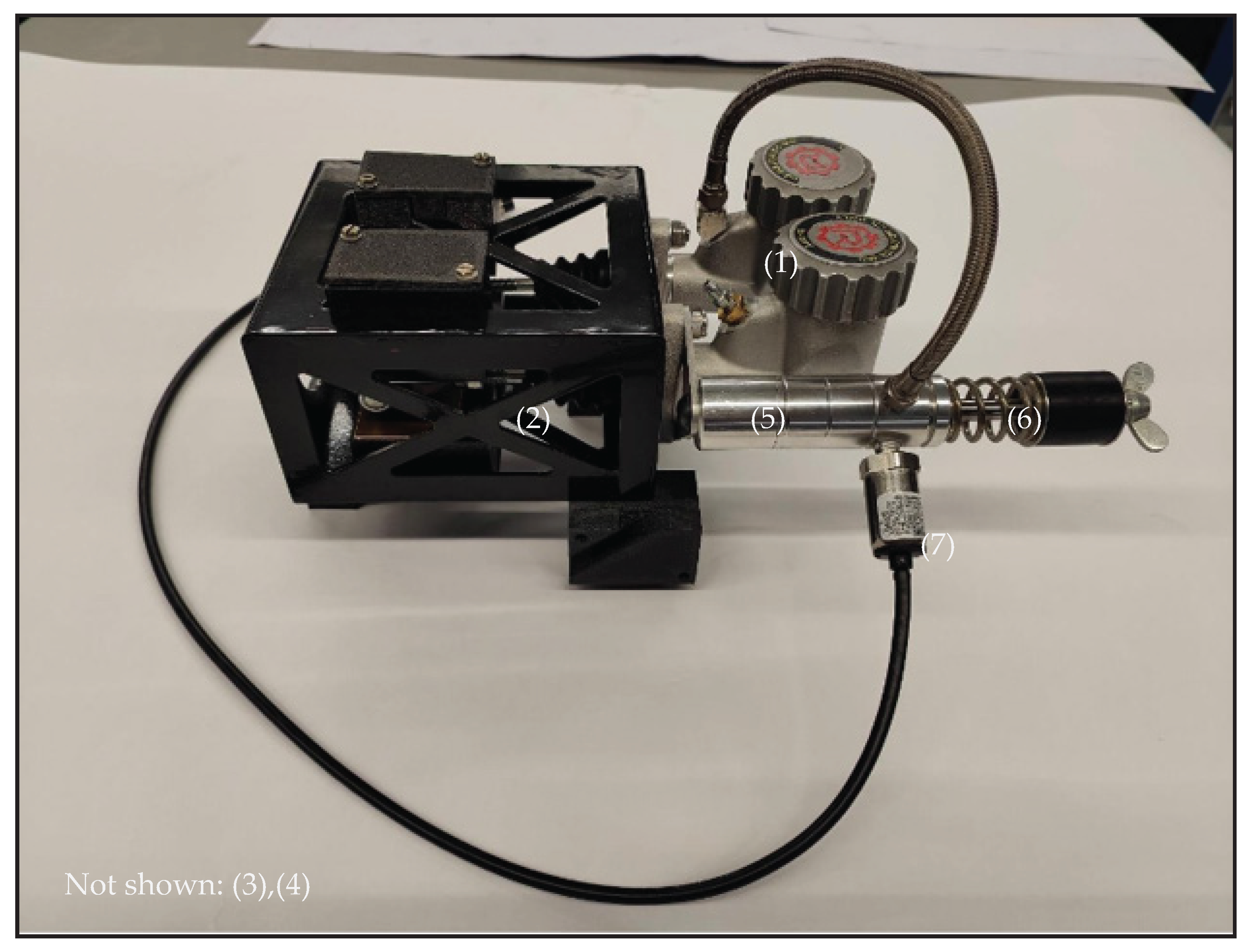
Figure 8 illustrates the integrated brake pedal system. The foundational hardware is the Ricmotech GTpro3 sim-racing braking system by Tilton. The brake cylinders (1) and the secondary cylinder (5) are retained in this system, including the pressure sensor (7). The original pedal assembly is not used in the simulator. Instead, both brake cylinders are interconnected through a balance bar (2), which enables the adjustment of brake balance between them. The primary distinction between the brake cylinders is the internal cross-section of their pressure chambers. The balance bar can be operated using a brake balance adjuster (3), offering the significant advantage of allowing adjustments from the driver’s seat without modifying the installed brake pedals. This adjustment capability extends to being adjusted while driving, which is advantageous for direct comparisons.
The pedal force is conveyed to the brake cylinders via a push rod (4) that is guided by 3D-printed bearings. Both brake cylinders are filled with oil and one is hydraulically connected to the secondary cylinder. This secondary cylinder features an extended piston rod that retracts during use and is surrounded by interchangeable spring elements (6) that counteract its movement, creating pedal resistance. Adjustments to the balance bar and variations in the spring elements at the secondary cylinder can be made to influence the brake pedal feel. Additionally, the pressure sensor can output a signal to measure the brake pressure, allowing for the integration of these signals into the simulation to control the simulated vehicle by using the Ricmotec GTpro3 pedal control unit. During calibration, various spring elements are tested, allowing for the deduction of an initial pedal force-travel characteristic curve.
In addition, the original accelerator pedal is used. To achieve this, the pedal’s integrated sensor circuit is electrically tapped. The signals are analog voltage signals and are directly compatible with the previously described pedal control unit.
Figure 9.
Implementation of the brake system hardware. (1): brake cylinders, (2): balance bar, (3): brake balance adjuster, (4): push rod, (5): secondary cylinder, (6): spring elements, (7): pressure sensor.
Figure 9.
Implementation of the brake system hardware. (1): brake cylinders, (2): balance bar, (3): brake balance adjuster, (4): push rod, (5): secondary cylinder, (6): spring elements, (7): pressure sensor.
4.3.3. Steering
Regarding Figure 10, the steering system is built around the VRS DirectForce Pro Wheel Base, a force-feedback motor with integrated control electronics designed for digital motorsport applications. This system consists of an AC servomotor with an integrated encoder (1) and a controller (2), which together form the foundation of the operation. The motor and encoder are connected to the controller via separate signal cables (3), and the controller itself is powered by its own dedicated power supply (5). To integrate the system into the simulator, the controller is linked using a USB interface (4), which facilitates software communication for controlling up to 25 Nm of torque and capturing wheel angle signals. To ensure compatibility with the existing setup, the original steering column (6) is preserved and the steering wheel (7) is mounted at the original position on the input shaft of the motor. The setup retains the original mounting and adjustment options of the steering wheel, allowing for flexible customization for testing purposes. A custom-manufactured connector securely fastens the steering column to the input shaft of the servomotor, ensuring reliable operation.
Additionally, custom-developed steering system software enables the parameterization of maximum angles through stop-limitations, the conversion of angles and torques in the output, and further processing within the HMI, a topic that will be detailed in future publications.
4.3.4. Gear-Shifter
Figure 11 illustrates the operation method of the gear shifter. To ensure the usability of the gear-shifter lever (1), a push button switch (2) and a linear potentiometer (3) are integrated into its mechanical assembly. These components generate the analog voltage signals and that are connected to the analog inputs of an Arduino microcontroller. The microcontroller code processes these signals and their intervals, interpreting them to identify the drive step selected by the lever. The derived positions are outputted as HID joystick signals, providing an effective method for seamless integration with various simulation software.
4.3.5. Cockpit-Dashboard
The factory-installed digital dashboard was replaced with a more advanced display featuring enhanced video output capabilities. The implemented display shown in Figure 12 receives its video signal from a Raspberry Pi, which can output both images and animations of the speedometer, along with additional user interface features. Power is provided via a USB connection linked to a DC/DC converter that supplies an output voltage of 5 V. The video signal is transmitted through a HDMI cable.
4.3.6. Measurement Onboard Computer
During the integration of a measurement unit within the driving simulator, multiple hardware solutions were evaluated to identify the most suitable option. Initially, three measurement systems were considered: measurement cards, micro-computers (e.g., Raspberry Pi, Arduino), and rugged computers.
Measurement cards offer precise signal acquisition and cost-effective integration into existing computer systems. However, they are challenged by long and interference-prone cable connections, limited expandability, and inadequate capabilities for handling control tasks within the simulator.
Micro-computers, such as Raspberry Pi and Arduino, provide lightweight, compact, and economical solutions suitable for specific applications. Nevertheless, their limited computing power, memory capacity, and connectivity restrict their ability to simultaneously manage complex control and measurement tasks.
In contrast, rugged computers meet all the necessary requirements, including automotive grade interfaces, data acquisition, signal processing, control, and live monitoring. Their integration within the driver’s cabin minimizes cable runs and reduces mechanical stress. While they are notably heavier and require specific measures for safe installation, their advantages make them indispensable for advanced simulation environments.
Specifically, the OnLogic Karbon 804 series rugged computer was selected for its robust performance in managing data generated by the HMI and various sensors. It serves as a crucial interface with the simulator’s main computing systems and is capable of logging and transferring data from simulations, the HMI, and sensors such as cameras, LiDARs, and bio-signals like EEG and ECG. Additionally, it provides CAN interfaces, facilitating the integration of control units into the simulator’s bus system for Hardware-in-the-Loop (HiL) testing. The chosen setup closely emulates real vehicle testing conditions, where rugged computers are standard equipment.
4.4. Visual Environment Design
In the field of visual environments for simulation purposes, two primary types emerge: screens and virtual reality (VR) goggles. VR goggles require minimal hardware, offering seamless integration and a comprehensive field of view (FOV). Additionally, they provide a cost-effective hardware solution [21]. Screens, including projector screens, present advantages such as less long-term stress for the subject compared to VR goggles [22]. They are non-invasive, allowing drivers to maintain a free head and face, thereby enhancing monitoring capabilities through driver monitoring systems utilizing cameras and lidar sensors.
To determine the optimal projector type and positioning, a CAD model was utilized. Considerations beyond the obvious specifications, such as maximum framerate and resolution, include the projection rate, field of view within the driver’s cabin, platform motion—which influences visual immersion—the covering of projected images by driving simulator components, and spatial efficiency. These dependencies are illustrated in Figure 13. Developing the visual screen involves selecting projectors and determining screen dimensions. To represent the best compromise along these factors, the chosen visual environment features a projector screen with a 220° FOV, a diameter of 5 m, and a height of 3 m, accompanied by three projectors.
Figure 14 illustrates the results of the CAD-based measurements. The process began with the construction of the simulator model using the dimensions and dynamics of the motion platform as well as the dimensions of the driver’s cabin. Various projector types and their characteristics, such as throw distance and vertical offset, were considered. The dimensions of the screen were modeled according to the available laboratory space, and the projectors were positioned to ensure full screen coverage. Different projector types were compared against each other by modeling the projection beam, considering factors such as focal length, aspect ratio, vertical offset and the distance to the screen. This information was incorporated into the CAD model, allowing for the generation of a rectangular image within the virtual space.
The image width W is calculated using the ratio between the projection distance d and the throw ratio R:
Given the standard aspect ratio for all benchmarked projectors of R= 16:9 and varying distances d, W is determined by
The depending image Height H is then calculated by
Connecting lines are drawn from the projector’s lens to the corners of the generated image, illustrating the projector’s light beam. This effectively demonstrates the geometric spread of light as it diverges from the lens to encompass the projected image. By incorporating these calculations into the CAD model, a comprehensive visualization of the projector’s beam was achieved, facilitating the consideration of potential obstructions, such as the driver’s cabin, which could obscure projector beams and cast shadows on the screen. Additionally, the human FOV according to [23] is projected from the driver’s seat through the car’s windshield onto the screen, and the coverage of this FOV on the screen is assessed. Evaluations are performed for various angular positions on the motion platform. The translational components are relatively minor and can therefore be omitted. Table 1 presents the measurement results, detailing the starting angle of the FOV cut-off and the percentage of maximum cut-off at the maximum angle. The percentage of cut-off is calculated by the ratio of the area of the human FOV outside the screen boundaries with the area of the original full human FOV.
Additionally, the graphical analysis depicted in Figure 15 employs the CAD model to examine the projections and potential shadow casting. The analysis reveals that while shadows are indeed cast due to the intersection of the light beam with the driver’s cabin in the chosen projector arrangement, these shadows are minimal and lie outside the driver’s FOV.
After constructing and setting up the visual environment, the modeled visual pre-considerations were validated. Figure 16 demonstrates that the assumptions made during the development phase are accurate and that the requirements are being met. In conclusion, although the FOVs are partially out of the area of the projected image, this occurred only at high motion platform angles that are rarely encountered during simulation operations. Subsequent development steps involve the transformation of the graphic image output, including curving and edge blending, which are not covered in this work.
5. Testing and Validation
A ISO 3888-2 double lane change driving scenario was utilized during the pre-parametrization phase, simulation stage, and ultimately for validation purposes. The double lane change was selected due to its status as a standard for vehicle dynamics testing, providing typical dynamics that are also necessary for simulating ADAS edge testing cases. This includes scenarios such as evading objects or executing emergency braking and lane change maneuvers, thus offering a solid foundation for further research.
The scenario was integrated by the simulation data interface of the DSOE using IPG CarMaker 12.0, with simulation and motion cueing data referenced in Table A2. In this study, the vehicle was operated by the user and the telemetry data output during the simulation was transferred to the Acceleration Control Engine (ACE), a CWA developed by the company that created the motion platform. Regarding the system architecture shown in Figure 1 the ACE acts as the simulation data interface. To compare previous assumptions with the real test results, a simulated model of the hexapod was employed to assess the system’s behavior. This model was integrated into the DSOE at the motion platform interface, enabling comprehensive testing of each component’s functionality and usability, as well as evaluating how effectively the components work together within the DSOE. Incorporating functionalities from the platform control software, it calculates the needed length of each of the six linear actuators to provide the required position using inverse kinematics. The multibody dynamics and kinematic dependencies were developed using Simscape. The model is fully parametrizable and offers adjustments in platform dimension, location of masses, inertias and friction effects. For the investigations in this work, only point masses and dimensions were designed, excluding friction and inertia effects. The main purpose of the hexapod model was to provide visual information about the platform’s behaviour, ensuring qualitatively correct movement and monitoring the percentage of deviations from the platform’s calculated minimum and maximum leg lengths during a specific scenario. The real motion platform PS-6TL-800 was also integrated into the DSOE’s motion platform interface. By utilizing its internal motion sensors through the diagnostic interface, the movements of the motion platform were measured and extracted.
Figure 17, Figure 18 and Figure 19 illustrate the dynamics resulting from the simulated maneuver. They show noticeable changes in roll and yaw dynamics and the lateral movement (sway) of the platform. Since the lane change maneuver primarily involves lateral dynamics and exhibits minimal longitudinal acceleration and vertical displacement, significant pitch, surge, and heave movements were excluded from the scope of evaluation. The simulated motion platform operates within the DSOE and successfully replicates the platform motion signals during simulation. As expected, the simulated values match the output from the ACE acting as the simulation data interface. According to the motion platform’s static limits (indicated by the red dashed line), the system boundaries are respected, with no exceedances observed throughout the driving simulation. The measured platform values are qualitatively accurate, as they show a similar trend to the simulated and input signals, though they exhibit a maximum delay of ca. 27 ms. Such a delay was to be expected, as the simulated model does not account for inertias, friction, or other disturbances in the transfer function.
6. Conclusions/Discussion
In this work, a dynamic DiL-simulator was designed, constructed and tested. The study underscored the importance of meticulously defining requirements and designing a robust architecture from the outset. It demonstrated the value of hardware pre-evaluation through benchmarking, where datasheet values of motion platforms were contextualized against each other. The construction and design process was notably hardware-centric, showcasing the potential to modify and integrate real vehicle components into the DiL system. For the visual environment, a CAD-based method was presented to design it without conflicts, making it possible to measure the system quality based on the coverage degree of the projection on the screen and its alignment with the FOV. The implemented DSOE software framework, characterized by its open architectural logic, enables the interchangeability of subsystems. A simulated ISO lane change test validated the simulator’s full functionality, proving the system’s capability and effectiveness.
The open-source DiL simulation platform highlights its significant potential in testing vehicle systems, particularly human-machine interaction and ADAS. The integration of a 6-DOF hexapod platform combined with the CWA enables realistic driving experiences, critical for evaluating and developing advanced automated driving functions.
To enhance the effectiveness of comparing different motion platforms, more comprehensive data is essential. Current reliance on static values is insufficient. Instead, it requires insight into interdependencies among DOF and frequency. Latency considerations are also frequently overlooked, yet are critical for accurate assessment. Many crucial values can only be obtained once the platform is operational and measurements are conducted, underscoring the necessity for motion platform datasheets to be more precise, detailed, and transparent.
During development, initial motion cueing parameters have been established, yet further refinement is required to optimize platform performance. It is essential to simulate driving scenarios tailored to specific use cases, which necessitates considering dynamic rather than static constraints. Presently, the lane change maneuver is predominantly cued through angular movements like roll and yaw, due to sensitive tilt coordination parametrization. However, lane changes provide opportunities to amplify translational acceleration cues and reduce tilt coordination.
Although a system movement inertia was expected, a delay of 27 ms is relatively higher compared to previously conducted tests. These earlier tests were implemented with less complex operating systems that demanded lower computational capacity, as they did not involve vehicle environment simulation or HMI signal processing. Therefore, it is reasonable to assume that the observed delays or latency issues are attributed to an overloaded computational system. Future refinements of the DiL system plan to distribute the computational tasks of the DSOE across multiple dedicated computers. This approach is expected to ideally reduce the delay to the levels observed in previous studies.
Overall, this study showcases the technical advancements of the simulator’s architecture and its open-source approach, offering a versatile and cost-effective solution for standardized testing. This platform serves as a valuable tool for researchers and industry experts aiming to develop and test automated driving technologies through flexible and comprehensive testing methods.
7. Future Work
Future efforts will focus on expanding the HiL and Software-in-the-Loop (SiL) testing capabilities within the DiL framework. This expansion aims to fully utilize the onboard logging network, enabling more detailed and comprehensive data collection for driver monitoring system and behaviour studies. In addition, we intend to document and publish the steering wheel software development process and provide access to the source code. This will facilitate further innovation and collaboration in the field of HMI research. Furthermore, we aim to enhance the adjustability of the HMI devices. For the steering wheel, this entails having full adjustability of the steering shaft and universal joints, allowing it to function as an in-the-loop test bench for power steering applications. For the gas and brake pedal unit, the introduction of a parametrizable servo motor will serve as a force feedback generator. This will facilitate the seamless integration of simulated force-travel curves and enable the simulation of vibrations akin to those produced by an ABS system or road surface irregularities.
Another key aspect of future work involves gathering more comprehensive data to enhance the precision of motion platform metrics, thereby enabling more accurate comparisons between different motion platforms. Additionally, planned studies will focus on categorizing the realism and fidelity of the DiL simulator. This effort addresses the issue of insufficient transparency and the lack of standardized parameters and categorizations in many simulator studies, which are critical for making these studies more comparable and ultimately, for drawing valid conclusions applicable to real-life scenarios.
In this context, further comparisons of different simulation software within the DSOE will be conducted to determine the most effective tools for improving our simulation capabilities. To foster transparency and collaborative advancement, all data and scripts developed during this project will be published and made freely accessible. The open-source approach will support a wider community of researchers and developers, enabling them to build upon our work and contribute to the evolving development landscape of automated driving technologies. Ultimately, we intend to enhance the existing XiL environment with additional test benches and components. These will work in a customizable network, allowing researchers to seamlessly connect and incorporate various functions and test benches according to their specific experimental needs and preferences.
Author Contributions
Conceptualization, M.M., E.K. and B.I.; methodology, M.M., E.K. and B.I.; software, M.M. and B.I.; validation, M.M., investigation, M.M., formal analysis, M.M., E.K. and B.I., resources, M.M., E.K. and B.I.; data curation M.M.; writing—original draft preparation, M.M., E.K. and B.I.; writing—review and editing, M.M., E.K. and B.I.; visualization, M.M.; supervision, E.K.; project administration, E.K.; funding acquisition, E.K. All authors have read and agreed to the published version of the manuscript.
Funding
This research was partly funded by Ministerium für Kultur und Wissenschaft des Landes Nordrhein-Westfalen grant number 005-2211-0047.
Institutional Review Board Statement
Not applicable.
Informed Consent Statement
Not applicable.
Data Availability Statement
The raw data supporting the conclusions of this article are available at https://git-ce.rwth-aachen.de/asil-lab-cologne-open/publications/devdil/supplementary_material.
Acknowledgments
This work was supported by Hyundai Motor Europe through the donation of a Kia XCEED 2022 vehicle, integrated into the driver-in-the-loop simulator, and through their collaboration as an industry partner.
Conflicts of Interest
The authors declare no conflicts of interest. The sponsors had no role in the design of the study; in the collection, analyses or interpretation of data; in the writing of the manuscript; or in the decision to publish the results.
Abbreviations
The following abbreviations are used in this manuscript:
| ACE | Acceleration control engine |
| ADAS | Advanced driver assistance system |
| CWA | Classical washout algorithm |
| DiL | Driver-in-the-Loop |
| DoF | Degree of freedom |
| DSOE | Driving simulator operating environment |
| ECG | Electrocardiogram |
| EEG | Electroencephalography |
| FOV | Field of view |
| HiL | Hardware-in-the-Loop |
| HMI | Human-machine interface |
| MCA | Motion cueing algorithm |
| SiL | Software-in-the-Loop |
| VR | Virtual reality |
| XiL | X-in-the-Loop |
Appendix A
Appendix A.1

Table A1.
Motion-Platform Benchmark
| Motion-Platform Benchmark | |||||||
|---|---|---|---|---|---|---|---|
| Company | Motion Systems (Poland) | Motion for Simulators (Belgium) | GFORCE Factory (Netherlands) | ||||
| Type | PS-6TL-350 | PS-6TL-800 | PS-6TL-1500 | MFS-6DOF-1 | MFS-6DOF-2 | MFS-6DOF-3 | EDGE 6D MOTION SIMULATOR |
| Source | [24] | [25] | [26] | [27] | [27] | [27] | [28] |
| Excursion | |||||||
| Surge [m] | 0.3 | 0.37 | 0.36 | 0.15 | 0.15 | 0.217 | 0.13 |
| Sway [m] | 0.26 | 0.33 | 0.32 | 0.15 | 0.15 | 0.185 | 0.1 |
| Heave [m] | 0.187 | 0.22 | 0.27 | 0.175 | 0.175 | 0.18 | 0.07 |
| Roll [] | 20.6 | 24.5 | 21.3 | 21 | 21 | 22 | 15 |
| Pitch [] | 19.9 | 23.6 | 20.4 | 25 | 25 | 25 | 15 |
| Yaw [] | 27.8 | 37 | 24.9 | 20 | 20 | 20 | 15 |
| Velocity | |||||||
| Surge [m/s] | 0.68 | 0.68 | 0.7 | 0.32 | 0.32 | 0.6 | 0.5 |
| Sway [m/s] | 0.7 | 0.75 | 0.7 | 0.32 | 0.32 | 0.8 | 0.5 |
| Heave [m/s] | 0.37 | 0.40 | 0.4 | 0.32 | 0.32 | 0.6 | 0.3 |
| Roll [/s] | 45 | 41 | 35 | 40 | 40 | 40 | 35 |
| Pitch [/s] | 50 | 46 | 35 | 40 | 40 | 40 | 35 |
| Yaw [/s] | 60 | 67 | 35 | 40 | 40 | 40 | 40 |
| Acceleration | |||||||
| Surge [m/s2] | 6.4 | 7 | 7 | 6.87 | 6.87 | 4.9 | 6 |
| Sway [m/s2] | 5 | 7.1 | 7 | 6.87 | 6.87 | 4.9 | 6 |
| Heave [m/s2] | 5 | 5 | 5 | 9.81 | 9.81 | 7.85 | 5 |
| Roll [/s2] | 600 | 560 | 250 | 500 | 500 | 700 | 600 |
| Pitch [/s2] | 650 | 620 | 250 | 500 | 500 | 900 | 600 |
| Yaw [/s2] | 700 | 800 | 250 | 500 | 500 | 550 | 600 |
| Continued on next page... | |||||||
| Simulator-Benchmark | |||||||
| Company | Shenzen Uni Technology (China) | Suzhou Fondari Automation Equipment (China) | Brunner Innovation (Switzerland) | DOF Interact (Thailand) | |||
| Type | Custom 6DOF Platform | Hexapod 6-Dof Electric Motion Platform | 6DOF MOTION 1000 | 6DOF Motion Platform | |||
| Source | [29] | [30] | [31] | [32] | |||
| Excursion | |||||||
| Surge [m] | 0.3 | 0.5 | 0.14 | 0.15 | |||
| Sway [m] | 0.3 | 0.5 | 0.14 | 0.15 | |||
| Heave [m] | 0.3 | 0.5 | 0.125 | 0.15 | |||
| Roll [] | 35 | 35 | 15 | 15 | |||
| Pitch [] | 35 | 35 | 15 | 15 | |||
| Yaw [] | 35 | 35 | 16 | 19 | |||
| Velocity | |||||||
| Surge [m/s] | 0.5 | 1 | 0.25 | 0.25 | |||
| Sway [m/s] | 0.5 | 1 | 0.28 | 0.28 | |||
| Heave [m/s] | 0.5 | 1 | 0.28 | 0.28 | |||
| Roll [/s] | 35 | 60 | 30 | 30 | |||
| Pitch [/s] | 35 | 60 | 30 | 30 | |||
| Yaw [/s] | 35 | 60 | 30 | 30 | |||
| Acceleration | |||||||
| Surge [m/s2] | 19.61 | 9.81 | 3 | 16.67 | |||
| Sway [m/s2] | 19.62 | 9.81 | 3 | 15.69 | |||
| Heave [m/s2] | 19.62 | 9.81 | 4 | 19.62 | |||
| Roll [/s2] | 300 | 200 | 250 | 50 | |||
| Pitch [/s2] | 300 | 200 | 250 | 50 | |||
| Yaw [/s2] | 300 | 200 | 250 | 50 | |||
| Continued on next page... | |||||||
| Simulator-Benchmark | |||||||
| Company | Servos & Simulation Inc. (USA) | VANHALTEREN (Netherlands) | DOF Reality (USA) | ||||
| Type | 710-6-1000-220 | 710-6-2000-220 | 710-6-4500-220 | eMotion-1500 | Consumer P6 | ||
| Source | [33] | [33] | [33] | [34] | [35] | ||
| Excursion | |||||||
| Surge [m] | n.a. | n.a. | n.a. | 0.63 | n.a. | ||
| Sway [m] | n.a. | n.a. | n.a. | 0.5 | n.a. | ||
| Heave [m] | 0.1 | 0.1 | 0.2 | 0.38 | n.a. | ||
| Roll [] | 32 | 32 | 32 | 24 | 12.5 | ||
| Pitch [] | 32 | 32 | 32 | 28 | 12.5 | ||
| Yaw [] | 32 | 32 | 32 | 27 | 12.5 | ||
| Velocity | |||||||
| Surge [m/s] | 0.25 | 0.25 | 0.25 | 0.79 | n.a. | ||
| Sway [m/s] | 0.28 | 0.28 | 0.28 | 0.81 | n.a. | ||
| Heave [m/s] | 0.28 | 0.28 | 0.28 | 0.55 | n.a. | ||
| Roll [/s] | 100 | 100 | 100 | n.a. | 105 | ||
| Pitch [/s] | 100 | 100 | 100 | n.a. | 105 | ||
| Yaw [/s] | 100 | 100 | 100 | n.a. | 105 | ||
| Acceleration | |||||||
| Surge [m/s2] | 7.3575 | 7.3575 | 7.3575 | 6.867 | 4.9 | ||
| Sway [m/s2] | 7.3575 | 7.3575 | 7.3575 | 6.867 | 4.9 | ||
| Heave [m/s2] | 7.3575 | 7.3575 | 7.3575 | 9.81 | 4.9 | ||
| Roll [/s2] | 100 | 100 | 100 | 600 | n.a. | ||
| Pitch [/s2] | 100 | 100 | 100 | 600 | n.a. | ||
| Yaw [/s2] | 100 | 100 | 100 | 900 | n.a. | ||
Appendix A.2
Table A2.
Documentation of the ISO Lane Change Simulation
| Test documentation DiL testbench | ||
|---|---|---|
| Date (DD/MM/YYYY): | 10/03/2025 | |
| Test number: | 14 | |
| Test iteration: | 2 | |
| Test name: | IPG CarMaker: Lane-change demonstration | |
| Test aim: | Demonstrate the function of the driving simulator. Extract simulator movement data for post-processing. | |
| Test description: | S. ISO 3888-2. The vehicle is controlled using the HMI. Lane passing velocity = 80 km/h. | |
| Test result: | System works as expected. For data evaluation see Chapter Section 5. | |
| Vehicle- Environment Simulation | ||
| Type | Description | |
| Simulation-Software | IPG CarMaker 12.0 | |
| Vehicle dataset | Demo_Kia_EV6 | |
| Scenario dataset | LaneChange_ISO3888-2.rd5 | |
| Environment dataset | Day, clear, no wind, dry, 24C | |
| Software framework | ||
| Type | Name | Description |
| Main operating framework | DSOE | Driving Simulator Operation System |
| Simulation-data interface | FSPM Simulink | Motion Systems ForceSeat PM Simulink Plugin |
| Simulation-data interface profile | FSMI_CM_ACE | 6 DoF classical washout algorithm of manufacturer |
| Continued on next page... | ||
| Motion cueing parameters | ||
| Lateral acceleration and roll rate | ||
| Variable | Value | Description |
| Tilt-Coordination | 1 | |
| latacc(1,1) | 3 | Input limitation Factor |
| latacc(2,1) | 20 | Input limitation maximum value |
| latacc(3,1) | 0,3 | TC Input limitation Factor |
| latacc(4,1) | 10 | TC Input limitation maximum value |
| latacc(5,1) | 2,2 | Input limitation maximum value |
| latacc(6,1) | 300 | Roll Input limitation maximum value |
| latacc(1,2) | 8 | Acceleration filter Highpass cutoff frequency [Hz] |
| latacc(2,2) | 2 | Acceleration filter Lowpass cutoff frequency [Hz] |
| latacc(3,2) | 3 | Angular velocity filter Highpass cutoff frequency [Hz] |
| latacc(1,3) | 0,6 | Velocity filter Highpass cutoff frequency [Hz] |
| latacc(2,3) | 700 | Angle rate limit maximum rate [deg/s] |
| latacc(3,3) | 0,5 | Angle filter Highpass [Hz] |
| latacc(1,4) | 0,4 | Travel filter Highpass cutoff frequency [Hz] |
| latacc(2,4) | 2 | Angle output filter 1 cutoff frequency [Hz] |
| latacc(3,4) | 3 | Angle output filter 2 cutoff frequency [Hz] |
| latacc(1,5) | 25 | Travel Output filter cutoff frequency [Hz] |
| latacc(2,5) | -0,75 | Angle output 1 factor |
| latacc(3,5) | -1 | Angle output 2 factor |
| latacc(1,6) | -1,5 | Travel Output Limit |
| Continued on next page... | ||
| Longitudinal acceleration and pitch rate | ||
| Variable | Value | Description |
| Tilt-Coordination | 1 | |
| longacc(1,1) | 0,5 | Input limitation Factor |
| longacc(2,1) | 20 | Input limitation maximum value |
| longacc(3,1) | 0,1 | TC Input limitation Factor |
| longacc(4,1) | 10 | TC Input limitation maximum value |
| longacc(5,1) | 2 | Roll Input limitation Factor |
| longacc(6,1) | 300 | Roll Input limitation maximum value |
| longacc(1,2) | 0,4 | Acceleration filter Highpass cutoff frequency [Hz] |
| longacc(2,2) | 1,5 | Acceleration filter Lowpass cutoff frequency [Hz] |
| longacc(3,2) | 3 | Angular velocity filter Highpass cutoff frequency [Hz] |
| longacc(1,3) | 0,2 | Velocity filter Highpass cutoff frequency [Hz] |
| longacc(2,3) | 700 | Angle rate limit maximum rate [deg/s] |
| longacc(3,3) | 0,5 | Angle filter Highpass cutoff frequency [Hz] |
| longacc(1,4) | 0,65 | Travel filter Highpass cutoff frequency [Hz] |
| longacc(2,4) | 2 | Angle output filter 1 cutoff frequency [Hz] |
| longacc(3,4) | 3 | Angle output filter 2 cutoff frequency [Hz] |
| longacc(1,5) | 3 | Travel Output filter cutoff frequency [Hz] |
| longacc(2,5) | -1 | Angle output 1 factor |
| longacc(3,5) | -1 | Angle output 2 factor |
| longacc(1,6) | 1,1 | Travel Output Limit |
| Continued on next page... | ||
| Vertical acceleration and yaw rate | ||
| Variable | Value | Description |
| Tilt-Coordination | 0 | |
| vertacc(1,1) | 12 | Input limitation Factor |
| vertacc(2,1) | 2,5 | Input limitation maximum value |
| vertacc(3,1) | 0,5 | TC Input limitation Factor |
| vertacc(4,1) | 9,81 | TC Input limitation maximum value |
| vertacc(5,1) | 6 | Roll Input limitation Factor |
| vertacc(6,1) | 3000 | Roll Input limitation maximum value |
| vertacc(1,2) | 7 | Acceleration filter Highpass cutoff frequency [Hz] |
| vertacc(2,2) | 0 | Acceleration filter Lowpass cutoff frequency [Hz] |
| vertacc(3,2) | 4 | Angular velocity filter Highpass cutoff frequency [Hz] |
| vertacc(1,3) | 3 | |
| vertacc(2,3) | 0 | Angle rate limit maximum rate [deg/s] |
| vertacc(3,3) | 0,05 | Angle filter Highpass cutoff frequency [Hz] |
| vertacc(1,4) | 1 | Travel filter Highpass cutoff frequency [Hz] |
| vertacc(2,4) | 0 | Angle output filter 1 cutoff frequency [Hz] |
| vertacc(3,4) | 1 | Angle output filter 2 cutoff frequency [Hz] |
| vertacc(1,5) | 7 | Travel Output filter cutoff frequency [Hz] |
| vertacc(2,5) | 0 | Angle output 1 factor |
| vertacc(3,5) | 1,3 | Angle output 2 factor |
| vertacc(1,6) | -0,7 | Travel Output Limit |
References
- Perrelli, M.; Cosco, F.; Polito, D.; Mundo, D. , Development and Validation of a Vehicle Simulation Platform for Driver-in-the-Loop Testing. In Advances in Italian Mechanism Science; Springer International Publishing, 2022; pp. 355–360. [CrossRef]
- Hendrik, A.; Schmid, C. Driver-in-the-loop Simulation for Advanced Driver Assistance Systems. In Proceedings of the 12th International Symposium on Advanced Vehicle Control, 05 2014., AVEC 2014. [Google Scholar]
- Yu, C.; Jung, J.; Lee, H.; Gwon, Y.; Lee, H. A Study on the Establishment of VILS Based on Simulation for ADAS Inspection. Transactions of the Korean Society of Automotive Engineers 2022, 30, 873–879. [Google Scholar] [CrossRef]
- Schwarz, C.; Ahmad, O.; Brown, T.; Gaspar, J.; Wagner, G.; McGehee, D.V. The Long and Winding Road: 25 Years of the National Advanced Driving Simulator. IEEE Computer Graphics and Applications 2023, 43, 121–128. [Google Scholar] [CrossRef] [PubMed]
- Swanson, K.S.; Brown, A.A.; Brennan, S.N.; LaJambe, C.M. Extending Driving Simulator Capabilities Toward Hardware-in-the-Loop Testbeds and Remote Vehicle Interfaces. In Proceedings of the 2013 IEEE Intelligent Vehicles Symposium Workshops (IV Workshops); 2013; pp. 115–120. [Google Scholar] [CrossRef]
- Sekar, R.; Jacome, O.; Chrstos, J.; Stockar, S. Assessment of Driving Simulators for Use in Longitudinal Vehicle Dynamics Evaluation. SAE Technical Paper 2022, 2022. [Google Scholar] [CrossRef]
- Campos, J.L.; Bédard, M.; Classen, S.; Delparte, J.J.; Hebert, D.A.; Hyde, N.; Law, G.; Naglie, G.; Yung, S. Guiding Framework for Driver Assessment Using Driving Simulators. Frontiers in Psychology 2017, 8. [Google Scholar] [CrossRef] [PubMed]
- Quan, C.Y.; Mansor, S.; Jian, C.J.; Rahman, M.M.; Karim, H.A.; Weng, B.K. Modelling and Evaluation of Driving Simulator for Driving Education in Malaysia. Journal of Logistics, Informatics and Service Science 2023, 10, 211–220. [Google Scholar] [CrossRef]
- Capustiac, A.; Banabic, D.; Schramm, D.; Ossendoth, U. Motion Cueing: From Design Until Implementation. Proceedings of the Romanian Academy Series A - Mathematics Physics Technical Sciences Information Science 2011, 12, 249–256. [Google Scholar]
- Wynne, R.A.; Beanland, V.; Salmon, P.M. Systematic Review of Driving Simulator Validation Studies. Safety Science 2019, 117, 138–151. [Google Scholar] [CrossRef]
- Hartfiel, B.; Tomaszek-Staude, W.; Buchholz, C.; Fresemann, C.; Stark, R. Use Case-Oriented Design Recommendations for Driving Simulators for Human-Centered Protection of Safety and Comfort Functions; [Use Case Orientierte Gestaltungsempfehlungen für Fahrsimulatoren zur Menschzentrierten Absicherung von Sicherheits-und Komfortfunktionen]. VDI Berichte 2018, 2018, 655–669. [Google Scholar]
- Miunske, T. Ein Szenarienadaptiver Bewegungsalgorithmus für die Längsbewegung eines Vollbeweglichen Fahrsimulators, 1 ed.; Number 55 in Wissenschaftliche Reihe Fahrzeugtechnik Universität Stuttgart, Springer Vieweg Wiesbaden: Wiesbaden, 2020; p. 5. [Google Scholar] [CrossRef]
- Schöner, H.P.; Häcker, J.; Nagel, K. Dynamische Fahrsimulatoren. In Handbuch Assistiertes und Automatisiertes Fahren; Springer Fachmedien Wiesbaden: Wiesbaden, 2024; pp. 157–158. [Google Scholar] [CrossRef]
- Rothermel, T. Ein Assistenzsystem für die Sicherheitsoptimierte Längsführung von E-Fahrzeugen im Urbanen Umfeld, 1 ed.; Number 47 in Wissenschaftliche Reihe Fahrzeugtechnik Universität Stuttgart, Springer Vieweg Wiesbaden: Wiesbaden, 2018; p. 24. [Google Scholar] [CrossRef]
- van Doornik, J.; Brems, W.; Vries, E.D.; Wiedemann, J. Implementing Prediction Algorithms to Synchronize and Minimize Latency on a Driving Simulator. In Proceedings of the Proceedings of the Driving Simulation Conference 2016 Europe.
- Strachan, I. Visual and Motion Cues in the Real World and in Simulators, 2019. Updated version.
- Brems, W. Querdynamische Eigenschaftsbewertung in einem Fahrsimulator, 1 ed.; Vol. 1, Wissenschaftliche Reihe Fahrzeugtechnik Universität Stuttgart, Springer Vieweg Wiesbaden: Wiesbaden, 2018; pp. 51–58. [Google Scholar] [CrossRef]
- Fischer, M. Motion-Cueing-Algorithmen für eine Realitätsnahe Bewegungssimulation. Technical report, Deutsches Zentrum für Luft- und Raumfahrt e.V., 2009.
- Groen, E.L.; Bles, W. How to Use Body Tilt for the Simulation of Linear Self Motion. Journal of Vestibular Research 2004, 14, 375–385. [Google Scholar] [CrossRef] [PubMed]
- Reymond, G.; Kemeny, A. Motion Cueing in the Renault Driving Simulator. Vehicle System Dynamics 2000, 34, 249–259. [Google Scholar] [CrossRef]
- Filio, D.; Ziraldo, E.; Dony, L.; Gonzalez, D.; Oliver, M. Comparison between Wrap Around Screens and a Head Mounted Display on Driver Muscle and Kinematic Responses to a Pedestrian Hazard. Applied Ergonomics 2023, 106. [Google Scholar] [CrossRef] [PubMed]
- Blissing, B.; Bruzelius, F.; Eriksson, O. The Effects on Driving Behavior When Using a Head-mounted Display in a Dynamic Driving Simulator. ACM Transactions on Applied Perception 2022, 19. [Google Scholar] [CrossRef]
- Spector, R.H. Visual Fields. In Clinical Methods: The History, Physical, and Laboratory Examinations, 3rd ed.; Walker, H.K., Hall, W.D., Hurst, J.W., Eds.; Butterworths: Boston, 1990. [Google Scholar]
- Motion Systems. PS-6TL-350. https://motionsystems.eu/product/motion-platforms/ps-6tl-350/, 2023. Last accessed , 2023. 21 October.
- Motion Systems. PS-6TL-800. https://motionsystems.eu/product/motion-platforms/ps-6tl-800/, 2023. Last accessed , 2023. 21 October.
- Motion Systems. PS-6TL-1500. https://motionsystems.eu/product/motion-platforms/ps-6tl-1500/, 2023. Last accessed , 2023. 21 October.
- MOTION FOR SIMULATORS, S.R.L. . 6 DOF Motion Platforms Provide it All: Pitch, Roll, Heave, Sway, Surge and Yaw. https://motionforsimulators.com/6dofmotionplatforms/, 2023. Last accessed , 2023. 22 October.
- Gforcefactory, B.V. . About the EDGE 6D Motion Simulator. https://www.gforcefactory.com/edge-6d, 2023. Last accessed , 2023. 20 October.
- Shenzhen UNI Technology Co., Ltd. . Custom 6DOF Motion Platform AASD15A Drive. https://unite-ch.net/product/diy-6dof-motion-platform-amc-aasd15a-controller, 2023. Last accessed , 2023. 20 October.
- Suzhou Fengda Automation Equipment Technology Co, Ltd.. Hexapod 6-DOF Electric Motion Platform Stewart Platform Flight Simulator 6-Axis Motion Simulating. https://szfdra.en.made-in-china.com/product/pZATInqbIQai/China-Hexapod-6-Dof-Electric-Motion-Platform-Stewart-Platform-Flight-Simulator-6-Axis-Motion-Simulating.html, 2023. Last accessed , 2023. 21 October.
- BRUNNER ELEKTRONIK, AG. 6DOF Motion 1000. https://brunner-innovation.swiss/product/6dof_motion_1000/, 2023. Last accessed , 2023. 20 October.
- DOF Interact. 6 DOF Motion Platform. https://www.dofinteract.com/, 2023. Last accessed , 2023. 21 October.
- Servos and Simulation, Inc.. Six-Axis (6DOF) Motion Base Platform Systems 710-6. https://servosandsimulation.com/motion-base-platforms-and-control-loader-products/six-axis-6dof-motion-base-platform-systems/, 2023. Last accessed , 2023. 20 October.
- Van Halteren Technologies. eMotion-1500. https://vanhalteren.com/wp-content/uploads/2025/01/DataSheet_VHT-eMotion1500_42024.pdf, 2023. Last accessed , 2023. 22 October.
- DOF reality Motion Simulators. Professional Motion Simulator Platform 6-AXIS DOF. https://dofreality.com/product/racing/motion-racing-rig-6-axis-pro-p6/?srsltid=AfmBOor7fkPCRhZHFp-iA99iC7r9DrqbaQu3pz7_9YMuHpGZHci0v8lm, 2023. Last accessed , 2023. 20 October.
Figure 1.
Architecture of the main simulator environment. The common Driver-in-the-Loop architecture is enhanced with external sensors and diagnostic interfaces. The open interface architecture ensures a high degree of versatility and flexibility in switching between components, facilitating comparative tests.
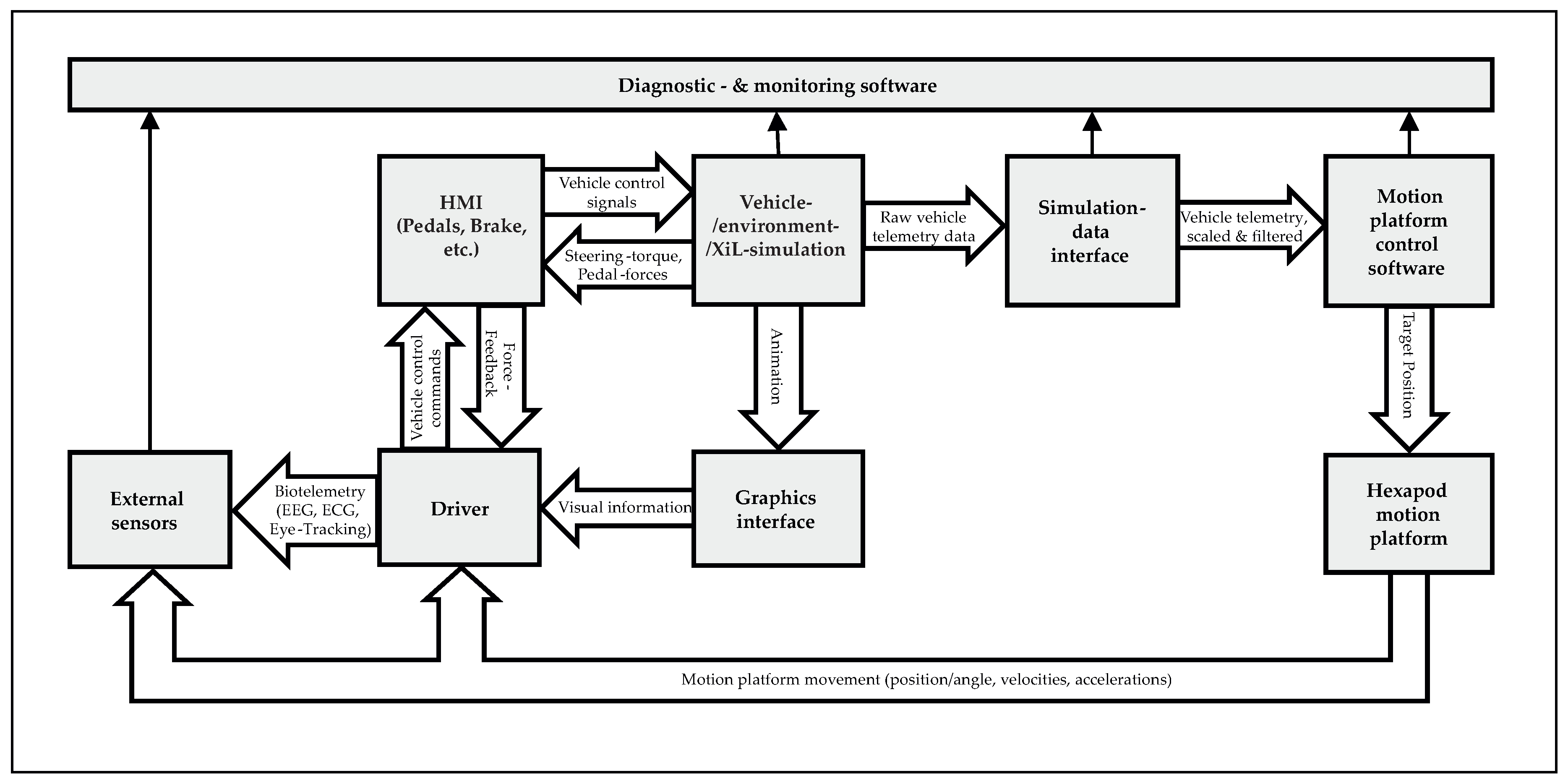
Figure 2.
Simulink implementation of the Driving Simulator Operation Environment. The human-machine interface signal-processing subsystem consists of (1): gear shifter signal subsystem, (2): pedal signal subsystem, (3): steering wheel signal subsystem. Further subsystems: (4): vehicle-/environment simulation subsystem, (5): simulation data interface subsystem, (6): internal sensor subsystem, (7): external sensor subsystem
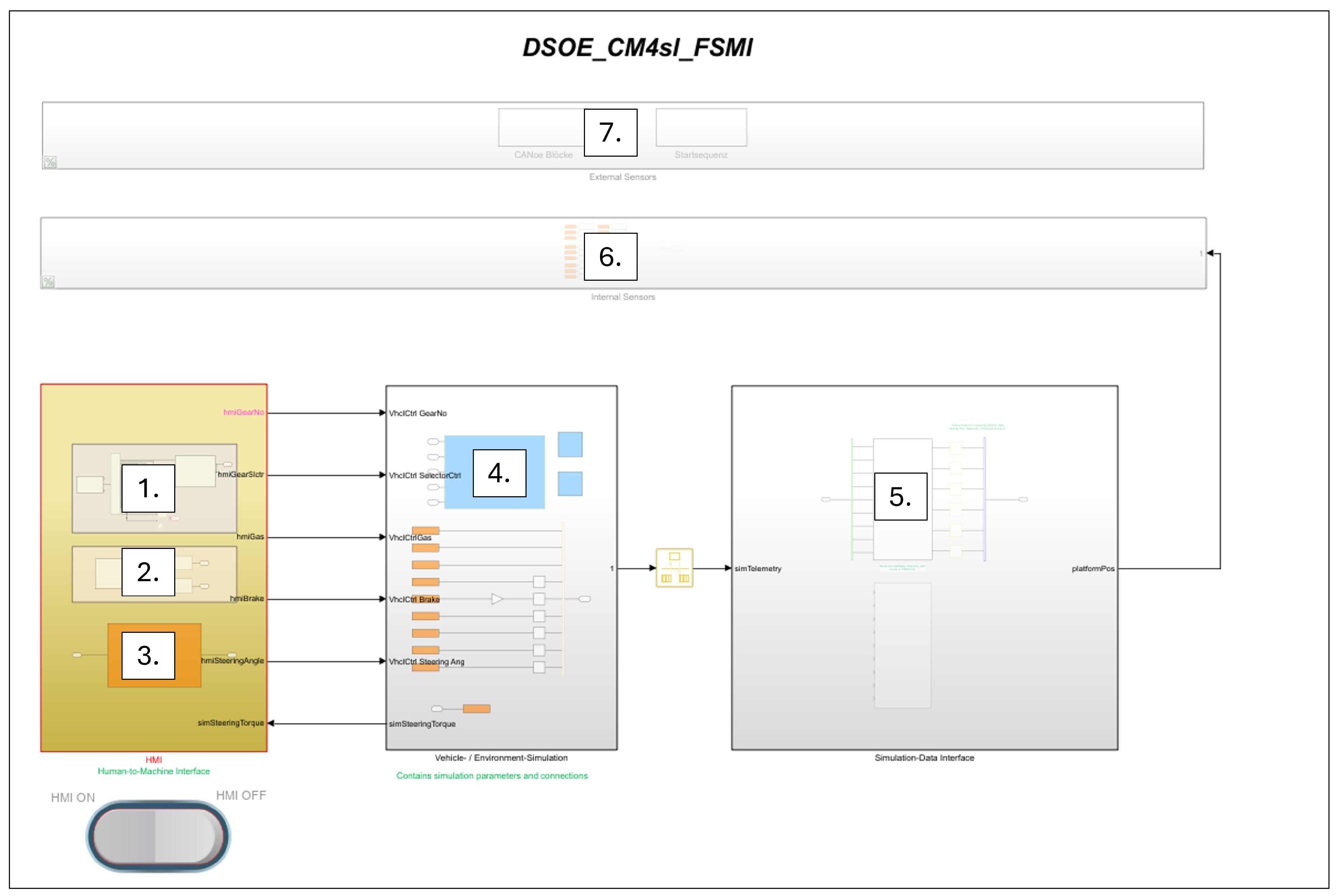
Figure 3.
Longitudinal and lateral dynamic workspace benchmark. The motion platforms can replicate acceleration combinations below each line, with platforms like the PS-6TL-800 (blue) highlighting above-average performance.
Figure 3.
Longitudinal and lateral dynamic workspace benchmark. The motion platforms can replicate acceleration combinations below each line, with platforms like the PS-6TL-800 (blue) highlighting above-average performance.
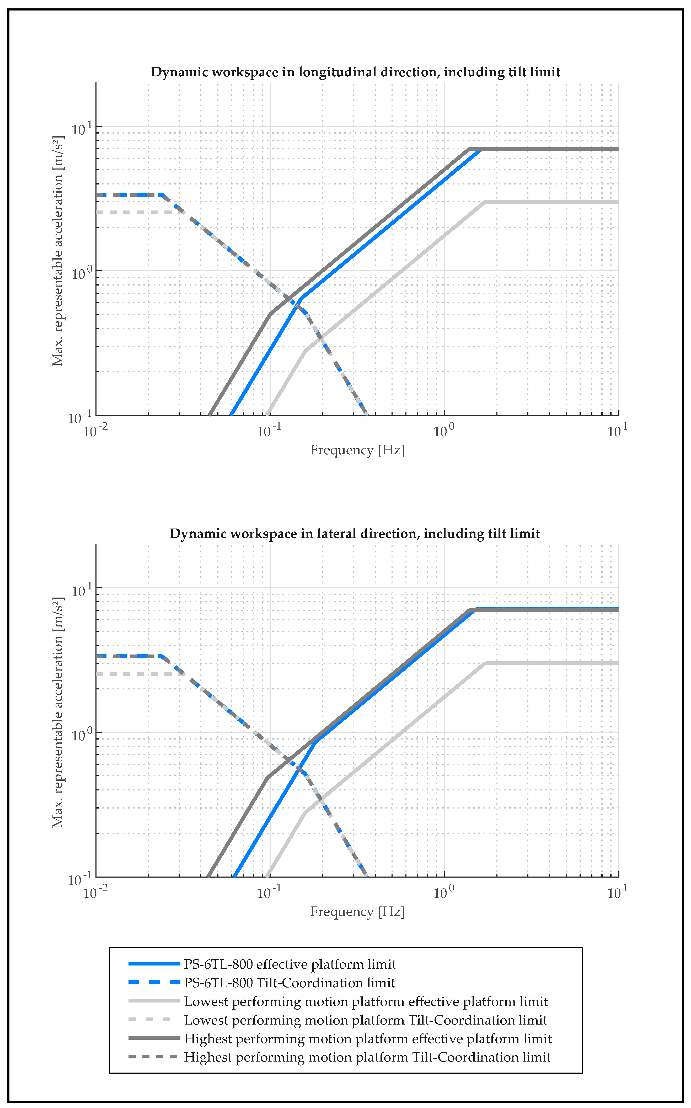
Figure 4.
Benchmark results for rotational dynamic workspaces. Out of 20 motion platforms examined, nine were selected for benchmarking. With rotational velocities up to 65 /s and accelerations up to 800 /s2, the PS-6TL-800 motion platform surpasses average values of 44 /s and 568 /s2
Figure 4.
Benchmark results for rotational dynamic workspaces. Out of 20 motion platforms examined, nine were selected for benchmarking. With rotational velocities up to 65 /s and accelerations up to 800 /s2, the PS-6TL-800 motion platform surpasses average values of 44 /s and 568 /s2
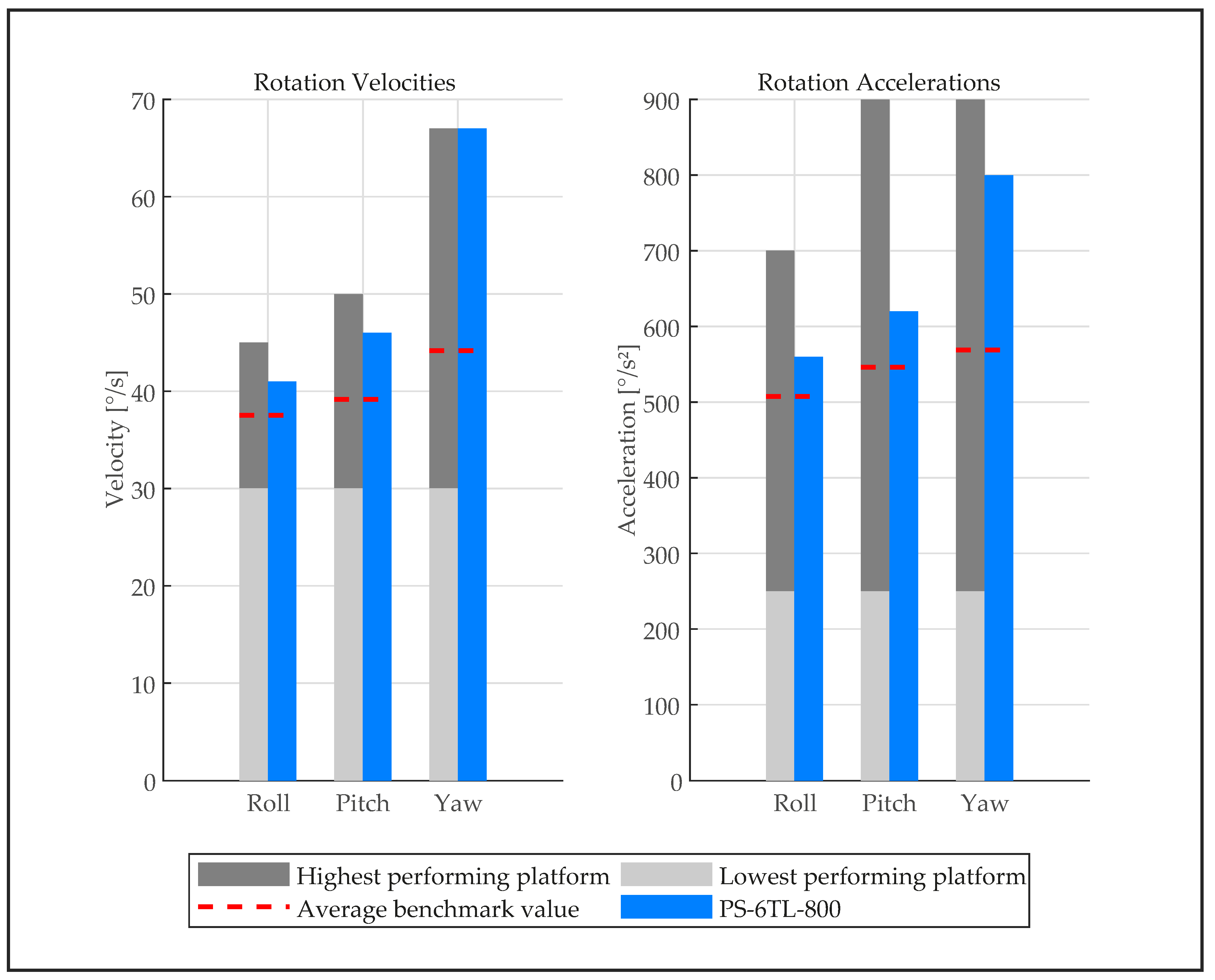
Figure 5.
Vehicle disassembly and preparation. The vehicle is cut behind the B-pillar and sealed off to maintain structural stiffness.
Figure 5.
Vehicle disassembly and preparation. The vehicle is cut behind the B-pillar and sealed off to maintain structural stiffness.
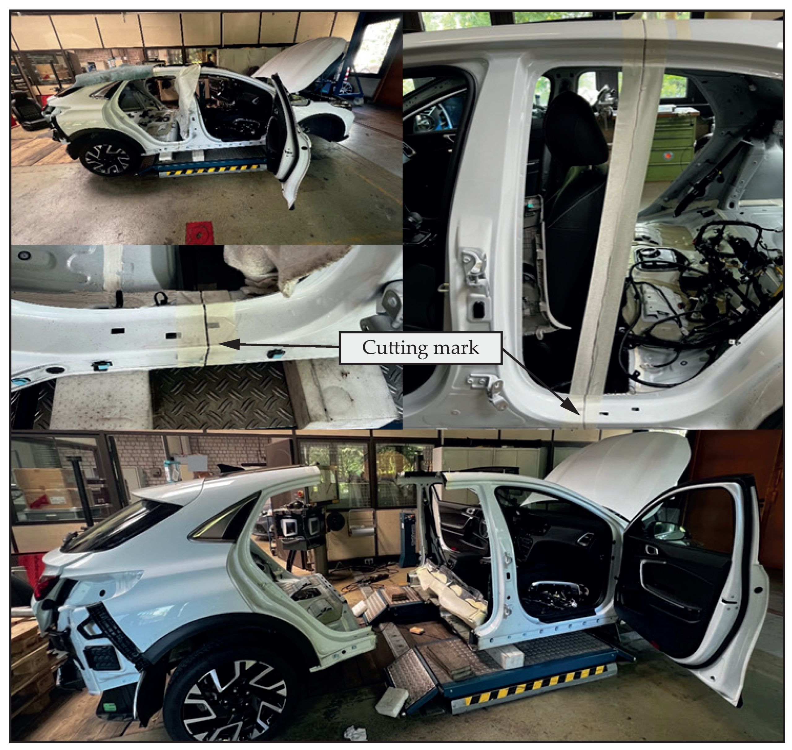
Figure 6.
Schematic overview of vehicle human-machine inteface components that are integrated into the Driver-in-the-Loop simulator.
Figure 6.
Schematic overview of vehicle human-machine inteface components that are integrated into the Driver-in-the-Loop simulator.
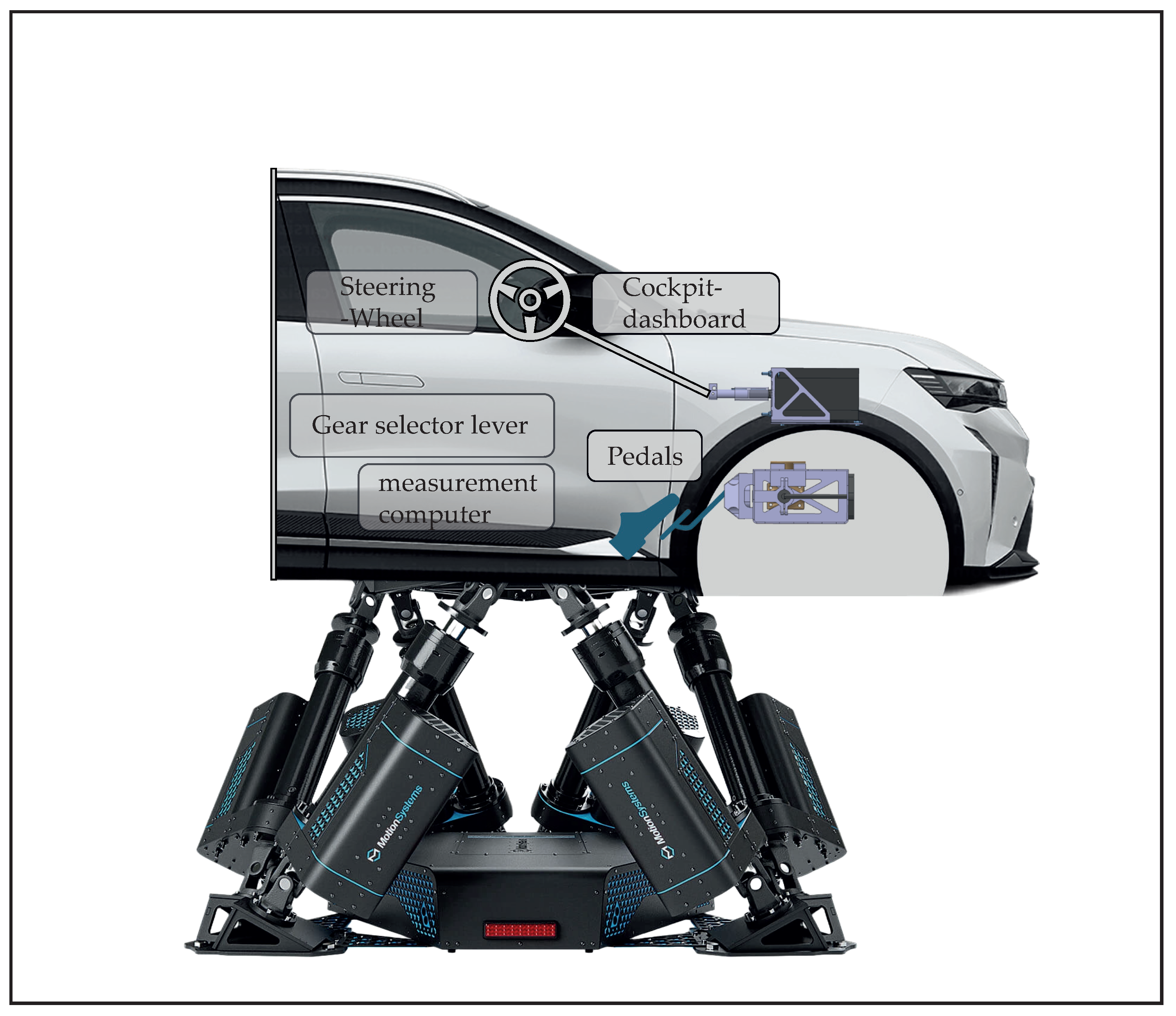
Figure 7.
Human-machine inteface signal processing architecture. The actuator/sensor signals are processed by a microcomputer and sent to the operating PC using a HID interface.
Figure 7.
Human-machine inteface signal processing architecture. The actuator/sensor signals are processed by a microcomputer and sent to the operating PC using a HID interface.
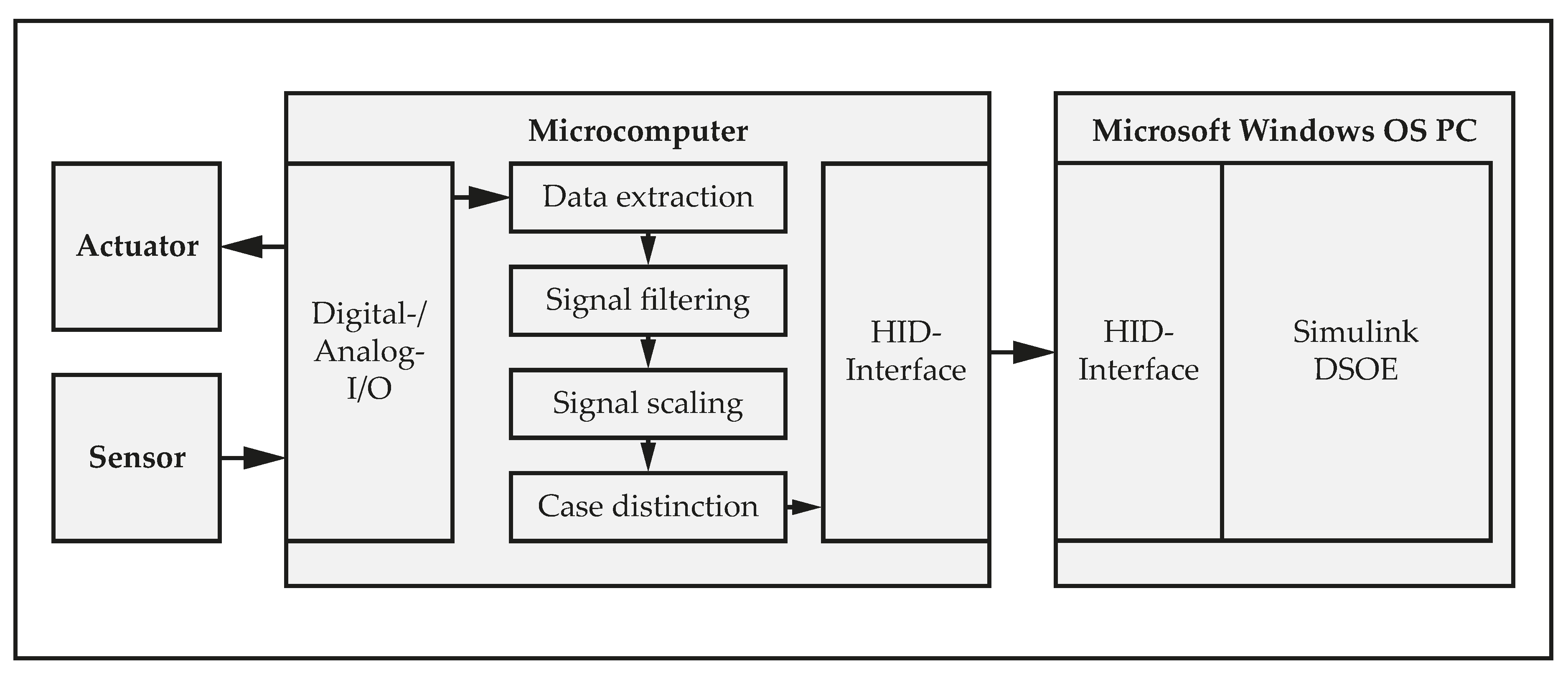
Figure 8.
Schematic of brake pedal hardware. (1): brake cylinders, (2): balance bar, (3): brake balance adjuster, (4): push rod, (5): secondary cylinder, (6): spring elements, (7): pressure sensor.
Figure 8.
Schematic of brake pedal hardware. (1): brake cylinders, (2): balance bar, (3): brake balance adjuster, (4): push rod, (5): secondary cylinder, (6): spring elements, (7): pressure sensor.
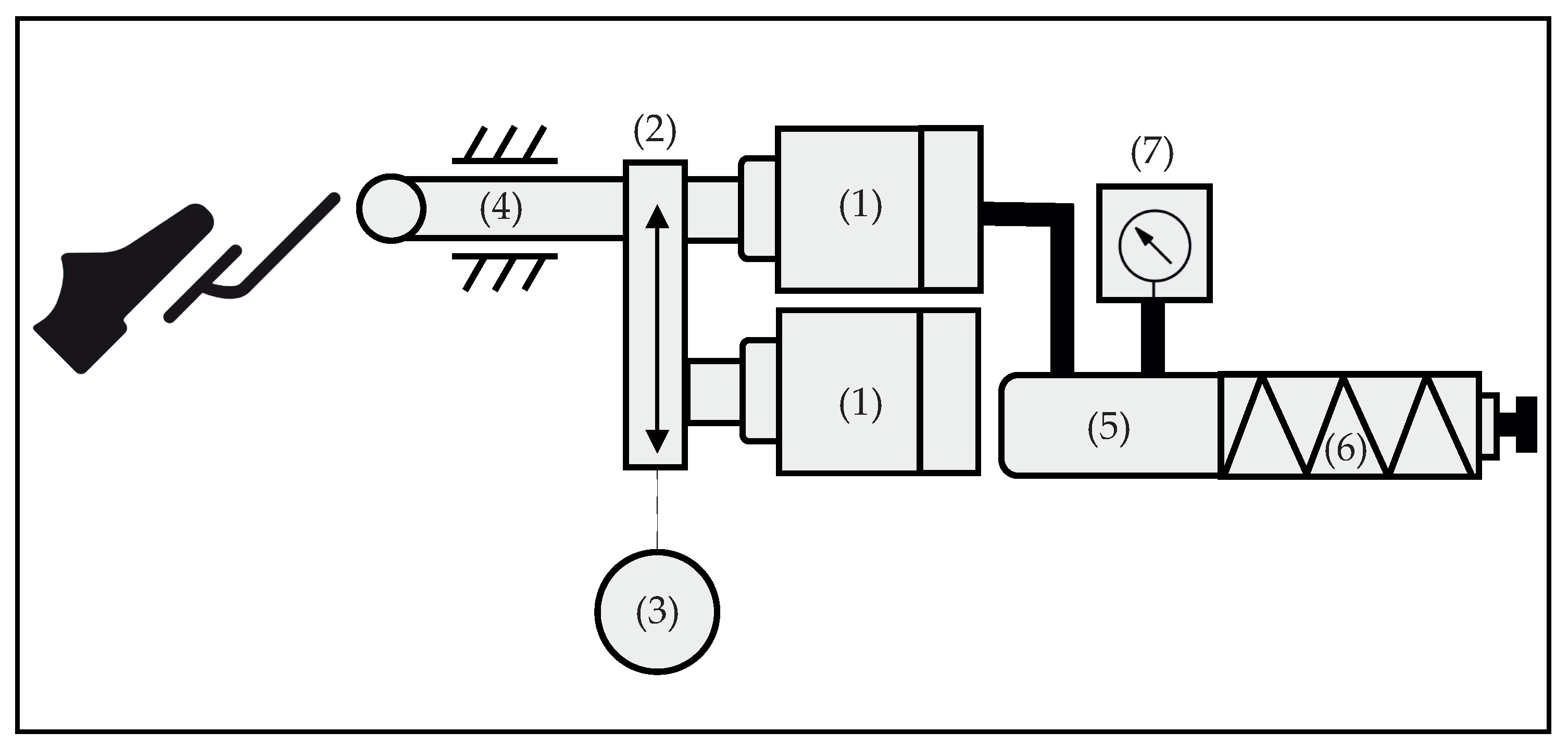
Figure 10.
Overview of steering system components. (1): encoder, (2): controller, (3): encoder cables, (4): USB connection cable, (5): power supply cable, (6): vehicle steering column, (7): vehicle steering wheel.
Figure 10.
Overview of steering system components. (1): encoder, (2): controller, (3): encoder cables, (4): USB connection cable, (5): power supply cable, (6): vehicle steering column, (7): vehicle steering wheel.
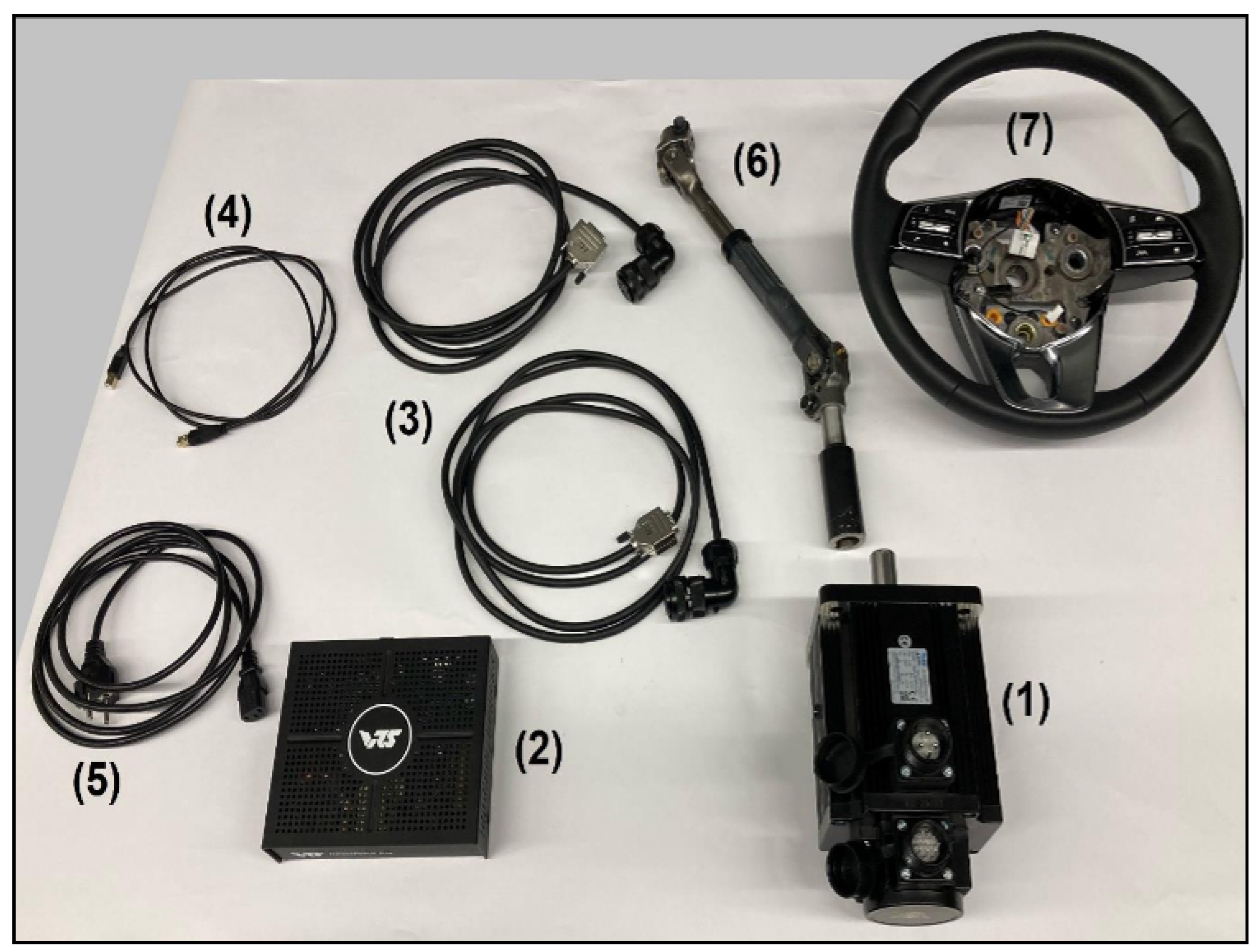
Figure 11.
Schematic: modification of the original gear-shifter. (1): gear-shifter lever, (2): push button switch, (3): linear potentiometer.
Figure 11.
Schematic: modification of the original gear-shifter. (1): gear-shifter lever, (2): push button switch, (3): linear potentiometer.
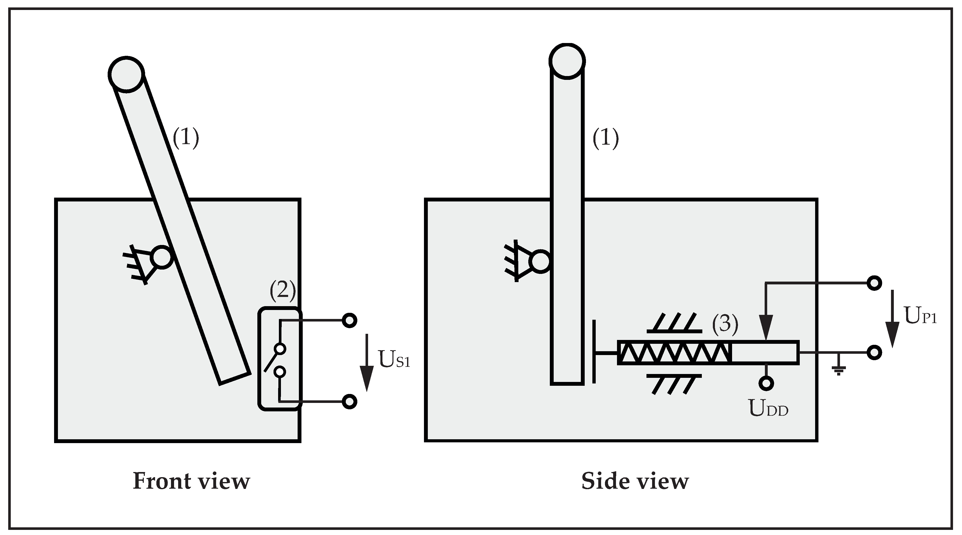
Figure 12.
Integration of the cockpit display into the driver’s cabin.
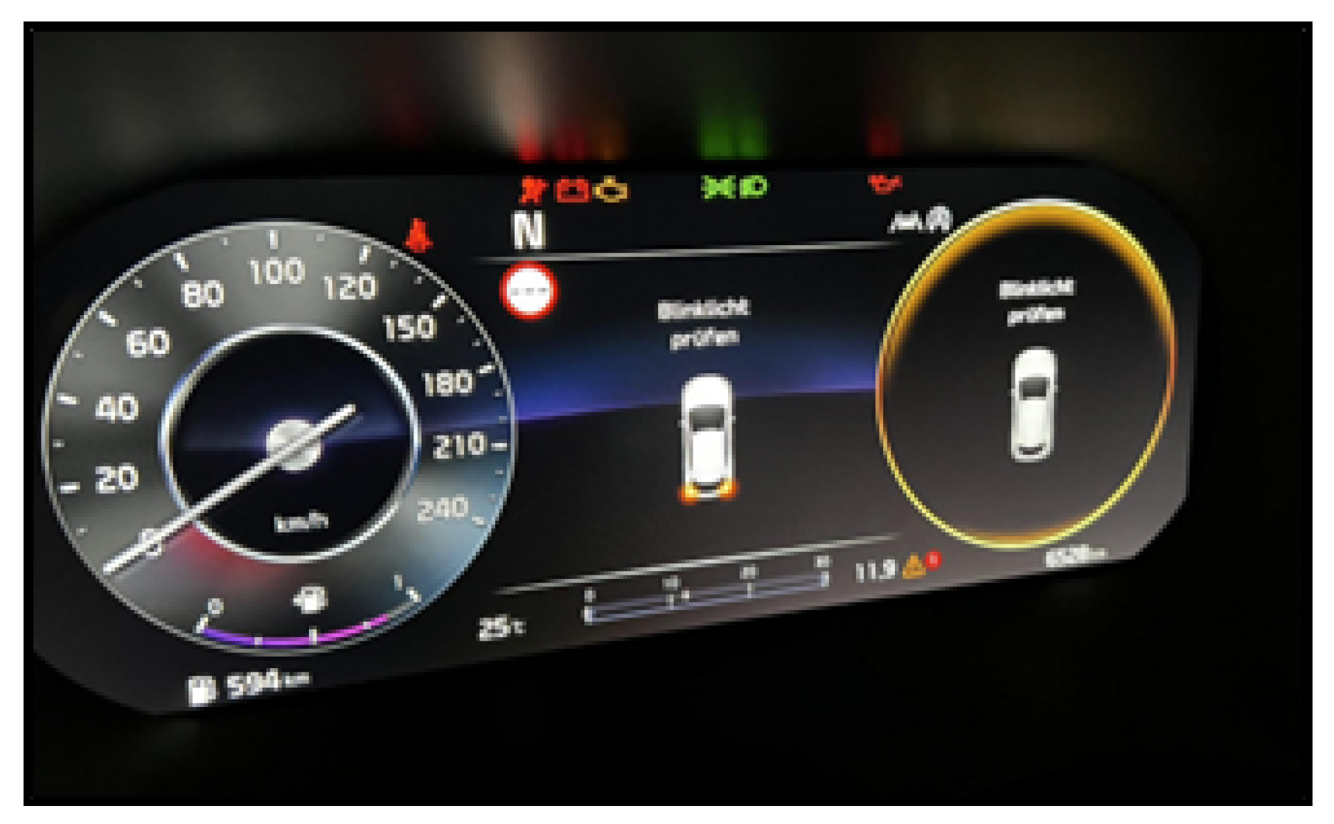
Figure 13.
Considerations and dependencies of the visual environment development.
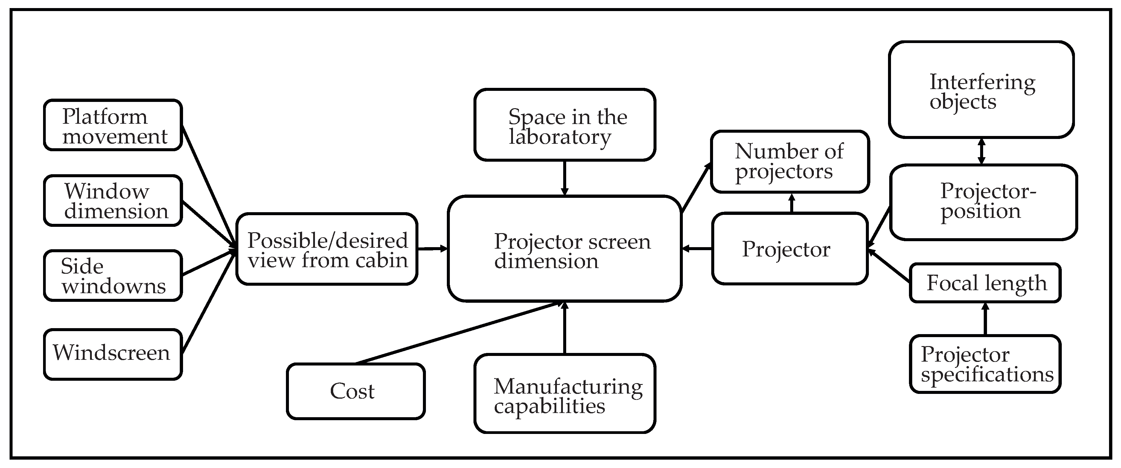
Figure 14.
Graphic analysis of available field of view depending on given angular motion platform movements. (1): projector screen, (2): vehicle cabin and motion platform.
Figure 14.
Graphic analysis of available field of view depending on given angular motion platform movements. (1): projector screen, (2): vehicle cabin and motion platform.
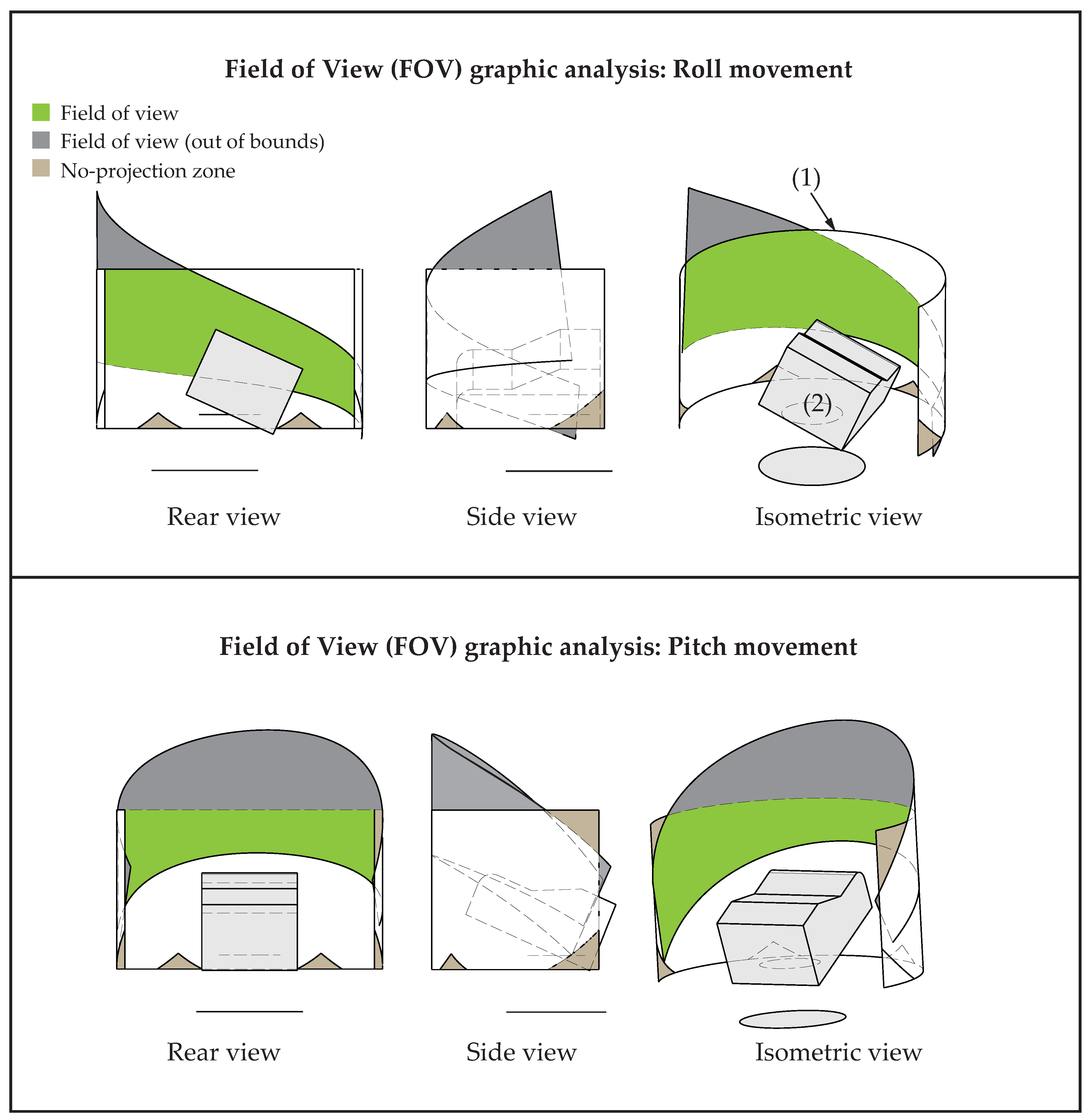
Figure 15.
The graphical analysis of available field of view (FOV) depending on shadow casting objects shows small casted shadows at the bottom of the screen by the projector beam’s crossing with the driver’s cabin. They are considered non-critical since they are not interfering with the FOV and therefore out of sight. (1): side projector beam, (2): front projector beam, (3): projector screen, (4) vehicle cabin and motion platform.
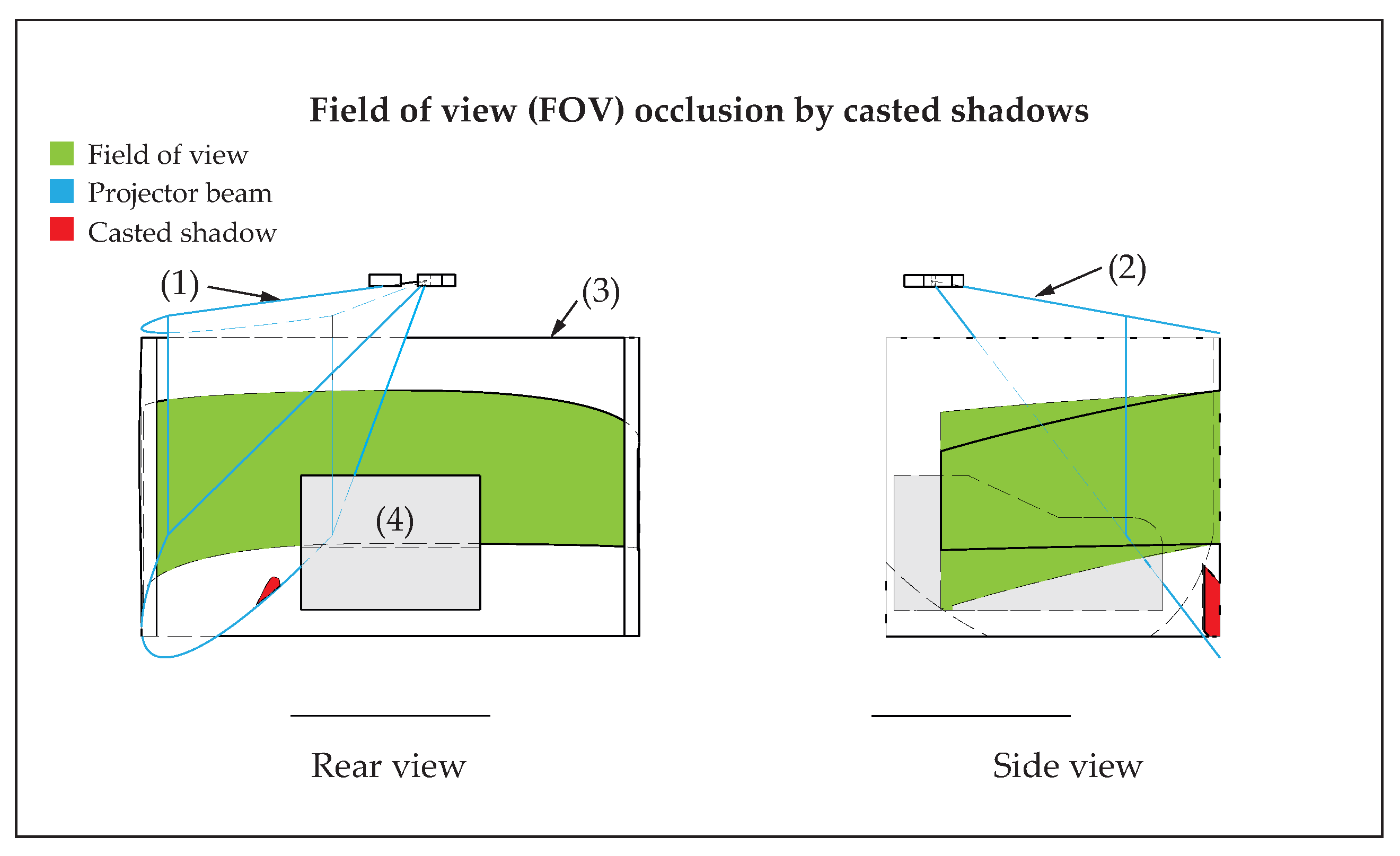
Figure 16.
Panoramic photo of cockpit view on the visual environment.
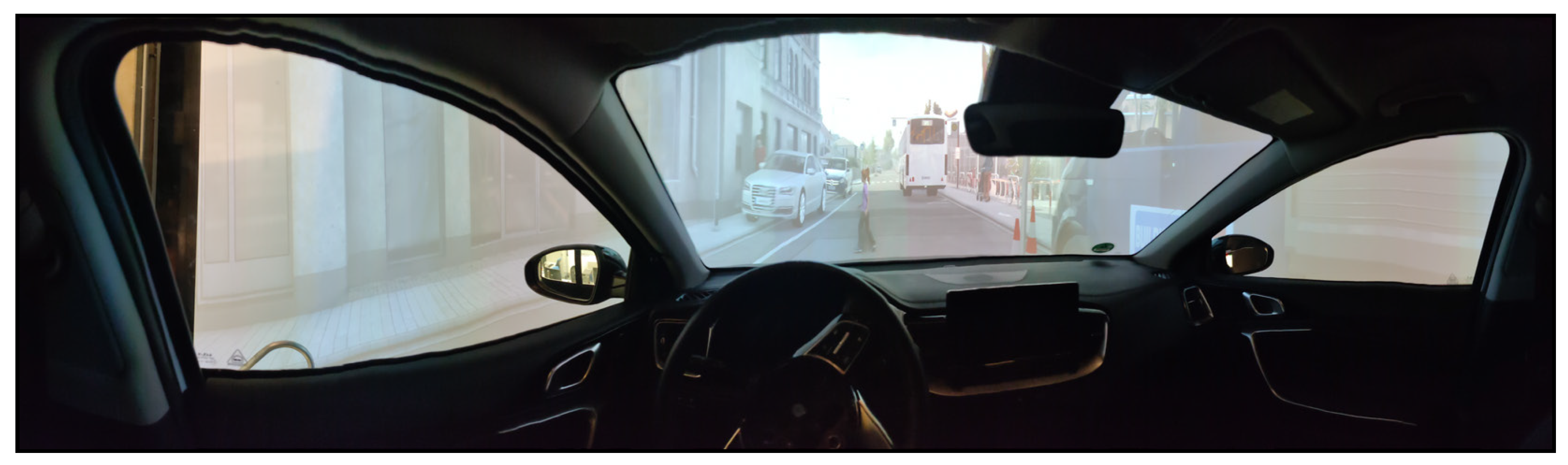
Figure 17.
Sway movement results of simulated lane change maneuver.
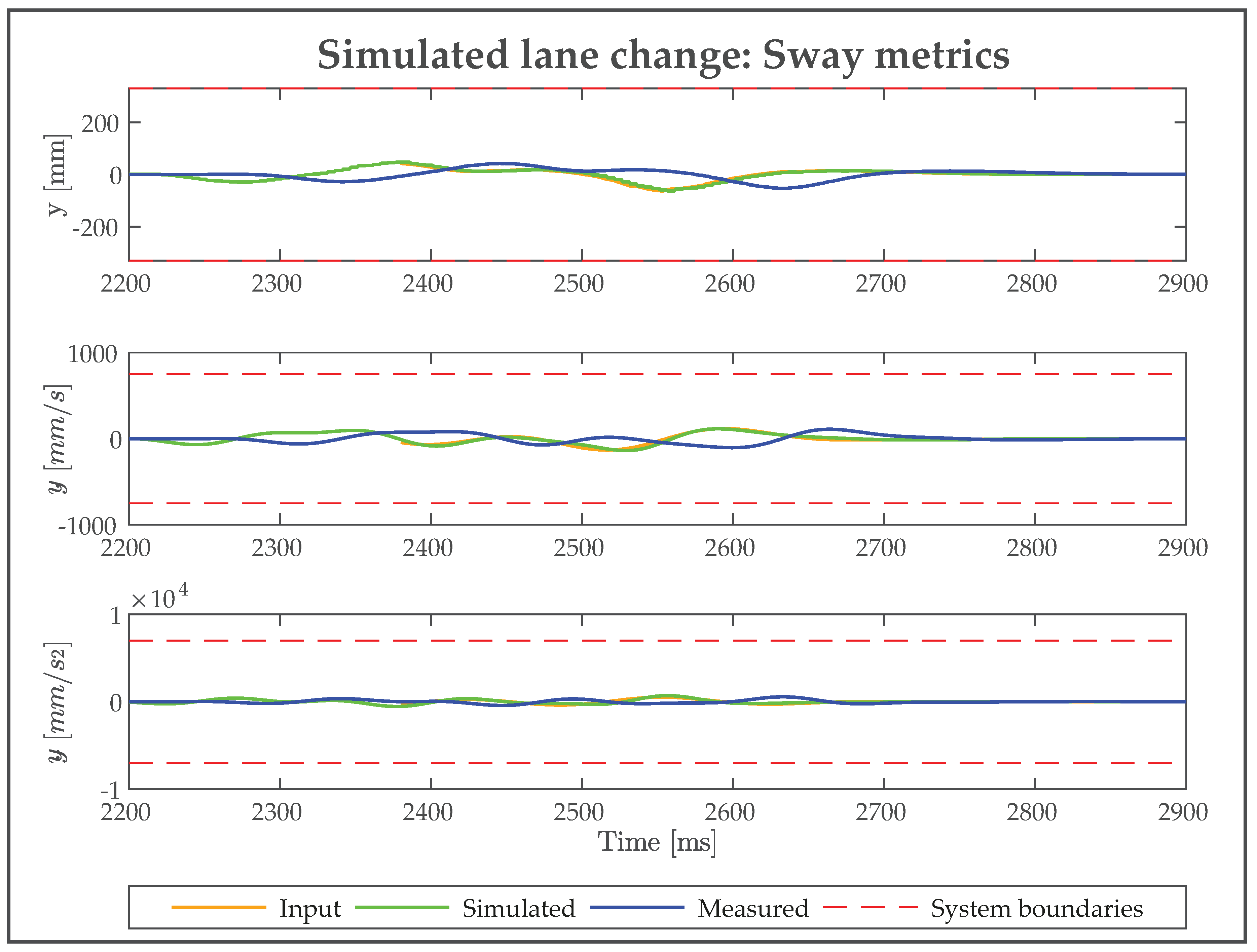
Figure 18.
Roll movement results of simulated lane change maneuver.
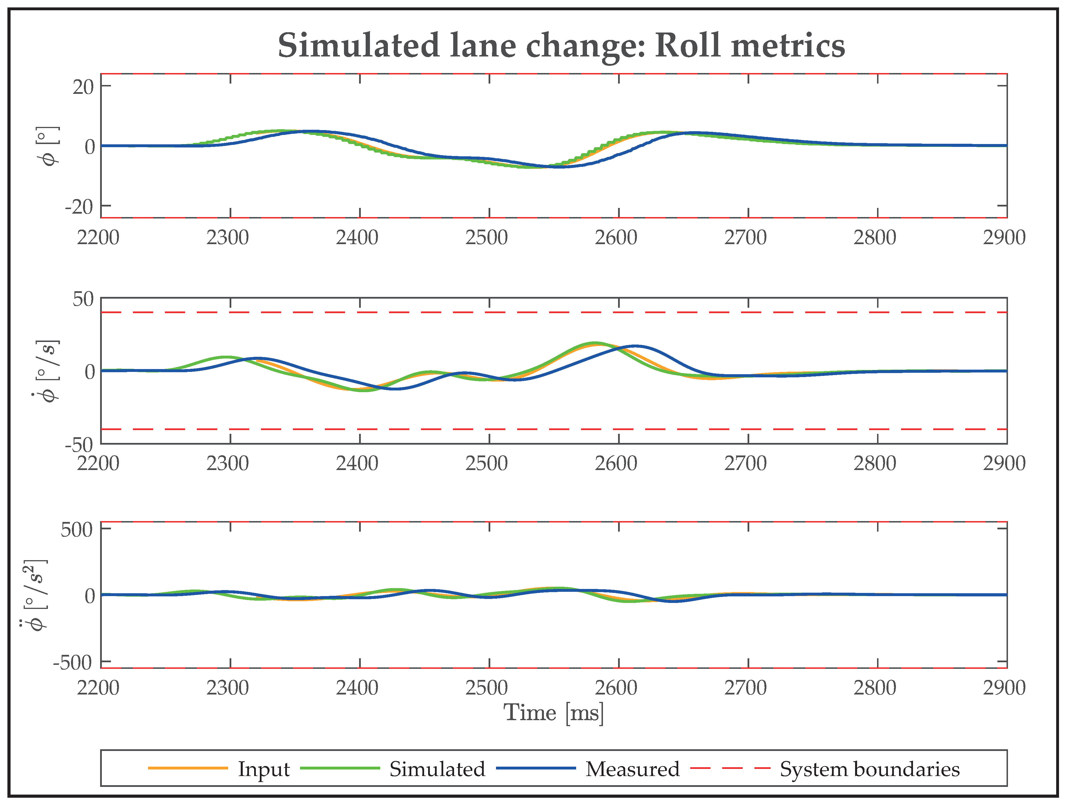
Figure 19.
Yaw movement results of simulated lane change maneuver.
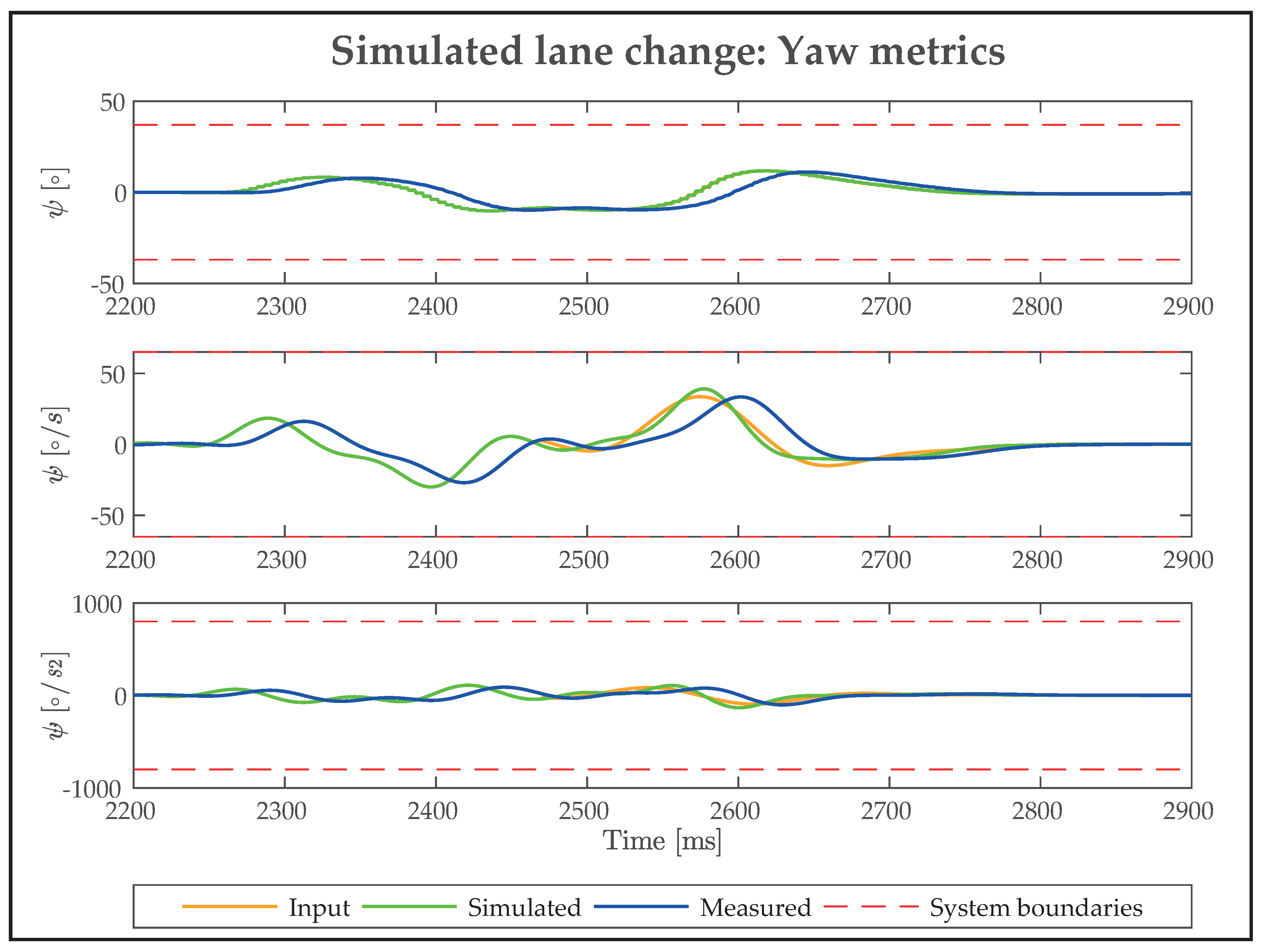
Table 1.
Field of view (FOV) loss analysis.
| Motion | Start angle FOV-loss [] | Max. angle motion platform [] | Max. FOV-loss [m2] | Eff. FOV surface [m2] | Rel. FOV-loss [%] |
|---|---|---|---|---|---|
| Roll | 11.2 | 24.5 | 2.3 | 21.15 | 11 |
| Pitch | 8.1 | 23.6 | 7.47 | 21.15 | 35 |
| Yaw | 12.2 | 37 | 1.81 | 21.15 | 9 |
Disclaimer/Publisher’s Note: The statements, opinions and data contained in all publications are solely those of the individual author(s) and contributor(s) and not of MDPI and/or the editor(s). MDPI and/or the editor(s) disclaim responsibility for any injury to people or property resulting from any ideas, methods, instructions or products referred to in the content. |
© 2025 by the authors. Licensee MDPI, Basel, Switzerland. This article is an open access article distributed under the terms and conditions of the Creative Commons Attribution (CC BY) license (http://creativecommons.org/licenses/by/4.0/).
Copyright: This open access article is published under a Creative Commons CC BY 4.0 license, which permit the free download, distribution, and reuse, provided that the author and preprint are cited in any reuse.


