
Submitted:
20 June 2025
Posted:
24 June 2025
You are already at the latest version
Abstract
This paper presents the design and water-surface motion analysis of an amphibious spherical robot equipped with a dual-propulsion system (ASR-DPS). Owing to its unique spherical geometry, the robot exhibits significantly different hydrodynamic behavior from conventional vessels. A comparative analysis of the frontal wetted area is conducted, followed by computational fluid dynamics (CFD) simulations to evaluate its water-surface motion characteristics. Results reveal that the hemispherical front increases hydrodynamic resistance and induces large-scale vortex structures due to intensified flow separation. Despite the higher resistance relative to traditional hulls, the robot’s deeper draft and dual propulsion configuration offer enhanced stability and improved maneuverability during surface operations. To validate its performance in real-world conditions, standard maneuvering experiments, including the circle test and zig-zag test, are conducted to assess the effectiveness of the propeller propulsion system. In addition, experiments are conducted to evaluate the water-surface motion performance of the pendulum propulsion system. A four-degree-of-freedom kinematic and dynamic model is developed to describe the robot’s water-surface motion. To handle model uncertainties and external disturbances, two control strategies are proposed: one based on model simplification and the other on adaptive control. Both strategies aim to regulate surge velocity and yaw angle. Simulation results are presented to compare the control performance of the proposed methods.
Keywords:
amphibious spherical robot
; surface motion analysis
; hydrodynamic characteristics
; dual-propulsion system
; kinematic and dynamic modeling
1. Introduction
Amphibious robots have attracted widespread attention from researchers due to their unique advantages in multi-terrain operations. Depending on their specific application purposes, various amphibious robots exhibit significant differences in structural design, functional layout, and propulsion mechanisms. For example, Bong-Huan Jun et al. [1] developed a walking robot named CR200 for inspecting shipwrecks or scours and performing sub-seafloor tomography surveys in fast-flowing and turbid underwater environments. This robot employs a six-legged walking mechanism, enabling it to traverse both land and seabed while collecting and recording underwater data using onboard sensors. To collect subsurface liquid samples and assess water toxicity levels, Sandeep Dhull et al. [2] proposed a small spherical amphibious robot named Aquapod. This robot utilizes a unique rolling locomotion mechanism driven by interactions with the environment and is equipped with a fluid sampling unit for in-situ water sampling. In the domain of amphibious combat, researchers have also developed various amphibious robotic systems to operate autonomously in turbulent surf zones. These systems aim to perform tasks such as shallow-water mine clearance and the classification and mapping of potential underwater threats [3,4,5,6]. Spherical objects exhibit distinctive advantages during motion, such as low energy consumption and high mobility. Additionally, the spherical geometry offers the largest internal volume for a given surface area, making it a favorable shape for robotic applications. These features have led to widespread research on spherical robots. For instance, Guo et al. [7,8,9,10] proposed a turtle-inspired spherical robot that utilizes water-jet propulsion for underwater movement and transforms into a legged robot for terrestrial locomotion. Zhan et al. [11] designed a spherical robot equipped with auxiliary fins, which enables locomotion both on land and in water through the rotation of the spherical shell. Li et al. [12] introduced a spherical robot driven by a combination of flywheel, pendulum, and propeller systems. The propeller is used for underwater propulsion, while the pendulum allows for rolling motion on land or the seabed, and the flywheel provides attitude control. Jia et al. [13] presented a conceptual amphibious spherical robot, in which the main body is spherical and features two extendable arms with propellers mounted at their ends. During underwater operation, the arms rotate to a horizontal position, allowing the propellers to generate thrust; for land movement, the arms rotate vertically, enabling rolling locomotion.Muhammad Affan Arif et al. [14] proposed an amphibious spherical robot equipped with dual eccentric pendulums and a flywheel. The eccentric pendulums facilitate rolling motion, while the flywheel provides large instantaneous torque to overcome obstacles.
While the aforementioned spherical robots exhibit notable advantages, most remain at the conceptual or laboratory prototype stage. To advance the practical application of spherical robots, this study proposes an innovative all-terrain, multi-environment amphibious spherical robot equipped with a dual-propulsion system, consisting of a pendulum propulsion system and a propeller propulsion system. The main contributions of this paper are as follows:
1) A novel amphibious spherical robot platform with dual propulsion systems is presented. The hydrodynamic characteristics of the robot on the water-surface are investigated, including stability analysis and a comparative study of the wetted surface area. Computational fluid dynamics (CFD) simulations are conducted to analyze the water-surface motion, and the results are compared with those of conventional ships. To the best of our knowledge, this is the first detailed comparative analysis between a spherical amphibious robot and traditional vessels in terms of water-surface dynamics.
2) The water-surface locomotion characteristics of the robot under propeller propulsion are experimentally evaluated using standard marine maneuvering tests, including the circle test and zig-zag test. Additionally, the performance of the pendulum propulsion system is also examined through controlled experiments.
3) A four-degree-of-freedom (4-DOF) kinematic and dynamic model of the robot’s water-surface motion is established to describe its behavior more precisely.
4) Based on the derived dynamic model, a control system is developed using sliding mode control (SMC). To address model uncertainties and environmental disturbances, two control strategies are proposed: a simplified model-based controller and an adaptive controller. Their performances are compared and analyzed through simulations.
The remainder of this paper is organized as follows: Section 2 introduces the overall design of the amphibious spherical robot and analyzes its hydrodynamic behavior on the water surface. Section 3 establishes a four-degree-of-freedom (4-DOF) kinematic and dynamic model for its water-surface motion. In Section 4, experimental analyses are conducted to evaluate the motion characteristics of the robot under different propulsion systems. Section 5 presents the design of a sliding mode controller and compares two control strategies to address model uncertainties. Simulation results validating the control performance are provided in Section 6. Finally, conclusions are drawn in Section 7.
2. Overall Design and Water Surface Locomotion Characteristics
2.1. Overall Design
The proposed amphibious spherical robot consists of three primary structural components: the spherical shell, the main internal frame, and the mounting platforms, as illustrated in Figure 1. The shell adopts a truncated-sphere geometry, providing a relatively large internal volume. The main frame is rotatably connected to the shell via a rotating shaft, enabling internal actuation. The control units, electrical modules, and various sensing components are housed within the main frame. A pendulum propulsion system is mounted at the lower part of the main frame, which allows the pendulum to swing in both pitch and roll directions, thereby changing the orientation and motion of the robot. The detailed mechanical design of this system can be found in our previous work [15,16]. The robot includes two external mounting platforms symmetrically located on both sides of the spherical shell. These platforms are rigidly connected to the internal main frame and serve as carriers for external sensors and actuators. The proposed amphibious spherical robot is equipped with two independent propulsion systems: a propeller propulsion system and a pendulum propulsion system. The propellers are mounted on the external mounting platforms, with one located on each side. Together with the internal electrical and control modules housed in the main frame, these two thrusters constitute the propeller propulsion system. This system serves as the primary means of locomotion on the water-surface and is capable of achieving zero-radius turning via differential thrust. In addition to the propeller propulsion system, a pendulum propulsion system is also integrated. This system comprises an internal pendulum and its associated components. By adjusting the pendulum’s position, an eccentric torque is generated, which induces rotational motion of the outer shell, thereby enabling the robot to move.

Table 1.
Parameter list of ASR-DPS.
| Parameter | Value |
|---|---|
| Size | 800 × 844 × 800 (mm) |
| Draft(T) | 510 (mm) |
| Mass(m) | 165 (kg) |
| propulsion system | 2 units |
| Maximum Speed (on water-surface) | 1.2 (m/s) |
| Minimum Turning Radius (on water-surface) | 0 (m) |
| Beam overall (B) | 0.84 (m) |
| Length overall (L) | 0.8 (m) |
| Longitudinal center of gravity () | 0 (m) |
| Hydrodynamic damping coefficient () | 0.62 |
| Yaw moment of inertia () | 6.142 () |
| Linear Damping in Surge () | -38.468 |
| Quadratic drag coefficient in surge () | 199.14 |
2.2. Water Surface Locomotion Characteristics
2.2.1. Water Surface Locomotion Stability
Unlike conventional unmanned surface vehicles (USVs), the amphibious spherical robot features its propeller thrusters mounted laterally beneath its hull. Additionally, it incorporates an internal two-degree-of-freedom pendulum propulsion system, enabling active adjustment of the robot’s attitude. The lateral placement of the propellers facilitates differential thrust, allowing for zero-radius turning. The key advantage of the internal pendulum propulsion lies in its capability for continuous, real-time attitude control, preventing the robot from being passively subjected to environmental disturbances that could lead to uncontrollable attitude changes. Another significant advantage is the ability to overcome stranding through spherical rolling locomotion – a critical challenge typically insurmountable for traditional USVs.
However, a drawback arises during water-surface locomotion: a stable and reliable controller is essential to regulate the pendulum’s position. Without such control, the amphibious spherical robot is highly prone to capsizing to the left or right during water-surface motion, as illustrated in Figure 2(a) and (b). Our team has previously designed a robust controller to stabilize the robot’s attitude via the pendulum propulsion system and eliminate roll motion, as detailed in our prior work [15].
However, following the elimination of roll motion, the amphibious spherical robot behaves akin to a self-righting roly-poly toy when in water. Its center of gravity is located below the waterline. Furthermore, the inherent structural characteristics of the spherical robot result in a significantly larger wetted surface area compared to conventional USVs and a draft exceeding 60% of its overall height. This structure also exhibits greater symmetry relative to typical USVs. Consequently, the robot demonstrates superior stability when encountering wind and waves, as illustrated in Figure 2(c).
2.2.2. Water-Facing Surface and Hydrodynamic Resistance
As Figure 3 shows, during water-surface locomotion, the spherical robot exhibits a substantially different hydrodynamic profile compared to conventional vessels or unmanned surface vehicles (USVs). Its forward-facing geometry is characterized by a bluff, hemispherical leading surface rather than a streamlined pointed bow, resulting in a relatively large frontal cross-sectional area in the direction of motion. This non-streamlined shape induces greater form and pressure drag, which dominate the total resistance, particularly at moderate to high speeds, contrasting with the friction-dominated resistance observed in slender hull designs. The resistance formula is[17]:
where is the hydrodynamic damping coefficient, denotes the fluid density, A denotes the submerged cross-sectional area, and u is the surge velocity.
According to this formula, under identical conditions, a larger submerged cross-sectional area A leads to greater hydrodynamic resistance. The amphibious spherical robot exhibits significantly higher hydrodynamic resistance during water-surface locomotion compared with conventional vessels, primarily due to two structural factors: its circular cross-section and a draft-to-height ratio exceeding 60%.
2.2.3. CFD Simulation Analysis of Water-Surface Motion
During water-surface locomotion, the amphibious spherical robot exhibits distinct hydrodynamic characteristics compared to conventional marine vessels. This difference stems primarily from its forward wetted surface, which features a spherical cap structure with significant curvature. This geometry results in a larger cross-sectional area in the direction of water ingress (flow direction). Consequently, the robot demonstrates marked differences in fluid flow characteristics around the body, hydrodynamic resistance distribution, and lift generation mechanisms relative to traditional vessels. To quantitatively assess and visually represent these disparities, we performed Computational Fluid Dynamics (CFD) simulations of the amphibious spherical robot’s water-surface motion using the commercial software STAR-CCM+ [18,19]. The computational setup mirrored that employed in a published STAR-CCM+ benchmark case study for a conventional vessel navigating at comparable speeds[20]. A comparative analysis of the simulation results, highlighting the key hydrodynamic differences, is presented in Figure 4.
As shown in Figure 4(a), the simulated free surface profiles indicate the formation of distinct bow and stern wave crests for both the amphibious spherical robot and the conventional ship. However, it is evident that the wave crest generated at the bow of the spherical robot exhibits a significantly wider spread compared to that of the ship. Moreover, the highest point of the bow wave in the case of the spherical robot is located directly in front of the robot, whereas for the ship, the wave crests reach their maximum height along the port and starboard sides near the bow. This discrepancy arises from the difference in hull geometry: the spherical robot features a dome-shaped frontal surface that causes oncoming flow to accumulate at the front, whereas the V-shaped bow of the ship facilitates lateral flow separation, diverting water to both sides. Furthermore, the free surface displacement pattern induced by the spherical robot appears more irregular and lacks a well-defined structure, in contrast to the triangular and more orderly wave pattern observed in the ship’s case.
In Figure 4(b), the vorticity plot clearly illustrates the motion of the spherical robot, with significant vortex formation surrounding the entire surface, particularly at the robot’s bow. A large C-shaped high-vorticity vortex forms along the leading edge, adhering closely to the wetted surface. The highest vorticity is observed on both sides and at the stern, where large-scale flow separation occurs, generating a persistent, high-intensity vortex structure encircling the central region. This is likely due to the sharp curvature and symmetry of the spherical robot, which causes the fluid to separate violently almost immediately upon encountering the sphere, forming a strong vortex ring around the rear. These turbulent vortices increase the hydrodynamic drag and energy dissipation of the spherical robot during its movement on the water-surface. In contrast, the vorticity plot of the ship hull shows that vortex structures are mainly concentrated around the bow, with the streamlined design of the hull delaying flow separation. This allows the fluid to stay attached to the surface for a longer distance, guiding the separation to a more controlled region. Consequently, vortices primarily form and shed at the bow and shoulders, resulting in smaller, more organized vortex structures with reduced intensity and influence. This design minimizes the turbulence in the wake, thus reducing energy loss and drag.
Similarly, the pressure distribution results in Figure 4(c) reveal that the spherical robot exhibits a region of locally elevated pressure in its near-wake region, aligning with characteristic bluff body drag behavior. Furthermore, the pressure distribution downstream appears highly disordered, indicative of significant turbulence and vortex shedding within the robot’s wake. In contrast, the vessel’s pressure distribution displays a gradual pressure decay radiating outwards from the hull, resulting in a relatively smooth distribution consistent with its streamlined form. The most striking feature is a distinct, organized striated pattern of high- and low-pressure regions extending orthogonally from the hull surface, perpendicular to its direction of travel.
Figure 4(d) presents the corresponding velocity distributions. It can be clearly seen that a distinct annular region of high-speed flow forms around the spherical robot, resulting from rapid flow separation from its surface. A wide and irregular wake region is also observed at the rear, characterized by varying flow velocities, indicating significant flow separation and turbulence in the wake of the spherical robot. Conversely, the velocity field around the vessel is overall smoother with lower localized gradients, reflecting the attached flow characteristic of a streamlined body.
3. Modeling of 4-DOF Kinematics and Dynamics
Generally, the amphibious spherical robot exhibits motion characterized by six degrees of freedom (6-DOF) during water-surface locomotion [21]. These DOFs comprise:
- Translational motion along three orthogonal axes (X, Y, Z).
- Rotational motion about these same axes, denoted by the Euler angles: roll (), pitch (), and yaw ().
Table 2.
The notation of SNAMME (1950) for marine vessels [21].
Table 2.
The notation of SNAMME (1950) for marine vessels [21].
| DOF | Force and moments | Linear and angular velocities | Positions and Euler angles |
|---|---|---|---|
| Motion in the x direction (surge) | X | u | x |
| Motion in the y direction (sway) | Y | v | y |
| Motion in the z direction (heave) | Z | w | z |
| Rotation about the x axis (roll) | K | p | |
| Rotation about the y axis (pitch) | M | q | |
| Rotation about the z axis (yaw) | N | r |
The specific definitions of these motions are illustrated in the Figure 5 Within the robot’s body-fixed coordinate frame, the origin is defined at the center of mass of the ASR-DPR.
Most USV studies employ a three-degree-of-freedom (3-DOF) dynamic model, justified by typical operating environments in calm inland waters or sheltered coastal areas where motion in the heave (z), roll (), and pitch () degrees of freedom is negligible. However, research addressing vessels operating in high sea states with significant wind and wave action often incorporates roll motion (), adopting a 4-DOF model to mitigate the critical risk of capsizing due to destabilizing roll moments. As previously established, the center of gravity (CG) of the amphibious spherical robot is dynamically coupled to its pendulum position. The pendulum’s capability for bi-directional actuation (surge-sway plane) renders the robot highly susceptible to roll excitation (). Consequently, this study develops a 4-DOF kinematic model encompassing surge (x), sway (y), roll (), and yaw () to capture the robot’s unique dynamics. The robot features two distinct propulsion systems: 1. Propeller Propulsion System: Fixed thrusters provide surge force (X) and yaw moment (N). 2. Pendulum Propulsion System: Generates surge force (X), roll moment (K), and yaw moment (N). In general, most USVs are modeled with 3 DOFs, namely surge, sway, and yaw. However, considering that the ASR-DPS’s pendulum propulsion system enables active control of the roll motion, a four-DOF kinematic and dynamic model is developed in this study.
3.1. Kinematic Model Derivation
The kinematic model of the ASR-DPS can be formulated as[21]:
where, , is the generalized velocity vector decomposed in the b-frame.
Thus, the kinematic model can be written as :
3.2. Dynamics Model Derivation
The Dynamics equations for surface navigation can be expressed as follows[21]:
The mass matrix is defined as , which includes both the rigid-body mass matrix of the robot () and the added mass matrix due to fluid interaction (). The Coriolis-centripetal matrix is given by , comprising the rigid-body Coriolis matrix () and the Coriolis matrix associated with the added mass (). The damping matrix is expressed as , where represents the linear damping component and represents the nonlinear damping. The vector denotes the restoring forces. The generalized force input is defined as , where refers to the thrust forces and moments generated by the propulsion system, and denotes the external environmental forces and moments. The 4-DOF model necessitates control inputs in surge, sway, roll, and yaw. However, the available actuators only provide three independent control channels, resulting in an underactuated control problem. The generalized control input vector is defined as:
It is also common to assume that the craft has homogeneous mass distribution and xz-plane symmetry so that . Let . Based on these definitions, the model can be further simplified and written in the following form:
3.3. Model Preprocessing
The dynamic model described above contains several uncertain components and external disturbances. To facilitate controller design, the known and unknown (uncertain and disturbance) terms are separated. The total uncertainty and disturbance terms are denoted by where, represent the total uncertainties associated with the surge, sway, roll, and yaw degrees of freedom, respectively. These terms include unmodeled dynamics, parameter uncertainties, and external disturbances. Some key hydrodynamic parameters are less affected by disturbances and can be estimated using empirical formulas available in the literature[15,22,23,24]. The retained parameters include: . The calculation formula is as shown in Table 3:
It is worth noting that, due to the highly symmetrical geometry of the spherical robot, it is reasonable to assume that . By defining the following mass and damping terms: , , , the system dynamics can be rewritten as the following equation:
4. Experimental Analysis of Motion Characteristics under Different Propulsion Systems
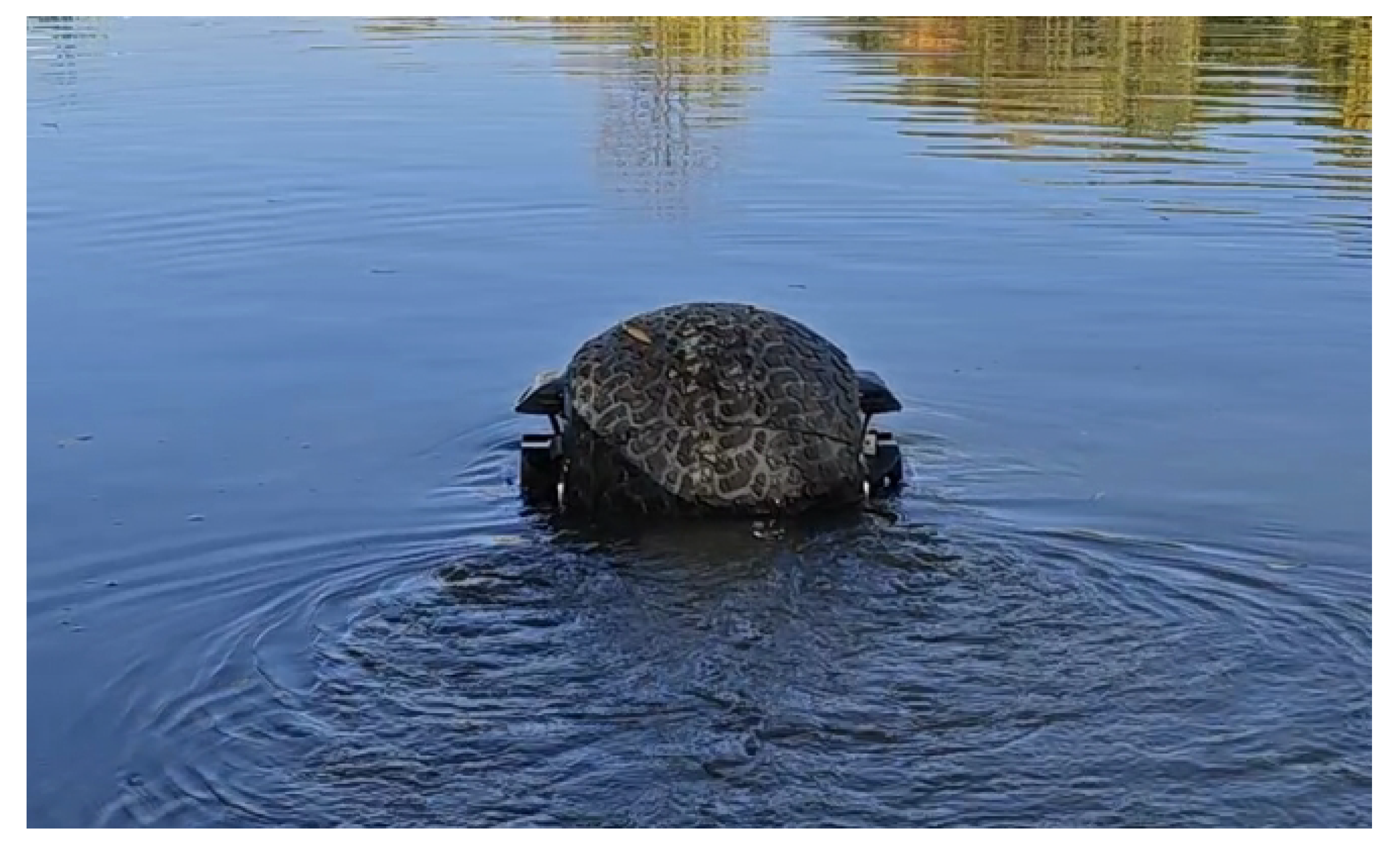
Based on the methodologies proposed in literature [12,25,26,27], this subsection presents an experimental analysis of the water-surface motion characteristics of the amphibious spherical robot. The water-surface mobility tests were conducted in Qizhen Lake on the Zijingang Campus of Zhejiang University. During the experiments, the wind and water current speeds were relatively low, and there were no disturbances from other vessels, indicating that the environmental interference in the lake was minimal.
Figure 6.
The amphibious spherical robot during water-based testing. (It is worth noting that the waterline appears to be slightly above the midpoint of the robot, indicating that more than half of the robot’s body is submerged.)
Figure 6.
The amphibious spherical robot during water-based testing. (It is worth noting that the waterline appears to be slightly above the midpoint of the robot, indicating that more than half of the robot’s body is submerged.)
4.1. Motion Characteristic Analysis under Propeller Propulsion System
To evaluate the maneuverability and dynamic response characteristics of the ASR-DPS, Zig-zag and Circle tests were selected as standard experimental protocols. These tests are widely adopted in both academic research and practical guidelines[p] (e.g., IMO standards) for assessing the hydrodynamic behavior and control performance of marine vehicles. The Zig-zag test provides insights into the yaw response, time delay, overshoot, and damping characteristics of the USV under abrupt steering inputs, making it particularly valuable for tuning and validating heading control algorithms. Meanwhile, the Circle test assesses the turning stability and steady-state turning behavior under constant rudder input, which is essential for identifying the system’s nonlinear maneuvering tendencies and verifying the existence of stable spiral motion. By combining these two complementary tests, a comprehensive understanding of the USV’s maneuvering behavior can be achieved, enabling robust controller design and reliable path-following performance in real-world conditions.
4.1.1. Circle Test
The circle test was conducted through two sets of experiments, as outlined in Table 4. Each experiment consisted of three sequential stages: an initial straight-line acceleration phase, followed by a constant-speed cruising phase, and finally a turning maneuver to assess the robot’s circular motion performance. In the course of the circle test, key dynamic parameters including the rotational speed, roll, pitch, and yaw angles, as well as the turning radius of the amphibious spherical robot, were recorded for analysis.
As shown in Figure 7a,b, when the propeller thrusters reach their maximum rotational speed, the amphibious spherical robot achieves a peak surge velocity of approximately 1.2 m/s. Notably, as soon as a differential in rotational speed is introduced between the left and right thrusters at the beginning of the circle test, the surge velocity drops rapidly to near zero. This indicates that the robot experiences significant hydrodynamic resistance during water-surface navigation — once propulsion support is lost, the velocity decays quickly (first test: 0.21 m/s2; second test: 0.147 m/s2). Meanwhile, the yaw rate increases sharply, reaching 0.43 rad/s in the first test and 0.33 rad/s in the second test. Figure 7c,d illustrate the evolution of roll and pitch angles during the circle test. A key observation is that the roll angle remains within 5° during both the acceleration and steady-state motion phases, with fluctuations constrained within ±2°. This suggests that the amphibious spherical robot maintains satisfactory roll stability during straight-line motion, validating the effectiveness of the implemented PID controller. However, during the circular maneuver phase, the roll angle suddenly increases from approximately 2° to 12°, resulting in a visibly tilted posture of the robot — a phenomenon also evident in the experimental photographs. This indicates a significant risk of lateral instability during sharp rotational maneuvers. One plausible explanation lies in the robot’s unique internal pendulum propulsion system, which allows motion in multiple directions. Despite having a dedicated roll control loop, the large differential torque generated by the side-mounted propellers during the turn can exceed the control authority of the system, leading to a temporary loss of roll stability. Once the propeller torque is removed, the roll angle quickly drops back to around 5°. Regarding the pitch angle, a sharp decrease is observed during the acceleration phase. This is attributed to the sudden thrust causing the pendulum mechanism to swing backward. Since the IMU is mounted on the central structural frame, it captures this backward motion, resulting in a rapid drop in pitch angle before it stabilizes. During the turning phase, the tilted motion of the spherical shell causes both the internal frame and the pendulum to incline, leading to an increase in pitch angle. The trajectory plot indicates that the thrusts generated by the left and right propellers are well balanced, enabling the robot to maintain a stable straight-line motion. The amphibious spherical robot demonstrates a zero turning radius, allowing for rapid in-place rotations. This highlights the high maneuverability and flexibility achieved by mounting propeller thrusters symmetrically on both sides of the robot.
4.1.2. Zig-zag Test
The experimental setup for the zig-zag test is detailed in Table 5.
Figure 8 presents the experimental data from the zig-zag test. Similarly, the zig-zag test reveals the motion characteristics of the amphibious spherical robot (ASR). In Figure 8a, the maximum surge speed is approximately 1.2 m/s, and the yaw rate at the half-maximum moment is 0.54 rad/s. The yaw rate curve clearly shows four sawtooth patterns, consistent with the standard zig-zag test variations. In Figure 8b, the variation in roll indicates that during the acceleration phase, the roll change is minimal, meaning the ASR maintained a flat locomotion. However, as the zig-zag test commenced, four cusp-like catastrophes occurred, indicating that the posture of the ASR tilted, which aligns with the observations from the circle test. The pitch angle variation is also consistent with the circle test results. Figure 8c shows the change in yaw during the test, where four rapid yaw variations are evident, indicating that the ASR-DPS performed quick rotations. From the results of the circle and zig-zag tests, it is clear that the ASR-DPS, due to its secondary power system (the pendulum propulsion system), experiences a disruption in posture stability under large rotational torques. However, once the large torque is removed, the ASR-DPS can quickly regain its stable posture. This also validates, from another perspective, that the pendulum propulsion system can flexibly alter the posture of the ASR-DPS to adapt to complex external environments—an advantage that conventional USVs lack. In Figure 8d, the shape of the trajectory matches the standard zig-zag test pattern. Both experiments further demonstrate that the ASR-DPS has agile movement capabilities on the water-surface, can rapidly respond to controller commands, and has the ability to actively adjust the roll angle.
4.2. Analysis of Motion Characteristics under the Pendulum Propulsion System
The pendulum propulsion system provides thrust by changing the position of the pendulum to generate an internal eccentric torque, which causes the spherical shell to roll. The rolling motion is naturally suitable for terrestrial locomotion. However, in fact, this rolling motion can also enable movement on the water-surface. Due to its inherent limitations, the motion speed on water is relatively low. In order to investigate the actual effect of using the pendulum propulsion system for water-surface movement in the proposed amphibious spherical robot, we conducted field tests.
Table 6.
Test Results of the Pendulum Propulsion System Performance.
| Throttle(%) | Velocity (m/s) | Energy(Wh) |
|---|---|---|
| 20 | 0.149 | 73.928 |
| 30 | 0.170 | 104.755 |
| 40 | 0.196 | 125.141 |
| 50 | 0.210 | 180.724 |
| 60 | 0.239 | 220.649 |
To analyze the water-surface locomotion characteristics of the pendulum propulsion system, we conducted five sets of experiments. As shown in the table, the motion speed of the amphibious spherical robot gradually increases with throttle input. However, even at 60% throttle, the maximum speed only reaches 0.239 m/s, which is significantly lower than the speed achieved using the propeller-based propulsion system. On the other hand, this propulsion method exhibits relatively low power consumption. This is primarily due to the reduced friction during rolling on the water-surface, resulting in lower energy usage. At the same time, this low-friction condition also contributes to the limited speed performance of the robot under this mode of operation.
As shown in Figure 9a, during water-surface locomotion powered by the pendulum propulsion system, a large volume of water is lifted off the surface by the rotation of the spherical shell. The resulting wake is notably different from the triangular track observed under propeller-based propulsion. Figure 9b illustrates the swinging motion of the internal pendulum during this mode of propulsion. Furthermore, by simultaneously actuating the pendulum to swing both forward-backward and left-right, the amphibious spherical robot is capable of executing a zero-radius turn on the water-surface. Unlike the differential-thrust-based zero-radius turn achieved by the twin propellers, the pendulum-driven zero-radius turn arises from the pendulum tilting to one side, which creates an asymmetry in the submerged surface area of the shell. This, combined with the eccentric torque generated by the pendulum, causes uneven hydrodynamic forces on either side of the sphere, resulting in a pivot-like rotation with essentially zero turning radius.
5. Controller Design
In Section 3, we established the kinematic and dynamic models of the amphibious spherical robot, and performed preliminary model preprocessing. In this section, we will design controllers for the amphibious spherical robot based on the established dynamic model. Regarding the four unknown disturbance terms in the model, , current research mainly addresses them in two ways. The first approach is to directly ignore these terms, since their effects are relatively small during normal motion in still water; thus, many scholars have neglected them [28,29,30]. Another approach is to design adaptive methods to compensate for these four terms [22,31,32]. Sliding mode control, known for its strong robustness against disturbances and time delays, has been widely used in water-surface motion control of USVs[22,28,29,30]. Therefore, this work implements both approaches for the design of sliding mode controllers and provides a comparative simulation analysis of their performance. Prior to controller design, several assumptions are made to ensure the validity of the control strategy:
- Assumption 1: The disturbances are bounded but unknown;
- Assumption 2: The ASR-DPS is modeled as a rigid body with symmetric geometry about both the longitudinal and lateral axes;
- Assumption 3: During controller design, the pendulum propulsion system is considered locked and inactive; thus, the center of mass of the ASR remains fixed;
- Assumption 4: The body-fixed coordinate system is established at the center of mass.
5.1. Sliding Mode Controller with Neglected Uncertainties and Disturbances(SMC-NUD)
When the robot operates at low speeds on calm, flat water, the model can be further simplified by omitting factors with negligible influence and disregarding environmental disturbances (i.e., ). The resulting simplified model is therefore given by:
Due to the weak coupling between the surge dynamics and the other degrees of freedom, the surge-direction dynamics can be decoupled from the overall model, yielding the following expression:
The sliding surface be defined as follows:
where the surge speed error is denoted as and the stands the desired speed, parameter . The reaching law of the sliding mode controller:
By differentiating Equation (11), we can obtain:
According to the transformation, we can obtain the surge speed sliding controller :
Similarly, a sliding mode controller for yaw rate can be obtained:
5.2. Adaptive Sliding Mode Controller(ASMC)
During the design of the adaptive sliding mode controller, we set the sliding surface as:
Adaptive convergence laws can be designed based on the literature [10,11].
where, denotes the self-adaptive gain coefficient, while signifies the constant gain coefficient. The specific self-adaptive gain coefficient is illustrated below:
where, the adjustment of enables the establishment of a work range for a specific model, designated as . This is accomplished by employing the tanh continuous law, which facilitates the realization of through the implementation of the double-sided curve at the specified boundary value, denoted as . This process ensures a seamless transition at the specified boundary value, .
After substituting into the dynamic Equation (8) and simplifying, the adaptive surge speed sliding mode controller can be obtained as:
The same method can lead to the adaptive sliding mode control law for yaw rate as follows:
6. Controller Simulation and Validation Analysis
To validate the performance of the aforementioned controller, we developed a Simulink simulation model on the MATLAB platform. We designed a figure-eight desired trajectory, and the actual trajectory was controlled by adjusting the surge speed and yaw rate.
6.1. Simulation Results of the SMC-NUD
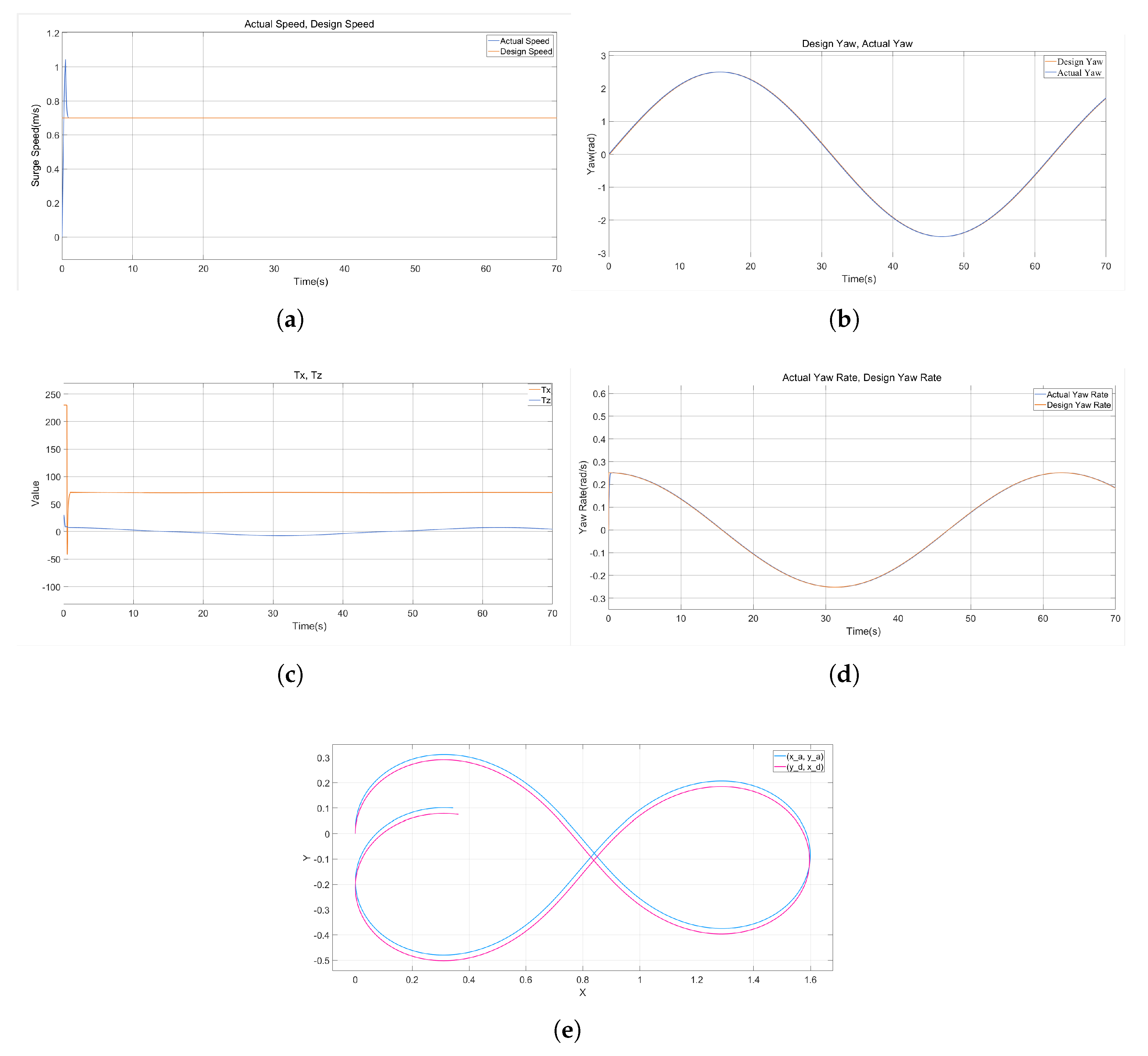
As shown in Figure 10, during surge speed tracking, the actual velocity exhibits minor fluctuations around the desired value. In contrast, the yaw angle tracking performance is excellent, with the actual trajectory closely matching the desired trajectory. Notably, while the yaw rate tracking curve generally coincides with its desired counterpart, two distinct transient spikes appear in the yaw rate response during abrupt reversals in turning direction (e.g., switching instantly from clockwise to counterclockwise, corresponding to sign changes in the torque command from positive to negative or vice versa). Concurrently, the torque command also undergoes abrupt step changes. Analysis of the control inputs and reveals a significant reduction in chattering. This demonstrates that the designed SMC-NUD performs robustly and effectively mitigates the inherent chattering issue associated with sliding mode control method.
6.2. Simulation Results of the ASMC
As illustrated in the figure, the tracking performance for surge speed, yaw angle, and yaw rate is consistently excellent, with both the desired and actual trajectories exhibiting close agreement. Concurrently, the control inputs and remain smooth, exhibiting significantly reduced chattering. Notably, the simulation results for the adaptive sliding mode control approach show no recurrence of the transient spikes in the yaw rate response. This indicates that the ASMC effectively handles transient yaw maneuvers without inducing abrupt changes in the torque command. Furthermore, a comparison of the trajectory tracking performance clearly demonstrates superior accuracy under ASMC compared to the SMC-NUD scheme. These results collectively validate the enhanced overall control performance achieved by ASMC.
Figure 11.
Simulation Results of the ASMC: (a)Surge Speed. (b)Yaw Angle. (c)Yaw Rate. (d)Control Inputs. (e)Trajectory Tracking.
Figure 11.
Simulation Results of the ASMC: (a)Surge Speed. (b)Yaw Angle. (c)Yaw Rate. (d)Control Inputs. (e)Trajectory Tracking.
7. Conclusions
This work presents the design and hydrodynamic analysis of an amphibious spherical robot featuring dual propulsion systems, with comprehensive structural and parametric specifications. Hydrodynamic evaluation grounded in naval architecture principles identified critical surface locomotion characteristics—including stability, wetted surface area, and hydrodynamic resistance—where computational fluid dynamics simulations further revealed distinct flow separation patterns and turbulent dissipation around the ASR-DSP configuration. These phenomena manifested as elevated wave resistance, pronounced vortex generation, and unfavorable pressure distributions that collectively increase motion drag. Experimental validation through zig-zag and circular maneuvers demonstrated inherent roll instability under high-torque inputs, frequently leading to capsizing, while the pendulum propulsion system exhibited fundamentally limited aquatic mobility characterized by insufficient thrust generation despite its lower energy consumption. To address dynamic uncertainties and environmental disturbances within the derived 4-DOF model, two control strategies were developed, including model simplification and adaptive sliding mode control. The simulation results confirm the superior performance of the adaptive sliding mode controller in achieving precise surge speed tracking, robust yaw regulation, and stable, chatter-free torque outputs, establishing its efficacy in hydrodynamically stabilizing unconventional amphibious platforms.
Author Contributions
Conceptualization, You Wang, Hongqun Zou and Guang Li; methodology, You Wang and Hongqun Zou; software, Fengqi Zhang, Meng Wang and Hongqun Zou; validation, Fengqi Zhang, Meng Wang and Hongqun Zou; data curation, Hongqun Zou; writing—original draft preparation, Hongqun Zou; writing—review and editing, You Wang and Hongqun Zou; funding acquisition, You Wang and Guang Li. All authors have read and agreed to the published version of the manuscript.
Funding
This work is supported by the State Key Laboratory of Industrial Control Technology, China (Grant No.ICT2024A21) and the Rotunbot (Hangzhou) Technology Co., Ltd fund.
Data Availability Statement
Dataset available on request from the authors.
Conflicts of Interest
The authors declare no conflicts of interest.
Abbreviations
The following abbreviations are used in this manuscript:
| ASR-DPS | Amphibious Spherical Robot equipped with a Dual-Propulsion System |
| CFD | Computational Fluid Dynamics |
| USVs | Unmanned Surface Vehicles |
| SMC-NUD | Sliding Mode Controller with Neglected Uncertainties and Disturbance |
| ASMC | Adaptive Sliding Mode controller |
References
- Jun, B.-H.; Shim, H.; Kim, B.; Park, J.-Y.; Baek, H.; Yoo, S. ; & Lee, P.-M. (2013). Development of seabed walking robot CR200. In Proc. 2013 MTS/IEEE OCEANS-Bergen. IEEE: Bergen, Norway; pp 1–5.
- Dhull, S.; Canelon, D.; Kottas, A.; Dancs, J.; Carlson, A. ; & Papanikolopoulos, N. (2012). Aquapod: A small amphibious robot with sampling capabilities. In Proc. 2012 IEEE/RSJ Int. Conf. Intell. Robot. Syst.. IEEE: Vilamoura-Algarve, Portugal; pp 100–105.
- Bernstein, C.; Connolly, M.; Gavrilash, M.; Kucik, D. ; & Threatt, S. (2001). Demonstration of surf zone crawlers: Results from auv fest 01. In Proc. Symp. Zombie Crab Gen.. Naval Surface Warfare Center: Panama City, FL.
- Prahacs, C.; Saudners, A.; Smith, M. K.; McMordie, D. ; & Buehler, M. (2004). Towards legged amphibious mobile robotics. In Proc. Can. Eng. Educ. Assoc.
- Harkins, R.; Ward, J.; Vaidyanathan, R.; Boxerbaum, A.; & Quinn, R. D. (2005). Design of an autonomous amphibious robot for surf zone operations: part II-hardware, control implementation and simulation. In Proc. 2005 IEEE/ASME Int. Conf. Adv. Intell. Mechatron.. IEEE: Monterey, CA, USA; pp 1465–1470.
- Boxerbaum, A. S.; Werk, P.; Quinn, R. D. ; & Vaidyanathan, R. (2005). Design of an autonomous amphibious robot for surf zone operation: part I mechanical design for multi-mode mobility. In Proc. 2005 IEEE/ASME Int. Conf. Adv. Intell. Mechatron.. IEEE: Monterey, CA, USA.
- Li, M.; Guo, S.; Hirata, H.; & Ishihara, H. (2015). Design and performance evaluation of an amphibious spherical robot. Robot. Auton. Syst., 64, 21–34.
- Guo, S.; Mao, S.; Shi, L. ; & Li, M. (2012). Design and kinematic analysis of an amphibious spherical robot. In Proc. 2012 IEEE Int. Conf. Mechatron. Autom.. IEEE: Chengdu, China; pp 2214–2219. [Google Scholar]
- Xing, H.; Shi, L.; Hou, X.; Liu, Y.; Hu, Y.; Xia, D.; Li, Z. ; & Guo, S. (2021). Design, modeling and control of a miniature bio-inspired amphibious spherical robot. Mechatronics, 77, 102574.
- Xing, H.; Guo, S.; Shi, L.; He, Y.; Su, S.; Chen, Z.; & Hou, X. (2018). Hybrid locomotion evaluation for a novel amphibious spherical robot. Appl. Sci., 8(2), 156.
- Chi, X.; & Zhan, Q. (2021). Design and modelling of an amphibious spherical robot attached with assistant fins. Appl. Sci., 11(9), 3739.
- Li, Y.; Yang, M.; Sun, H.; Liu, Z.; & Zhang, Y. (2018). A novel amphibious spherical robot equipped with flywheel, pendulum, and propeller. J. Intell. Robot. Syst., 89, 485–501.
- Jia, L.; Hu, Z.; Geng, L.; Yang, Y. ; & Wang, C. (2016). The concept design of a mobile amphibious spherical robot for underwater operation. In Proc. 2016 IEEE Int. Conf. Cyber Technol. Autom. Control Intell. Syst.. IEEE: Chengdu, China; pp 411–415.
- Arif, M. A.; Zhu, A.; Mao, H.; Zhou, X.; Song, J.; Tu, Y.; & Ma, P. (2023). Design of an amphibious spherical robot driven by twin eccentric pendulums with flywheel-based inertial stabilization. ISA Trans., 28(5), 2690–2702.
- Zou, H.; Wang, M.; Zhang, F.; Guan, X.; Liu, Y.; Wang, Y.; Luo, Z. ; & Li, G. (2025). Design of an amphibious spherical robot with roll auto-stabilisation and propulsion system auto-switching. Ships Offshore Struct., 1–13.
- Zou, H.; Lin, B.; Cao, X.; Zhang, F.; Zhang, Z.; & Wang, Y. (2023). Research on Amphibious Spherical Robot with Water Surface Posture Self-Stabilization. In Proc. 2023 China Autom. Congr.. IEEE: Chongqing, China; pp 6183–6187.
- Kundu P K, Cohen I M, Dowling D R, et al. (2024). Fluid mechanics. Elsevier.
- Zou, H.; Hu, D.; Zhang, B.; et al. (2024). Analysis and Evaluation of a Multi-Modal Propulsion System for Aquatic Locomotion In Amphibious Spherical Robots. SSRN Electronic Journal. Available at SSRN 5166970.
- Siemens Digital Industries Software. (2023). "STAR-CCM+ Marine Resistance Prediction for KCS Hull with Rudder." STAR-CCM+ Case Study.
- Khan, O. U.; Riaz, Z.; Mansoor, A.; Zai, B. A.; & us Saqib, N. (2023). Numerical Estimation and Validation of Drag Force for KCS Hull using STAR CCM+. J. J. O. M. R., 20(3), 46-50.
- Fossen, T. I. (2011). Handbook of Marine Craft Hydrodynamics and Motion Control. John Wiley & Sons: Chichester, UK.
- Gonzalez-Garcia, A.; & Castañeda, H. (2021). Guidance and control based on adaptive sliding mode strategy for a USV subject to uncertainties. Int. J. Offshore Eng., 46(4), 1144–1154.
- Klinger, W. B.; Bertaska, I. R.; von Ellenrieder, K. D.; & Dhanak, M. R. (2016). Control of an unmanned surface vehicle with uncertain displacement and drag. Int. J. Offshore Eng., 42(2), 458–476.
- Lamb, H. (1945). Hydrodynamics. Sixth Edition. London: Cambridge at the University Press,1932.
- Gokarn, R. (2024). Ship Manoeuvring Standards and Guidelines. In A Study of Ship Manoeuvrability. Springer: Cham, Switzerland; pp 199–205.
- Marquardt, J. G.; Alvarez, J.; & von Ellenrieder, K. D. (2013). Characterization and system identification of an unmanned amphibious tracked vehicle. Int. J. Offshore Eng., 39(4), 641–661.
- Woo, J.; Park, J.; Yu, C.; & Kim, N. (2018). Dynamic model identification of unmanned surface vehicles using deep learning network. Appl. Ocean Res., 78, 123–133.
- Liao, Y.; Pang, Y. ; & Wan, L. (2010). Combined speed and yaw control of underactuated unmanned surface vehicles. In Proc. 2010 2nd Int. Asia Conf. Inform. Control Autom. Robot.. IEEE: Wuhan, China; pp 157–161.
- Khooban, M. H.; Vafamand, N.; Dragičević, T. ; & Blaabjerg, F. (2018). Polynomial fuzzy model-based approach for underactuated surface vessels. IET Control Theory Appl., 12(7), 914–921.
- Ghommam, J.; Mnif, F.; Benali, A.; & Derbel, N. (2006). Asymptotic backstepping stabilization of an underactuated surface vessel. IEEE Trans. Control Syst. Technol., 14(6), 1150–1157.
- Castañeda, H.; Rodriguez, J.; & Gordillo, J. L. (2021). Continuous and smooth differentiator based on adaptive sliding mode control for a quad-rotor MAV. Asian J. Control, 23(2), 661–672.
- Cantu, R.; & Castañeda, H. (2018). Smooth differentiator based on adaptive sliding mode control for a quadrotor Micro Air Vehicle. In Proc. 2018 Int. Conf. Unmanned Aircr. Syst.. IEEE: Dallas, TX, USA; pp 1150–1156.
Figure 1.
Schematic diagram of the amphibious spherical robot.
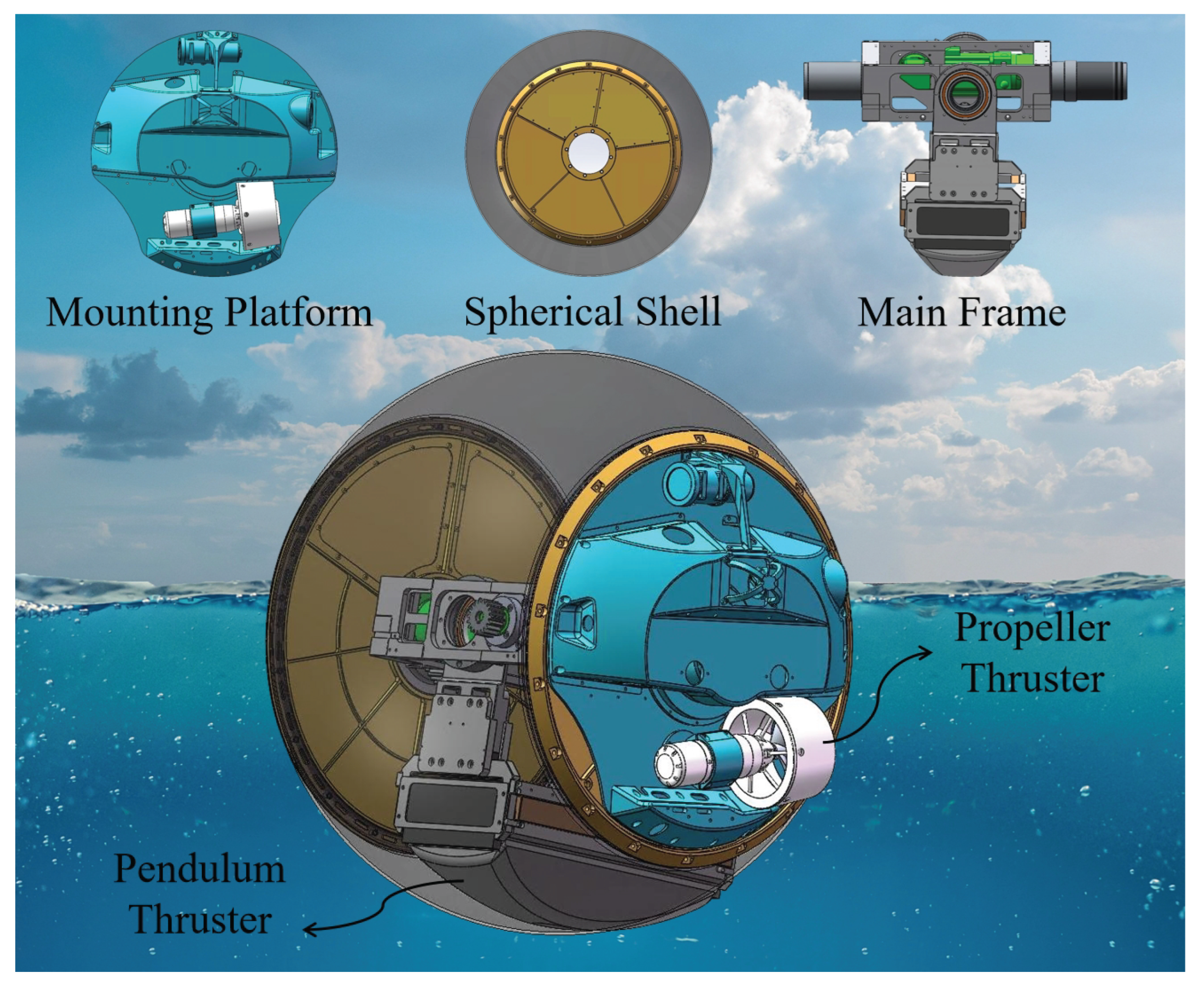
Figure 2.
Schematic illustration of the amphibious spherical robot tipping in water. (a) Tilting to the left. (b) Tilting to the right. (c) In a stable state.
Figure 2.
Schematic illustration of the amphibious spherical robot tipping in water. (a) Tilting to the left. (b) Tilting to the right. (c) In a stable state.
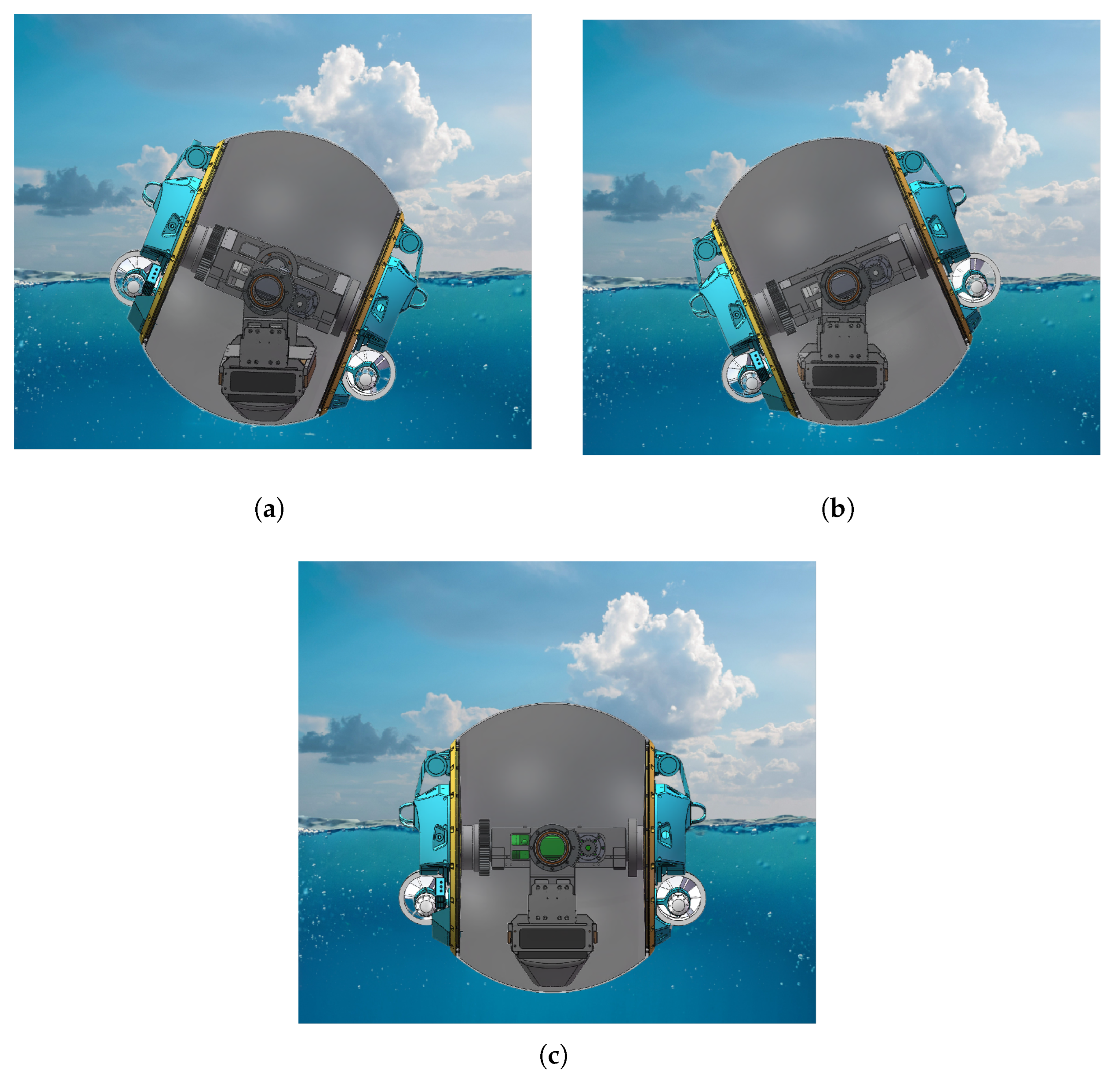
Figure 3.
Hydrodynamic Structure Features: (a) Contrasting Water-Facing Surface Designs (Spherical Cap vs. V-Shaped). (b) Submerged Body Geometries (ASR-DPS vs. KCS).
Figure 3.
Hydrodynamic Structure Features: (a) Contrasting Water-Facing Surface Designs (Spherical Cap vs. V-Shaped). (b) Submerged Body Geometries (ASR-DPS vs. KCS).
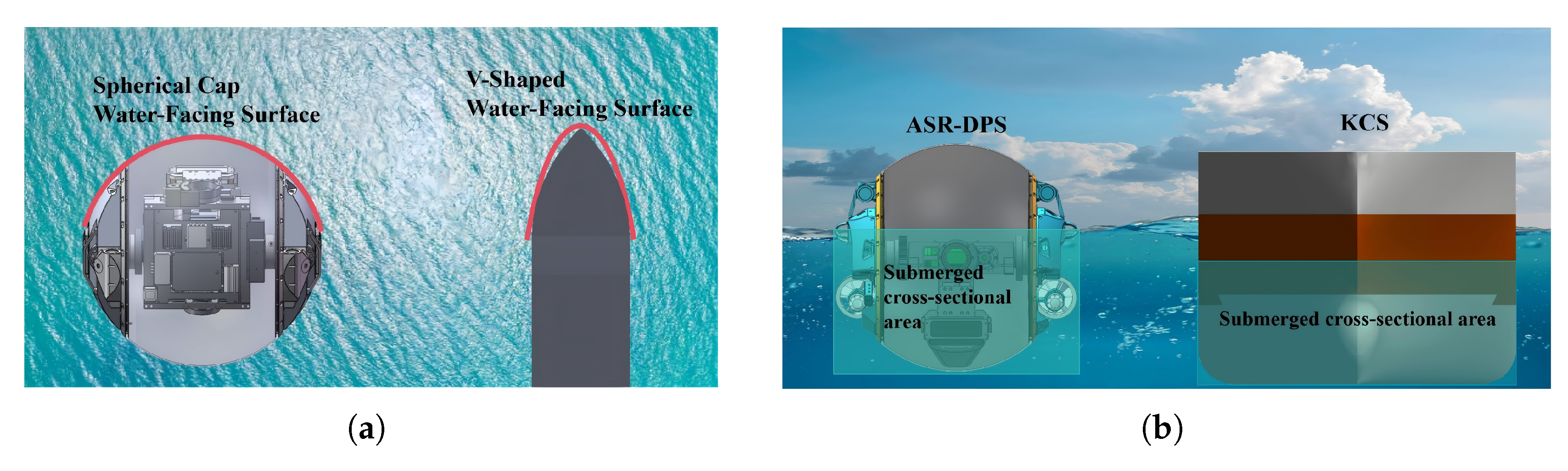
Figure 4.
Comparison of Surface Motion Characteristics of Spherical Robots (a) Position. (b) Vorticity. (c) Pressure. (d) Velocity.
Figure 4.
Comparison of Surface Motion Characteristics of Spherical Robots (a) Position. (b) Vorticity. (c) Pressure. (d) Velocity.
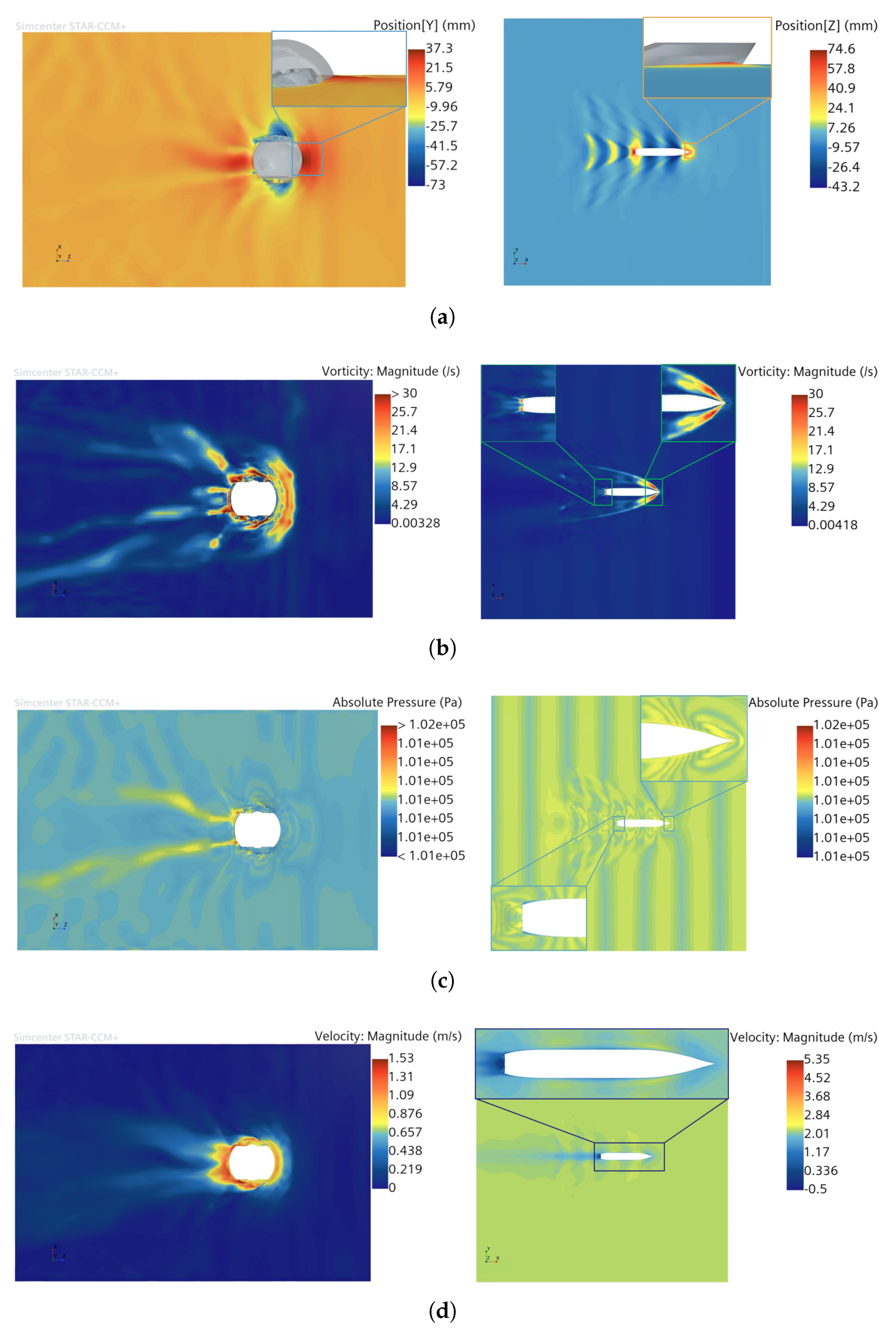
Figure 5.
Reference frames associated with the robot.
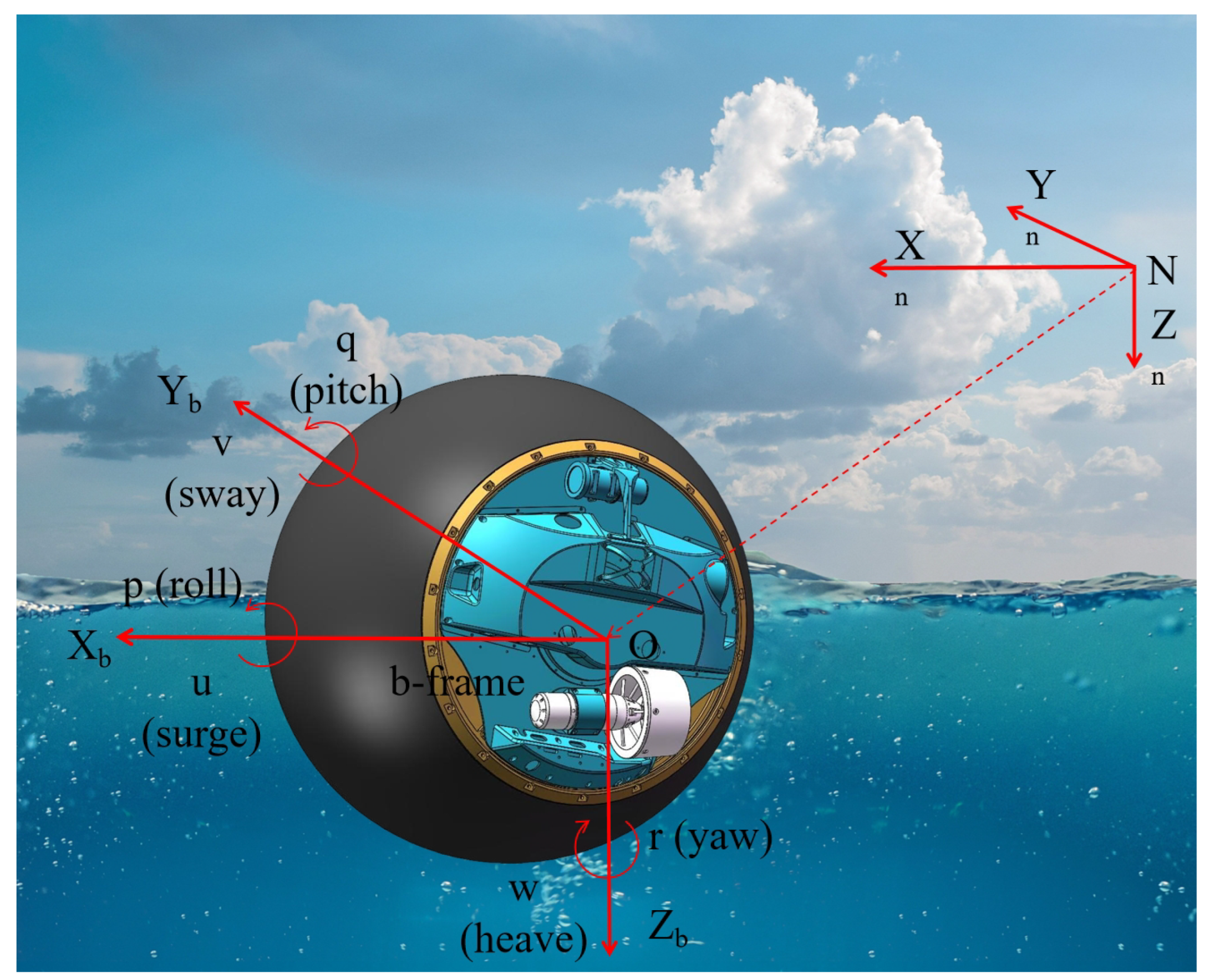
Figure 7.
Circle Test Data Plots: (a) Surge velocity and yaw rate in Test 1. (b) Surge velocity and yaw rate in Test 2. (c) Roll and pitch angle variations in Test 1. (d) Roll and pitch angle variations in Test 2. (e) and (f) Images of the robot during real-world circle tests.(g) Trajectory plot.
Figure 7.
Circle Test Data Plots: (a) Surge velocity and yaw rate in Test 1. (b) Surge velocity and yaw rate in Test 2. (c) Roll and pitch angle variations in Test 1. (d) Roll and pitch angle variations in Test 2. (e) and (f) Images of the robot during real-world circle tests.(g) Trajectory plot.
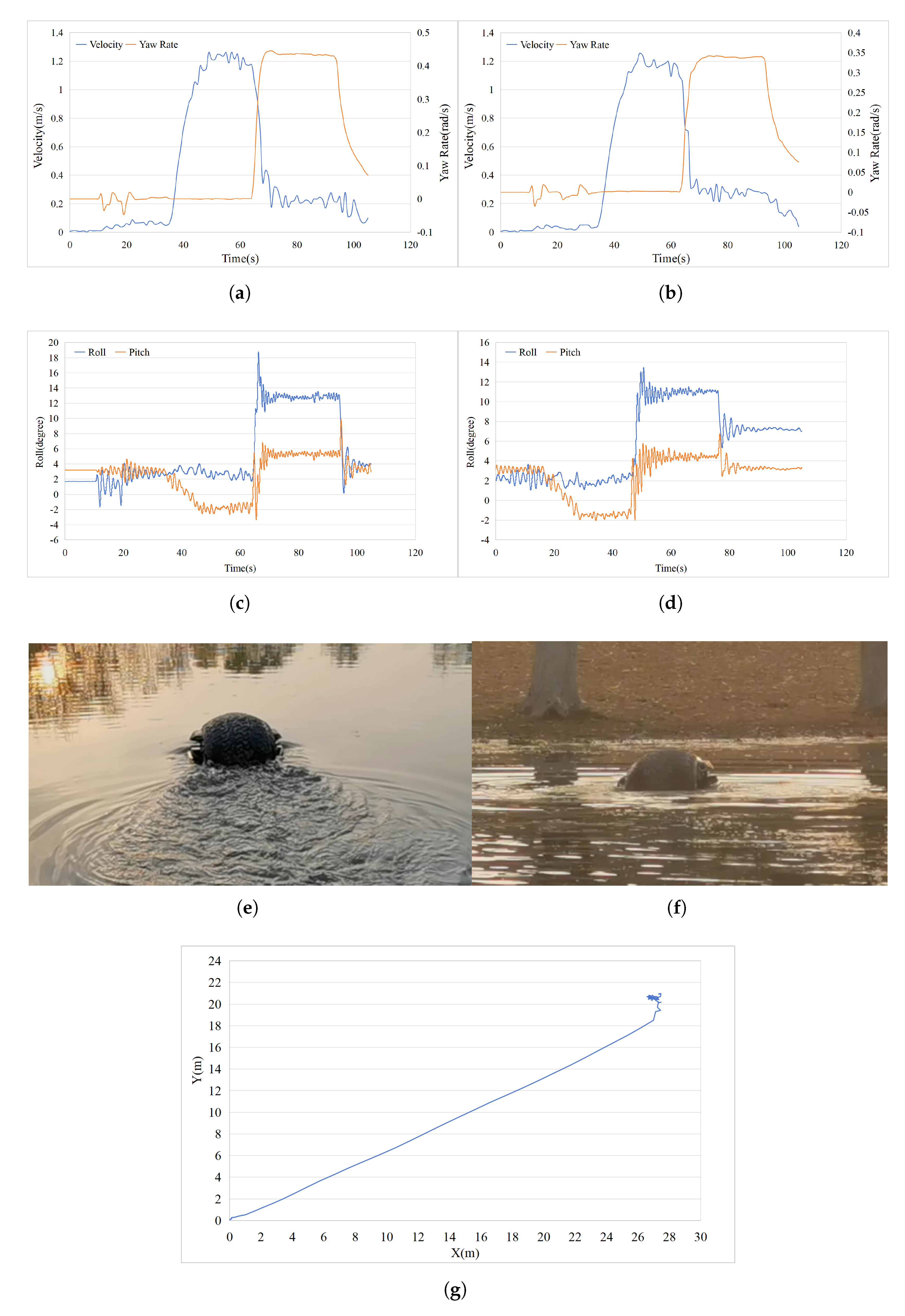
Figure 8.
Zig-zag Test Data Plots: (a) Surge velocity and yaw rate (b) Roll and pitch angle variations (c) Yaw variations (d) Trajectory plot.
Figure 8.
Zig-zag Test Data Plots: (a) Surge velocity and yaw rate (b) Roll and pitch angle variations (c) Yaw variations (d) Trajectory plot.
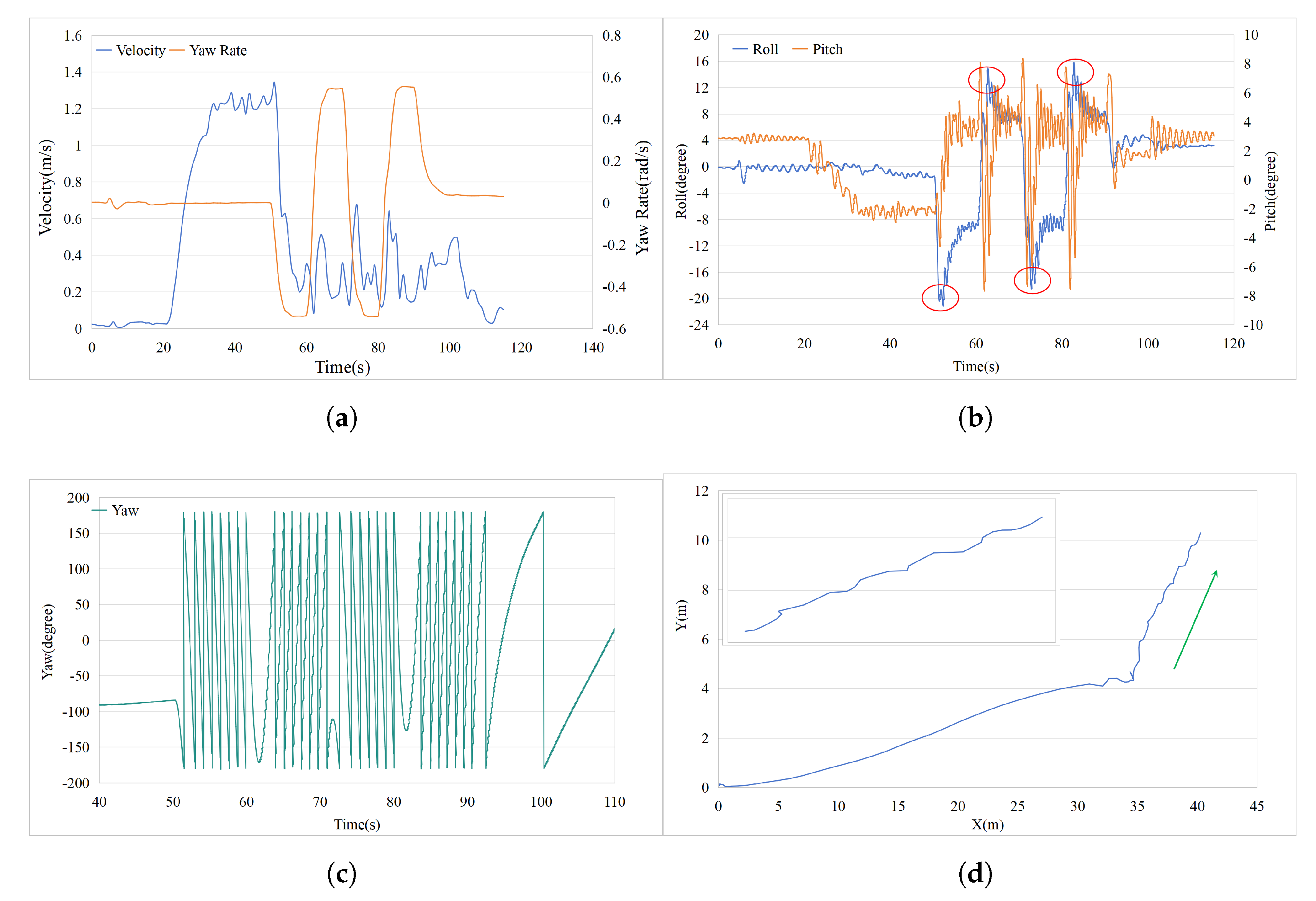
Figure 9.
Surface Motion of the Water Ball Robot Under the Pendulum Propulsion System: (a)Photograph. (b)Schematic Diagram
Figure 9.
Surface Motion of the Water Ball Robot Under the Pendulum Propulsion System: (a)Photograph. (b)Schematic Diagram
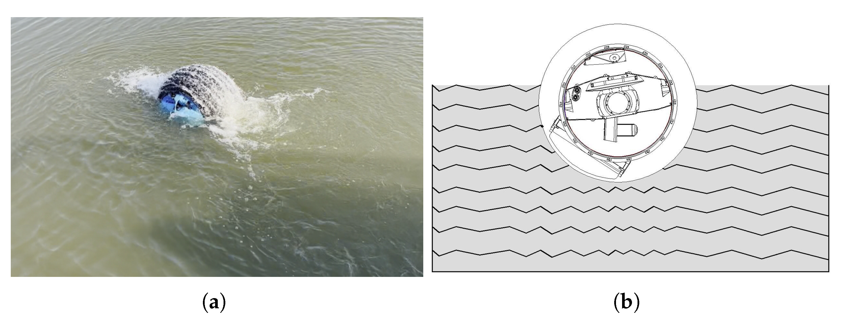
Figure 10.
Simulation Results of the SMC−NUD: (a) Surge Speed. (b) Yaw Angle. (c) Yaw Rate. (d) Control Inputs. (e) Trajectory Tracking.
Figure 10.
Simulation Results of the SMC−NUD: (a) Surge Speed. (b) Yaw Angle. (c) Yaw Rate. (d) Control Inputs. (e) Trajectory Tracking.
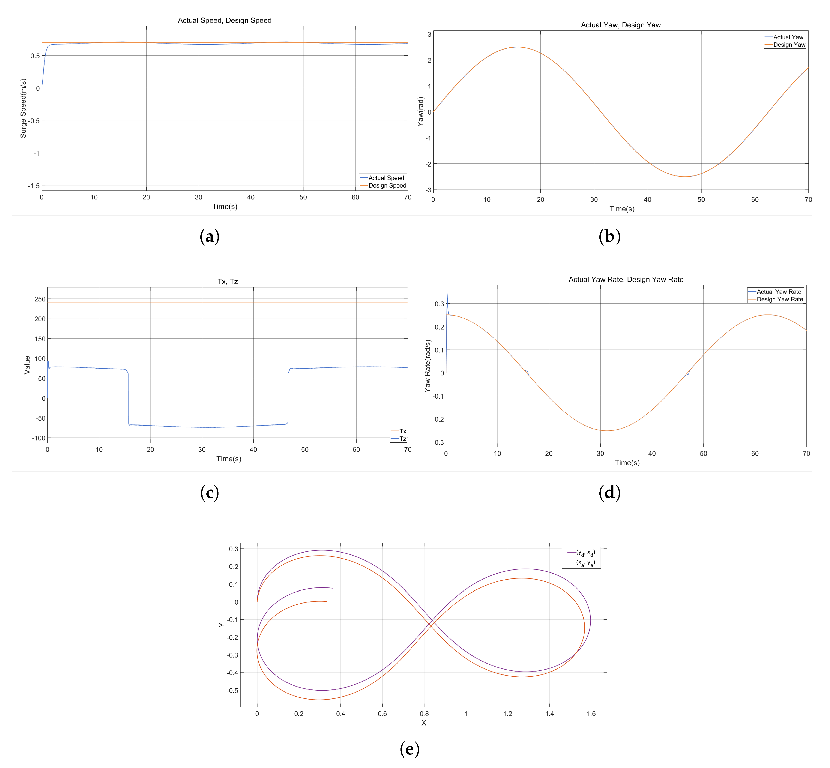
Table 3.
Hydrodynamic Parameter Calculation Formulas[22]
Table 3.
Hydrodynamic Parameter Calculation Formulas[22]
| Coefficient Name | Non-Dimensional Factor | Dimensional Term |
|---|---|---|
| 0.5 | [15] | |
| 0.5 | [15] | |
| 0 | 0 | |
| – | See Table 1 | |
| 0.5 | ||
| 0.02 | ||
| – | See Table 1 | |
| 1 | ||
| 1 |
Table 4.
Circle Test Settings.
| Time (s) | Port Propeller Throttle | Starboard Propeller Throttle |
|---|---|---|
| First Test | ||
| 0–50 (acceleration phase) | 0 → 100% | 0 → 100% |
| 50–70 (constant-speed cruising phase) | 100% | 100% |
| 70–100 (turning maneuver phase) | 80% | –80% |
| Second Test | ||
| 0–50 (acceleration phase) | 0 → 100% | 0 → 100% |
| 50–70 (constant-speed cruising phase) | 100% | 100% |
| 70–100 (turning maneuver phase) | 60% | –60% |
Table 5.
Zig-zag Test Settings.
| High Value (%) | Low value (%) | Title 3 |
|---|---|---|
| 100 | 0 | High and low throttle inputs were alternately applied to the left and right propeller thrusters. The inputs were switched every 10 seconds, with a total of four switches—two for each side—resulting in a total test duration of 40 seconds. [26] |
Disclaimer/Publisher’s Note: The statements, opinions and data contained in all publications are solely those of the individual author(s) and contributor(s) and not of MDPI and/or the editor(s). MDPI and/or the editor(s) disclaim responsibility for any injury to people or property resulting from any ideas, methods, instructions or products referred to in the content. |
© 2025 by the authors. Licensee MDPI, Basel, Switzerland. This article is an open access article distributed under the terms and conditions of the Creative Commons Attribution (CC BY) license (http://creativecommons.org/licenses/by/4.0/).
Copyright: This open access article is published under a Creative Commons CC BY 4.0 license, which permit the free download, distribution, and reuse, provided that the author and preprint are cited in any reuse.


