
Submitted:
02 June 2025
Posted:
02 June 2025
You are already at the latest version
Abstract
Hypergolic ionic liquid fuels are promising alternatives to toxic hydrazine-based propellants. This study investigates the combustion performance of a fuel composed of 1-ethyl-3-methylimidazolium thiocyanate ([EMIM][SCN]) and copper(I) thiocyanate (CuSCN) with 95 wt% hydrogen peroxide (H2O2) in a 50 N rocket engine. Two injector designs, DM1 (low pressure drop) and DM2 (high pressure drop), were tested at chamber pressures of 10 and 15 bar. The DM1 injector at 15 bar chamber pressure showed higher combustion efficiency but suffered from strong pressure oscillations (>10% instability). Switching to the DM2 injector reduced instability (< 5%) by increasing the pressure drop. Combustion stability was improved as the fuel injector orifice diameter/fuel jet velocity (D/V) decreased. FFT analysis showed a dominant instability frequency of 220 Hz with DM1, which was significantly reduced with DM2. Results highlight that injector design and pressure drop are key factors in improving combustion stability for green hypergolic propulsion systems.
Keywords:
hypergolic fuel
; green propellant
; combustion instability
; ionic liquids
; hydrogen peroxide
1. Introduction
The development of low-toxicity hypergolic propulsion systems is a rapidly growing area of research, driven by the increasing demand for safer and more environmentally sustainable rocket propulsion technologies. Conventional hypergolic propellants, hydrazine and their derivatives are highly toxic, flammable, and carcinogenic. The permissible exposure limit for hydrazine is as low as 0.01 ppm, significantly below the odor detection threshold (1-3 ppm), making it hazardous even when undetectable by smell (Table 1). Furthermore, the commonly used oxidizer dinitrogen tetroxide (N2O4) is also extremely toxic and corrosive. In liquid form, N2O4 exists in equilibrium with nitrogen dioxide (NO2) vapors, which, upon contact with human tissue, especially within the respiratory system, can form nitric or nitrous acid, leading to severe health issues and even death upon prolonged exposure.
In light of these concerns, there has been a significant shift toward developing green hypergolic propulsion systems. High-test peroxide (HTP) has emerged as a promising oxidizer due to its high density, low vapor pressure, ease of handling, and environmentally benign combustion products [1,2]. Several pioneering studies have been developed and evaluated the low-toxicity hypergolic propellants using HTP, including research from institutions such as the Naval Air Warfare Center [3], Purdue University [4], Korea Advanced Institute of Science and Technology (KAIST) [5,6,7], the National Institute for Space Research [8], the German Aerospace Center (DLR) [9,10], Lukasiewicz Institute of Aviation [11]. Despite these efforts, no green hypergolic propulsion system has yet reached commercial deployment, and only a few fuel combinations are currently considered viable for future applications.
Recent advancements in ionic liquid (IL) technology have introduced new opportunities in green hypergolic propulsion [12,13,14]. Ionic liquids possess desirable properties such as low vapor pressure, high energy density, and the ability to undergo hypergolic reactions with hydrogen peroxide. Notably, in 2022, DLR conducted the first hot-firing test of a green hypergolic propellant system, HIP_11, which combined 97% H2O2 with an ionic liquid fuel comprising 1-ethyl-3-methylimidazolium thiocyanate ([EMIM][SCN]) and 5 wt% copper(I) thiocyanate (CuSCN) [10]. This system achieved steady-state combustion in a 25 N thruster, demonstrating combustion efficiencies exceeding 93%. Additional studies on combustion performance were conducted using various injector configurations (triplet and pentad) and chamber geometries [9]. It was found that a 2-on-1 impinging injector provided more stable combustion, and elongated combustion chambers (with a characteristic length of 1.2 m) yielded better performance than shorter designs. However, high-frequency pressure oscillations (~1000 Hz) were still observed, posing risks of structural damage. Thus, further evaluations of these propellants across different thruster scales are necessary.
Space Solutions Co. Ltd. has also contributed to the advancement of HTP-based green hypergolic systems. In our recent studies, the combustion characteristics of an ionic liquid fuel, ILethCu01, combined with 95 wt% H2O2, were investigated in a 50 N rocket engine [5]. This combination achieved combustion efficiencies exceeding 90% in several cases, although instabilities ranging between 3% and 5% were noted. Further experimental campaigns explored the same fuel formulation ([EMIM][SCN] + CuSCN) with injector and chamber design variations. Two injector types such as DM1 (low pressure drop) and DM2 (high pressure drop) were developed, and tests were conducted at chamber pressures of 10 and 15 bar. The influence of these parameters on combustion efficiency and stability was systematically assessed.
2. Materials and Methods
The ionic liquid [EMIM][SCN] (95%) and copper(I) thiocyanate (CuSCN, 99%) were purchased from Sigma-Aldrich. The oxidizer, 95 wt% hydrogen peroxide (H2O2), was obtained from HABO, China. The concentration was measured prior to testing using a refractometer was 95.5 (±2)%.
Initially, various concentrations (1-10 wt%) of CuSCN were dissolved in [EMIM][SCN] to prepare fuel blends (Figure 1). Hypergolic drop tests were then conducted, using neat [EMIM][SCN] and solution with CuSCN, with 95 wt% H2O2. High-speed camera (4000 fps, FASTCAM Mini UX-100, Photron) was used to capture the ignition event. Based on drop test results, the optimized fuel, ‘ILCu01’, formulation was further characterized. Differential scanning calorimetry (DSC) was performed to evaluate thermal properties using a DSC 4000 instrument (PerkinElmer) with a nitrogen flow rate of 20 mL/min. Weight loss as a function of temperature was analyzed using a simultaneous DSC-TGA system (STA 6000, PerkinElmer), also under a nitrogen flow rate of 20 mL/min. Physical properties such as density and viscosity were measured using an Anton Paar viscometer (SVM 3001 Cold Properties).
Theoretical performance of the ILCu01/95 wt% H2O2 propellant was calculated using NASA Chemical Equilibrium with Applications (CEA) code. An infinite-area combustion model under frozen flow conditions was applied. The heat of combustion for CuSCN, measured via bomb calorimeter, was used to determine heat of formation. The heats of formation used for [EMIM[SCN], CuSCN, and H2O2 were 52.80 kJ/mol, 308.69 kJ/mol, and –187.79 kJ/mol, respectively. Calculations were performed at a constant chamber pressure of 10 bar and nozzle expansion ratio of 100, across a range of oxidizer-to-fuel (O/F) ratios. The specific impulse and characteristic velocity were calculated.
The static fire test bed setup is described in previous literature, and a schematic along is provided in the Supporting Information section 1. The engine was designed based on theoretical calculations, targeting a chamber pressure of 10 bara and a thrust of 50 N. Single-element, unlike triplet (O-F-O) injectors were developed: Development Model 1 (DM1) and Development Model 2 (DM2). The impingement angle was fixed at 90°. The DM1 injector was designed with a pressure drop equal to 20% of the chamber pressure, as a baseline for liquid thruster ignition [15,16]. Based on the hot-fire test results, the DM2 injector was developed with a higher pressure drop of 40–50% of the chamber pressure to improve combustion stability. Static fire tests were performed with a maximum duration of 2 seconds, across different O/F ratios. Key performance parameters such as experimental characteristic velocity, combustion efficiency, and combustion instability were calculated using experimental data, with equations reported elsewhere [5]. The FFT analysis was performed using Matlab wavelet function.
3. Results and Discussion
3.1. Hypergolic Drop Test
Hypergolic value measurement in terms of ignition delay time (IDT) has significance in choosing the fuel candidate for propellant application. Ignition delay time can be measured by calculating the time required between the fuel with oxidizer contact and first visible flame seen. Atmospheric drop test method were applied to measure the IDT, having oxidizer drop and fuel pool. The distance between the oxidizer falling drop point and fuel pool surface was kept constant throughout the experiment. Initially, the hypergolic ignition of [EMIM][SCN] was measured with 95 wt% H2O2 and average IDT was 24 ms. Further, 1-10 wt% CuSCN in [EMIM][SCN] was also tested with 95 wt% H2O2 and the average IDT was reduced to 13 ms for 5 wt% CuSCN as shown in Figure 2. Further increases in additive concentration did not improve the IDT. Similar results were also reported by DLR [10]. The fuel combination 5 wt% Cu in [EMIM][SCN] named hereafter as ‘ILCu01’. Figure 3 represents the high speed camera images shows the lowest IDT of [EMIM][SCN] and ILCu01 fuel. The ignition of [EMIM][SCN] with 95 wt% H2O2 was smooth compared to noisy combustion of ILCu01. This may be due to the rapid decomposition of hydrogen peroxide on copper ion.
3.2. Physicochemcial Properties of Fuel
Ionic liquids are viscous material compared to hydrazine-based fuels [9]. The viscosity of EMIMSCN was 22 mPa·s. However, addition of additive to ionic liquid makes more viscous, ILCu01 revealed a viscosity of 32 mPa·s. Low viscous fluid is recommended for the better mixing with oxidizer. In comparison with HIP_11 fuel, ILethCu01 fuel has low viscosity that can lower the energy required for fuel pressurization in order to get effective mixing of fuel with oxidizer. The density of ILCu01 was higher than MMH fuel, which can help to improve the density specific impulse of propellant. Long liquideous range from -80 to 290 °C demonstrates the working ability of fuels at different temperature environment (Figure 4 and Figure 5).
3.3. Theoretical Performance
The rocket performance such as characteristics velocity and specific impulse are significant factor to measure the efficiency of propellant. In chemical propulsion, the performance in order to cryogenic propellant>liquid propellant>solid propellants. The NASA chemical equilibrium calculations (CEA) helps to find the best performance chemicals for rocket engine without testing on field [17,18]. Based on the theoretical results it was easy to select the fuel for practical application. The performance parameters can be adjusted according to the engine design either by seal level or vacuum. Sea level performance always lower than the vacuum level performance. The propellant selection is significant factor to decide high performance or low performance fuel for rocket engine. Adiabatic temperature and oxidizer to fuel ratio helps to design the rocket engine. The specific impulse and characteristics velocity was increased then decreased with increasing O/F ration. A concave downward curve was observed with optimum performance of C* of 1547 m/s at O/F 3.7. However, the optimum Isp was 305 observed at O/F of 3.8 (Figure 6). This may be due to the C* performance is independent on nozzle dimensions. Specific impulse is depend on the nozzle parameters. Hence small change was observed. This does mean that the maximum performance observed at optimum O/F means the maximum combustion of propellants can be occurs on that ratio. Considering the optimum value of O/F, low value means the fuel rich condition and high value means the oxidizer rich condition. Low and high O/F having lower performance means the, combustion is inefficient.
An adiabatic temperature of ILCu01/95 wt% H2O2 was 2700 K. which is still lower than MMH/NTO propellant.
3.4. Hot Fire Test Results
3.4.1. Mass Flow Rate Calibration
Prior to conducting the firing campaign, the calibration of the mass flow rate is a critical step. Several methods are available for measuring mass flow, and in this study, an orifice flow meter was employed. By adjusting a metering valve downstream, the differential pressure across the orifice was varied, resulting in corresponding changes in mass flow rate. Multiple measurements were taken at different differential pressures, and the results are presented in Figure 7.
As shown in Figure 7a, the oxidizer mass flow rate exhibited an approximately linear relationship with the orifice pressure difference. Since hydrogen peroxide behaves as a Newtonian fluid with low viscosity, the curve fitting was accurate. In Figure 7b, the fuel mass flow rate also showed a linear trend with respect to the orifice pressure difference. However, due to the thixotropic nature and high viscosity of the fuel, the fitted curve did not intersect all measured data points as closely as it did for the oxidizer.
Three different tests were conducted by considering the injector model/chamber pressure/fuel such as DM1/10 bar/ILCu01, DM1/15 bar/ILCu01, DM2/10 bar/ILCu01. The stoichiometric O/F of this propellant was 3.8. As the fuel and oxidizer was controlled by metering valve keeping constant chamber tank pressure, it was difficult to adjust the exact mass flow rate at stoichiometric ratio. However, the mass flow rate of fuel and oxidizer was near to the O/F at most of the cases (Figure 8).
3.4.2. Thruster Behavior During Firing Test
Initially, the firing tests were conducted using the DM1 injector at two different chamber pressures, 10 bar and 15 bar and further DM2 injector used with 10 bar chamber (Supporting Information Section 2). Total three test were conducted by using ILCu01/95 wt% H2O2 propellant. A representative case with a similar O/F ratio for DM1 at 10 bar and 15 bar was selected for comparison (Figure 9). In both tests, the oxidizer and fuel mass flow rates were set at 17 g/s and 3.7 g/s respectively, resulting in an O/F ratio of 4.6 and a relatively high total mass flow rate.
The pressure drop for Test 11 (DM1/10 bar) was 1.79 bar and 1.81 bar for the fuel and oxidizer injectors, respectively. A similar pressure drop was also observed in the DM1/15 bar chamber test (Test 12, Supporting Information Table 2). Figure 9a,b clearly illustrate the differences in chamber pressure oscillations. The more pronounced oscillations exhibited at the 15 bar chamber; however, the characteristic velocity and combustion efficiency improved by approximately 147 m/s and a corresponding 9%, respectively, when compared to the 10 bar chamber (Test 10, DM1/10 bar).
Despite these improvements, combustion instability was higher for the 15 bar chamber experiment. Combustion instability values for DM1/10 bar (Test 10) and DM1/15 bar (Test 12) were 9.4% and 13.4%, respectively. A Fast Fourier Transform (FFT) analysis was conducted to compare the instability intensities and peak frequencies across the tests. Previous studies [19] have shown that modifications in propellant properties or thruster geometry, particularly the characteristic length, can reduce instabilities. The frequency amplitude graph clearly showed differences in instability amplitudes between the 10 bar and 15 bar chambers for the DM1 injector (Figure 10). A high-intensity low-frequency instability was observed in the 15 bar chamber compared to the 10 bar chamber. The peak frequency recorded by the FFT for the 15 bar test was 253 Hz, with an amplitude of 0.75 bar. In contrast, for the 10 bar test the peak frequency was 222 Hz with an amplitude of 0.27 bar. These results clearly demonstrate that combustion chamber pressure significantly influences combustion instability similar with the DLR study [9]. WSST time-frequency studies also reveal the instability over time (Supporting Information Figure 2). Further testing is necessary to analyze instability behavior across a broader range of chamber pressures. It was assessed that the low injector pressure drop may have contributed to the observed instabilities. Therefore, to improve stability, a new injector model, DM2, was developed, targeting a pressure drop of 40–50% of the chamber pressure.
The performance of the DM1 and DM2 injectors was compared at a chamber pressure of 10 bar (Figure 11). For consistency, the oxidizer mass flow rate was maintained at 17 g/s, and the fuel mass flow rate was adjusted to 3.5 g/s, resulting in an O/F ratio of 4.8 for both tests. The pressure drop from the oxidizer and fuel injectors for the DM2 injector (Test 12) was 4.2 bar and 5.2 bar, respectively. This higher pressure drop may have contributed to the reduced instability observed with the DM2 injector compared to DM1.
In comparison with DM1, the combustion instability for DM2 was notably lower, below 5% (Supporting Information Table 3). The FFT analysis for the DM2 injector did not yield a clear instability frequency, likely due to a lower data sampling rate of 1000 Hz, whereas DM1 tests were conducted at 10,000 Hz. Consequently, while instabilities were still observed in test 12 (Supporting information Figure 3a), particularly around a peak frequency of 220 Hz, these results require confirmation through higher-resolution testing.
Based on the combustion data, experimental characteristic velocities for DM1 and DM2 injector tests were calculated (Figure 12a), and combustion efficiency was estimated by comparing with the ideal characteristic velocity (Figure 12b). Combustion efficiency, defined as the ratio of experimental to theoretical characteristic velocity, was highest for the DM1/15 bar test. For example, the DM1/10 bar (Test 12) showed a characteristic velocity of 1226 m/s, whereas DM1/15 bar (Test 11) achieved 1280 m/s at a similar O/F ratio. Accordingly, the combustion efficiency for the 10 bar test was 79%, compared to 83% for the 15 bar test.
For the DM2 injector at 10 bar, the maximum combustion efficiency was 75%, which was lower than that of DM1. However, combustion instability was significantly lower for DM2 (below 5%) compared to DM1, which showed instabilities exceeding 5% for both 10 and 15 bar tests. These findings suggest that injector pressure drop plays a critical role in steady operation of thruster.
Furthermore, the relationship between fuel orifice diameter to velocity ratio (D/V)fuel and combustion instability was investigated (Figure 13). Results indicated that combustion instability decreased as (D/V)fuel decreased. Using the DM2 injector, it was observed that when (D/V)fuel dropped below 0.05, stable combustion was achieved. Thus, estimating (D/V)fuel during the thruster design phase may allow for optimization of thruster performance while minimizing instabilities.
4. Conclusions
In this study, the influence of injector design was evaluated for a thruster using hydrogen peroxide and a hypergolic fuel. The ignition delay time (IDT) and thermal properties of ILCu01 were reproduced to confirm the performance and thermal stability, and the results were compared with studies from DLR. Furthermore, ILCu01 was tested with 95% H2O2 in a 50 N thruster to investigate combustion behavior under different injector designs. The DM1 injector design was initially considered with a 10-20% injector pressure drop relative to the chamber pressure. However, it was found that this pressure drop was not sufficient to sustain steady-state combustion, despite yielding better combustion efficiency. In contrast, the DM2 injector design, which employed a 40-50% pressure drop, showed improved combustion stability. Additionally, the ratio between the injector diameter and fuel injection velocity appears to determine a critical threshold (~0.05 m/s), beyond which combustion instability occurs. Further experiments are recommended to verify whether these design parameters are applicable to other types of propellants.
Supplementary Materials
The following supporting information can be downloaded at the website of this paper posted on Preprints.org.
Abbreviations
The following abbreviations are used in this manuscript:
| IL | Ionic liquid |
| [EMIM][SCN] | 1-ethyl methyl imidazolium thiocyanate |
| IDT | Ignition delay time |
| FFT | Fast Fourier Transform |
| WSST | Wavelet Synchrosqueezed transform |
References
- Rarata, G.; Florczuk, W. Novel Liquid Compounds As Hypergolic Propellants With HTP. J. KONES Powertrain Transp. 2016, 23, 271–278. [Google Scholar] [CrossRef]
- Clark, J. IGNITION ! An Informal Histroy of Liquid Propellants; Rutgers University Press: New Brunswick, USA, 1972; ISBN 0813507251. [Google Scholar]
- Rusek, J.J.; Minthorn, M.K.; Purcell, N.L.; Pavia, T.C.; Grote, J.R.; Hudson, G.C.; Mckinney, B. Non-Toxic Homogeneous Fuel (NHMF) Development for Hypergolic Bipropellant Engines; 1996;
- Austin, B.L.; Heister, S.D. Characterization of Pintle Engine Performance for Nontoxic Hypergolic Bipropellants. 38th AIAA/ASME/SAE/ASEE Jt. Propuls. Conf. Exhib. 2005, 21. [Google Scholar] [CrossRef]
- Bhosale, V.K.; Lee, K.; Yoon, H.; Kwon, S. Green Bipropellant: Performance Evaluation of Hypergolic Ionic Liquid-Biofuel with Hydrogen Peroxide. Fuel 2024, 376, 132688. [Google Scholar] [CrossRef]
- Kang, H.; Jang, D.; Kwon, S. Demonstration of 500 N Scale Bipropellant Thruster Using Non-Toxic Hypergolic Fuel and Hydrogen Peroxide. Aerosp. Sci. Technol. 2016, 49, 209–214. [Google Scholar] [CrossRef]
- Kang, H.; Lee, E.; Kwon, S. Suppression of Hard Start for Nontoxic Hypergolic Thruster Using H2O2 Oxidizer. J. Propuls. Power 2017, 33, 1111–1117. [Google Scholar] [CrossRef]
- Maschio, L.J.; de Araújo, E.P.; Pereira, L.G.F.; Gouvêa, L.H.; Vieira, R. Assessing the Performance of a Green Liquid Fuel Hypergolic with Hydrogen Peroxide in a 50 n Bipropellant Thruster. Int. J. Energ. Mater. Chem. Propuls. 2021, 20, 21–30. [Google Scholar] [CrossRef]
- Sarritzu, A.; Pasini, A.; Merz, F.; Werling, L.; Lauck, F. Experimental Investigation of Combustion Performance of a Green Hypergolic Bipropellant Based on Hydrogen Peroxide. Acta Astronaut. 2024, 219, 278–290. [Google Scholar] [CrossRef]
- Negri, M.; Lauck, F. Hot Firing Tests of a Novel Green Hypergolic Propellant in a Thruster. J. Propuls. Power 2022, 38, 467–477. [Google Scholar] [CrossRef]
- Lukasiewicz – Institute of Aviation New Green Hypergolic Propellant- Potential Gamechnager for in-Space Propulsion. Webpage 2023.
- Seo, M.; Bhosale, V.K.; Im, H.; Kwon, S. Performance Improvement of Triglyme-Based Fuels Using an Ionic Liquid with Hydrogen Peroxide. Combust. Flame 2024, 270, 113719. [Google Scholar] [CrossRef]
- Bhosale, V.K.; Gwak, J.; Kim, K.S.; Churchill, D.G.; Lee, Y.; Kwon, S. Rapid Ignition of “Green” Bipropellants Enlisting Hypergolic Copper (II) Promoter-in-Fuel. Fuel 2021, 297, 120734. [Google Scholar] [CrossRef]
- Bhosale, V.K.; Kulkarni, P.S. Ultrafast Igniting, Imidazolium Based Hypergolic Ionic Liquids with Enhanced Hydrophobicity. New J. Chem. 2017, 41, 1250–1258. [Google Scholar] [CrossRef]
- Huang, D.H.; Huzel, D.K. Modern Engineering for Design of Liquid-Propellant Rocket Engines; 1992; ISBN 1563470136.
- Suttan, G.P.; Biblarz, O. Rocket Propulsion Elements; Suttan, G.P., Biblarz, O., Eds.; 7th Editio.; John Wiley & Sons, Inc.: New York, 2001; ISBN 0471326429.
- Mcbride, B.J.; Gordon, S. Computer Program for Calculation of Complex Chemical Equilibrium Composition and Applications II. User Manual and Pogram Description. In NASA Reference Publication 1311; NASA Lewis Research Center Cleveland, Ohio 44135, 1996.
- Gordon, S.; McBride, B.J. Computer Program for Calculation Complex Chemical Equilibrium Compositions and Applications I. Analysis; NASA Lewis Research Center Cleveland, Ohio 44135, 1994; ISBN 1995001376.
- Kyuseop, K. Ignition and Reactive Spray Characteristics of High Test Peroxide-Based Rapid Hypergol, Korea Advanced Institute of Science and Technolgy, 2022.
Figure 1.
Weight percentages of CuSCN in [EMIM][SCN].
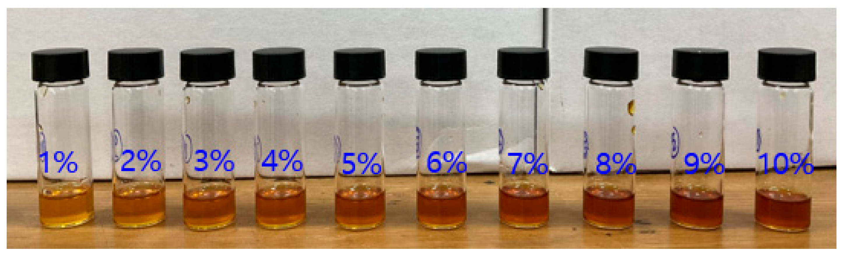
Figure 2.
Graph of ignition delay time of fuel with different concentration of additive with 95 wt% H2O2 (Fuel: EMIMSCN; additive: CuSCN).
Figure 2.
Graph of ignition delay time of fuel with different concentration of additive with 95 wt% H2O2 (Fuel: EMIMSCN; additive: CuSCN).
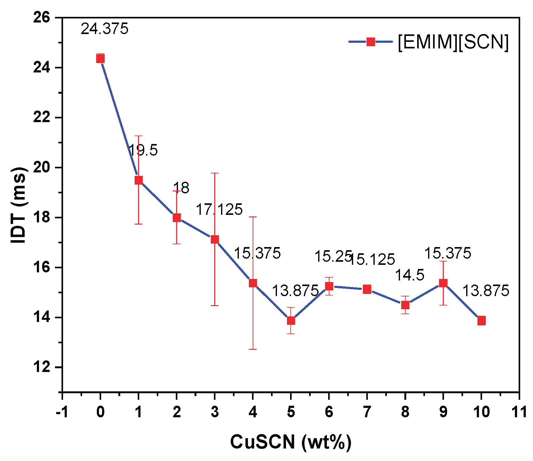
Figure 3.
(a) High speed camera images of EMIMSCN with 95 wt% H2O2 (b) High speed camera images of ILCu01 with 95 wt% H2O2.
Figure 3.
(a) High speed camera images of EMIMSCN with 95 wt% H2O2 (b) High speed camera images of ILCu01 with 95 wt% H2O2.
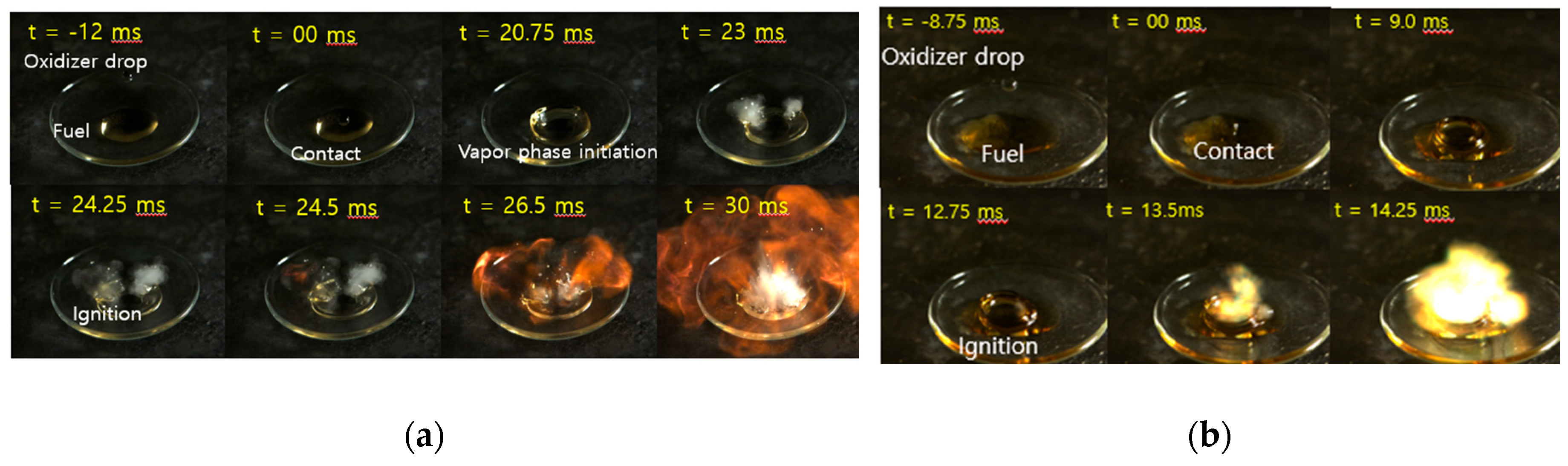
Figure 4.
Thermal analysis of fuels (a) simultaneous DSC-TGA analysis of [EMIM][SCN]; (b) Simultaneous DSC-TGA analysis of ILCu01.
Figure 4.
Thermal analysis of fuels (a) simultaneous DSC-TGA analysis of [EMIM][SCN]; (b) Simultaneous DSC-TGA analysis of ILCu01.
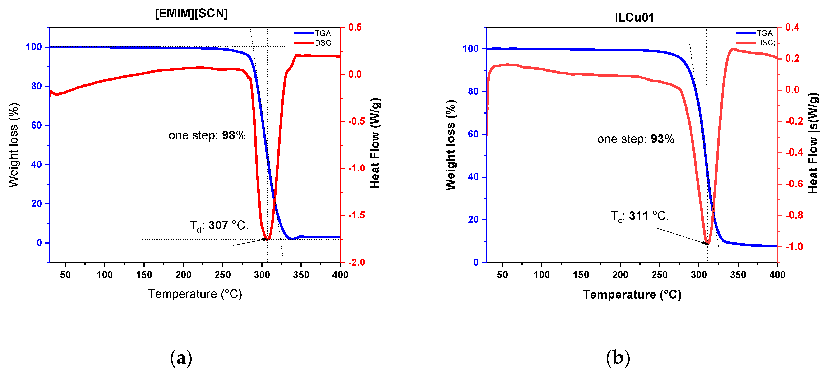
Figure 5.
Heat Flow and Temperature for each fuel.
Figure 6.
Theoretical analysis of ILCu01/95 wt% H2O2 propellant using NASA CEA code.
Figure 7.
Mass flow rate calibration (a) 95 wt% H2O2 oxidizer; (b) Fuel.
Figure 8.
Propellant mass flow rate and oxidizer to fuel ratio.
Figure 9.
Hypergolic combustion (a) DM1 injector 10 bar Chamber (Test 10), (b) DM1 injector 15 bar Chamber (Test 12).
Figure 9.
Hypergolic combustion (a) DM1 injector 10 bar Chamber (Test 10), (b) DM1 injector 15 bar Chamber (Test 12).
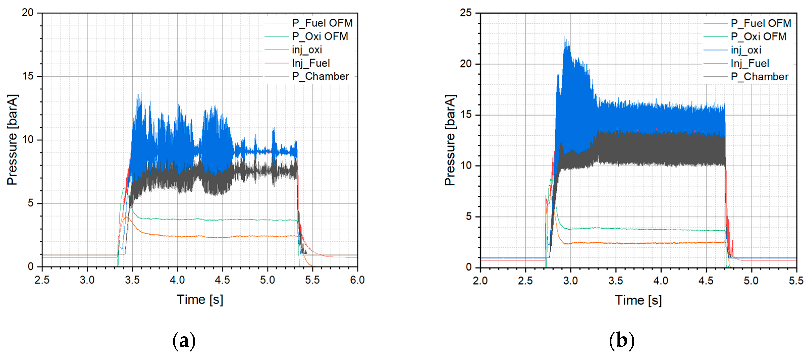
Figure 10.
Excitation frequency of the DM1 injector with 10 and 15 bar chamber.
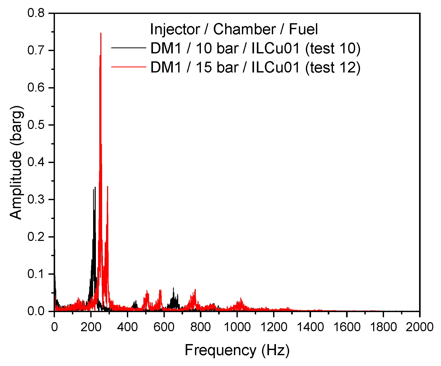
Figure 11.
Hypergolic combustion test of (a) DM1 injector 10 bar Chamber (Test 9); (b) DM2 injector 15 bar Chamber (Test 12).
Figure 11.
Hypergolic combustion test of (a) DM1 injector 10 bar Chamber (Test 9); (b) DM2 injector 15 bar Chamber (Test 12).
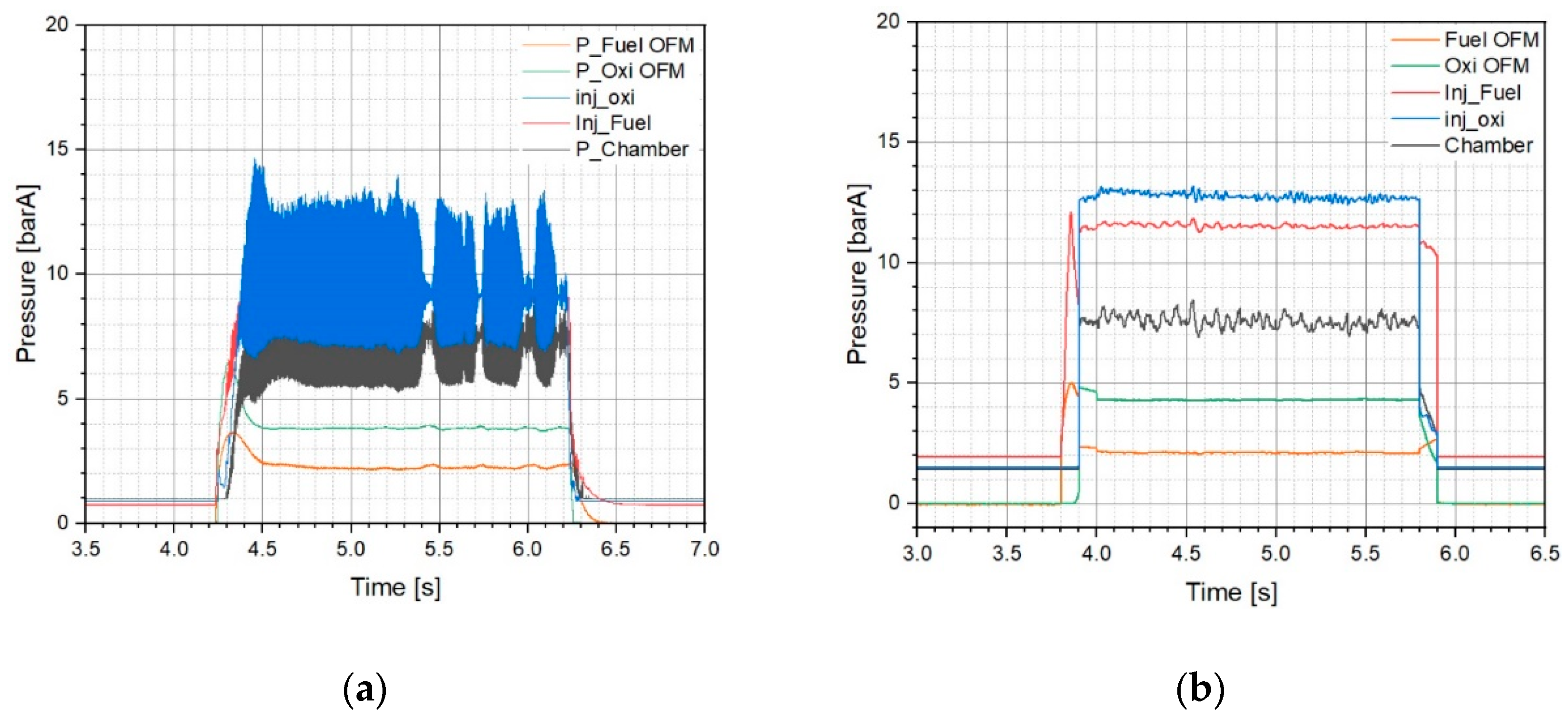
Figure 12.
Characteristic velocity (a) and efficiency (b) for each injector.
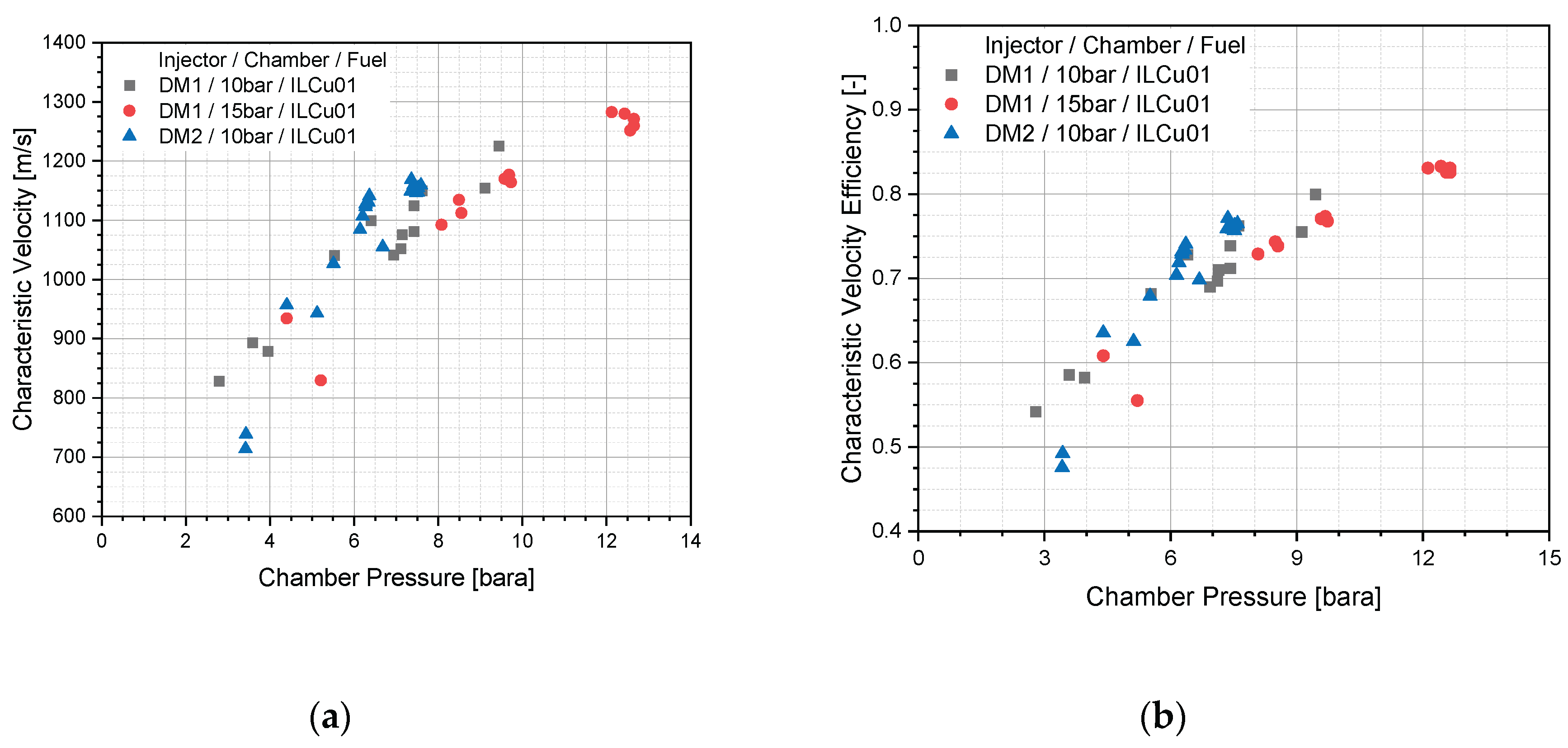
Figure 13.
D/V and Combustion instability relation.
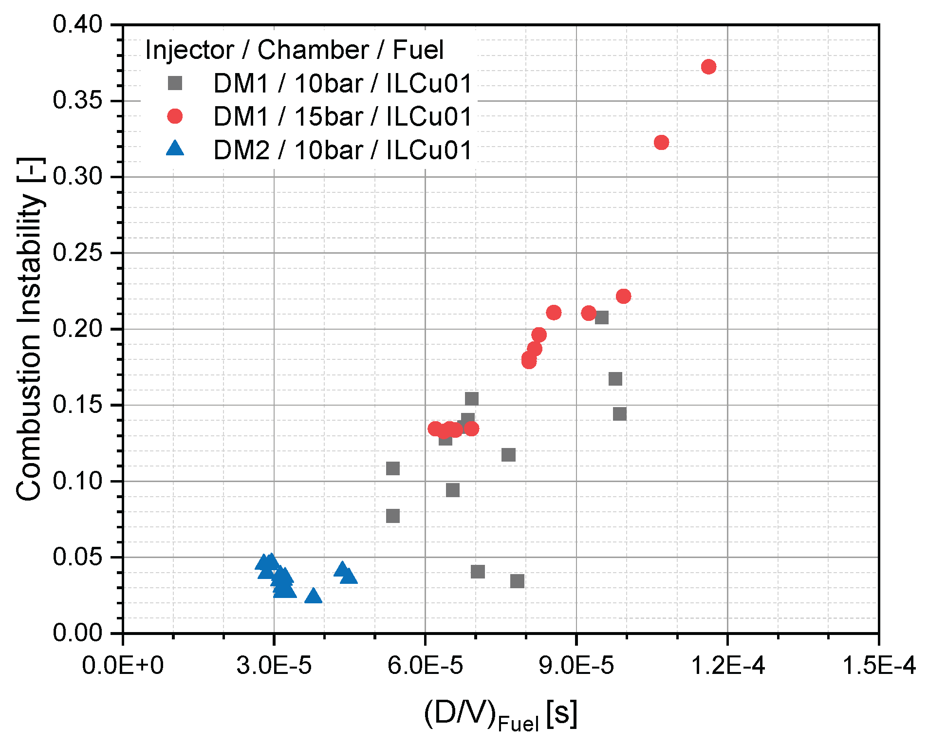

Table 1.
Comparative study of propellants.
| Order threshold, ppm | Exposure limit, ppm | Vapor pressure, psia at 25 °C. | Viscosity, cP | |
| Hydrazine | 2-3 | 0.01 | 0.96 | 0.97 at 298 K |
| MMH | 1-3 | 0.01 | 3.23 | 0.855 at 293 K |
| N2O4 | 1-3 | 3.0 | 17.4 | 0.47 at 293 K |
Disclaimer/Publisher’s Note: The statements, opinions and data contained in all publications are solely those of the individual author(s) and contributor(s) and not of MDPI and/or the editor(s). MDPI and/or the editor(s) disclaim responsibility for any injury to people or property resulting from any ideas, methods, instructions or products referred to in the content. |
© 2025 by the authors. Licensee MDPI, Basel, Switzerland. This article is an open access article distributed under the terms and conditions of the Creative Commons Attribution (CC BY) license (http://creativecommons.org/licenses/by/4.0/).
Copyright: This open access article is published under a Creative Commons CC BY 4.0 license, which permit the free download, distribution, and reuse, provided that the author and preprint are cited in any reuse.


