
Submitted:
29 May 2025
Posted:
30 May 2025
You are already at the latest version
Abstract
The use of CFRP for the strengthening of structures has been widely applied in the last decades. Most studies focused on the external bonding techniques between CFRP and the RC concrete substrates. However, premature delamination of CFRP from the concrete surface was a critical failure before reaching the ultimate capacity of fiber, which reduces the efficiency of this technique. Recently, the externally bonded reinforcement over grooves (EBOGR) and inside groove (EBRITG) method has been used as an alternative to the conventional method of externally bonded reinforcement (EB) to delay the delamination and improve the bond strength. This paper examines the improvement of the proposed hybrid strengthening system combining a layer of CFRP fabric reinforcement bonded inside a transverse grooves (EBRITG) method followed by the layers of over the grooves (EBOTGR) method for RC members, utilizing the surface area inside the grooves to anchor the CFRP against premature delamination and enhance the bonding strength. Seven RC beams were used in this program and tested in two stages. Five beams with different strengthening methods including over groove, inside groove, and hybrid system in the first stage and two beams strengthened using the hybrid system with anchorage of concrete cover for the second stage. The results indicated excellent enhancement in flexural capacity using hybrid system with anchored concrete cover by achieving increase of about 57% and 72.5% with 2 and 3 layers respectively, compared with that of over-grooves reinforcement (EBOGR) method, confirming the excellent bonding efficiency of the proposed strengthening method.
Keywords:
EBOGR
; EBRITG
; Hybrid strengthening system
; CFRP
; Transverse grooves
1. Introduction
The strengthening technique for CFRP composites bonded externally with concrete substrates has been applied extensively to various reinforced concrete [1,2,3,4], steel [5,6] and masonry structures [7,8]. However, the degradation of strengthening performance due to premature debonding of the externally bonded FRP from the concrete substrate reduces the efficiency of the use of the FRP material.
Therefore, postponing or preventing peeling of the CFRP from the concrete substrate can significantly increase the utilization of the capacity of the fiber. The anchorage systems can efficiently enhance the capability to transfer the stresses between the CFRP reinforcement and the concrete substrate [9], and consequently delay or inhibit the premature debonding of CFRP or cover separation failure.
The anchoring systems for the field of concrete structures have been utilized over the last decade, including mechanical anchorages [9,10], the gradient anchorage method [11,12], fiber-based anchorages [13,14], and the near-surface mounted techniques [15,16,17,18,19,20]. The NSM technique provides confinement for CFRP reinforcements and subsequently improves the bonding properties to eliminate the premature delamination between the CFRP reinforcement and the concrete. However, in some cases, the limitation of the concrete cover due to the presence of shear reinforcement, which is common in practical cases, will limit the cross-section of the FRP that can be applied in the NSM grooves, in addition to the challenge of prestressing the FRP reinforcement inside the grooves that often requires special tools. Recently, the externally bonded reinforcement on grooves (EBROG) method was developed to improve the FRP-concrete strengthening systems and applied as an alternative to the conventional externally bonded reinforcement (EBR) method can postpone the early debonding failure by transferring the interfacial bond stresses to deeper layers of the concrete substrate [21,22,23,24]. Extensive studies investigated the performance of the EBROG method through different applications on strengthening of beams for shear [25,26], and flexure [27], reinforced concrete columns subjected to uniaxial or eccentric load in compression [28,29,30], beam-to-column joints [31], bond behavior of the FRP-to-concrete using CFRP sheet [32,33] or precured FRP strips [34,35], assessment of durability of the EBROG method [36], and strengthening of heat-damaged concrete [37]. Empirical and analytical models have been developed to estimate the bonding properties between CFRP and concrete surfaces using the EBROG method [38,39,40]. The behavior of the retrofitted slabs using EBROG method with prestressed CFRP has been investigated [41,42]. The bond–slip model has been studied for longitudinal grooves using EBROG method [43]. Furthermore, new method of bonding reinforcement inside longitudinal grooves has been successfully applied, and significant improvement has been achieved [44,45]
All the previous studies have been conducted for longitudinal groove layout. The efficacy of the externally bonding over transverse groove (EBROTG) method to enhance the bonding strength has only been evaluated by Al-Abdwais and Al-Tamimi using a pull-out test [46]. However, this technique has been applied to small-scale prisms and has not been evaluated in literature using full scale beam. In addition, the EBRITG, EBROG and the hybrid strengthening techniques have only been applied to longitudinal groove layout, and an assessment using transverse groove layout has not been reported in the literature. In this research, an evaluation of a hybrid strengthening techniques, combining of CFRP reinforcement layers externally bonded inside grooves and over-transverse grooves (EBRITG), EBROTG)) methods, has been conducted to determine the improvement in bonding strength in comparison with the application of EBRITG and EBROTG methods individually.
2. Experimental Program
2.1. Specimens Details
The experimental work was conducted by fabricating of seven RC beams with different strengthening techniques tested in two stages, five beams in the first stage and two beams in the second stage. The dimensions of the beams were 180 mm height x120 mm wide x1600 mm length as shown in Figure 1. The first stage included five beams: the first beam was the reference; the second beam strengthened with external bonding over the transverse grooves (EBROTG) method, the third and fourth specimens strengthened with EBRITG method; and the fifth beam had hybrid technique including one layer of inside grooves and the other layer over grooves. The dimensions of the grooves were 8 mm wide and 15 mm deep. In the second stage, to avoid the separation of the concrete covers, the bottom concrete cover of the two beams B6 and B7 were anchored using a steel bars penetrated inside holes of 100 mm depth and 10 mm in diameter spaced each 300 mm. The holes were filled with epoxy, and the bars were inserted inside the holes. After this process, the beams were strengthened with the hybrid system, one layer inside grooves for both beams and then the over-grooves layers, one for B6 and two for B7. The dimensions of the CFRP fabric used for the strengthening were 0.219 mm in thickness and 60 mm in width. The specimen details are illustrated in Table 1.
2.2. Materials Properties
In order to achieve the targeted compressive strength of 40 Mpa for concrete specimens, the curing was implemented for 28 days. The compressive strength was determined using a cylindrical tests of dimensions 200 x 100 mm according to ASTM C39/39M-18 [47]. The CFRP composite was supplied by the Mapei chemical production company [48]. The product name is (MapeWrap C UNI-AX 400). The tensile strength of the CFRP was measured according to ASTM: D3039 [49] and confirmed with the mechanical properties provided by the manufacturer data sheet. The mechanical characteristics of the CFRP, concrete, and adhesive are illustrated in Table 2, Table 3 and Table 4 respectively.
2.3. Specimen Fabrication and Strengthening
The concrete specimens were fabricated in a precast concrete factory to ensure accuracy and quality control for the casting and curing process (Figure 2). The reinforcing preparations of specimens with CFRP started after 28 days of curing to ensure achieving full concrete properties. The location of the grooves was marked on the soffit of the beam in each 100 mm space, and the grooves were cut using an electric grinder and extended 10 mm in each side out of the required strengthening width (60 mm) to ensure obtaining the same groove depth within this width (Figure 3).
After cleaning the surface from dust using air pressure, the adhesive was applied to the concrete surface, and the CFRP was impregnated using a roller according to manufacturer recommendations. In the first stage, five beams were strengthened by different methods: over grooves, inside grooves, and hybrid system. The CFRP was laid over the surface after filling the grooves with epoxy (EBROG) reinforcement and laid inside the grooves for (EBRIG) method. In the hybrid strengthening method, the first layer of the CFRP fabric was inserted inside the grooves, and then the second layer was externally laid over the first layer inside the grooves as presented in Figure 4.
In the second stage, the two beams were strengthened with the hybrid system after anchoring the concrete cover at the beam soffit to enhance the strength against the separation of the concrete cover. The anchors were implemented by drilling three holes with a diameter of 10 mm and a depth 100 mm (one at midspan and two at the ends) (Figure 5). The holes were filled with epoxy and the steel bars with an 8 mm diameter were inserted in the holes. All specimens were cured for two weeks before conducting the test.
The strain values were recorded in the CFRP using four strain gauges installed along one half of the beams. The type of strain gauges used in the test was TML provided by Japan. The gauge factor was (2.11 (+/-1%) of the recorded strain values using a strain acquisition system (1/2 bridge) calibrated to synchronise the strain with load values. Figure 6 shows the strain gauges instrumented on the specimens.
2.4. Test Configuration and Set-Up
The flexural testing method was implemented for all specimens using a 4 point load setup. The load was applied at two points on top of the beams with sa hear span of 550 mm. The test was conducted in the structural laboratory of the American University of Sharjah using a 1200 kN Instron universal testing machine. The loading increment on the beams was implemented using the displacement control method. The strain gauges were connected to the data logger, and two LVDTs were fixed to measure the displacement at the end and mid-span of the beams. The testing setup on the testing machine is shown in Figure 7.
3. Experimental Results and Discussion
3.1. Load Capacity and Failure Modes
The ultimate load capacity and mode of failure of the beams can reflect the efficiency of bonding between the CFRP and the concrete surface according to the strengthening method. The conventional failure in the externally bonding over-groove (EBROG) method for beam B2 was the delamination of the CFRP at the end of the fibre propagating to the midspan as shown in Figure 8. The specimen achieved an ultimate load capacity of 73.76 kN, indicating a 22% increase compared to that of 60.4 kN recorded by the reference beam (B1), as illustrated in the load versus displacement curve in Figure 9.
The specimen B3 with the CFRP bonded inside grooves (EBRIG) method exhibited similar behaviour to the reference specimen. The ultimate capacity of this specimen was 61.35 kN. This result can be attributed to the discontinuity of the fiber reinforcement at the groove zone that inhibits resisting the tension forces at the beam soffit, causing propagation of cracks at the grooves. Increasing the groove depth to 15 mm in B4 showed insignificant improvement in the load capacity with 65.35 kN as presented in the load displacement curves in Figure 10. The mode of failure was similar to that of B3 as presented in Figure 11.
Therefore, utilizing a hybrid system by adding externally bonded CFRP over the groove layer laid over the inside groove layer enables transferring the tension stresses at the beam soffit. The inside groove layer will provide anchorage for CFRP against delamination, and the top over groove layer will provide continuity to transfer tension forces along the beam soffit. However, although inhibiting the delamination of fiber at the ends, the test results of specimen B5 with the hybrid strengthening technique showed premature failure due to separation of the concrete cover. This type of failure occurs due to increasing the stuffiness at the bonding zone causing horizontal propagation of flexural cracks at the ends of the beam, which is similarly observed in the NSM strengthening techniques [20]. The recorded ultimate load of the specimen was 72 kN, as shown in Figure 12 in comparison with the reference beam, and the failure mode with separation of concrete cover is exhibited in Figure 13.
In the second stage, as the concrete cover was anchored, the test results showed a significant increase in load capacity. The specimen B6 with two layers exhibited an ultimate load of 94.93 kN with a 57% increase compared to the reference beam. Adding an additional layer in specimen B7 raised the load capacity to 72.5% by achieving an ultimate load of 104.27 kN. Figure 14 illustrates the load displacement curves for B6 and B7 in comparison with B2 and RB. The mode of failure was similar for both specimens B6 and B7, as shown in Figure 15. The occurrence of failure by separation of the concrete cover indicates the efficiency of the hybrid strengthening technique by inhibiting the premature delamination of fiber from the concrete surface, and increasing the load capacity can be significantly achieved by increasing anchorage points for the bottom concrete cover. The test results of all specimens are illustrated in Table 5.
3.2. Strain Values
The strain variation at mid-span for the beams B2, B4, B5, B6, and B7 is indicated in Figure 16. It can be observed that the evolution of strain in B4 (EBRIG) is very low, indicating very low contribution of CFRP in strength due to discontinuity of fiber at the bonding surface. In B2 (EBROG), a significant contribution of fiber in strength is observed. In B6 and B7, a lower strain value was recorded at the same load in B7 compared to B6, which indicate higher stiffness due to the contribution of increasing the number of layers of CFRP to load strength.
4. Conclusion
Strengthening of concrete beams with different techniques of EBRIG, EBROG, and hybrid systems was conducted in this research, and the following conclusions are reported:
- The externally bonding over groove (EBROG) method exhibited the delamination failure of the CFRP at the end of the fibre and propagated to the mid-span. The specimen achieved an ultimate load capacity of 73.76 kN, indicating 22% increase compared to 60.4 kN recorded by the reference beam (RB).
- The specimen with the CFRP bonded inside grooves (EBRIG) method exhibited an ultimate capacity of 61.35 kN, indicating no significant increase in strength compared to the reference specimen. This result can be attributed to the discontinuity of the fiber at the groove zone that cuts the resistance of the tension forces at the beam soffit causing the propagation of cracks at the grooves.
- The hybrid system by adding an externally bonded over- a groove layer of CFRP laid over the inside groove layer showed a limited increase in the ultimate load of 72 kN due to the premature failure of separation of the concrete cover.
- In the second stage, anchorage of the concrete cover against separation significantly improved the load capacity by about 57% using a hybrid system with two layers (one EBRIG and one EBROG) reporting ultimate capacity of 94 kN, while the use of three layers (one EBRIG and two EBROG) provided a 72.5% increase in load capacity by achieving 104.27 kN.
- The strain evolution indicated the contribution of CFRP reinforcement to different strengthening methods and the effect of increasing the stiffness at the bonding zone with increasing the number of CFRP layers.
References
- Meier U. Strengthening of structures using carbon fibre/epoxy composites. Construction and Building Materials. 1995;9(6):341-51. [CrossRef]
- Yao J, Teng J. Plate end debonding in FRP-plated RC beams—I: Experiments. Engineering Structures. 2007;29(10):2457-71. [CrossRef]
- Tajmir-Riahi A, Moshiri N, Mostofinejad D. Inquiry into bond behavior of CFRP sheets to concrete exposed to elevated temperatures–Experimental & analytical evaluation. Composites Part B: Engineering. 2019. [CrossRef]
- Gao P, Gu X, Mosallam AS. Flexural behavior of preloaded reinforced concrete beams strengthened by prestressed CFRP laminates. Composite Structures. 2016;157:33-50. [CrossRef]
- Martinelli E, Hosseini A, Ghafoori E, Motavalli M. Behavior of prestressed CFRP plates bonded to steel substrate: Numerical modeling and experimental validation. Composite Structures. 2019;207:974-84. [CrossRef]
- Hosseini A, Nussbaumer A, Motavalli M, Zhao X-L, Ghafoori E. Mixed mode I/II fatigue crack arrest in steel members using prestressed CFRP reinforcement. International Journal of Fatigue. 2019. [CrossRef]
- Mosallam A, Banerjee S. Enhancement in in-plane shear capacity of unreinforced masonry (URM) walls strengthened with fiber reinforced polymer composites. Composites Part B: Engineering. 2011;42(6):1657-70. [CrossRef]
- Hosseini A, Mostofinejad D, Emami M. Influence of bonding technique on bond behavior of CFRP-to-clay brick masonry joints: Experimental study using particle image velocimetry (PIV). International Journal of Adhesion and Adhesives. 2015;59:27-39. [CrossRef]
- Ali A, Abdalla J, Hawileh R, Galal K. CFRP mechanical anchorage for externally strengthened RC beams under flexure. Physics Procedia. 2014;55:10-6. [CrossRef]
- Yu P, Silva PF, Nanni A. Description of a mechanical device for prestressing of carbon fiber-reinforced polymer sheets-Part I. ACI Structural Journal. 2008;105(1):3-10.
- Michels J, Martinelli E, Czaderski C, Motavalli M. Prestressed CFRP strips with gradient anchorage for structural concrete retrofitting: experiments and numerical modeling. Polymers. 2014;6(1):114-31. [CrossRef]
- Pham HB, Al-Mahaidi R. Prediction models for debonding failure loads of carbon fiber reinforced polymer retrofitted reinforced concrete beams. Journal of composites for construction. 2006;10(1):48-59.
- Kim YJ, Wight RG, Green MF. Flexural strengthening of RC beams with prestressed CFRP sheets: Development of nonmetallic anchor systems. Journal of Composites for Construction. 2008;12(1):35-43. [CrossRef]
- Michels J, Sena-Cruz J, Czaderski C, Motavalli M. Structural strengthening with prestressed CFRP strips with gradient anchorage. Journal of Composites for Construction. 2013;17(5):651-61. [CrossRef]
- Bilotta A, Ceroni F, Di Ludovico M, Nigro E, Pecce M, Manfredi G. Bond efficiency of EBR and NSM FRP systems for strengthening concrete members. Journal of Composites for Construction. 2011;15(5):757-72. [CrossRef]
- Hajihashemi A, Mostofinejad D, Azhari M. Investigation of RC beams strengthened with prestressed NSM CFRP laminates. Journal of Composites for Construction. 2011;15(6):887-95.
- Nordin H, Täljsten B. Prestressed near surface mounted reinforcement (NSMR) for strengthening concrete beams. FRP Composites in Civil Engineering-CICE 2004: Proceedings of the 2nd International Conference on FRP Composites in Civil Engineering- CICE 2004, 8-10 December 2004, Adelaide, Australia: CRC Press; 2002. p. 447.
- Al-Abdwais A. and Al-Mahaidi, R. Experimental and finite element analysis of flexural performance of RC beams retrofitted using near-surface mounted with CFRP composites and cement adhesive, Engineering Structures, 241(1) (2021): 112429. [CrossRef]
- AL-ABDWAIS A. H. Performance of NSM CFRP strengthened concrete using modified cement-based adhesive at elevated temperature. Construction and Building Materials, Vol. 132, Iss.1, 2017, p.296-302.
- Performance of reinforced concrete beams strengthened with NSM CFR Composites for flexure using cement-based adhesives. “Structures Journal”. 27: p.p.1446-1457 (2020).
- Mostofinejad D, Mahmoudabadi E. Grooving as alternative method of surface preparation to postpone debonding of FRP laminates in concrete beams. Journal of Composites for Construction. 2010;14(6):804-11. [CrossRef]
- Mostofinejad D, Shameli SM, Hosseini A. EBROG and EBRIG methods for strengthening of RC beams by FRP sheets. European Journal of Environmental and Civil Engineering. 2014;18(6):652-68. [CrossRef]
- Moshiri N, Tajmir-Riahi A, Mostofinejad D, Czaderski C, Motavalli M. Experimental and analytical study on CFRP strips-to-concrete bonded joints using EBROG method. Composites Part B: Engineering. 2019;158:437-47. [CrossRef]
- Tajmir-Riahi A, Moshiri N, Mostofinejad D. Bond mechanism of EBROG method using a single groove to attach CFRP sheets on concrete. Construction and Building Materials. 2019;197:693-704.
- Shomali A, Mostofinejad D, Esfahani MR. Experimental and numerical investigation of shear performance of RC beams strengthened with FRP using grooving method. Journal of Building Engineering. 2020:101409.
- Mostofinejad D, Hosseini SA, Razavi SB. Influence of different bonding and wrapping techniques on performance of beams strengthened in shear using CFRP reinforcement. Construction and Building Materials. 2016;116:310-20. [CrossRef]
- Czaderski C, Moshiri N, Hosseini A, Mostofinejad D, Motavalli M. EBROG technique to enhance the bond performance of CFRP strips to concrete substrate. SMAR 2019-Fifth conference on Smart Monitoring, assessment and rehabilitation of civil structures, 712 Potsdam Berlin, Germany. Potsdam, Berlin, Germany2019.
- Moshiri N, Hosseini A, Mostofinejad D. Strengthening of RC columns by longitudinal CFRP sheets: Effect of strengthening technique. Construction and Building Materials. 2015;79:318-25. [CrossRef]
- Mostofinejad D, Moshiri N. Compressive strength of CFRP composites used for strengthening of RC columns: Comparative evaluation of EBR and grooving methods. Journal of Composites for Construction. 2014;19(5):04014079.
- NoroozOlyaee M, Mostofinejad D. Slenderness Effects in Circular RC Columns Strengthened with CFRP Sheets Using Different External Bonding Techniques. Journal of Composites for Construction. 2019;23(1):04018068. [CrossRef]
- Ilia E, Mostofinejad D. Seismic retrofit of reinforced concrete strong beam–weak column joints using EBROG method combined with CFRP anchorage system. Engineering Structures. 2019;194:300-19. [CrossRef]
- Tajmir-Riahi A, Mostofinejad D, Moshiri N. Bond resistance of a single groove in EBROG method to attach CFRP sheets on concrete. Proceedings of the ninth international conference on fibre-reinforced polymer (FRP) composites in civil engineering (CICE 2018), Paris, France2018. p. 368-73.
- Hosseini A, Mostofinejad D. Experimental investigation into bond behavior of CFRP sheets attached to concrete using EBR and EBROG techniques. Composites Part B: Engineering. 2013;51:130-9. [CrossRef]
- Moshiri N, Mostofinejad D, Tajmir-Riahi A. Bond behavior of pre-cured CFRP strips to concrete using externally bonded reinforcement on groove (EBROG) method. Proceedings of the ninth international conference on fibre-reinforced polymer (FRP) composites in civil engineering (CICE 2018), Paris, France2018. p. 361-7.
- Moshiri N, Czaderski C, Mostofinejad D, Motavalli M. Bond strength of prestressed CFRP strips to concrete substrate: comparative evaluation of EBR and EBROG methods. SMAR 2019-Fifth Conference on Smart Monitoring, Assessment and Rehabilitation of Civil Structures. Potsdam, Berlin, Germany2019.
- Mostofinejad D, Mohammadi M. Effect of Freeze–Thaw Cycles on FRP-Concrete Bond Strength in EBR and EBROG Systems. Journal of Composites for Construction. 2020;24(3):04020009.
- Tajmir-Riahi A, Moshiri N, Mostofinejad D. EBROG method to strengthen heat751damaged concrete with CFRP sheets. SMAR 2019-Fifth Conference on Smart Monitoring, Assessment and Rehabilitation of Civil Structures. Potsdam, Berlin, Germany2019.
- Moghaddas A, Mostofinejad D. Empirical FRP-Concrete Bond Strength Model for Externally Bonded Reinforcement on Grooves. Journal of Composites for Construction. 2018;23(2):04018080. [CrossRef]
- Heydari Mofrad M, Mostofinejad D, Hosseini A. A generic non-linear bond-slip model for CFRP composites bonded to concrete substrate using EBR and EBROG techniques. Composite Structures. 2019;220:31-44. [CrossRef]
- Tajmir-Riahi A, Moshiri N, Czaderski C, Mostofinejad D. Effect of the EBROG method on strip-to-concrete bond behavior. Construction and Building Materials. 2019;220:701-11.
- Michels J, Zile E, Czaderski C, Motavalli M. Debonding failure 761 mechanisms in prestressed CFRP/epoxy/concrete connections. Engineering Fracture Mechanics. 2014;132:16-37. [CrossRef]
- 2020; 42. Niloufar Moshiri, Christoph Czadersk, Flexural strengthening of RC slabs with non prestressed and prestressed CFRP strips using EBROG method-Composites, Part B- 2020.
- Amirreza Moghaddas, Davood Mostofinejad, An empirical FRP-concrete bond-slip model for externally-bonded reinforcement on grooves- Construction and Building Materials-2021.
- Mostofinejad D, Shameli SM. Externally bonded reinforcement in grooves (EBRIG) technique to postpone debonding of FRP sheets in strengthened concrete beams. Construction and Building Materials. 2013;38:751-8. [CrossRef]
- Ahmed H. Abdulkareem, et al. Structural performance of RC beams with openings shear strengthened by hybrid techniques (EBR/EBRIG). European Journal of Environmental and Civil Engineering, 28(7), pp.1637-1657, 2024.
- Al-Abdwais A and Al-Tamimi K. Evaluation of bonding properties between CFRP laminate and concrete using externally bonded reinforcement on transverse grooves (EBROTG) method, Journal of Composites Science (Mdpi), (8) 12, p.p. (2024).
- ASTM C39/C39M-18; Standard Test Method for Compressive Strength of Cylindrical Concrete Specimens. ASTM International: West Conshohocken, PA, USA, 2017.
- Mapie chemical production company. UAE.
- ASTM D3039/D3039M-17. Standard Test Method for Tensile Properties of Polymer Matrix Composite Materials. ASTM International, 2017.
Figure 1.
Geometrical and reinforcement details of the specimens.
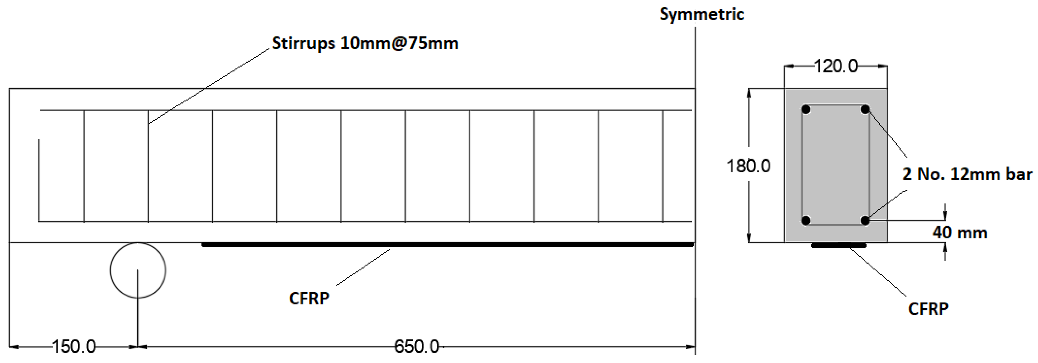
Figure 2.
Specimen fabrication.
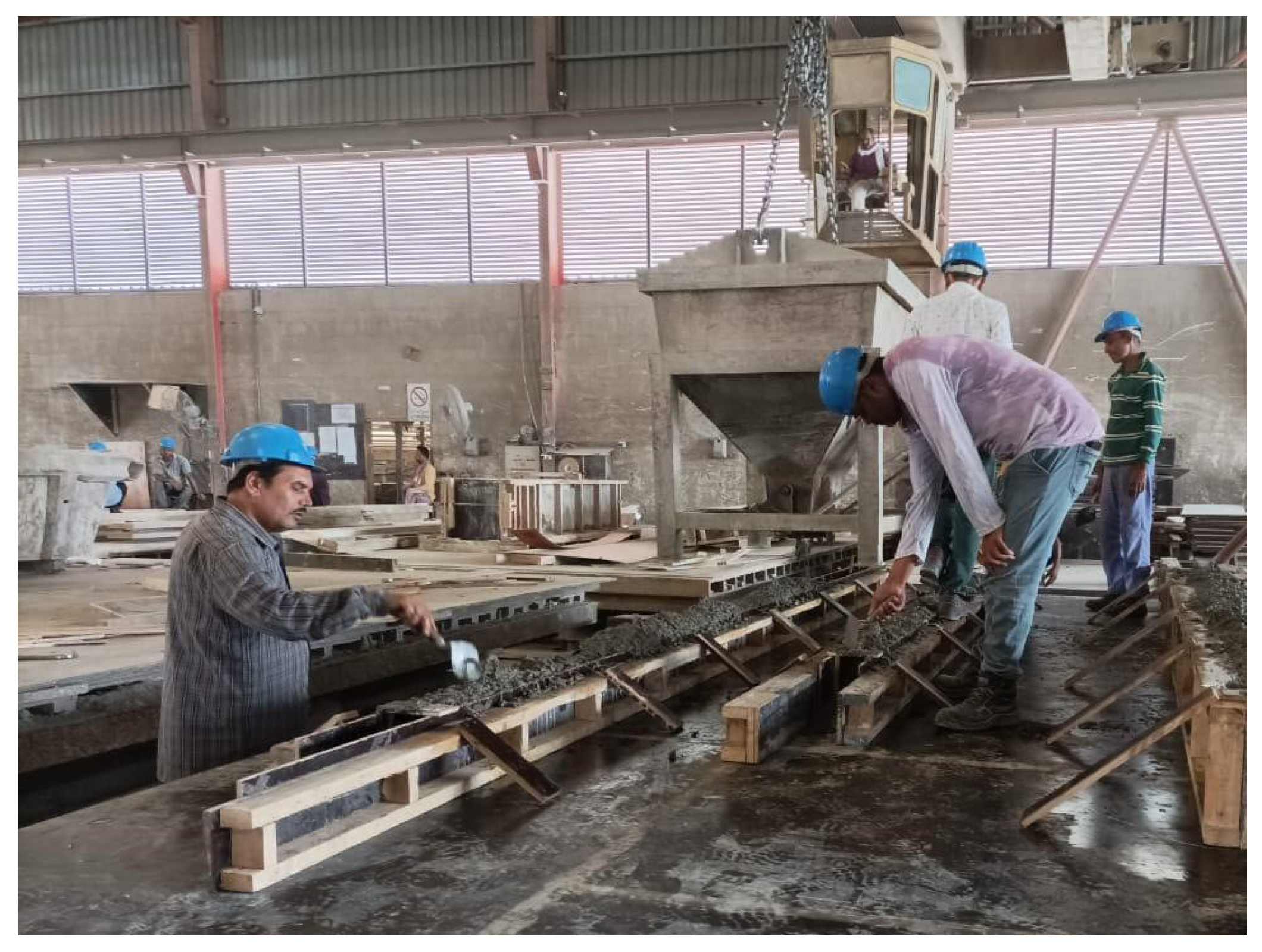
Figure 3.
Cutting grooves.
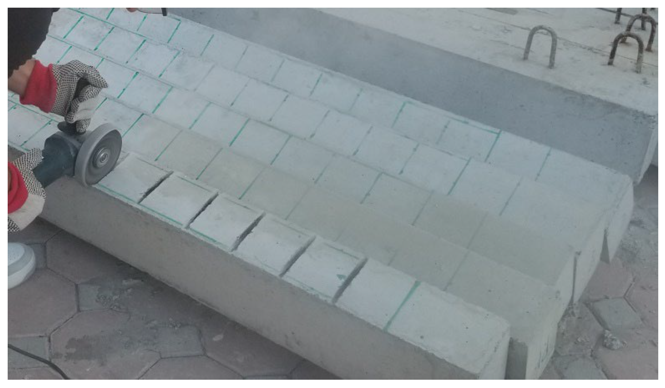
Figure 4.
Strengthening of specimens.
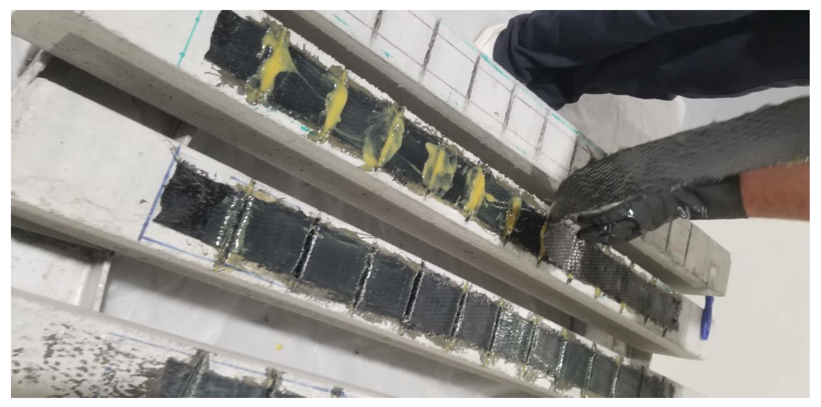
Figure 5.
Holes for anchoring of concrete cover.
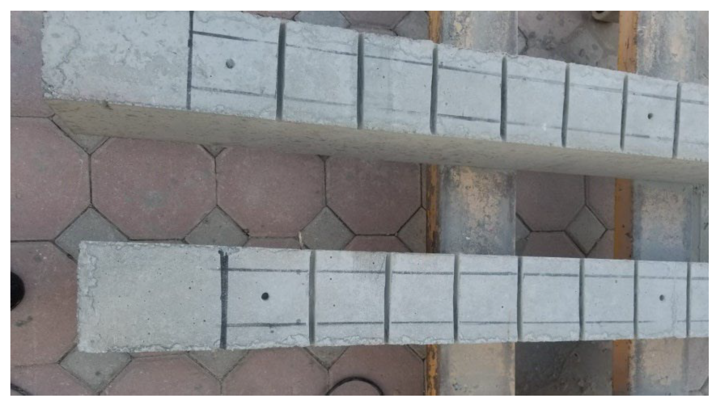
Figure 6.
Cured specimens with strain gauges.
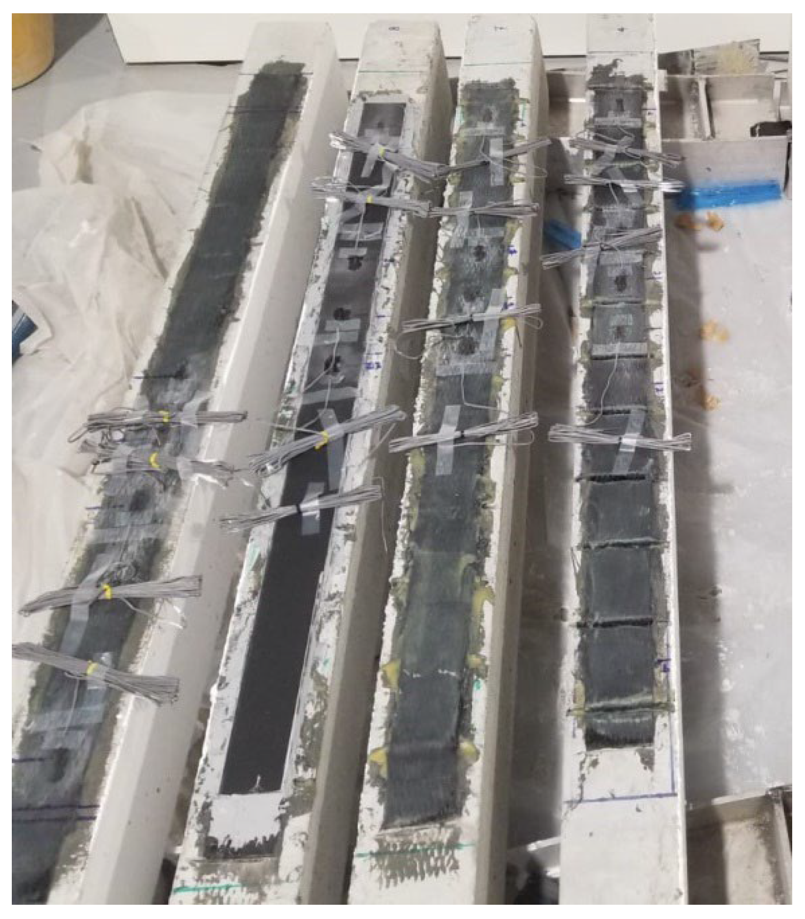
Figure 7.
Test setup of the specimens.
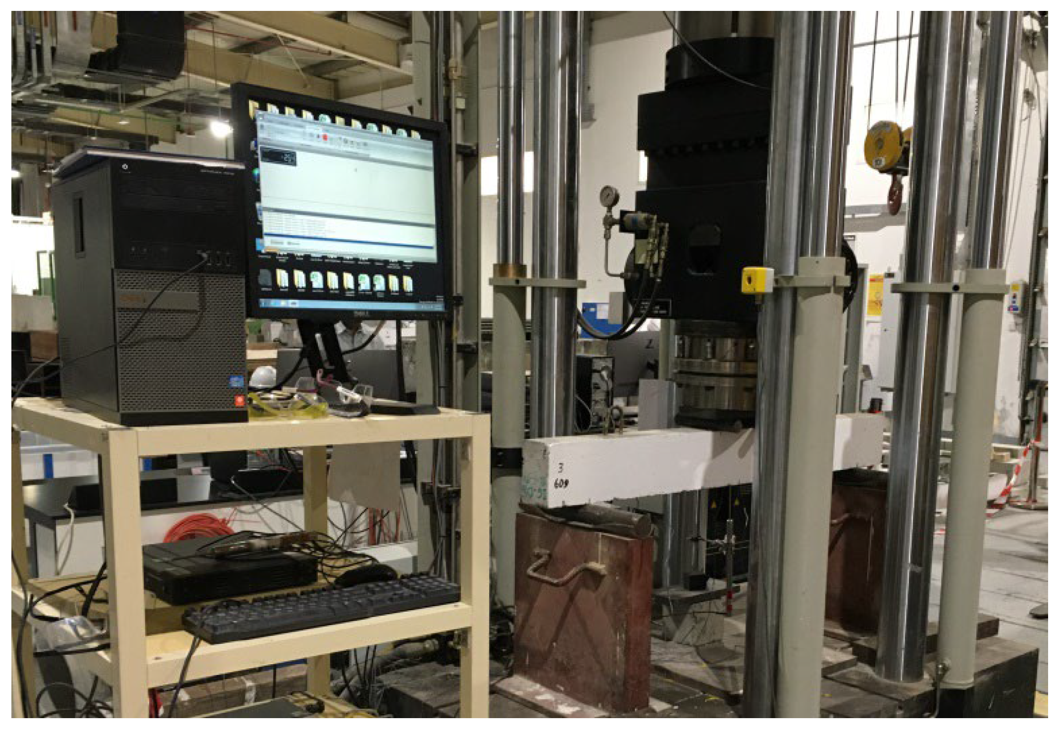
Figure 8.
Mode of failure of B2.
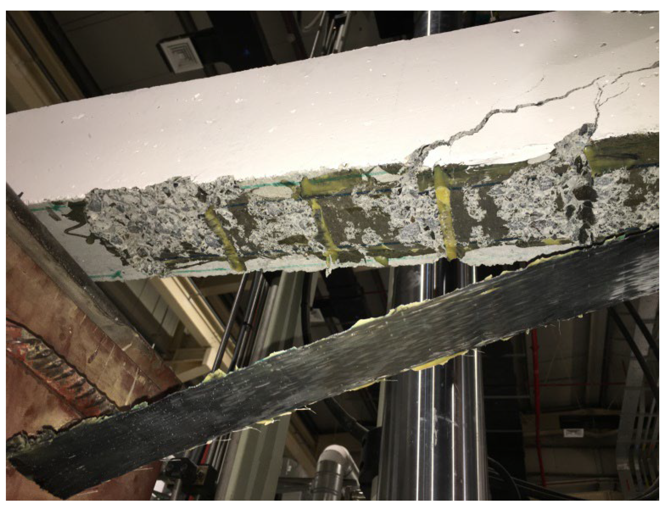
Figure 9.
Load displacement curves of B2 and RB.
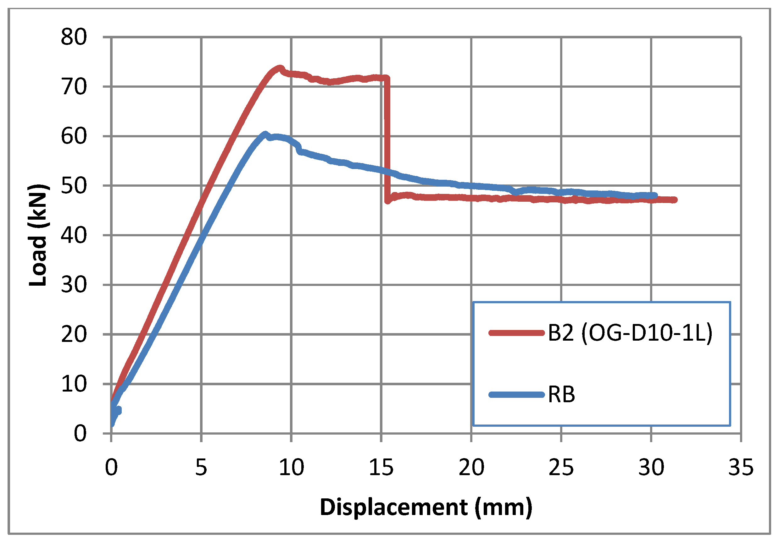
Figure 10.
Load-displacement plot of specimens B3, B4, and RB.
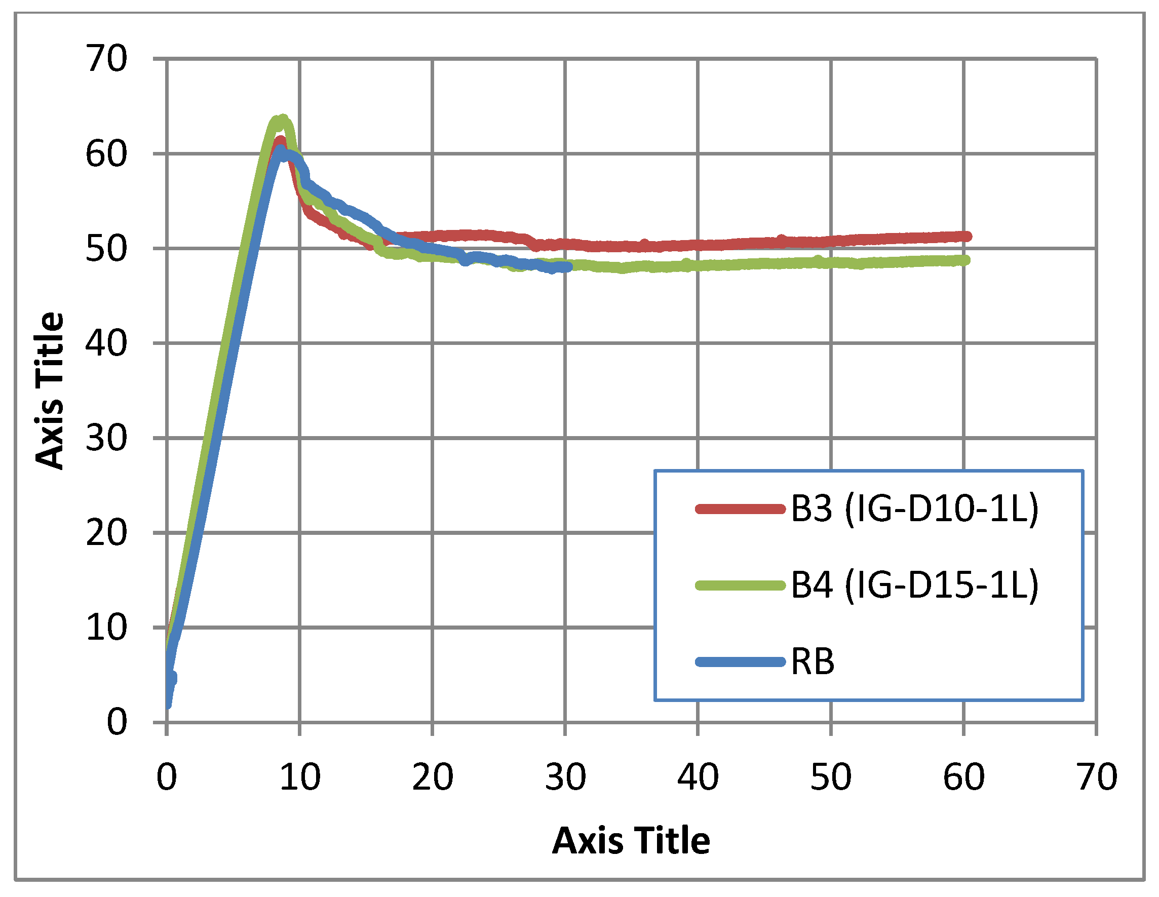
Figure 11.
Failure mode of B3.
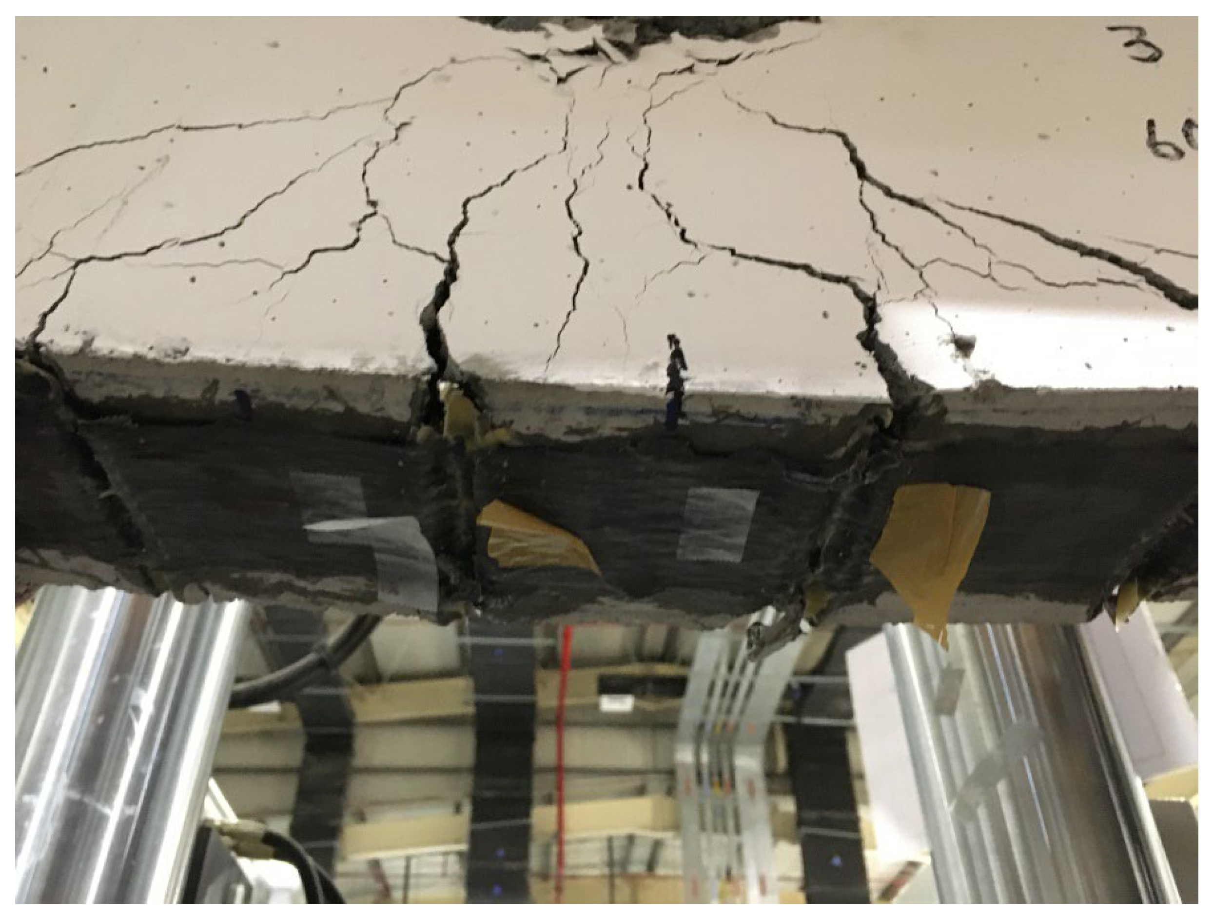
Figure 12.
load-displacement curves of B5 and RB.
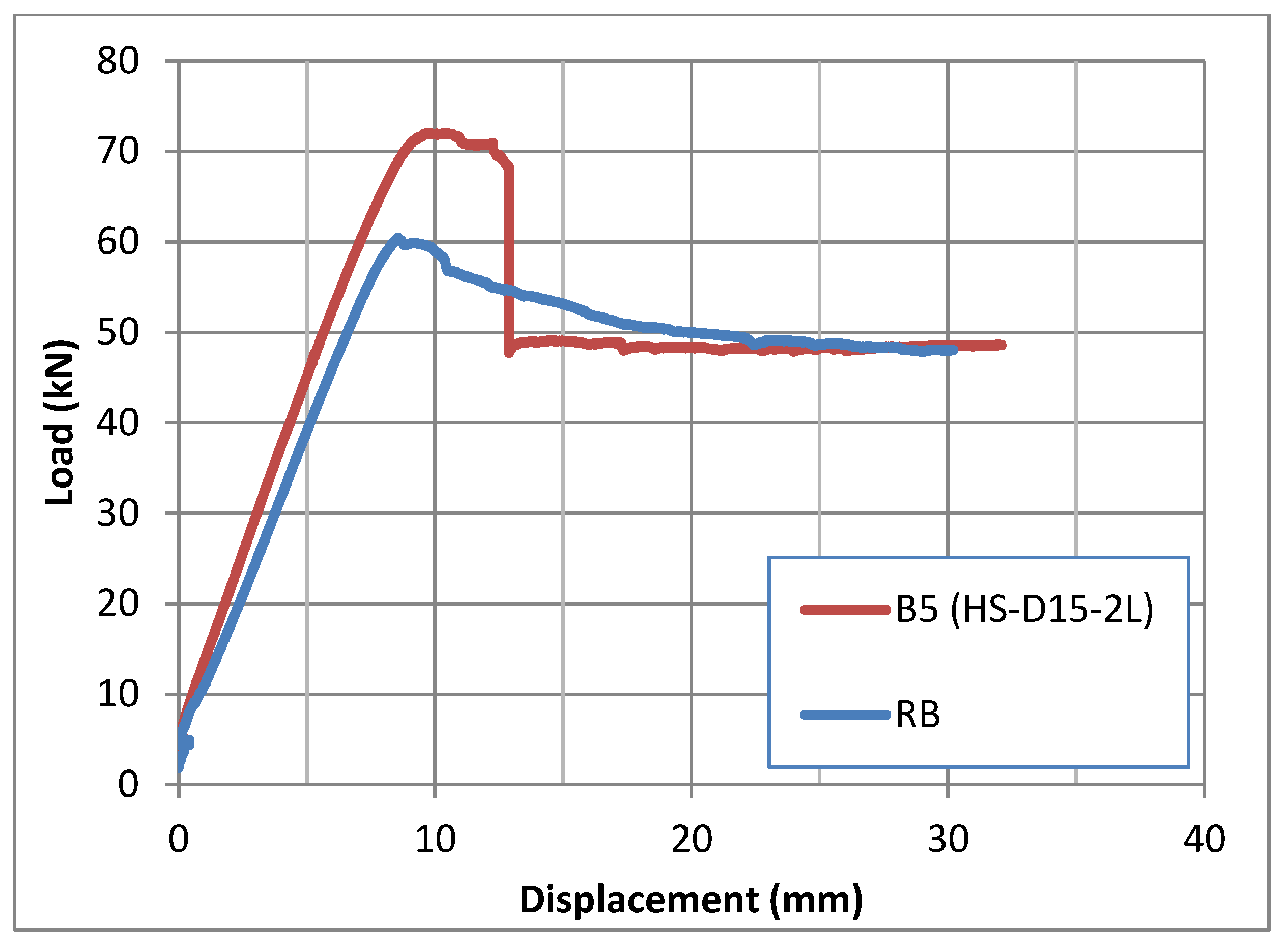
Figure 13.
Failure mode of B5.
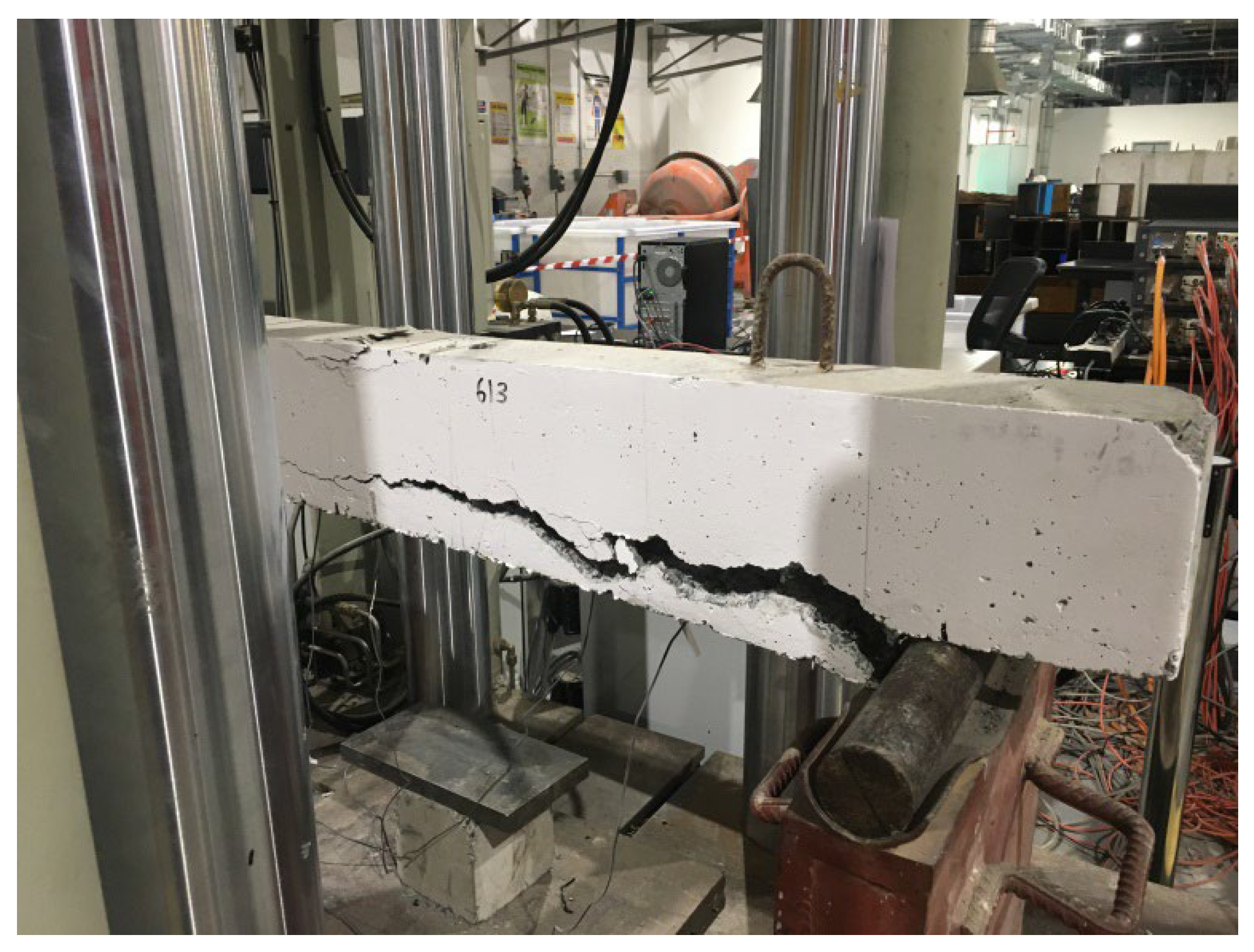
Figure 14.
load versus displacement of B2, B6, B7, and RB.
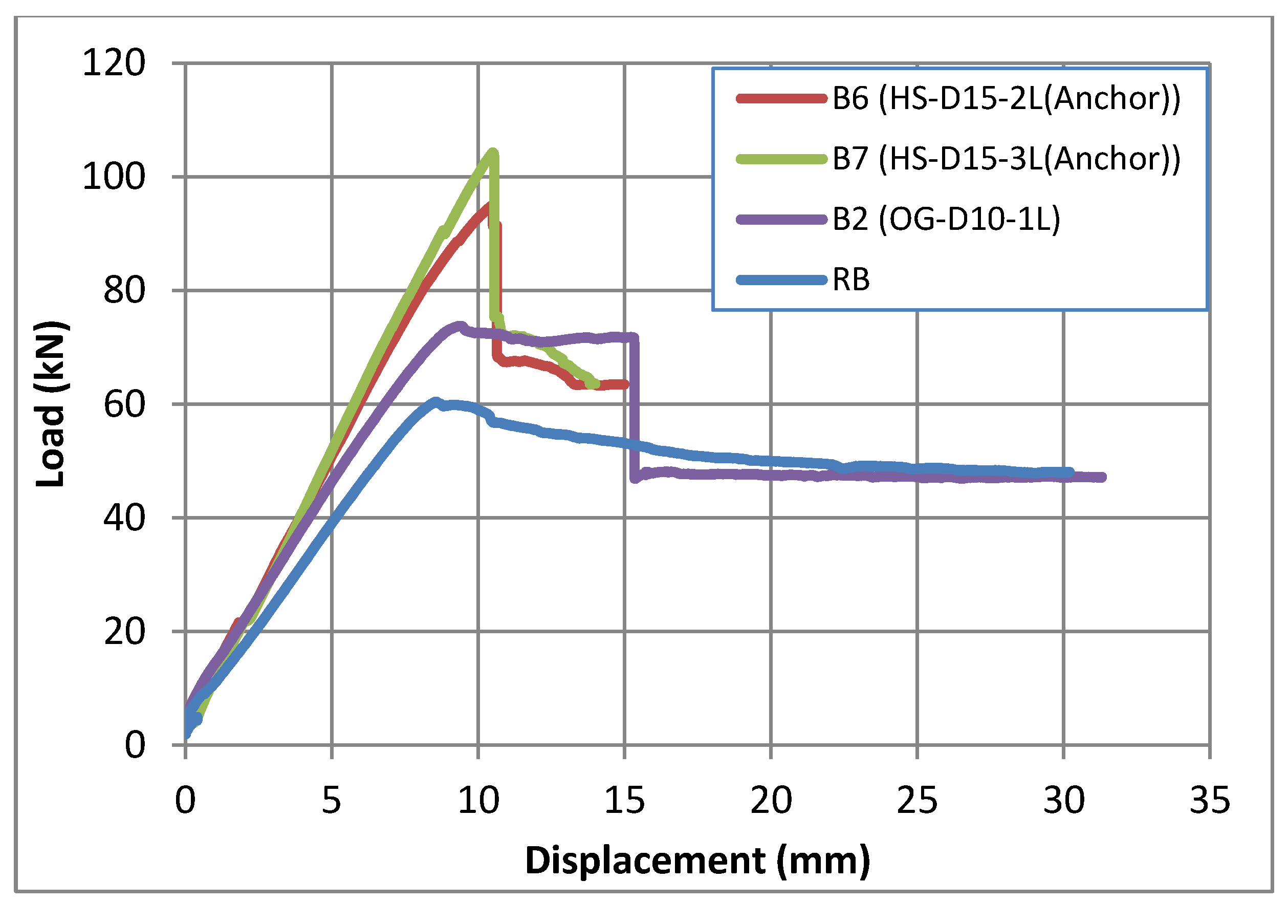
Figure 15.
Failure mode of B6.
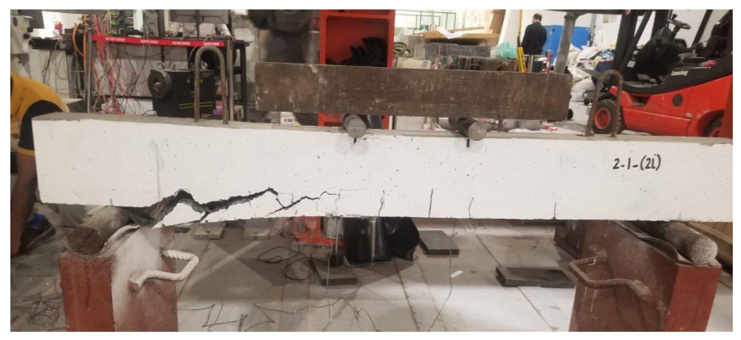
Figure 16.
Strain variation.
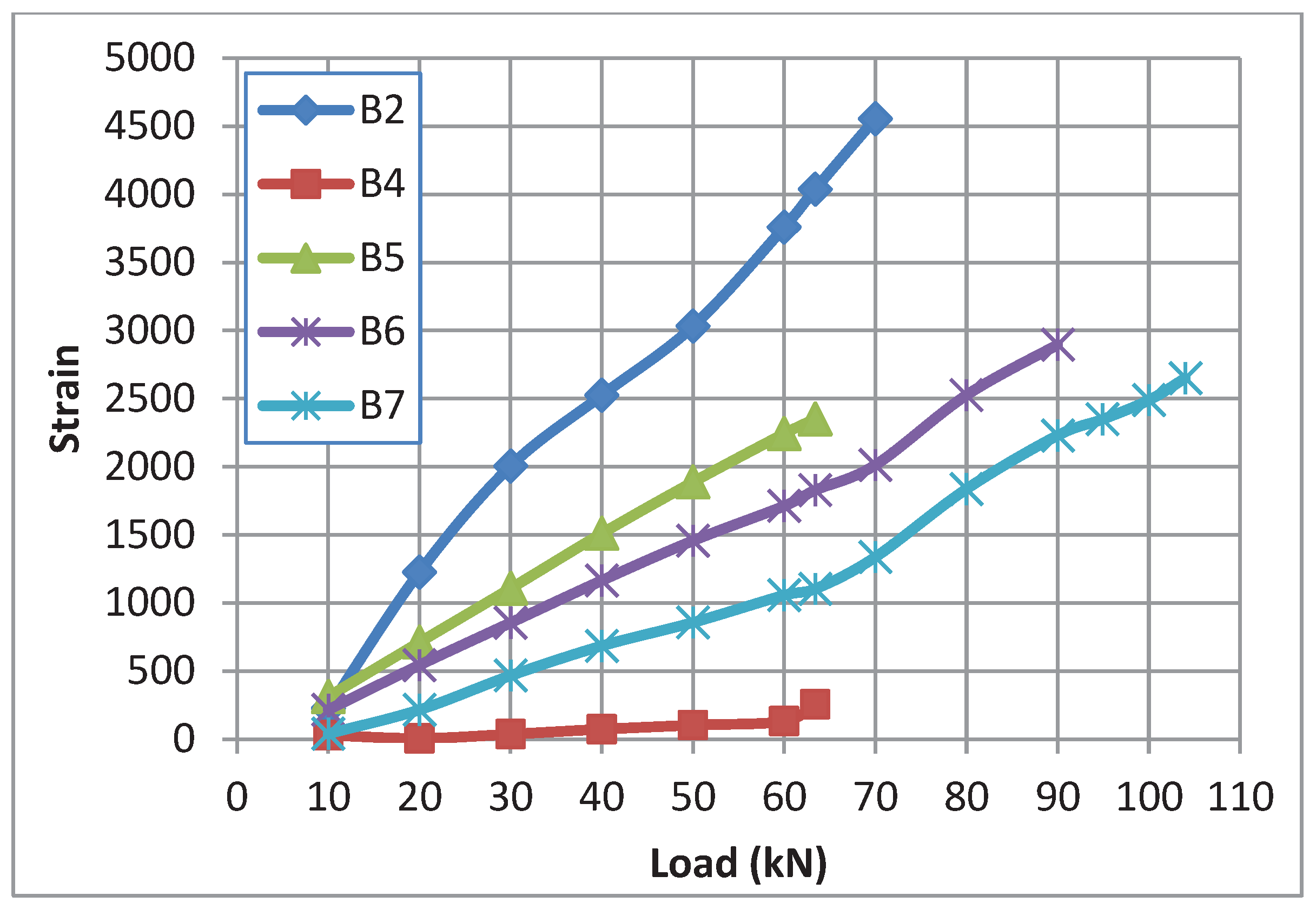

Table 1.
Specimen details.
| Beam No. | Designation | Groove depth (mm) | Groove width (mm) | Distance between grooves (mm) |
|---|---|---|---|---|
| B1 | RB | - | - | - |
| B2 | OG-D10-iL | - | - | 100 |
| B3 | IG-D10-1L | 10 | 8 | 100 |
| B4 | IG-D15-1L | 10 | 8 | 100 |
| B5 | HS-D15-2L | 15 | 8 | 100 |
| B6 | HS-D15-2L(Anchor) | 15 | 8 | 100 |
| B7 | HS-D15-3L(Anchor) | 15 | 8 | 100 |
| R: Reference, OG: Over groove, IG: Inside Groove, D: Groove depth, L: layers, HS: Hybrid system | ||||
Table 2.
Specifications of CFRP fabric [45].
Table 2.
Specifications of CFRP fabric [45].
| Material | Thickness (mm) |
Tensile Strength (MPa) | Modulus of Elasticity (GPa) | Elongation at break (%) |
|---|---|---|---|---|
| CFRP fabric | 0.219 | 4900 | 252 | 2 |
Table 3.
Concrete properties.
| Material | Dimensions (mm) |
Compressive Strength (MPa) | Tensile Strength (MPa) | Modulus of Elasticity (MPa) |
|---|---|---|---|---|
| Concrete | 200 heights × 100 diameter | 42 | 3.64 | 25,900 |
Table 4.
Adhesive properties as per manufacturer data sheet [45].
Table 4.
Adhesive properties as per manufacturer data sheet [45].
| Adhesive | Compressive Strength (MPa) | Tensile Strength (MPa) | Modulus of Elasticity (MPa) |
|---|---|---|---|
| MapeWrap-31 | 70 | 40 | >3001 |
Table 5.
Test results and mode of failure of the specimens.
| Beam No. | Designations | Groove depth mm | Groove width mm | Ultimate Load kN | Failure mode |
|---|---|---|---|---|---|
| B1 | RB | - | - | 60.42 | bending |
| B2 | OG-D10-iL | 10 | 8 | 73.76 | Delamination at Fiber end |
| B3 | IG-D10-1L | 10 | 8 | 61.35 | bending |
| B4 | IG-D15-1L | 15 | 8 | 65.35 | bending |
| B5 | HS-D15-2L | 15 | 8 | 72.00 | Separation of concrete cover |
| B6 | HS-D15-2L(Anchor) | 15 | 8 | 94.93 | Separation of concrete cover |
| B7 | HS-D15-3L(Anchor) | 15 | 8 | 104.27 | Separation of concrete cover |
| R: Reference, OG: Over groove, IG: Inside Groove, D: Groove depth, L: layers, HS: Hybrid system, | |||||
Disclaimer/Publisher’s Note: The statements, opinions and data contained in all publications are solely those of the individual author(s) and contributor(s) and not of MDPI and/or the editor(s). MDPI and/or the editor(s) disclaim responsibility for any injury to people or property resulting from any ideas, methods, instructions or products referred to in the content. |
© 2025 by the authors. Licensee MDPI, Basel, Switzerland. This article is an open access article distributed under the terms and conditions of the Creative Commons Attribution (CC BY) license (http://creativecommons.org/licenses/by/4.0/).
Copyright: This open access article is published under a Creative Commons CC BY 4.0 license, which permit the free download, distribution, and reuse, provided that the author and preprint are cited in any reuse.


