
Submitted:
29 May 2025
Posted:
29 May 2025
You are already at the latest version
Abstract
This study proposes a simple yet versatile microfluidic strategy for fabricating monodisperse alginate hydrogel microspheres using a symmetric flow-focusing device. The system integrates three key innovations: (1) Cost-effective mold fabrication: A paper-based positive master replaces conventional SU-8 photoresist, significantly simplifying device prototyping; (2) Surfactant-free droplet generation: Alginate hydrogel droplets are formed at the first flow-focusing junction without requiring interfacial stabilizers; (3) In situ solidification with coalescence suppression: Acetic acid-infused corn oil is introduced at the adjacent junction, simultaneously triggering ionic crosslinking of alginate via pH reduction while preventing droplet aggregation. Notably, the hydrogel microspheres can be efficiently harvested through oscillatory aqueous phase separation, removing post-fabrication washing steps (typically 6-8 cycles for surfactant and oil removal). This integrated approach demonstrates exceptional advantages in fabrication simplicity, process scalability, and operational robustness for high-throughput hydrogel microsphere production.
Keywords:
hydrogel microsphere
; microfluidics
; demulsifier-Free
; surfactant-free
; droplet formation
; non-lithography
1. Introduction
Alginate hydrogel microbeads have found extensive applications, spanning from academic research to industrial production [1,2]. Traditional mass-production methods of alginate microcapsules commonly rely on mechanical stirring or external gelation-based mixing [3,4,5]. Nevertheless, these techniques frequently yield microcapsules with diverse morphologies and sizes, hampering their seamless application across various fields. In contrast, microfluidic techniques present an alternative route for generating monodisperse droplets with precisely tailored morphologies and dimensions [6,7,8,9], thus surmounting the technological hurdles associated with the above-mentioned applications. The chaotic mixing of alginate solution and calcium ions at the T-junction in microfluidic devices can cause clogging. This is because the rapid cross - linking of microgels occurs in narrow channels [7]. To overcome this, calcium carbonate (CaCO₃) nanoparticles have been used to produce uniformly-sized microgels. Under acidic conditions, water-insoluble Ca²⁺ can be released into the alginate solution post–emulsification [6]. However, the heterogeneous distribution of large CaCO₃ particles poses challenges, resulting in non-uniform cross-linking within the formed microbeads. To address this, Weitz’s group demonstrated the use of a water-soluble calcium-ethylenediaminetetraacetic acid (calcium-EDTA) complex to regulate calcium ion delivery. This approach enables excellent homogeneity in microgel formation without causing non-uniform gelation [8,9,10]. The fabrication of cross-linked microgels is a multi-stage process, demanding significant labour. Lin’s group developed an integrated microfluidic system consisting of two separate chips. This system uses a calcium-EDTA complex as a precursor to produce high-quality hydrogel microbeads. It also facilitates the online formation and automatic cross-linking of microbeads for three-dimensional cell culture [11]. The Moulton group demonstrated a substantial enhancement in alginate-based biomolecule encapsulation efficiency by optimizing flow dynamics and polymer concentration ratios on a conventional microfluidic platform. Their approach utilized a surfactant-demulsifier co-stabilization system (Picosurf™/C8F15CH2OH) to achieve interfacial stability under physiologically relevant conditions, thereby enabling precise microbead formation while preserving biocompatibility [12]. However, similar studies in this field predominantly rely on costly chemical agents, including perfluorinated polyether-polyethylene glycol (PFPE-PEG) [11,12,13,14], Picosurf™ [12], neat 008-fluorosurfactants [13], Krytox–PEG–Krytox triblock copolymers [15], span 80 [16,17,18,19,20,21], polyglycerol polyricinoleate (PGPR) surfactants [22] for monodisperse emulsion generation, and 1H,1H,2H,2H-perfluoro-1-octanol (PFO) [11,12,13,14,15,16,17] for demulsification. Notably, few methodologies have addressed the critical need for cost-effective, low-reagent-consumption platforms compatible with resource-limited settings.
In this study, we present a novel approach for fabricating homogeneous alginate microbeads using a symmetric flow-focusing configuration integrated within a PDMS (polydimethylsiloxane) microfluidic device. This innovative methodology addresses several critical challenges: (i) A paper-based positive master replaces conventional SU-8 photoresist, significantly simplifying device prototyping. (ii) The implementation of pure oil as the continuous phase enables economical generation of monodisperse alginate hydrogel droplets, effectively eliminating the necessity for surfactant additives. (iii) The incorporation of acetic acid significantly mitigates droplet coalescence in the oil medium, thereby facilitating scalable production of uniform microbeads. (ⅳ) The developed process allows for efficient separation of microspheres from corn oil through an oscillatory aqueous phase, completely removing the dependency on demulsifier phases.
2. Materials and Methods
2.1. Materials
All chemicals and materials were obtained from commercial sources: corn oil (Yihai Kerry Arawana, China), EDTA disodium salt (Beyotime Biotechnology, China), PDMS and initiators (Dow Corning, USA), calcium chloride (Xilong Scientific, China), acetic acid (Chron Chemicals, China), and PTFE tubes (0.35 mm ID, Woer Co., China).
2.2. The Fabrication of the PDMS Microfluidic Device
The fabrication process of the PDMS-based microfluidic device was carried out by adopting a straightforward and cost-efficient method, which was elaborated in our previous research work [23]. A symmetric flow-focusing geometry for the positive master was designed with the aid of AutoCAD software, as illustrated in Figure 1(a). The distance between the double flow-focusing junctions was set to 10 mm, while the width of all the microchannels was maintained at 500 µm. Self-adhesive paper with a thickness of 900 µm, sourced from Chengdu, China, was manually affixed to a glass slide. Instead of using a CNC (Computerized Numerical Control) machine, a laser machine (C180Ⅱ, GCC LaserPro, USA) was utilized to fabricate a patterned positive master from the aforementioned self-adhesive paper, as shown in Figure 1(b). After the fabrication process, the entire cross-sectional dimensions of the positive master were 900×350 µm (height×width), as depicted in Figure 1(C). Subsequently, a degassed mixture of PDMS and initiators in a ratio of 10:1 was poured onto the positive master and cured at 55℃ for 90 minutes. After the solidification process was fully completed, the PDMS slab was carefully peeled off from the master, cut into the desired shape, and holes were punched. Finally, after being treated in oxygen plasma (TS-SY05, tonsontec, China), the PDMS slab was hermetically sealed onto a glass substrate to finish the microfluidic device, as shown in Figure 1(d).
2.3. Characterization of Hydrogel Microspheres
The flow rates for corn oil, calcium-EDTA hydrogel, and acetic oil during the formation of hydrogel microspheres were set to 2 µL/min, 40 µL/min, and 40 µL/min, respectively. After synthesis, the microspheres were separated, washed with deionized water, and subsequently frozen. They were then subjected to vacuum drying at −25 °C for 30 seconds in a Phenom Pharos G2 Desktop FEG-SEM (Thermo Fisher Scientific, USA). The surface morphology of the microspheres was analyzed using scanning electron microscopy (SEM) at magnifications ranging from 180× to 1500×, enabling high-resolution characterization of both surface features and microstructural details.
3. Results and Discussion
3.1. Formation of Hydrogel Microsphere
In our proposal work, the paper-based master fabrication strategy fundamentally alters cost structures by three aspects: (ⅰ)Eliminating cleanroom requirements; (ⅱ)Reducing mold material costs by 92% compared to SU-8 lithography; (ⅲ)Enabling rapid prototyping (≤2 hr per device vs. 24+ hr for PDMS devices). Figure 1. illustrates the prototyping of the microfluidic device used for the formation of alginate microspheres. In our experiment, a calcium-EDTA complex dissolved in Na-alginate solution served as the dispersed phase, while corn oil (without surfactant) functioned as the continuous phase, as shown in Figure 1(a). Droplets were generated at one of the flow-focusing microfluidic devices, where the other flow-focusing junction was designed to solidify the droplet, as it depicted in Figure 1(e). The corn oil, devoid of surfactant, effectively produced droplets of the Na-alginate solution containing the calcium-EDTA complex, resulting in an emulsion with a narrow distribution in droplet size.
At another flow-focusing junction downstream, acetic acid (2% w/w) dissolved in corn oil was introduced and mixed with the stream of monodisperse droplets. The H+ ions from the acidic oil readily diffused into the aqueous Na-alginate droplets. Notably, the acidic oil was mixed with the corn oil downstream to stabilize the Na-alginate droplets against coalescence [24], thereby preserving the homogeneous size of the spherical alginate microspheres.
3.2. Separation of Hydrogel Microsphere
Figure 2a visually depicts the hydrogel microspheres coalescence without any surfactant in continuous oil phase, which were generated using single flow-focusing microfluidic device. To isolate the hydrogel microspheres from the corn oil, the emulsions were transferred into a petri dish containing an aqueous solution. The separation of the hydrogel microspheres from the oil phase was initially achieved by placing the petri dish on a micro-plate shaker (QB-8001, Mini shaker, China) and subjecting it to an oscillating motion at 300 rpm/min. Notably, these microspheres demonstrated a remarkable ability to migrate rapidly from the oil phase to the aqueous phase in this symmetry flow-focusing microfluidic system. This migration not only facilitated the efficient transfer of the microspheres but also instantaneously halted the gelation reaction, as evidenced in Figure 2b. Once the microspheres settled at the bottom of the aqueous solution, the excess oil, which floated on the surface of the aqueous phase, was easily removed using an aspirator without the need for a demulsifier. Remarkably, the entire extraction process was completed in just 5 minutes, with minimal cost, highlighting its efficiency and economic viability, as summarized in Table 1.
In the preparation step, the calcium-EDTA complex was meticulously prepared by combining equal volumes of an aqueous calcium chloride solution (100 mM) and a disodium-EDTA solution (100 mM). The pH of the resulting mixture was carefully adjusted to 7.2 to ensure the high stability of the complex. As illustrated in Figure 3, the size of the hydrogel microspheres could be precisely controlled by modulating the flow rate of the continuous phase, specifically corn oil. Under the experimental conditions where the calcium-EDTA complex concentration in the alginate medium was fixed at 2 wt% and the corn oil contained 2% w/w acetic acid, spherical hydrogel microspheres with diameters ranging from 135±2.7 µm to 182±4.12 µm were successfully fabricated by varying the continuous phase flow rate, as shown in Figure 3a-f. During the experiments, the flow rate of the alginate solution was held constant at 3 µL/min, while the flow rate of the corn oil was systematically increased from 20 µL/min, 25µL/min, 30µL/min, and 40 µL/min, respectively. Notably, the flow rate of the acidic oil phase was accompanied with the same flow rate of corn oil at 20 µL/min, 25µL/min, 30µL/min, and 40 µL/min, respectively. As clearly demonstrated in Figure 4a-f, this adjustment resulted in a significant reduction in emulsion diameter, highlighting a direct correlation between the corn oil flow rate and the size of the hydrogel microspheres. The synthesized microspheres demonstrated remarkably low size polydispersity, as evidenced by an exceptional coefficient of variation (C.V.) below 5%. This surfactant- and demulsifier-free fabrication strategy achieves significant cost efficiencies through two synergistic mechanisms: 1) Elimination of conventional post-synthesis purification processes (typically requiring 6-8 washing cycles for surfactant and oil residue removal), and 2) Direct omission of interfacial stabilizers, which conventionally account for 65-90% of total production costs in traditional methodologies.
3.3. Surface Morphologies and Microstructures of Hydrogel Microsphere
Figure 5 shows representative SEM images of the microspheres at magnifications ranging from 180× to 1500×. The surface morphology reveals distinct roughness and uniformity across the microspheres. At higher magnifications (Figure 5a–d), high-resolution imaging highlights numerous porous regions on the surfaces. This porous architecture facilitates rapid permeation of the solution and H⁺ ions into the microspheres, enabling complete solidification within minutes.
4. Conclusions
In summary, we present an innovative two-step microfluidic approach for fabricating monodisperse alginate hydrogel microspheres with exceptional spherical uniformity. By employing the calcium-EDTA complex as a crosslinking precursor and utilizing pH-triggered Ca²⁺ ion release, we achieve consistent and homogeneous gelation of the microspheres. This method offers the distinct advantage of enabling precise control over the physical properties of the microgels. Through careful adjustment of the crosslinker concentration and alginate chain characteristics, the properties of the microspheres can be finely tailored to meet specific requirements. Furthermore, our results demonstrate that this process is not only cost-effective but also highly adaptable for use in resource-limited settings.
Acknowledgments
The research findings presented in this work were funded by multiple sources. These include the Scientific Research Foundation of the Hunan Provincial Education Department, China (Grant Nos. 23B0725 and 22A0549), the Hunan Natural Science Foundation, China (Grant Nos. 2025JJ70487, 2025JJ70433, 2022JJ30467 and 2022JJ50312), the Research Foundation of Huaihua University, China (Grant Nos. HHUY2021-01 and HHUY2021-02), the Foundation of Hunan Double First-rate Discipline Construction Projects (Grant No. SWGC-04), and the National Training Program for Undergraduate Innovation and Entrepreneurship (Grant No. S202110548078). We are grateful of Professor Hongbo Li for discussions and advice for improving this manuscript.
Conflicts of Interest
There are no conflicts to declare.
References
- Mou, C.-L.; Deng, Q.-Z.; Hu, J.-X.; Wang, L.-Y.; Deng, H.-B.; Xiao, G.; Zhan, Y. Journal of Colloid and Interface Science 2020, 569, 307–319. [CrossRef] [PubMed]
- Jiang, S.; Jing, H.; Zhuang, Y.; Cui, J.; Fu, Z.; Li, D.; Zhao, C.; Liaqat, U.; Lin, K. Carbohydrate Polymers 2024, 332. [CrossRef] [PubMed]
- Martins, I.M.; Barreiro, M.F.; Coelho, M.; Rodrigues, A.E. Chemical Engineering Journal 2014, 245, 191–200. [CrossRef]
- Morimoto, Y.; Onuki, M.; Takeuchi, S. Advanced Healthcare Materials 2017, 6(13). [CrossRef]
- Somo, S.I.; Langert, K.; Yang, C.-Y.; Vaicik, M.K.; Ibarra, V.; Appel, A.A.; Akar, B.; Cheng, M.-H.; Brey, E.M. Acta Biomaterialia 2018, 65, 53–65. [CrossRef]
- Tan, W.-H.; Takeuchi, S. Advanced Materials 2007, 19, 2696-+. [CrossRef]
- Choi, C.-H.; Jung, J.-H.; Rhee, Y.W.; Kim, D.-P.; Shim, S.-E.; Lee, C.-S. Biomedical Microdevices 2007, 9, 855–862. [CrossRef]
- Utech, S.; Prodanovic, R.; Mao, A.S.; Ostafe, R.; Mooney, D.J.; Weitz, D.A. Advanced Healthcare Materials 2015, 4, 1628–1633. [CrossRef]
- Rojek, K.O.; Cwiklinska, M.; Kuczak, J.; Guzowski, J. Chemical Reviews 2022, 122, 16839–16909. [CrossRef]
- Chen, Q.; Utech, S.; Chen, D.; Prodanovic, R.; Lin, J.-M.; Weitz, D.A. Lab on a Chip 2016, 16, 1346–1349. [CrossRef]
- Zheng, Y.; Wu, Z.; Khan, M.; Mao, S.; Manibalan, K.; Li, N.; Lin, J.-M.; Lin, L. Analytical Chemistry 2019, 91, 12283–12289. [CrossRef] [PubMed]
- Aguilar, L.M.C.; Duchi, S.; Onofrillo, C.; O’Connell, C.D.; Di Bella, C.; Moulton, S.E. Journal of Colloid and Interface Science 2021, 587, 240–251. [CrossRef] [PubMed]
- Zhou, X.; Zhu, L.; Li, W.; Liu, Q. Analytical Methods 2022, 14(12), 1181–1186. [CrossRef]
- Li, Y.; Yao, H.; Chen, S.; Xu, N.; Lin, J.-M. Analytical Chemistry 2023, 95(2), 1402–1408.
- Li, B.; Zhang, L.; Yin, Y.; Chen, A.; Seo, B.R.; Lou, J.; Mooney, D.J.; Weitz, D.A. Matter 2024, 7(10).
- Qiao, S.; Chen, W.; Zheng, X.; Ma, L. International Journal of Biological Macromolecules 2024, 254.
- Jiang, S.; Jing, H.; Zhuang, Y.; Cui, J.; Fu, Z.; Li, D.; Zhao, C.; Liaqat, U.; Lin, K. Carbohydrate Polymers 2024, 332. [CrossRef] [PubMed]
- Dong, J.; Lang, Y.; He, J.; Cui, J.; Liu, X.; Yuan, H.; Li, L.; Zhou, M.; Wang, S. Biomaterials 2025, 317. [CrossRef]
- Chen, S.; Shahar, T.; Cohen, S. Rsc Advances 2024, 14(44), 32021–32028. [CrossRef]
- Cheng, Y.; Li, B.; Wang, J.; Wang, Y.; Wang, L.; Wei, M.; Wang, Y.; Chen, Z.; Zhao, G. Langmuir 2025, 41(13), 8985–8997. [CrossRef]
- Tran, D.T.; Galeai, F. M.; Nguyen, N.-K.; Roshan, U.; Yadav, A.S.; Sreejith, K.R.; Nguyen, N.-T. Chemnanomat 2025, 11(3).
- Marburger, J.; Vladisavljevic, G. T.; Leister, N. Colloids and Surfaces a-Physicochemical and Engineering Aspects 2025, 714.
- Zhou, Z.; Chen, D.; Wang, X.; Jiang, J. Micromachines 2017, 8(10).
- Jeong, Y.; Irudayaraj, J. Chemical Communications 2022, 58, 8584–8587. [CrossRef]
Figure 1.
The microfluidic formation of homogeneously sized alginate microspheres encompasses several crucial components:(a) A symmetric flow-focusing pattern of the microfluidic device, designed using AutoCAD software. (b)Multiple symmetric flow -focusing patterns on self-adhere paper, printed via laser engraving. (c)Positive paper masters, created after tearing off the complementary parts for PDMS moulding. (d) The prototypes of the PDMS-based microfluidic devices. (e) An enlarged illustration of the local flow-focusing structure in (a). (f) A schematic diagram depicting the process of alginate cross-linking. Herein, the introduction of acid at the flow-focusing structure triggers the complete formation of cross-linked microspheres as calcium ions are released from the calcium-EDTA complex solution.
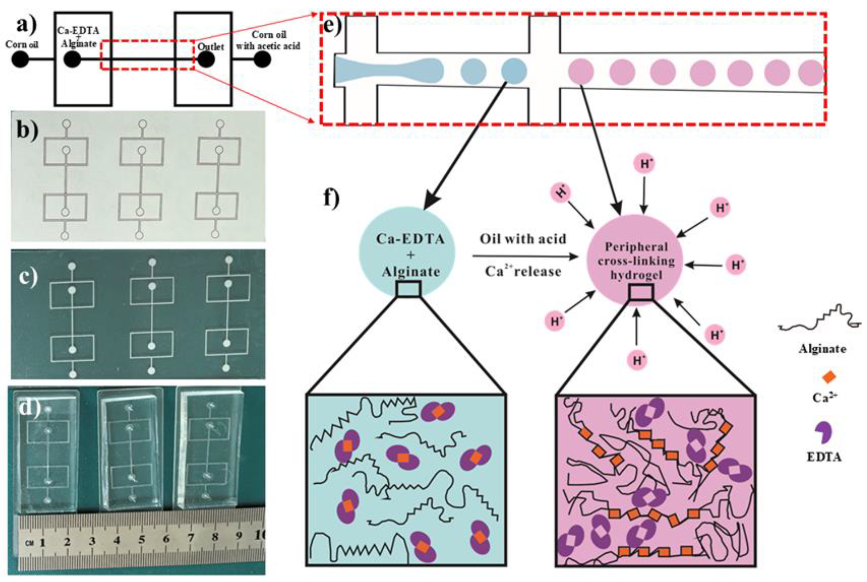
Figure 2.
Microfluidic synthesis of surfactant-free alginate microspheres. (a) Bright-field microscopy image of alginate microspheres generated in a single-channel flow focusing microfluidic device without surfactant. (b) Corresponding microspheres produced via symmetric dual-channel flow-focusing microfluidic emulsification, demonstrating uniform surfactant-free alginate droplet templating. Scale bars: 100 µm (applies to all panels).
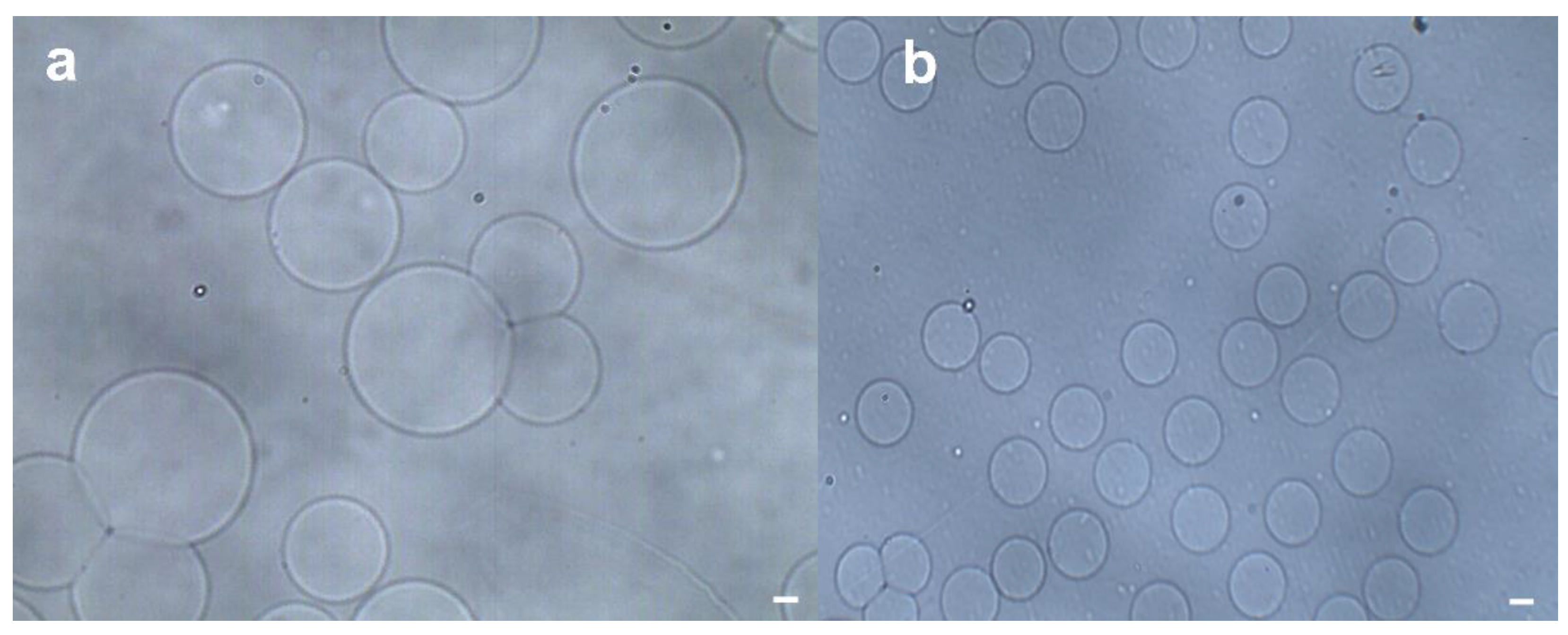
Figure 3.
Phase-contrast microscopic images depicting the alginate microspheres after the demulsification process are presented. In these experimental configurations, the flow rates of the disperse alginate–calcium–EDTA solution were firmly set at 3 µL/min. (a) With regard to the specific microfluidic device, in order to regulate the droplet size, the flow rate of the continuous oil phase was adjusted to 20 µL/min; (b) The flow rate of the continuous oil phase was established at 25 µL/min; (c) The continuous oil phase flowed at a rate of 30 µL/min; (d) The flow rate of the continuous oil phase was maintained at 35 µL/min; (e) The continuous oil phase had a flow rate of 40 µL/min; (f) The flow rate of the continuous oil phase was set at 45 µL/min. The scale bar in the image represents 200 µm.
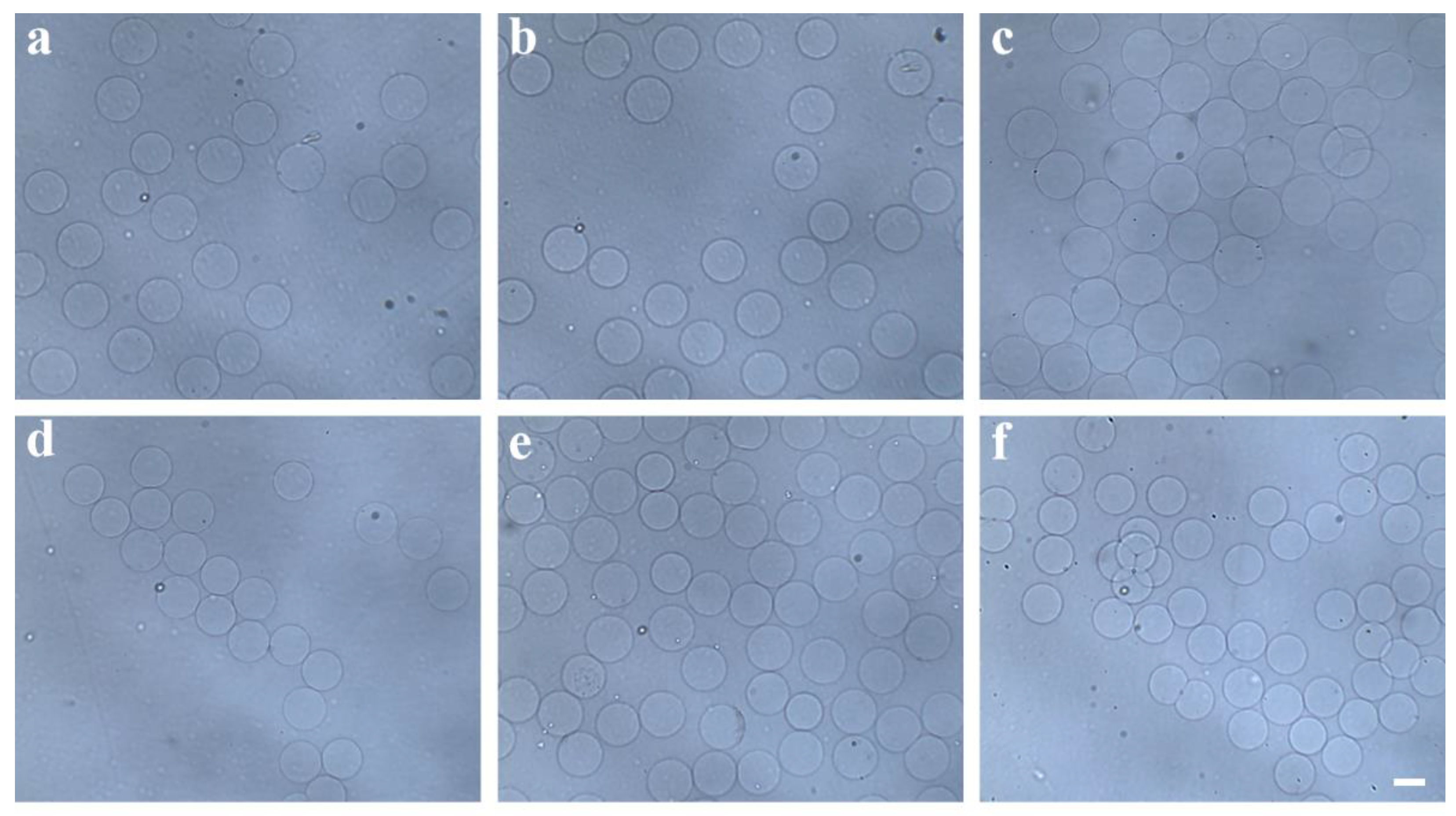
Figure 4.
Size distribution of the alginate hydrogel microspheres shown in (a) to (d) with the constant flow rate of disperse alginate phase 3µL/min, and the varied flow rates of the continuous oil phase from 20 µL/min to 40µL/min, respectively.
Figure 4.
Size distribution of the alginate hydrogel microspheres shown in (a) to (d) with the constant flow rate of disperse alginate phase 3µL/min, and the varied flow rates of the continuous oil phase from 20 µL/min to 40µL/min, respectively.
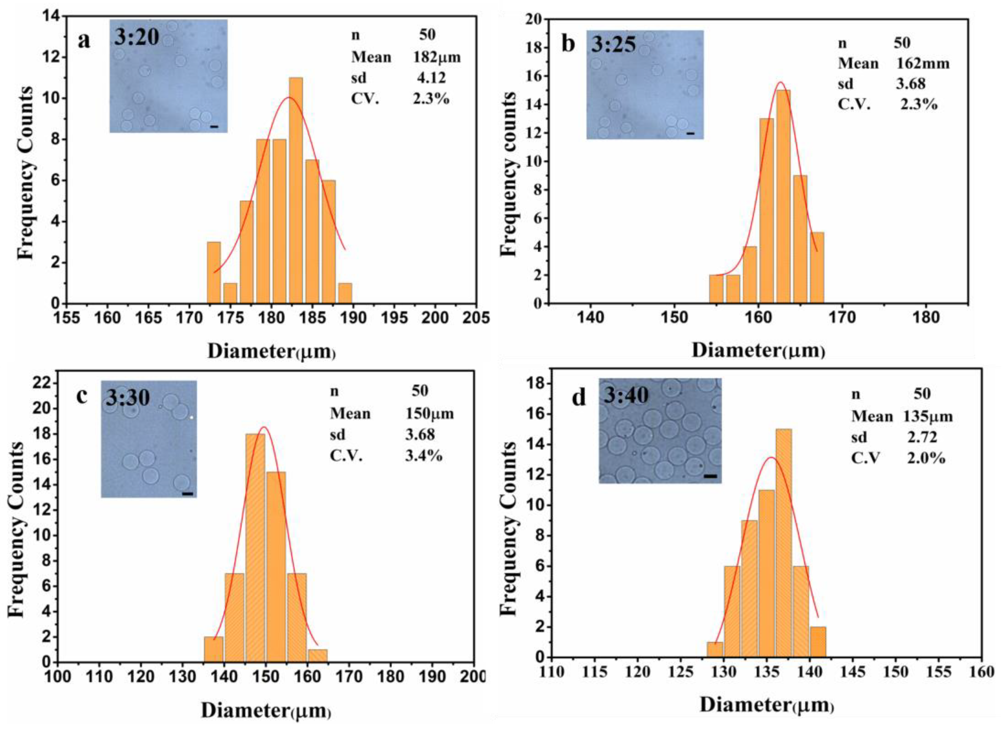
Figure 5.
SEM characterization of alginate hydrogel microspheres synthesized under fixed dispersed-phase flow conditions. (a–d) SEM images of microspheres generated with a dispersed alginate phase flow rate of 2 µL/min and a continuous oil phase flow rate of 30 µL/min. Magnification and scale bars: (a) 180× (scale bar: 100 µm), (b) 430× (scale bar: 40 µm), (c) 1000× (scale bar: 20 µm), (d) 1500× (scale bar: 10 µm).
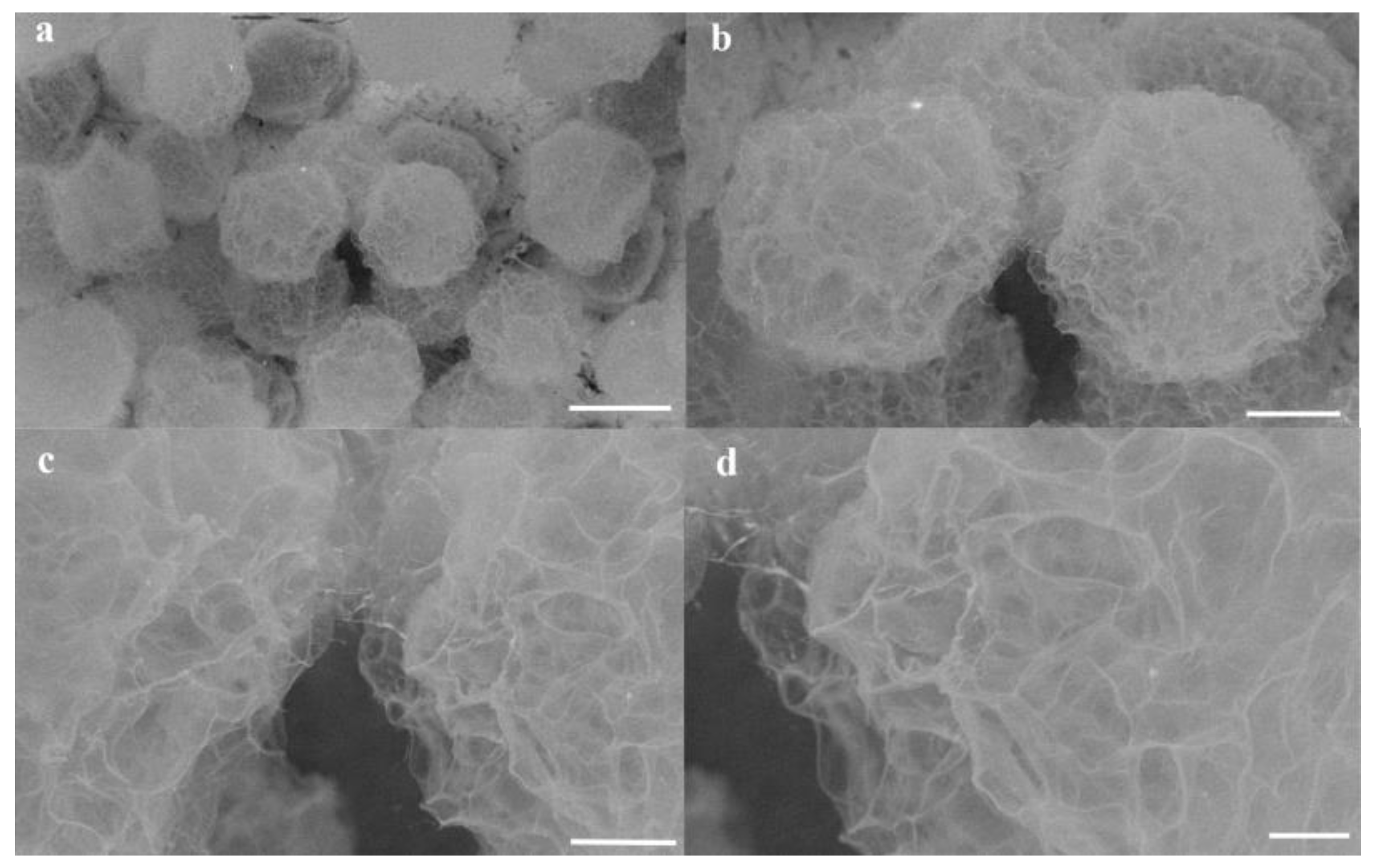

Table 1.
The distinct comparative advantages of the two-stage approach when contrasted with the represent methods.
Table 1.
The distinct comparative advantages of the two-stage approach when contrasted with the represent methods.
| Master | Surfactant | Demulsification | Ref. |
| Glass tube | F-127 | Isopropyl alcohol | 1 |
| SU-8 | Span 80 | PFO | 2,16 |
| SU-8 | Lecithin | Hexane/Hexadecane | 6 |
| SU-8 | PFPE-PEG | PFO | 8,11,14 |
| SU-8 | PicosurfTM | 1H,1H-Perfluorooctan-1-ol | 12 |
| SU-8 | neat 008-uorosurfactant | PFO | 13 |
| SU-8 | Krytox–PEG–Krytox | PFO | 15 |
| Paper | Without addition | Without addition | This work |
SU-8: SU-8 2050 photoresist. F-127: pluronic F-127. PFPE-PEG: perfluorinated polyetherspolyethyleneglycol. PFO: 1H,1H,2H,2H-Perfluoro-1-octanol.
Disclaimer/Publisher’s Note: The statements, opinions and data contained in all publications are solely those of the individual author(s) and contributor(s) and not of MDPI and/or the editor(s). MDPI and/or the editor(s) disclaim responsibility for any injury to people or property resulting from any ideas, methods, instructions or products referred to in the content. |
© 2025 by the authors. Licensee MDPI, Basel, Switzerland. This article is an open access article distributed under the terms and conditions of the Creative Commons Attribution (CC BY) license (http://creativecommons.org/licenses/by/4.0/).
Copyright: This open access article is published under a Creative Commons CC BY 4.0 license, which permit the free download, distribution, and reuse, provided that the author and preprint are cited in any reuse.


