
Submitted:
23 April 2025
Posted:
25 April 2025
You are already at the latest version
Abstract
This paper puts forward two questions regarding the existing theory of light polarization, and constructs two theoretical models based on three sets of assumptions. The new models can, through the two-stage detection by a polarizer and an analyzer, conform to Malus' law in form, but the conclusions differ from those of the traditional theory. In order to verify the assumptions, an experimental scheme with three polarizers is designed, and the change in light intensity is compared by fixing the angles between the polarizers. The experimental results show that all the assumptions are not valid. Instead, they further confirm the correctness and exclusivity of the existing theory, providing a more solid experimental support for the theory of light polarization.
Keywords:
polarization of light
; light intensity
; natural light
; linearly polarized light
; partially polarized light
1. Introduction
In 1808, Malus, known as the "father of polarization", revealed the phenomenon of double refraction within the framework of wave optics. He first put forward the concept of "polarization" and confirmed that it is an inherent property of light. Through experiments, he summarized the famous Malus' law: when linearly polarized light is incident on an analyzer, the intensity of the transmitted light satisfies:
I = I0 cos2θ
Among them, θ is the included angle between the polarization direction of the incident light and the light-transmitting axis of the analyzer, and I0 is the maximum transmitted light intensity.
Over the past two hundred years, this law has been continuously verified by experiments and has not encountered any substantial theoretical challenges so far.
According to the classical theory, after natural light passes through a polarizer, it should be converted into linearly polarized light in a single direction, and the light intensity is attenuated to half of that of the incident light (neglecting absorption and reflection). The degree of polarization P, as a quantitative indicator of the polarization property, is defined as:
P=(Imax-Imin)/(Imax+Imin)
Among them, Imax and Imin are the maximum and minimum transmission light intensity of rotating analyzer respectively.
For natural light or circularly polarized light, P=0; for linearly polarized light, P=1; for partially polarized light and elliptically polarized light, 0<P<1.
However, the author of this paper has noticed that the existing theory relies on the artificial determination of the degree of polarization, and it has not completely ruled out the possibility that under specific conditions, partially polarized light may exhibit P≈1.
For example, when the distribution of the polarization directions of partially polarized light satisfies a certain symmetry, it may be disguised as linearly polarized light through two-stage polarization detection. Based on this, this paper puts forward two core questions:
1.1 Is it inevitable that natural light becomes linearly polarized light after passing through a polarizer?
1.2 Is there any physical mechanism that has not been revealed regarding the modulation of the polarization direction of light by a polarizer?
2. Questions and Hypotheses
2.1. Concept Setting and Analytical Model
An experimental model as shown in Figure 1 is established: The natural light source O emits a light beam along the Z-axis, which passes successively through three linear polarizers PA, PB, and PC perpendicular to the Z-axis, and the light-transmitting axes are LA, LB, and LC respectively. Define the clockwise included angle between the polarization direction of the incident light and the light-transmitting axis as θcw, and the counterclockwise included angle as θccw.
2.2. Core Hypotheses
Based on the rethinking of the light-transmitting mechanism of the polarizer, the following three hypotheses are put forward, which can be combined into two groups of theoretical models:
Hypothesis A: Light can only pass through the polarizer when the included angle θ between the polarization direction of the incident light and the light-transmitting axis is less than 45°. Otherwise, the light will be absorbed or reflected.
Hypothesis B: The polarization direction of the light beam passing through the polarizer remains unchanged.
Hypothesis C: The polarization direction of the light beam passing through the polarizer will undergo a "mirror reflection flip" with the light-transmitting axis as the axis of symmetry (for example, θAcw is converted into θBccw).
Model I (A + B): The light beam passing through the polarizer retains its original polarization direction, but only the light with an included angle of less than 45° can pass through.
Model II (A + C): The polarization direction of the light beam passing through the polarizer undergoes a mirror-image flip, and only the light with an included angle of less than 45° can pass through.
Both types of models predict that natural light will become partially polarized light (instead of linearly polarized light) after passing through a polarizer. However, its degree of polarization can be camouflaged to be P = 1 through a specific angular distribution, thus challenging the uniqueness of the existing theory.
3. Theoretical Analysis
3.1. Model I: Derivation of Hypotheses A + B
Natural light passes through PA: Since the polarization directions of natural light are uniformly distributed, the light with θ < 45° accounts for 50% of the total light. The intensity of the transmitted light I = I0/2, which is consistent with Malus' law.
When passing through PB, with the included angle between LB and LA being 45°: Only the light rays in the original direction of 0° - 45° still have an included angle with LB less than 45°. The intensity of the transmitted light is attenuated to I/2, which is in line with Malus' law.
When passing through PC (the included angle between LC and LB is 45°): At this time, the included angles between all the transmitted light and LC are ≥ 45°. The theoretical light intensity should be zero, which is significantly different from the prediction of the traditional theory that cos²45° = 0.5.
3.2. Model Ⅱ: Derivation of Hypotheses A + C
Natural light passes through PA: Consistent with Model I, the light intensity is attenuated by 50%.
When passing through PB (the included angle between LB and LA is 45°): The light rays in the original 0° - 45° direction are flipped to the left side of LB within the range of 0° - 45°, and the transmitted light intensity is still I/2.
When passing through PC (the included angle between LC and LB is within the range of 0° to 45°): The polarization direction after flipping always has an included angle of less than 45° with LC. The theoretical light intensity remains unchanged, which contradicts the cosine attenuation law of traditional theory.
4. Experimental Verification
4.1. Experimental Design
An LED light source with a degree of polarization P = 0.06 (approximately natural light) is used, and the change in light intensity is detected through a three-stage polarizer system:
4.1.1 Fix PA, rotate LB and measure the transmitted light intensity to verify the modulation of natural light by the polarizer.
4.1.2 Fix the included angle between PA and PB at 45°, rotate LC, and compare the differences between the model prediction and Malus's law.
4.2. Key Results
The light intensity after passing through PA: It shows an approximately uniform distribution as LB rotates (Figure 2), which is in line with the polarization characteristics of natural light.
The light intensity after passing through PB: The waveform deviates from the standard cosine curve (Figure 3). It is speculated that this is caused by the accuracy of the polarizer and the optical path error. However, the change in light intensity is continuous and distinguishable.
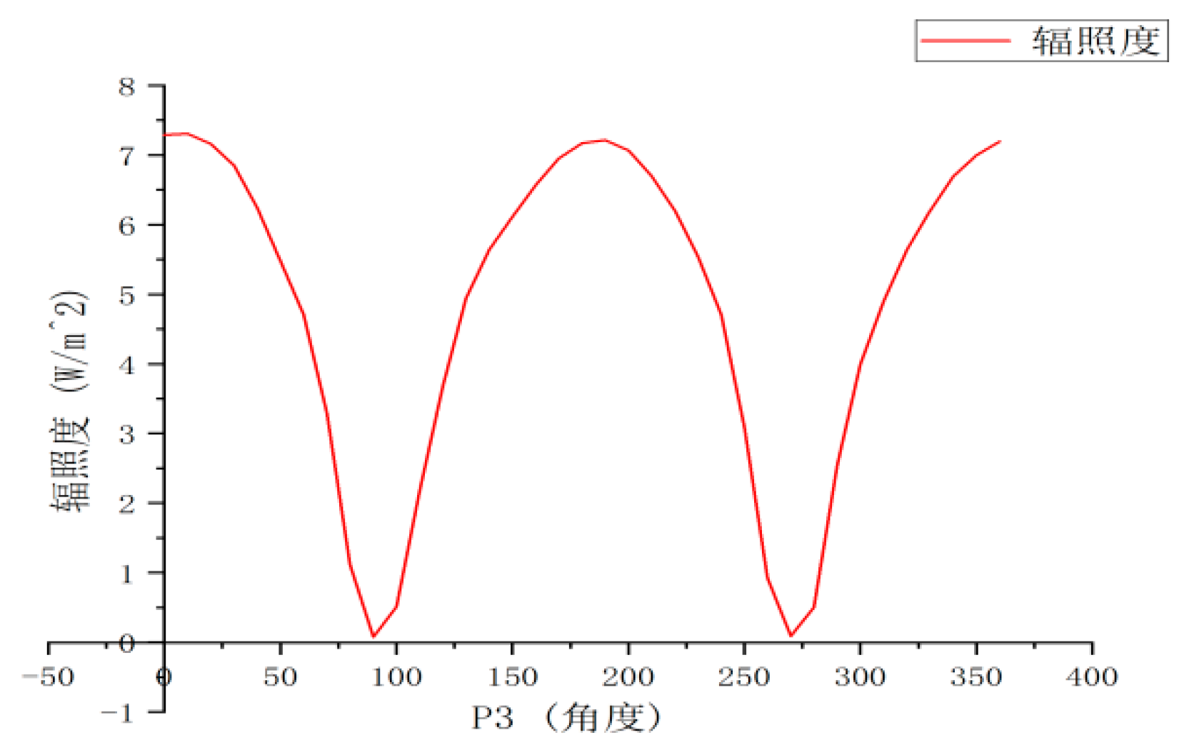
The light intensity after passing through PC: When the included angle between LC and LB changes, the light intensity does not exhibit the "abrupt drop at 45°" in Model I or the "platform within the range of 0° to 45°" in Model II (Figure 4). Instead, it follows the cosine attenuation according to Malus's law, directly negating the two sets of assumptions.
5. Conclusion
Through theoretical modeling and experimental verification, this paper reveals the limitations of the two sets of assumptions about the light transmission mechanism of polarizers: Although the models conform to Malus's law in two-stage polarization detection, the three-stage detection reveals an essential divergence from the existing theory. The experimental results show that natural light indeed becomes linearly polarized light after passing through a polarizer, and the uniqueness of the determination of the degree of polarization in the existing theory holds, leaving no room for the "disguise" of partially polarized light.
Although this exploration ended in the failure of the assumptions, it has provided a more stringent experimental verification for the theory of light polarization — when a third-stage polarizer is added, any assumption of non-linearly polarized light will lead to the deviation of the law of light intensity change from Malus's law. This process confirms the value of "falsification" in scientific research: even seemingly reasonable new assumptions need to be tested through rigorous multi-level experiments.
References
- Song Guicai, Quan Wei. Theory and Application of Physical Optics, 3rd ed.; Peking University Press: Beijing, China, 2019; pp. 247–253. [Google Scholar]
- Liu Fang, Wu Yabin, Zhao Yan. The Application of Malus's Law to Natural Light [J]. Xueyuan, 2012(3): 63.
- Xu Ping, An Wei, et al. Physical Experiments (Optics) [M]. Beijing: Beihang University Press, 2022: 97-103.
- Wu Xianqiu, Huang Zuo, et al. Modern Physics Experiment Tutorial (3rd Edition) [M]. Beijing: Science Press, 2023.
Figure 1.
Schematic diagram of polarization problem analysis of natural light.
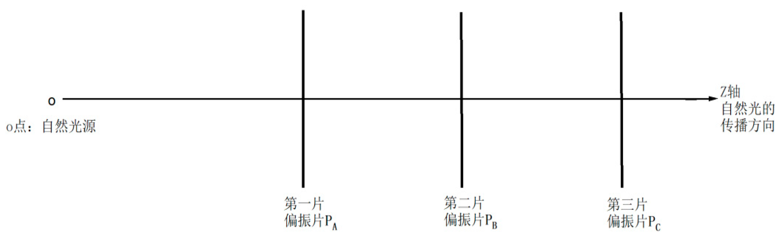
Figure 2.
Measured data diagram of the change in the irradiance of the light after the light source passes through PA.
Figure 2.
Measured data diagram of the change in the irradiance of the light after the light source passes through PA.
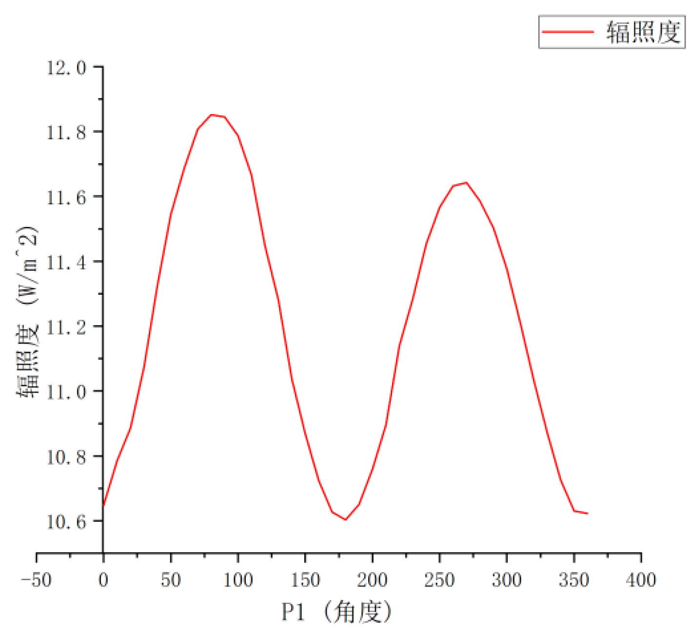
Figure 3.
Measured data diagram of the change in the irradiance of the light after the light source passes through PB.
Figure 3.
Measured data diagram of the change in the irradiance of the light after the light source passes through PB.
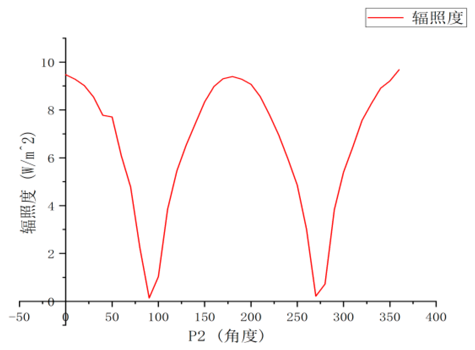
Figure 4.
Measured data diagram of the change in the irradiance of the light after the light source passes through PC.
Figure 4.
Measured data diagram of the change in the irradiance of the light after the light source passes through PC.
Disclaimer/Publisher’s Note: The statements, opinions and data contained in all publications are solely those of the individual author(s) and contributor(s) and not of MDPI and/or the editor(s). MDPI and/or the editor(s) disclaim responsibility for any injury to people or property resulting from any ideas, methods, instructions or products referred to in the content. |
© 2025 by the authors. Licensee MDPI, Basel, Switzerland. This article is an open access article distributed under the terms and conditions of the Creative Commons Attribution (CC BY) license (http://creativecommons.org/licenses/by/4.0/).
Copyright: This open access article is published under a Creative Commons CC BY 4.0 license, which permit the free download, distribution, and reuse, provided that the author and preprint are cited in any reuse.


