
Submitted:
11 April 2025
Posted:
14 April 2025
You are already at the latest version
Abstract
Magnetic levitation (maglev) technology offers significant advantages for rail transport, including frictionless propulsion, reduced noise, and lower maintenance costs. However, its widespread adoption has been limited due to the need for dedicated infrastructure incompatible with conventional rail networks. The MaDe4Rail project, funded by Europe’s Rail Joint Undertaking, explores Maglev-Derived Systems (MDS) as means to integrate maglev-inspired solutions into existing railway corridors with minimal modifications. This paper is focused in the so-called “hybrid MDS” configuration that refers to levitating systems compatible with the existing railway infrastructure. The evaluated scenario could benefit from the introduction of hybrid MDS based on magnetic levitation, where a group of pods is used in a virtual coupling configuration. In this way, this case study aims to achieve an increase in the capacity of the traffic line by significantly reducing the travel time while maintaining a similar energy consumption to that of the current conventional trains operating on this line. Simulation results indicate that hybrid MDS can optimize railway operations by leveraging virtual coupling to enhance traffic flow and reduce aerodynamic drag. The system achieves a balance between increased speed and energy efficiency, making it a viable alternative for future rail transport. An initial cost-benefit analysis suggests that hybrid MDS could deliver substantial economic advantages, positioning it as a promising solution for enhancing European railway networks with minimal infrastructure investment.
Keywords:
maglev
; maglev-derived systems
; hybrid maglev-derived systems
; linear motor
; ferromagnetic levitation
; virtual coupling
1. Introduction
Magnetic levitation offers unique opportunities for guided transport systems. Developed in the 20th century, maglev technology allows vehicles to be lifted and propelled without direct contact, using magnetic forces and electromagnetic linear motors along dedicated tracks. This technology offers several advantages over conventional rail and represents a significant step forward in transport. A key advantage is the ability to reach much higher speeds due to the elimination of rolling resistance and catenary, making maglev an attractive alternative to air travel for fast connections between cities [1]. In addition, the travel experience is smoother and quieter due to reduced vibration and noise. Another advantage is the lack of mechanical friction reduces wear and tear on components in comparison to conventional trains. Finally, maglev systems are energy efficient, contributing to lower operating costs and a reduced environmental footprint [2].
Maglev technology has been successfully tested and implemented in various locations worldwide since the 1980s, with commercial operations dating back to the 1980s [3]. These applications range from high-speed intercity connections [4] to urban transport solutions. However, despite its advantages, maglev has not been widely adopted on a global scale. One of the primary challenges is the need for dedicated infrastructure, which is generally incompatible with existing railway networks. This poses a significant barrier, particularly in regions like Europe, where well-established urban environments and extensive rail infrastructure make large-scale construction projects complex and costly. Additionally, land availability is limited, and infrastructure planning is complicated by the involvement of multiple stakeholders across different sectors. These factors make the introduction of disruptive transport solutions particularly challenging within the European Union [5].
In response to these challenges, the MaDe4Rail project [6] was launched under the Europe's Rail Joint Undertaking initiative [7]. The objective of the project is to explore innovative transport solutions inspired in maglev technology, known as Maglev-Derived Systems (MDS), and to evaluate their feasibility in Europe from a technical and economic standpoint. MDS refers to transport systems that utilise core maglev principles, such as linear motors and magnetic levitation, which may function as standalone systems or, ideally, be integrated within existing railway networks. This aspect of interoperability is central to the MaDe4Rail project, as one of its main objectives is to assess whether MDS could operate alongside conventional rail systems in Europe.
One of the main advantages of MDS is the potential to utilise existing railway corridors by upgrading them with maglev-inspired technology. The project aims to develop technical solutions that would enable integration with current infrastructure while requiring minimal modifications and civil engineering work. Ideally, this would allow hybrid operations where MDS and traditional rail services could coexist on the same routes.
As part of its research, MaDe4Rail conducted a Technology Readiness Assessment (TRA) to evaluate the maturity of MDS-related technologies. Following this, a Multi-Criteria Analysis (MCA) was performed to identify the most suitable MDS configurations for potential deployment on existing railway lines. Two key configurations were proposed: the "upgraded rail vehicle" and the "hybrid MDS".
The "upgraded rail vehicle" concept involves a track-vehicle system that minimises infrastructure modifications, allowing for local retrofitting of tracks and adaptation of existing trains by incorporating linear motor components. This approach enhances propulsion and braking performance, particularly on steep gradients and low-adhesion conditions, and enables electrification in specific areas such as marshalling yards. Results of this type of MDS vehicle have recently been presented in the publication [8].
The "hybrid MDS" configuration, on the other hand, consists of levitating transport systems designed to be compatible with existing railway infrastructure. This configuration uses Linear Synchronous Motors (LSM) for propulsion and braking installed in the middle of the track, and U-shaped sliders providing levitation directly on the existing rails or levitation beams that run parallel to the track on both sides to provide both guidance and levitation.
This paper is focused on the "hybrid MDS" based on magnetic levitation and aims to analyse its feasibility of application in a specific use case with a high potential. The study examines how MDS could improve railway operations in passenger services using a group of pods in a virtual coupling configuration, potentially replacing traditional train sets that currently provide transport services in an existing regional railway line.
In this way, this case study aims to achieve an increase in the capacity of traffic in the existing railway line by significantly reducing the travel time while maintaining a similar energy consumption to that of the current conventional trains operating on this line. The decrease in travel time is achieved through increased speeds, enabled by additional cant in curves, which is made possible by the tilting capability of the new vehicle using magnetic levitation technology. Maintaining energy efficiency despite higher speeds is accomplished by optimizing the aerodynamic drag of the capsules. This optimization is further enhanced through virtual coupling, which allows the pods to travel in closer proximity. The resulting slipstream effect and improved airflow between the pods contribute to a reduction in aerodynamic resistance, ultimately leading to lower energy consumption.
Simulation results indicate that hybrid MDS can optimize railway operations by leveraging virtual coupling to enhance traffic flow and reduce aerodynamic drag. The system achieves a balance between increased speed and energy efficiency, making it a viable alternative for future rail transport.
The structure of the paper is as follows. Chapter 2 presents a review of current propulsion technologies and the application of linear induction motors in railway systems. Chapter 3 explores key aspects of MDS implementation, including interoperability considerations. Chapter 4 describes the operational scenario under evaluation. Chapter 5 outlines the simulations performed to assess technical feasibility, while Chapter 6 focuses on the economic assessment. Finally, Chapter 7 presents the conclusions drawn from the study.
2. State of the Art
The MaDe4Rail project aims to demonstrate the potential and viability of the hybrid MDS concept based on magnetic levitation, which is a completely new concept under development.
The hybrid concept in this context is used for vehicles that can run on traditional rail infrastructure under certain conditions, normally at low speed or when stopping at stations, and in certain circumstances levitating, normally at higher speed, when conventional rolling resistance affects them more.
Levitation will be used for both suspension and vehicle guidance, while traction is envisaged with linear motors.
However, although this technology as a whole is novel and there are no direct references with which it can be compared, there are references to the basic technologies in which suspension and guidance and propulsion are referred to. Next, the state of the art of each of these will be analysed.
2.1. Suspension and Guidance
Suspension and guidance are very closely related. Electromagnetic Systems (EMS) and Electrodynamic Systems (EDS) are the most used technologies.
EMS use magnetically attractive forces between the guideway and the on-board electromagnets installed below the guideway, for accomplishing levitation. This design produces levitation even at zero speed. EMS use standard electromagnets, which conduct in the presence of electric power supply only. This results in magnetic fields of comparatively lower intensity inside the passenger compartment, making the travel more comfortable for the passengers. There are several systems developed with this technology. As an example, we can mention the following ones:
The Transrapid [9] development began in 1969, with the construction of a test facility in Emsland, Germany, completed in 1987. The last Transrapid maglev train was completed in 2005. Today, the Transrapid technology is active only on Shanghai Maglev.
The development of low-speed maglev systems in Korea began in the mid-1980s, leading to the creation of the first prototype train in 1992. In 1993, a 1 km-long maglev track was constructed for a public demonstration during Expo 93 in Daejeon [10]. This track is currently operational, serving as transportation between Expo Park and the National Science Museum.
The development of Chinese urban maglev systems commenced in 1989, culminating in the completion of the first prototype in Chengdu by 1994. The first commercial urban maglev line became operational in Changsha in 2016 [11], boasting an 18.5 km system length. A second urban maglev system in China, integrated into the Beijing Metro network, opened in 2017.
In conclusion, the EMS has been widely used in technical applications, such as German Transrapid magnetic levitation train operating in Shanghai, and some low-speed magnetic levitation systems in the world. For low-speed systems, it is not necessary to have a special guidance system on board or in the infrastructure, but for high-speed maglev systems another electromagnetic suspension must be used in the lateral direction. The EMS needs proprietary infrastructure and is so far not compatible to existing railway infrastructure. On the other hand, EDS employ magnetic repulsive force for accomplishing levitation. On-board magnets, when moving forward with the vehicle over the guideway consisting of inductive coils or conducting sheets, generate repulsive force due to interactions of onboard magnets with the currents induced in the guideway coils. This repulsive force provides the required levitation to the vehicle.
The main reference of EDS is the Chuo Shinkansen [12]. Japan started its research and development on the maglev system in 1964. The project was named MLX and the first prototype vehicle, ML100, was built in 1972. After this, a series of maglev trains have been built and tested. On April 22, 2015, the Japanese superconducting maglev system L0 achieved a running speed of 603 km/h, a record for any guided vehicle.
For the EDS, although the suspension is simple, it does not work well at low speeds, so wheels or a special gear are needed either directly under the body or on both sides of the car. It also requires specific infrastructure adaptions to be integrated into an existing railway infrastructure.
In conclusion, when comparing the two systems, EDS seems to be more flexible and useful for railway compatible systems, although, as of today, EDS systems remain energy intense for operative use and have material compatibility challenges for infrastructure integration due to the use of conductive material such as aluminium. But the main inconvenience of these two technologies is that they require a specific infrastructure where the track is a T-shaped beam that supports the vertical suspension and lateral guidance system, being incompatible with traditional railway.
On the other hand, the technologies with the greatest potential for use in hybrid MDS are passive levitation.
The first one is the electrodynamic systems based on permanent magnets, which consist of a modified form of the conventional EDS system. It is a passive levitation system [13] based on the principle of magnetic repulsion. It uses permanent magnets at room temperature, arranged in the form of a Halbach array. Unlike a conventional EDS system, this system does not require any super-cooled magnets, neutralizing any cryogenic requirements. However, the system requires auxiliary wheels to accelerate the vehicle until it acquires some initial take-off speed, after which it starts levitating.
The second one is the ferromagnetic passive levitation system [14], a technology based on the coupling of a U-shaped magnetic slider which integrates passive permanent magnets with a ferromagnetic rail (Figure 1). The magnets are configured on the movable elements to provide vertical support. It is based on permanent magnets at room temperature and provides the levitation force both in static conditions as well as in dynamic conditions. The system can also be integrated with the guidance system.
Ferromagnetic passive levitation technology can operate on a standard rail form with auxiliary integration systems for low to medium speed applications, or it requires a specific integration infrastructure for high-speed applications. Its benefit as a suspension system is the possibility to have high levitation efficiency if compared to the other available technologies and the use of low-cost steel guideways.
2.2. Propulsion
Linear motors are the key technology most commonly used for propulsion.
On the one hand, Linear Induction Motor (LIM) is an asynchronous electric machine that usually is made of two parts – active part that is a winding (usually 3-phase) that generates the electromagnetic field and the reaction plate where the eddy currents are generated. The active part in most cases is mounted on the vehicle.
On the other hand, Linear Synchronous Motor (LSM) possesses high force density along with high efficiency and high-power factor as compared to linear induction motors. Since it is a doubly excited motor, it incorporates a DC excitation source in its structure. To make the system contactless, generally permanent magnets are used for DC excitation and fitted in the translator. The translator forms the onboard part and moves with the vehicle. The distributed stator windings are laid on the tracks and energized with the help of ground converters which gives it a long stator configuration. Excitation of stator windings generates moving flux that moves at synchronous speed. DC magnets fitted on translator generate constant flux. When both of these fluxes interact, a magnetic locking is produced that impels the translator to move at synchronous speed.
The application of linear motors to railways was first proposed over a century ago, initially for conventional vehicles with steel wheels on steel rails. This system involved motors mounted on the vehicle, along with additional structures attached to the track to support the motor functions. A detailed historical progression of this technology and its systems is provided in reference [15].
Some of the earliest practical applications of linear motors in railways include the Linear Induction Motor Research Vehicle (LIMRV) [16], and the air-supported RTV31 [17] and the Aerotrain S44 [18].
The advancement of liner motors technology accelerated with the introduction of pure maglev systems. Extensive research and development efforts in Germany led to the Transrapid system, which became commercially operational in Shanghai in 2004. Transrapid vehicles incorporate electromagnetic suspension (EMS) and utilize a long primary linear synchronous motor (LSM) for both traction and braking [9].
In Japan, the HSST Linimo urban maglev uses EMS and a short primary LIM [19]. Japan has also made substantial progress in developing a high-speed maglev system utilizing electrodynamic suspension (EDS) with superconducting magnets and a long primary LIM for traction and braking [20]. Similarly, the Incheon Airport line in South Korea [10] used a short primary LIM.
At present, linear motors is a well-known technology, and several projects have demonstrated that the technology is fully operational on separate tracks. However, conventional rail-compatible systems are still under development. The LIM is generally not preferred over the LSM for speeds above 300 km/h due to its lower efficiency, higher eddy current losses, lower power density and lower power factor.
Linear motors are used as a service brake and for emergency braking, but also in combination with mechanical braking for redundancy.
From the state-of-the-art analysis, it is clear, after examining the current state of the art, that existing systems are not designed to operate on a shared infrastructure and therefore lack interoperability.
However, it is possible to use technology that allows the development of the idea of the project as a whole.
3. Hybrid MDS Technological Basis
This section contains the main aspects to be considered for hybrid MDS implementation including a description of the proposed technology for both the vehicle and infrastructure, including the main implications of the linear motor implementation and all the aspects of interoperability that are mainly related to the compatibility of the hybrid MDS with existing track infrastructure and the signalling system.
For the technological basis of the following assessments, the vehicle propulsion system will be linear synchronous motors, while the levitation and guidance will either be based on U-shaped sliders on existing rails or on additional levitation beams that are installed parallel to the conventional rails. The proposed solution is based on the NEVOMO MagRail concept [21] and the IRONLEV technology [22].
3.1. Propulsion, Levitation and Guidance Systems
The requirement of an interoperable infrastructure is of the utmost importance for the hybrid MDS concept. While conventional full maglev systems require purpose-built infrastructure, hybrid MDS solutions offer the flexibility for mixed operations of conventional railway rolling stock alongside MDS vehicles without a new and dedicated linear infrastructure.
The system introduced in this paper entails the implementation of a hybrid MDS based on Maglev technology on existing railway lines. In this scenario, MDS vehicles will utilise the existing infrastructure and coexist with conventional trains on the same lines. Magnetic systems will be responsible for propulsion, guidance, and levitation.
The fundamental unit of Maglev rolling stock will be a single vehicle, also called pod, similar in size to a standard coach, with a passenger capacity of approximately 70 seats. These pods can be combined into "platoons", comprising two or more virtually coupled vehicles, without mechanical connections.
While the MDS pods can operate on wheels like conventional trains, using bogies similar to those found on traditional rail vehicles when operating without levitation, they begin to levitate slightly above the rails when operating in a corridor designed for levitation. The suspension and guidance systems of MDS pods require the implementation of a levitation system based on permanent magnet arrangements of on-board sliders, as shown in Figure 2. These sliders, connected to the vehicle structure, ensure that the pods follow the track profile and provide the necessary levitation and guidance forces.
In order to ensure lateral confinement and centring, lateral stabilisation systems are essential, in addition to magnetic levitation systems. These systems are only operational when the pod is in levitation mode, and are integrated on the levitation sliders, interacting with the ferromagnetic rails to ensure centring and stabilisation.
Adapting the infrastructure appropriately to meet the specific needs is crucial to harnessing the positive effects of the new system. Consequently, the infrastructure comprises a conventional (existing) railway line supplemented with additional components to provide propulsion and levitation. In this way, infrastructure equipped with such MDS components will be always interoperable with conventional vehicles, as shown in Figure 2, and will not create obstructions in conventional railway operations.
The new system needs additional components to provide the needed energy for the linear motor. Deployment of the power electronics subsystems contains especially grid and motor power converters, section switches, cables for power and communications and the centre for motor control. The levitation system will use passive levitation and needs no additional energy provided by the infrastructure.
Two configurations have been considered. The configuration A, also called “series configuration” involves the analysis that will evaluate the implementation of the existing line with minimum MDS technology, reducing investment costs for the modernisation of the infrastructure.
This intervention will lead to evaluating the applicability of the new technology on the basis of the minimum achievable requirements: LSM for propulsion; U-shaped sliders on existing rails for levitation, and the existing line alignment (Figure 3). In the cross-section, conventional elements such as the sleeper (1), the rails (2), and the linear motor (3) appear, including the levitation system (2), represented in green in direct contact with the rail. The configuration must be designed in such a manner that the UIC structure gauge is respected (green dashed line is the structure gauge). In this configuration, the levitation and guidance system are based on the principle of magnetic induction between materials with different permeabilities (ferromagnetic levitation), through the interaction of a U-shaped slider with a ferromagnetic rail. The existing standard rail will be used and no additional equipment will be needed from trackside. The movable part is made of appropriately arranged permanent magnets in a U-shaped ferromagnetic profile. The rail is made of a material with high magnetic permeability, such as iron. The interaction between the slider and the rail generates a vertical force that suspends the load.
To enhance passenger comfort at higher speeds, the pods will feature a tilting angle of 6° through a mechanism using magnetic forces that compensates for the track’s cant in curves. The “series” configuration will allow the MDS to integrate seamlessly with the existing infrastructure.
On the other hand, the configuration B, also called “parallel configuration” involves the analysis that will evaluate the implementation of the existing line with magnetic levitation technology, with all the technological and/or infrastructural upgrade interventions necessary for the system to function optimally and with the maximum attainable performance.
Figure 4 shows a cross-section where the main components can be seen. In this cross-section, next to the conventional elements, like sleeper (1) and rails (2), the linear motor (3) between the rails and additional levitation beams (4) outside the rails.
This configuration introduces levitation beams that run parallel to the track on both sides, and that will provide both guidance and levitations to newly designed pods with sliders that will adapt to the levitation beams. It would allow different configurations of cant: standard rails will maintain the existing integrated cant for traditional trains, while parallel levitation beams will allow MDS capsules to travel at higher speeds on bends thanks to an additional integrated cant.
For this configuration, a key element in the operation of MDS vehicles on existing infrastructure in the event of a potential infrastructure enhancement is the necessity for supplementary cant to attain elevated velocities, whilst concurrently ensuring interoperability with conventional trains on the same tracks. The TSI 1299/2014 [23] specifies the permissible cant, which is limited to a maximum of 160 mm (or 180 mm for tracks exclusively utilised by passenger services). In cases where greater cant is required to attain elevated velocities, the installation of MDS components can be implemented in a manner that exclusively affects vehicles operating in high-speed levitation mode, as illustrated in the subsequent stage of Figure 5, allowing that the built-in cant remains consistent for all vehicles operating on wheels and standard rails, but vehicles in levitation mode can benefit from a higher cant, built in under the additional levitation beams outside the standard rails.
In both configurations, the propulsion system is based on a linear synchronous motor (LSM), where the vehicle's propulsion system (mover) is energetically passive, consisting of NdFeB (Neodymium Iron Boron) permanent magnets arranged on a steel core, whilst stator is installed in between the existing rails fixed to the sleepers or slab track. The vehicle movement is controlled from the linear motor side. An electric power command and control system, based on sections and segments of the linear motor stator, enables precise vehicle position control on the track with an accuracy of up to 5 cm.
Inverter stations are used to deliver needed power to the linear motor. A schematic drawing in Figure 6 depicts the architecture of the power supply chain from the MV grid to the stator.
To improve the efficiency of the drive system, the stator is divided into shorter segments called sections. This division allows for the use of smaller converters that supply energy only to specific sections, i.e., the sections where the vehicle is present. A separate substation with a power electronic converter supplies each section. This division is shown in Figure 7.
In each section, one vehicle can be moved individually. Section lengths define the minimum distance between vehicles; for example, in stations or areas with a lower speed and higher density, the sections are shorter than on open network lines with bigger distances between vehicles. Each section requires its own inverter station, so the length of the section is determined based on specific operational–economic analysis for each use case.
Thus, the propulsion system consists of a stator installed between the existing rails attached to the sleepers or slab track, a mover equipped with permanent magnets attached to the vehicles, a control centre to command the linear motor, and reversing stations in the infrastructure to supply the necessary power to the linear motor.
3.2. Interoperability Needs and Compatibility of the MDS with the Existing Signalling System
The primary interferences identified in the project between the MDS technology and the existing signalling system are the compatibility between signalling components on the track and MDS components, such as the linear motor, and the electromagnetic interferences (EM) generated by the linear motor on signalling components. This issue is the same as that analysed for the case of the upgraded MDS presented in [24].
On the other hand, in Europe, most modern lines are equipped with the ETCS Level 2 system, which represents state-of-the-art railway signalling technology. The signalling system is based on several consolidated concepts, including the utilisation of a train detection system (TDS) for the identification of trains along the line, the deployment of Eurobalise for the verification of train positioning along the designated route, and the integration of radio communications. The use of TDS on the line depends on the type of signalling applied. If the signalling also uses TDS for the location of the train along the line, then it is essential to verify its compatibility with the MDS vehicles.
The integration of MDS vehicles within the existing infrastructure may potentially impact the operation of the signalling system and must be compatible with it. For the specific hybrid MDS Configuration A, the use of magnetic sliders for the levitation on the existing rails interferes with the axle counters. In this case, the problem can be solved using track circuits instead of axle counters.
Other possibility can be the adoption of TDS that implement the safe localization of the train using other sensors, like for example on-board sensors that detects digitally encoded location flags on the guideway.
Existing balises will be used for conventional vehicles while virtual balises will be used for MDS vehicles. This type of approach, however, requires that there is a signalling system that safely identifies the presence of the train without the use of traditional TDS. In this case, possible alternatives include new field devices that are using new sensors connected to the Interlocking for train detection in the ETCS Level 2 scenario or adopting ETCS moving blocks without TDS.
Finally, a second source of EM interference is given by the levitation system. In this study, a passive magnetic levitation system has been evaluated. Based on the magnetic simulations performed, no influence is expected from the EM field generated by the sliders on the balises which are in the middle of the track, however the influence of the field on the track circuit should be studied more in detail in further research.
4. Operational Scenario to Be Evaluated and Context Analysis
As previously mentioned, hybrid MDS comprise levitating transport systems designed to be compatible with existing railway infrastructure. The considered case study aims to evaluate the possibility to retrofit existing regional lines as an alternative to building new HSR lines.
The use case is proposed on a typical regional line with passenger traffic services where the implementation of a hybrid MDS in an existing line is proposed as an alternative to the construction of a new HSR (High-Speed Railway) line.
For the close to 550 km line considered in the case study, conventional intercity services take almost 6 hours. The objective is to carry out a comparative analysis of the capacity of the line comparing journey times and energy consumption between a conventional intercity regional train (referred to simply as IRT in the remainder of the paper) travelling on that line and a convoy of pods based on MDS technology with the same passenger capacity.
The considered operational scenario provides an overview of how a Maglev line operates, using pods connected by means of virtual coupling forming a platoon as rolling stock and employing a mixed operation of traditional train and maglev technology with MDS pods movements governed by GOA4 (Grade of Automation 4) at maximum speed of 220 km/h with an acceleration of at least 1.5 m/s², and an operational deceleration of 1.5 m/s. A single pod can have up to more than 70 passenger seats.
Two scenarios have been considered, one for configuration A and the other for configuration B mentioned above.
5. Performance Analysis of the Proposed Solution
The objective of this section is to evaluate and demonstrate the benefits of the proposed technology under a theoretical pilot line designed for intercity regional services.
This use case compares a conventional intercity regional train (IRT) with four coaches to a set of four pods operating in a Hybrid MDS configuration with virtual coupling. Both run on the same railway line, but the pods benefit from increased speeds in curves due to additional cant, enabled by vehicle tilting. This feature enhances passenger comfort while reducing cant deficiency, allowing for higher speeds.
The analysis focuses on comparing travel time and energy consumption between a conventional train and an equivalent pod configuration in terms of transport capacity, leveraging the advantages of MDS technology. The four pods are considered virtually coupled when they arrive at stations simultaneously without delays. The choice of four pods aligns with station platform constraints, ensuring they occupy the same space as the IRT.
This use case could benefit from hybrid MDS with magnetic levitation, using a virtually coupled pod system. The objective is to significantly reduce travel time while maintaining energy consumption similar to conventional trains.
The reduction in travel time is achieved by the increase in speed in curves, facilitated by additional cant developed through vehicle tilting. Depending on the configuration, this cant can be introduced either physically, by adding built-in cant under the levitation beams, or directly through magnetic levitation. Energy efficiency is maintained despite increased speed by minimising aerodynamic drag. Virtual coupling allows pods to travel closer together, leveraging slipstream effects to reduce aerodynamic resistance and energy consumption.
To estimate potential speed increases in curves, the pilot line was analysed using a stepwise approach. Initially, speeds were calculated based on existing cant and allowed cant deficiency to establish current performance limits. Then, potential speed increases were evaluated for two configurations.
For the configuration A, the levitation system utilizes existing rails, maintaining built-in cant while introducing vehicle tilting (maximum 6°) to enhance passenger comfort. This approach minimizes investment costs but limits speed increases to passenger acceptance levels of tilting technology.
For configuration B, additional levitation beams enable independent cant optimization for levitating and conventional rolling stock. This requires higher investment but allows for greater built-in cant for levitating trains without affecting conventional rail operations.
Velocity calculations for Configuration B followed two steps. First, speeds were restricted by regulations on built-in cant, cant deficiency, and transition curve constraints. Then, based on other transport systems, new values were proposed to highlight the system’s potential. Maximum speeds were determined for each curve by applying the highest permissible cant deficiency to the given infrastructure.
For Configuration A, speed increases rely on tilting mechanisms, similar to existing tilting trains like Pendolino (Italy), X2000 (Sweden), and ICE-T (Germany). Excessive tilting can cause passenger discomfort, so tilting angles must be carefully managed.
For Configuration B, the use of levitation beams allows for optimized cant values. The maximum MDS cant is achieved by combining built-in cant from the levitation beams with a slight vehicle tilt of 1°, balancing speed enhancements with passenger comfort.
This approach ensures a thorough evaluation of the potential benefits of MDS technology in improving intercity rail services.
5.1. Virtual Coupling
In recent years, the railway sector has focused its efforts on increasing the capacity and flexibility of lines by improving the current railway operation. Research has focused on increasing capacity by reducing the headway or the distance between trains. Moreover, railway traffic control and signalling systems based on moving-block systems (MBSs) have been developed, such as the Communication-Based Train Control (CBTC) system [25] which is mainly used in urban and Automated People Mover (APM) railway lines, and the European Rail Traffic Management System (ERTMS L3, recently denominated ERMTS Level 2 with moving block) [26] for main and commuter lines.
Additionally, the coupling of train units to form convoys has been proposed, for enhancing the average passenger train speed, energy efficiency, and capacity utilization of railway infrastructure, among other aspects. One approach is based on the use of Virtual Coupling (VC) to virtually change the compositions of the consists at the cruising speed via communication [27]. Clearly, more trains can run on the line if the spacing between trains is reduced. Thus, the line capacity is increased. In [28], a multi-state train-following model was developed for describing VC procedures conduct a comparative capacity analysis with other signalling systems. The results indicated that VC has a superior capacity to MBSs, and it was estimated that VC could reduce the distance between trains by 64% for European Train Control System (ETCS) Level 2 and by 43% for ETCS Level 2 with moving block.
Consequently, in addition to increasing the capacity of the line, VC can provide a more flexible mode of operation, with trains behaving as if they are physically coupled. This makes it possible to run trains in smaller sets but adapt to the circumstances [29].
VC is based on the principle of the Relative Distance Braking Mode (RDBM). RDBM concepts have been widely applied in control systems for road traffic, autonomous vehicles, and platoon cars. The RDBM system is similar to the on-road mode of operation, where vehicles drive at a safe distance from the vehicle in front and the driver reacts to the brake lights of the vehicle in front, which is far shorter than the required braking distance for a full stop. This idea is fundamental to vehicle platooning and autonomous vehicles.
In the RDBM, it is assumed that two consecutive vehicles are in motion, and depending on their braking speeds, the safety margin between them can be reduced. Thus, if the first train (leader) is running at speed and braking with deceleration and the second consist is running at speed and braking with deceleration , the position of the follower can be calculated as:
Figure 9 shows a schematic of the relative-braking concept.
5.2. Simulation Model
The model defining the train motion of this work is based on the principles of longitudinal train dynamics (LTD). Hence, the train is considered a point mass with one degree of freedom, where the traction/brake system, rolling resistances, air intake, aerodynamic drag, and slope and curve resistances are applied. This simulation model has been included and explained in detail in references [29,31] and corresponds to the following equations:
where s (m) and v (m/s) denote the position and train speed, u (N) is the controlled driving/braking force, F (N) is the integrated driving/braking force, is the resistance force due to the track, τ is the inertial lag of the longitudinal dynamics, M (kg) is the train’s mass, A (N) is a term that includes the rolling resistance plus the bearing resistance, B (Ns/m) is a coefficient related to the air intake, C (Ns2/m2) is the aerodynamic coefficient which coefficient depends on the driving speed and the distance between pods as explained in the next section, and (m/s2) represents the uncertainty contemplated in the robust control in terms of acceleration as for example in the estimation of the aerodynamic drag.
5.3. Aerodynamic Drag in Virtual Coupling Configurations
As shown in the next figures, due to the proximity of trains in virtual coupling, the airflow between trains can significantly affect factors such as air resistance during train operations, thus affecting the train dynamics. Therefore, building an accurate model for train drag in virtual coupled convoys plays a crucial role in achieving smooth tracking control of the trains in the virtual coupling. The effects of virtual coupling are very relevant as there is a reduction of drag which results in lower energy consumption.
Since the goal is to obtain the drag coefficient for different speeds and distances and to conduct an extensive parameter sweep, 2D simulations have been chosen, significantly reducing computational time. Although some 3D effects are lost, it has been verified that the drag measurements agree with values obtained for real trains and 3D simulations.
The computational domain has been defined to leave a space of between inlet and train and between last train and output. In the vertical direction, a space of has been left. The mesh is an adaptive mesh with finer resolution near the train walls, with a size of , and a coarser resolution far from the trains, with a size of , while between trains the same linear interpolation as from the last train to the output is used.
The presented simulations have been carried out in OpenFOAM [31] using a steady finite volume method for compressible flow. Turbulence has been modelled using the SST model with a boundary layer model when necessary. In all simulations, remains below the critical values for the turbulence model with the given mesh.
Figure 10 and Figure 11 show the results of the CFD calculations for a single pod configuration, where a Cx of 0.31 has been obtained. This is the coefficient of an individual pod and is the one to which the trains of a convoy tend asymptotically when the separation between units is sufficiently high.
On the other hand, Figure 12 shows results for a 4-pod configuration, which is the one used in this use case to compare it with the IRT.
Calculations for both relative braking (virtual coupling) and absolute braking (ERTMS L3) have been included. These figures show that when, for the same speed of circulation, the separation between pods is greater, the slipstream effect is less, which translates into a lower reduction in resistance and, therefore, higher energy consumption than when the pods are closer together, as is the case with VC.
Different CFD simulations have been carried out for different speeds of circulation and for different separations between pods, with the result that the Cx coefficient depends on the driving speed and the distance between pods, so that, as a final result, a 3D function has been obtained for each pod to obtain its value.
Figure 13 shows the Cx functions obtained for each of the 4 pods, representing the variation of Cx as a function of the distance between pods and of the driving speed.
These Cx results have been used to establish the coefficient C in equation (2) as a function of the pod's speed and the distance between pods, and these are the results that will be used in the simulations carried out in the following subchapter.
5.4. MPC Controller Design
Considering a convoy composed of a leader and n followers (3 in our case), all of them have length L. The superscript indicates the pod, with 0 for the leader and i, where i= 1,…,n, for the followers.
A decentralized VCTS control problem is considered with independent controllers for the leader and each follower.
With the proposed control strategy, the leader will track a given speed curve, and the followers will guarantee a safe minimum distance between pods and the string stability of the VC. For the followers, we design an MPC robust controller that ensures a safety and control efficiency while considering the parameter uncertainties.
When using a decentralized control architecture, the leader can operate under any control and signalling method. Therefore, the leader can use any conventional control method based on Automatic Train Control (ATC) or ETCS.
For simplicity, for the leading train, we use a driving mechanism based on an ATC system that tracks a given speed curve. This speed curve is obtained using a Dynamic Programming (DP) approach. Because the role of the leader is to set the convoy’ movement policy, we use the DP approach to precompute the reference behaviour of the leader. Then, the result of the DP establishes the general policy followed by the train’s convoy. In this paper, we use a policy with an optimal speed profile that finds the maximum velocity permitted by the speed limitations imposed by the line operation, thereby satisfying the speed constraints at all times. A detailed explanation of the implementation of this DP approach can be found in [32].
For the controller design for the followers, a model predictive control (MPC) approach is used. The MPC optimizes over a finite time horizon but implements only the current time window of the finite horizon optimization problem solution.
The complete formulation of the optimisation problem used to construct the MPC controllers of the leader and the followers can be found in reference [29].
In general terms, as specified in (5), the MPC optimisation problem minimizes a cost function during the prediction horizon subject to three types of constraints: the states should follow the dynamic equations (2)-(4), as specified by (6); the speeds should respect the speed limits, as specified by (7); and the force , which is the solution of the optimization problem, must respect the maximum traction and braking capabilities of the train (8). In the follower’s case, a fourth type of constraint (9) is added, in which the follower should respect the RDBM with respect to the train that is moving in front.
subject to:
5.5. Analysed Configurations
To assess these scenarios, two possible MDS vehicle configurations have been evaluated with respect to the basic configurations of a conventional rail vehicle which is currently running on the line under study. The characteristics of this conventional rail vehicles are as follows:
Table 2 shows the main characteristics and main parameters for the IRT:
And for an individual pod, Table 3 presents the characteristics that have been considered:
Two different alternatives have been considered in terms of traction capacity of the MDS pod:
- Maximum acceleration of 0.75 m/s2. This acceleration leads to a maximum tractive effort of 35 kN. This option has been limited to 1500 kW of power. In order to be able to implement acceptable virtual coupling conditions, a maximum braking deceleration of 1.2 m/s2 was set, leading to a maximum braking effort of 52.32 kN. This maximum deceleration is also justified as a way of establishing a braking capacity similar to that originally proposed (of 1.5 m/s2) but within the usual maximum deceleration margins for conventional trains,
- Maximum acceleration of 1.5 m/s2. This acceleration leads to a maximum tractive effort of 71 kN. This option has been limited to a power of 2263 kW. The maximum braking deceleration is 1.5 m/s2, which leads to a maximum braking effort of 71 kN.
These values are summarized in Table 4.
5.6. Simulation Model
As previously mentioned, the model defining the vehicle motion of this work is based on the principles of LTD. The parameters considered for the rolling resistances are summarized in Table 5. The values for the pod have been obtained from the magnetic drag calculations carried out in the following sections:
5.7. Simulation Results
Figure 14 presents the line characteristics with two simulation scenarios. Scenario A represents Configuration A for 220 km/h and scenario B represents Configuration B with optimized infrastructure for 220 km/h.
Figure 14 presents the reference limit speeds for the 2 scenarios (A and B) and the IRT as a reference. It can be seen that the maximum speed profile of Scenario B is slightly more stable than Scenario A in some sections, maintaining the maximum speed for a longer time. Slightly higher maximum speeds are also reached at some points along the line. The IRT profile is the one with the lowest speeds.
In summary, the difference between the two scenarios is that in Scenario B the infrastructure is optimised to achieve sections of the line with higher speeds than in Scenario A. However, the maximum speed of the line is also 220 km/h.
The simulations were carried out by dividing the line into three sections. The first comprises stops 1 to 3, the second from stops 3 to 9 and the third from stop 9 to the end of the line.
The behaviour of the different vehicles on the line has been simulated using the model presented in the previous section. The following figures show the obtained results. Only the 1st pod of each convoy is plotted for each simulation and no follower pods are included for clarity.
Figure 15 shows the plot of travel time versus vehicle position on the railway line (only for the second sector, stops 3 to 9). It shows how, for the same route and with the same stops, the IRT is much slower and takes more time to complete the journey. In contrast, the different pod configurations achieve similar performance, reducing total travel time from 5.39 hours with the IRT to times ranging from 3.96 to 4.13 hours depending on the pod traction capacity configuration considered, achieving an average reduction in travel time of 25%.
Figure 16 shows the speed and longitudinal acceleration of individual vehicle at each point of the journey. On the left-hand side, it is shown as a function of journey time, and on the right-hand side, as a function of kilometre point.
The simulated section is the one between stations 3 and 9, which involves 6 stops (not counting the departure station).
Figure 16 also shows an improvement of all pod simulation scenarios with respect to the IRT and again visualises how pod configurations need considerably less time to complete the route.
Figure 17 presents the traction/braking requirements in terms of force and power for the different traction capacity configurations. Here, the same trend can be seen again.
For greater clarity, Figure 18 shows force and power plots with zoom between kilometres 265 and 315 km (i.e., the section between the stations 8 and 9). It can be seen that the IRT reaches 300 kN and 3400 kW and that the pods reach forces and powers according to the maximum allowed for each simulation case. As expected, the highest traction and braking capacities are used during changes of speed and remain relatively low during cruise speed sections.
It can also be seen that for most of the journey the vehicle is travelling at cruising speeds, and that maximum traction and power capacities are only required during acceleration and braking manoeuvres. This higher traction and power capacity of the train means that the more powerful pod configurations allow for shorter journey times, but, as they are only used in very specific areas of the route, the final travel times are very similar for all pod configurations.
Finally, and in order to have elements to evaluate the use of this technology, Figure 19 is included, where the energy consumption during the whole journey is evaluated. Two values have been calculated, one for a system without regenerative braking, and the other with regenerative braking, considering an efficiency of 85%. Figure 19 shows the energy consumed in each simulation case. The term 'total' refers to the sum of all the vehicles involved. Therefore, the IRT label represents the consumption of the intercity regional train alone, while the other labels show the combined consumption of the four pods. "Net energy” refers to the net energy consumed if a recovery efficiency of 85% is considered. In other words, during braking, energy is subtracted from the total accumulated in the graph. In the two lower plots no energy recovery is considered.
5.8. Conclusions
With regard to travel time, the results show how, for the same route and with the same stops, the IRT is much slower and takes longer to complete the journey. In contrast, the different pod configurations achieve similar performance, reducing the total journey time from 5.39 hours with the IRT to times ranging from 3.96 to 4.13 hours depending on the pod configuration considered, achieving an average journey time reduction of 25%, as seen in Table 6.
This is due to the increased running speed achieved by the extra cant implemented using magnetic levitation technologies and is one of the main contributions demonstrated by this use case.
However, when comparing the energy consumption of the different configurations, the IRT consumes less energy than the pod convoy. This result is logical since they run at lower speeds and, even if the journey takes longer, the main component conditioning energy consumption is aerodynamic drag, which depends on the square of the speed.
The results of these analyses are shown in Table 7.
The results show an increase in power consumption of the pod convoy by 10-17% compared to the IRT. Of the pods configurations, the lowest consumption is Scenario A with virtual coupling and a traction capacity of 0.75 m/s2, while the highest consumption occurs in the scenario of higher performance (Scenario B and 1.5 m/s2).
However, it is worth noting the great advantage of virtual coupling from the operational point of view. While for a conventional train, the length remains constant at all times of the operation, in a pod convoy the number of pods can be adjusted according to demand at a given time slot, so that in low-demand considerations the convoy could be formed by one or two pods, reducing then the energy consumption to a quarter or a half. In this case, the new proposal is clearly more advantageous than the traditional fixed trainset solution.
On the other hand, to see the beneficial effect of virtual coupling on consumption reduction, a simulation has also been made for Scenario B configuration with 0.75 m/s2 for absolute braking (ERTMS L3), where the pods run at a greater distance from each other.
If the results are compared with brake energy recovery, although this use case is not very relevant because not many braking situations occur, the results are more favourable for the conventional rail vehicle, probably due to its higher mass.
On the other hand, since the main factor influencing consumption is aerodynamic drag, better aerodynamic design will undoubtedly result in lower energy consumption.
In this use case, and in order to compare configurations of conventional vehicles and pods that are as similar as possible, we have chosen to use pods with the same aerodynamic characteristics and the same front end as the IRT, so that there is no doubt that the improvement in the aerodynamics of the pods will significantly reduce energy consumption.
As an estimation, Table 8 shows how by optimizing the aerodynamics of the pod, it is possible to obtain Cx reductions that imply a reduction in the consumption of the pod convoy that would allow to achieve a consumption practically equal to that of the IRT, but with an increase in average speed and the consequent decrease in travel time very significant (25%).
Finally, when comparing ERTMS L3 with virtual coupling, from the table data, it is also possible to estimate the improvement in energy consumption due to the use of virtual coupling (VC) instead of ERTMS L3, which is 9%, due to the aerodynamic optimization caused by the slipstream effect when the vehicles drive closer together.
Consequently, the results show that the considered proposals are of great interest and show potential for application.
6. Economic Cost–Benefit Analysis
This section aims to perform a cost–benefit analysis (CBA) of the selected use case in order to assess its socio-economic impact. The study focuses on evaluating the specific socio-economic impact of implementing the MDS under study. To achieve this, a comparative analysis between a reference scenario (IRT running on the existing line) and the two proposed configurations (A- series, B- parallel) was conducted considering various economic performance indicators, such as economic net present value (ENPV), benefit–cost ratio (B/C), and internal rate of return (IRR).
The CBA was conducted following the European Commission (EC) guidelines [33,34]. The abbreviation m EUR is used to refer to millions of euros [35].
More detailed information for this analysis can be found in [36].
6.1. Design Inputs for the CBA
In order to conduct a CBA and facilitate a comparison between the reference scenario and the project scenario, a number of assumptions have been made regarding different modes of transport (rail and road).
In terms of rail traffic, a total of over 150 services per day, corresponding to approximately 28000 train-km, are presumed to be replaced by MDS convoys in the project scenarios.
Overall, it is estimated that the total number of pod-km provided on an average weekday (considering both directions) will amount to approximately 275000 pod-km per day.
6.1.1. Investment Costs—CAPEX
For both scenarios, the implementation of a linear motor is required along the whole line and in the specific MDS tracks at the stations, because the new operated MDS vehicles will not have an onboard propulsion system for reaching the travel speed. The scenario A configuration (Hybrid MDS based on maglev with “series” configuration) will use the existing rails for the levitation function, therefore additional levitation beams are not needed.
The hardware costs per kilometre for the linear motor in the considered configuration for this study is estimated by Nevomo experts to a target price in line with the market of 3.25 m EUR - km for a single track, including the active stator with all fixtures and cablings, power electronics like inverters, transformers and segment switches, and the control system. For the scenario B, the cost of the levitation beams components is estimated in 2.2 m EUR - km for a single track. Additional planning and deployment costs of 0.25 m EUR - km are also part of the installation of the linear motor and 0.20 m EUR - km for the levitation beams.
Changes in vehicle command and control system, signalling system and Telecommunication system are estimated by CCS tech developers at 50000 EUR - km for an estimated the complete double-track line, the CCS costs are estimated to be of 57.2 m EUR.
On the vehicle side, both scenarios involve the use of newly designed lightweight pods capable of carrying 70 people and achieving speeds of up to 220 km/h.
For the new pod, the costs for interior, structure and general technical equipment are taken directly from a standard HSR vehicle, adjusting the value per offered seat, assuming this will be the comparable standard also for the new pod design. Since the pods will not have an engine or an onboard propulsion system, these costs were excluded. The estimated cost per pod, including vehicle structure, technical equipment and interiors is 2.51 m EUR. Since the bogies will be equipped with magnets for the propulsion and levitation systems, their cost will be significantly higher than those of standard bogies. Therefore, a different estimation was required. Based on experience with the prototype at the Nevomo test facility and the costs of regular passenger coach bogies, the estimated cost is 1.5 m EUR per a set of two bogies for one pod. As a result, the total estimated cost per pod, including structure, technical equipment, interiors, and MDS bogies, amounts to 4.51 m EUR. In summary, when all these costs are taken into account, the cost per seat is estimated to be well below that of a conventional high-speed train. In the use case, the rolling stock leads to an investment 682 m EUR for 170 pods, which would be able to replace the existing trains and provide services accommodating both existing and induced demand.
6.1.2. Operational and Maintenance Costs—OPEX
A rate of 2.5% of the infrastructure investment costs has been considered for infrastructure maintenance, resulting in additional annual costs of 91.6 m EUR /year.
Similarly, the maintenance and depreciation costs for rolling stock have been estimated to be 2.5% of the rolling stock investment costs, considering the necessity to maintain the rolling stocks in optimal conditions, resulting in a total cost of 17.05 m EUR /year.
For the maintenance, depreciation and operational costs of traditional trains used for regional services, a value of 12.44 EUR train-km was used, based on the values of operational costs for trains ranging from 161 to 480 offered seats, obtained from the service contract of Trenitalia, for the provision of regional services in the proximity of the analysed line [20]. This value was divided into 5 cost items, based in percentages (Personnel on Board: 36%, Rolling Stock Depreciation: 18%, Maintenance: 26%, Inspection and Cleaning: 11%, and Energy: 9%).
These approximate values were used to obtain the additional operational costs for MDS pods. The values were divided by the number of seats for a train traditionally used for regional services, in order to estimate a cost per seat. For the MDS scenario, the Personnel on Board cost was excluded considering the expected Grade of Automation of the pods (i.e., GoA 4). Additionally, the Maintenance and Rolling Stock Depreciation costs were also excluded, considering the abovementioned assumption that they account for a yearly cost of 2.5% of the investment costs for the rolling stock. Finally, the energy cost per km was incremented by 15%, considering the simulations results that suggest the energy consumption will increase between 10% and 17% for the MDS scenario. Thus, this analysis resulted in a total cost of 0.41 EUR/pod-km. With the estimated number of pod-km required to cover all existing services on the line, the total operating costs amount to 33.5 m EUR/year.
6.1.3. Direct Benefits and Externalities
The main direct benefits obtained for the use case are related to travel time savings. Two different types of travel time savings were estimated, one referred to as Railway to MDS, that estimated the difference between the travel time with current services along the line and the estimated travel time with MDS services in the project scenario for existing railway users, and one referred to as Road to MDS, that estimated the difference between the travel time through road transportation and the estimated travel time with MDS services for new induced users.
Railway to MDS travel time saving represents the input to estimate both the demand attracted by the system at the expense of the road through an elasticity factor and the direct benefits for existing railway users. The travel time was estimated for each of the services that would be replaced by MDS, using the simulations performed in this paper and current traffic constraints.
Road to MDS travel time saving corresponds to the difference between the current travel time by car between different Origin/Destination (O/D) pairs, and the estimated time to connect the same O/D pairs with MDS services. This travel time saving values were used to estimate the direct benefits for new users, through the induced demand.
Related to externalities, one of the objectives of the intervention is to increase the modal share of rail transport, with to the objective of enhancing public transportation, being one of the estimated impacts is the reduction of accidents between vehicles and between vehicles and other types of road users, such as pedestrians. The marginal cost of accidents for cars is 0.02 EUR/vehicle-km. This value is based on the data in [37] and is determined as the average marginal cost of accidents for cars in Italy on both urban and non-urban roads, equal to 0.02 EUR/vehicle-km, actualized to 2024.
One of the key impacts related to the modal shift from private cars to the railway system is the reduction of urban congestion. The externality cost related to congestion arises from delays caused by increased traffic, where additional vehicles reduce the speed of others, leading to longer travel times. The marginal cost of urban congestion is 0.27 EUR/vehicle- km, actualized to the year 2024. This value is based on data in [37].
Finally, the reduction of noise emissions is a function of the variation in the distance travelled by each mode of transport. However, the negative impact of noise pollution is correlated with many factors, particularly the proximity and density of receptors relative to the source, as well as the time of day and the activities being carried out. For calculating the marginal cost of noise emissions, a value of 0.02 EUR/vehicle-km has been assumed for car noise emissions, while the marginal cost of rail noise emissions is assumed to be 1.07 EUR/train-km. These values are derived from [37], actualized to 2024.
Related to externalities, CO2 Emissions reduction has been considered by calculating the balance between the increase in the energy consumption based on the analysis done in previous sections, and the saved energy consumption from the road (106 million of vehicle-m/year).
The CO2 emission factor which has been applied in the calculation is 0.2, which considers the resources of the electricity production in Italy. Air pollution reduction has been considered by calculating both the contribution related to the on-site combustion of internal combustion engines and that related to non-exhaust emissions from the road vehicles. The non-exhaust contribution from road vehicles is associated with abrasion phenomena, including the combined wear of tires, brakes, and road surfaces.
6.2. Economic Cost–Benefit Analysis Results and Sensitivity Analysis
Table 9 summarises all the different costs used for the CBA.
In accordance with the European Commission guidelines [33,34], the following values for ENVP, B/C, and IRR were derived in Table 10.
The study therefore concludes that the implementation of a hybrid Maglev Derived System (MDS) presents a significant opportunity to upgrade regional rail services currently limited by lower speeds, making them less attractive for travellers. Analysis indicates that the introduction of a hybrid MDS based on maglev could result in substantial travel time reductions, leading to significant benefits. In particular, Scenario A showed a positive economic evaluation, with a benefit-cost (B/C) ratio greater than 1, demonstrating that even with minimal infrastructure changes, the integration of MDS technology offers significant gains.
However, in Scenario B, the benefits do not fully cover the costs, particularly those associated with civil works, such as the installation of additional levitation beams for levitation. In this case, costs exceed expected benefits, highlighting the need for further evaluation of similar lines in different geographical contexts. This would allow for more detailed studies to assess the solution’s efficiency under varying conditions.
7. Conclusions
This paper demonstrates the potential of MDS as a viable alternative for improving rail transport in Europe, especially on regional lines where optimisation of journey times and energy efficiency are required. The implementation of a hybrid MDS based on magnetic levitation represents an innovative solution that improves the functionality of existing railway lines without the need for completely new infrastructure, minimising investment and facilitating its application in environments with space limitations.
The results obtained in the simulations indicate that the hybrid MDS configuration, combined with the use of virtual coupling, allows a significant reduction in travel time compared to conventional trains. A decrease in total travel time of approximately 25% has been observed, reaching values under 4 hours in the best simulated scenario, compared to 5.4 hours for the conventional train. This improvement is largely due to the possibility of reaching higher operating speeds thanks to the elimination of rolling resistance and the aerodynamic optimisation provided by the virtual coupling.
In terms of energy consumption, the results show an increase for MDS convoys of between 10% and 17% compared to the conventional train. However, this increase is compensated by the higher average speed and operational flexibility of the MDS. In addition, the results suggest that the aerodynamic optimisation of the pods could significantly reduce this consumption, achieving levels similar to those of conventional trains, but with much greater operational efficiency.
From an economic point of view, the cost-benefit analysis carried out indicates that the series implementation configuration (Configuration A) presents a positive result, with a benefit-cost ratio (B/C) of 1.31 and an economic net present value (ENPV) of 1124.11 m EUR. This suggests that, even with minimal infrastructure modifications, the MDS offers significant benefits in terms of improved vehicle performance, increased speed, and reduced travel time. However, Configuration B, which requires higher investments due to the installation of additional levitation beams, does not show a favourable cost-benefit ratio in this case study, indicating the need to evaluate its application in different contexts to determine its economic feasibility.
Another key aspect identified is the compatibility of the MDS with existing signalling systems. It has been determined that the ferromagnetic levitation system can interfere with axle counters used in train detection, although this problem could be solved by using track circuits or alternative sensors. In addition, the adoption of moving block systems in railway signalling could facilitate the integration of MDS without affecting the operation of conventional trains. Existing balises will be used for conventional vehicles while virtual balises must be used for MDS vehicles. In conclusion, the research presented confirms the technical and economic viability of hybrid MDS as an efficient option for the modernisation of rail transport in Europe. The combination of magnetic levitation with virtual coupling makes it possible to improve the efficiency of the railway system, offering a balance between speed, energy consumption and implementation costs. In the future, it will be essential to continue with additional studies on the aerodynamic optimisation of the pods, the adaptability of the system to different railway environments and the integration with signalling and traffic control technologies.
Author Contributions
Conceptualization, J.F., M.A.V.-S., and D.P.; methodology, J.F., M.A.V.-S., G.F., G.C. and A.N.; formal analysis, J.F., M.A.V.-S., D.P., S.A., G.F., G.C. and A.N.; investigation, J.F., M.A.V.-S., M.S.-W., L.-A.P., G.C. and A.N.; validation, J.F., M.A.V.-S., and P.P.; writing—original draft preparation, J.F., M.A.V.-S., D.P.; writing—review and editing, J.F., G.C. and A.N.; supervision, J.F. All authors have read and agreed to the published version of the manuscript.
Funding
The results described here are part of the project MaDe4Rail, HORIZON-ER-JU-2022-FA7-02, which is funded by the European Commission through Europe’s Rail Joint Undertaking under the Horizon Europe Programme with the grant agreement no. 101121851.
Data Availability Statement
Data are contained within the article.
Acknowledgments
The authors are grateful to the Ministry of Science and Innovation—State Research Agency for the support of Grant PID2021-124761OB-I00 whose theoretical results have been applied in the development of Section 5 of this paper.
Conflicts of Interest
Authors Giuseppe Carcasi and Angela Nocita were employed by the company Rete Ferroviaria Italiana (RFI), Author Michael Schultz-Wildelau was employed by the company Nevomo Poland Sp. z o.o. Author Pietro Proietti was employed by the company Italferr S.p.a., Author Lorenzo A. Parrotta y was employed by the company IronBox srl. The remaining authors declare that the research was conducted in the absence of any commercial or financial relationships that could be construed as a potential conflict of interest. Funded by the European Union. Views and opinions expressed herein are those of the author(s) only and do not necessarily reflect those of the European Union or Europe’s Rail Joint Undertaking. Neither the European Union nor Europe’s Rail Joint Undertaking can be held responsible for them.
References
- H. Yaghoubi, “The Most Important Maglev Applications,” Journal of Engineering, vol. 2013, pp. 1–19, 2013. [CrossRef]
- Q. Lai, J. Liu, Y. Wang, H. Xu, S. Guo, and M. Ju, “Energy-efficient operation of medium-speed maglev through integrated traction and train control,” IET Intelligent Transport Systems, vol. 18, no. 2, pp. 409–431, Feb. 2024. [CrossRef]
- H.-S. Han and D.-S. Kim, Magnetic Levitation, vol. 13. Dordrecht: Springer Netherlands, 2016. [CrossRef]
- Liu Z, Stichel S, and Berg M, Overview of Technology and Development of Maglev and Hyperloop Systems. 2022.
- R. V. Vuchic and J. M. Casello, “An Evaluation of Maglev Technology and Its Comparison With High Speed Rail,” Transportation Quarterly, vol. 56(2), Jan. 2022.
- MaDe4Rail, “MaDe4Rail: Maglev Derived Systems for Rail.” Accessed: Oct. 04, 2024. [Online]. Available: https://www.rfi.it/en/Network/in-europe/MaDe4Rail.html.
- EU-Rail, “Europe’s Rail Joint Undertaking.” Accessed: Oct. 04, 2024. [Online]. Available: https://rail-research.europa.eu/.
- J. Felez et al., “Maglev Derived Systems: An Interoperable Freight Vehicle Application Focused on Minimal Modifications to the Rail Infrastructure and Vehicles,” Machines, vol. 12, no. 12, p. 863, Nov. 2024. [CrossRef]
- M. Witt and S. Herzberg, “D502 TRANSRAPID-Transport Technology for the Mobility of the Future,” The Proceedings of International Symposium on Seed-up and Service Technology for Railway and Maglev Systems : STECH, vol. 2003, no. 0, pp. 441–446, 2003. [CrossRef]
- B. C. Shin, W. J. Kim, D. Y. Park, S. H. Baik, J. G. Beak, and H. S. Kang, “Recent Progress of Urban Maglev Program in Korea,” in 21st International Conference on Magnetically Levitated Systems and Linear Drive, Daejeon, Oct. 2001.
- Ji Fu, Hangfei Lin, Xiaohong Chen, and Min Huang, “The Impact of Changsha Maglev Line on Land-Side Transportation of Changsha Huanghua International Airport,” in 17th COTA International Conference of Transportation Professionals, 2018.
- F. C. Barbosa, “High Speed Intercity and Urban Passenger Transport Maglev Train Technology Review: A Technical and Operational Assessment,” in 2019 Joint Rail Conference, American Society of Mechanical Engineers, Apr. 2019. [CrossRef]
- R. F. Post and D. D. Ryutov, “The Inductrack: a simpler approach to magnetic levitation,” IEEE Transactions on Appiled Superconductivity, vol. 10, no. 1, pp. 901–904, Mar. 2000. [CrossRef]
- Ironbox, “Magnetic suspension or levitation for vehicles,” 2016.
- J. P. Powell, “The use of linear motor technology to increase capacity in conventional railway systems,” Newcastle University, 2016. Accessed: Oct. 04, 2024. [Online]. Available: http://theses.ncl.ac.uk/jspui/handle/10443/4468.
- C. C. Chi and G. O. D’Sena, “High-Speed Dynamic Performance of the Linear Induction Motor Research Vehicle,” Feb. 1975. [CrossRef]
- M. R. Bailey, “The Tracked Hovercraft Project,” Transactions of the Newcomen Society, vol. 65, no. 1, pp. 129–145, Jan. 1993. [CrossRef]
- P. Patin, “L’Aérotrain: un essai réussi mais non transformé,” CultureTechnique, vol. 19, pp. 76–83, 1989. Accessed: Oct. 04, 2024. [Online]. Available: http://classiques.uqac.ca/contemporains/Culture_technique/culture_technique_19/PDF/C%26T_1989_19_76.pdf.
- Y. Yasuda, M. Fujino, M. Tanaka, and I. Syunzo, “The first HSST Maglev Commercial Train in Japan,” in 18th International Conference on Magnetically Levitated Systems and Linear Drives., Shanghai, Oct. 2004.
- Hyung-Woo Lee, Ki-Chan Kim, and Ju Lee, “Review of maglev train technologies,” IEEE Trans Magn, vol. 42, no. 7, pp. 1917–1925, Jul. 2006. [CrossRef]
- Nevomo, “ Magrail: The next generation of high-speed railways.” Accessed: Feb. 12, 2025. [Online]. Available: https://www.nevomo.tech/en/magrail/.
- Ironlev, “Ironlev levitation technology.” Accessed: Feb. 12, 2025. [Online]. Available: https://www.ironlev.com/transport.
- EUR-Lex, “Commission Regulation (EU) No 1299/2014 on the technical specifications for interoperability relating to the ‘infrastructure’ subsystem of the rail system in the European Union.” Accessed: Feb. 12, 2025. [Online]. Available: https://eur-lex.europa.eu/legal-content/EN/ALL/?uri=CELEX%3A32014R1299.
- J. Felez et al., “Maglev Derived Systems: An Interoperable Freight Vehicle Application Focused on Minimal Modifications to the Rail Infrastructure and Vehicles,” Machines, vol. 12, no. 12, p. 863, Nov. 2024. [CrossRef]
- IEEE, “IEEE 1474.1-2004 Standard for Communications-Based Train Control (CBTC). Performance and Functional Requirements.” [Online]. Available: https://standards.ieee.org/ieee/1474.1/3552/.
- N. Furness, H. van Houten, M. Bartholomeus, and L. Arenas, “ERTMS Level 3: the Game-Changer,” IRSE.
- J. Felez, Y. Kim, and F. Borrelli, “A Model Predictive Control Approach for Virtual Coupling in Railways,” IEEE Transactions on Intelligent Transportation Systems, vol. 20, no. 7, pp. 2728–2739, Jul. 2019. [CrossRef]
- E. Quaglietta, M. Wang, and R. M. P. Goverde, “A multi-state train-following model for the analysis of virtual coupling railway operations,” Journal of Rail Transport Planning & Management, vol. 15, p. 100195, Sep. 2020. [CrossRef]
- M. A. Vaquero-Serrano and J. Felez, “A decentralized robust control approach for virtually coupled train sets,” Computer-Aided Civil and Infrastructure Engineering, pp. 1–20, Mar. 2023. [CrossRef]
- J. Felez and M. A. Vaquero-Serrano, “Virtual Coupling in Railways: A Comprehensive Review,” Machines, vol. 11, no. 5, p. 521, May 2023. [CrossRef]
- J. Felez, Y. Kim, and F. Borrelli, “A Model Predictive Control Approach for Virtual Coupling in Railways,” IEEE Transactions on Intelligent Transportation Systems, vol. 20, no. 7, pp. 2728–2739, Jul. 2019. [CrossRef]
- J. Felez, Y. Kim, and F. Borrelli, “A Model Predictive Control Approach for Virtual Coupling in Railways,” IEEE Transactions on Intelligent Transportation Systems, vol. 20, no. 7, pp. 2728–2739, Jul. 2019. [CrossRef]
- European Commission, “Guide to Cost-Benefit Analysis of Investment Projects for Cohesion Policy 2014-2020,” 2015.
- European Commission, “Economic Appraisal Vademecum 2021-2027 General Principles and Sector Applications,” 2021. Accessed: Oct. 07, 2024. [Online]. Available: https://ec.europa.eu/regional_policy/en/information/publications/guides/2021/economic-appraisal-vademecum-2021-2027-general-principles-and-sector-applications.
- Eurostat, “Tutorial: Table title guidelines - standard items.” Accessed: Oct. 07, 2024. [Online]. Available: https://ec.europa.eu/eurostat/statistics-explained/index.php?title=Tutorial:Table_title_guidelines_-_standard_items&oldid=373924.
- MaDe4Rail, “D7.3 Cost-Benefit and financial Analysis,” 2024. Accessed: Oct. 04, 2024. [Online]. Available: https://www.rfi.it/en/Network/in-europe/MaDe4Rail.html.
- H. van Essen et al., “Handbook on the external costs of transport – Version 2019 – 1.1,” 2020. [CrossRef]
Figure 1.
Passive levitation system - section view.
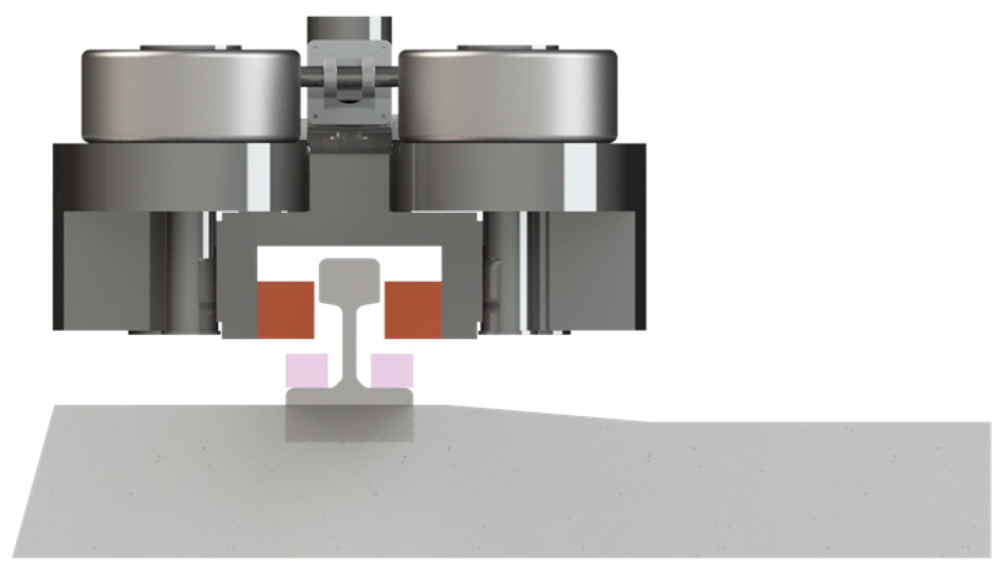
Figure 2.
Example of custom rails adopted in combination with traditional wheeled systems.
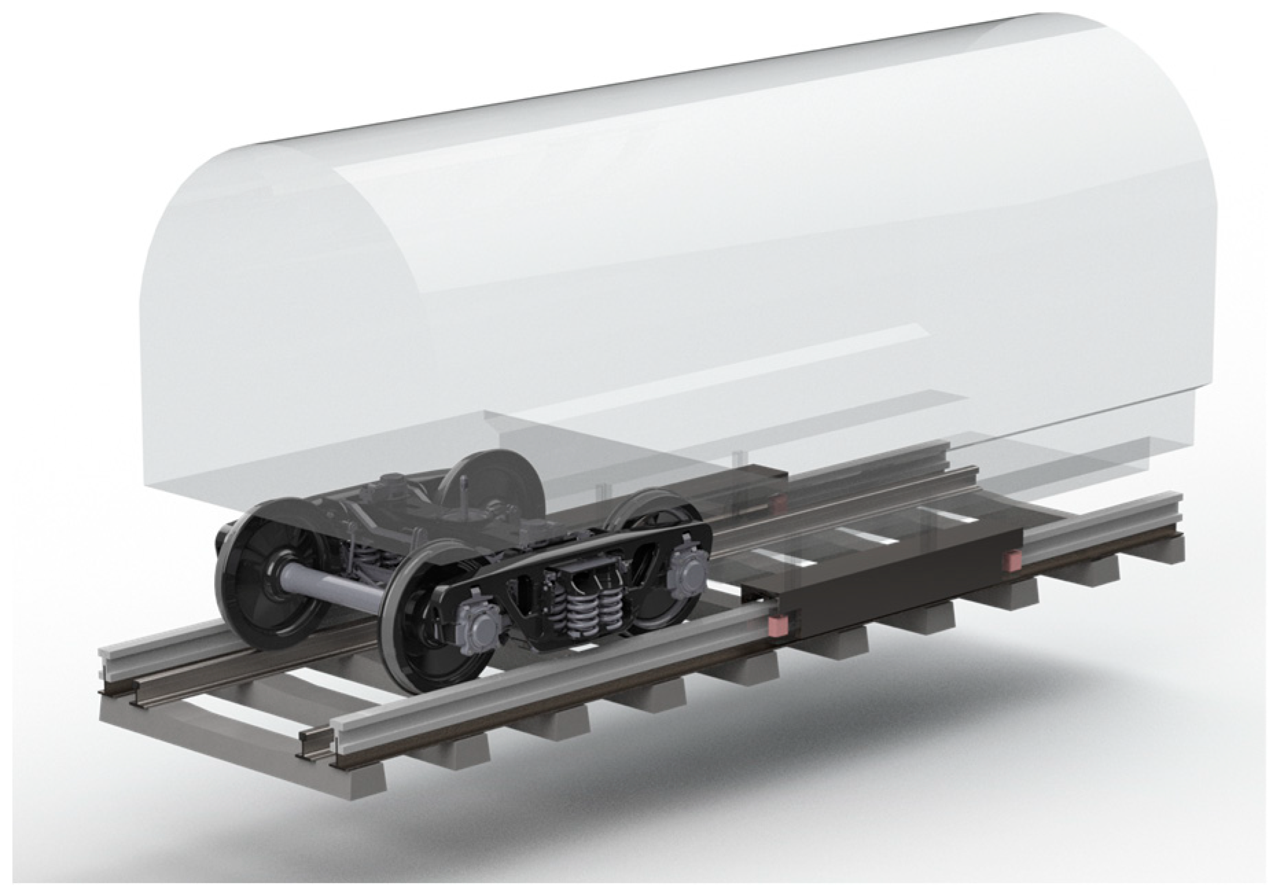
Figure 3.
Example symbolic picture of the MDS components.
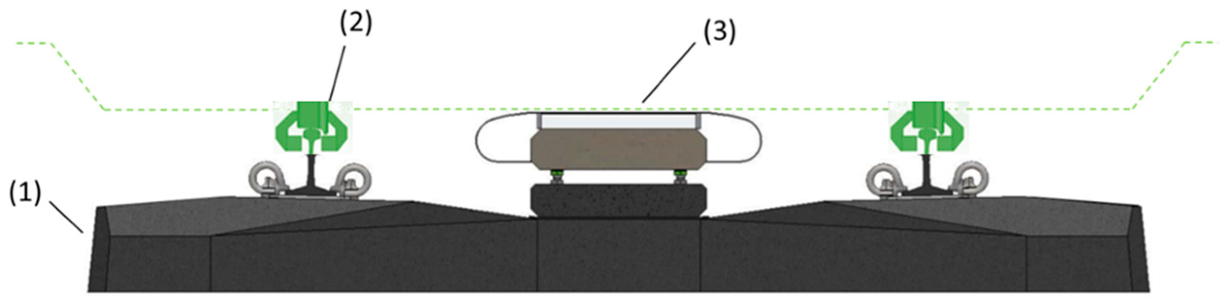
Figure 4.
Schematic of the components of the hybrid MDS.

Figure 5.
Implementing additional cant for MDS vehicles.
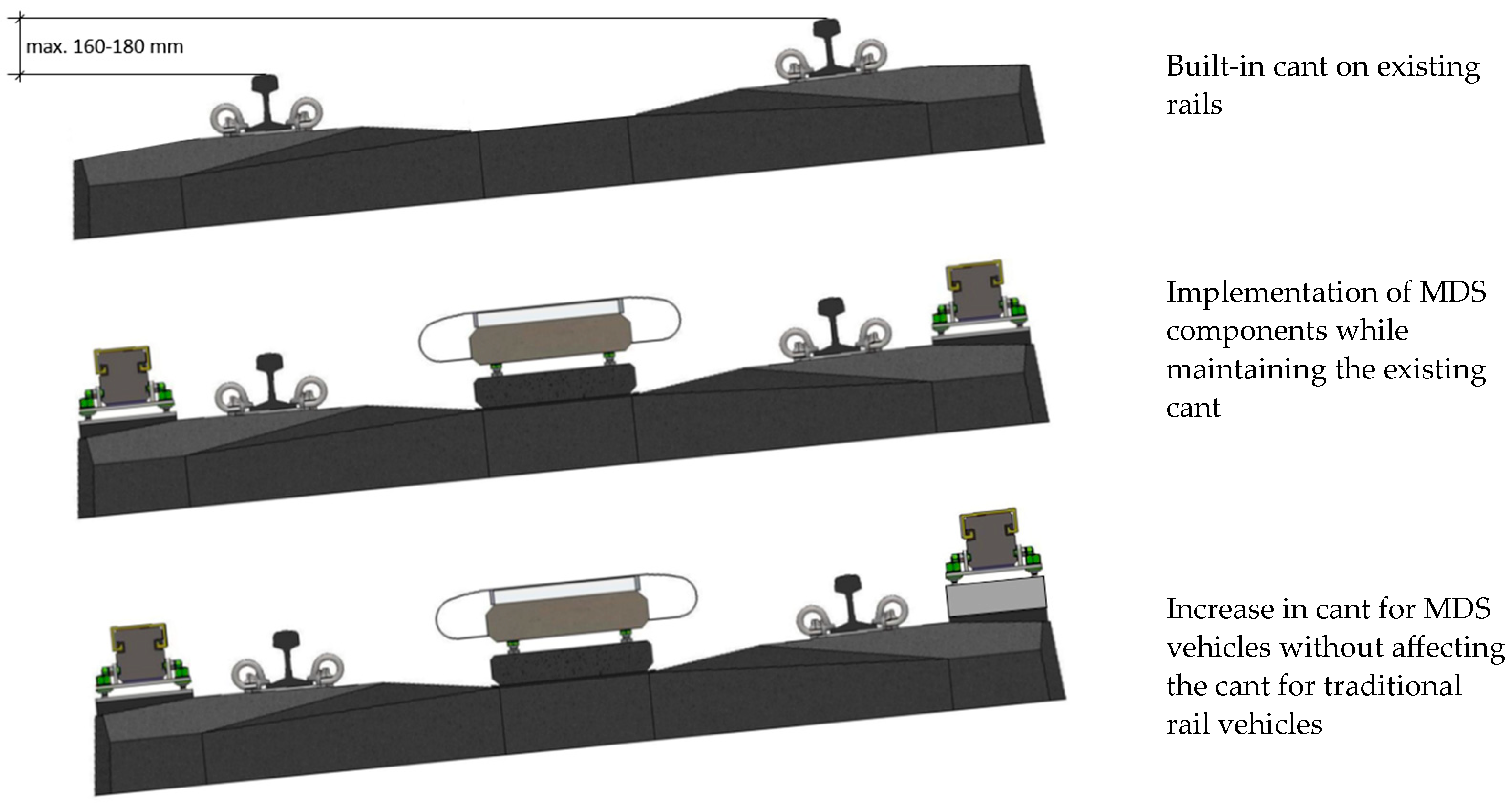
Figure 6.
Power line from the MV grid to the linear motor stator.
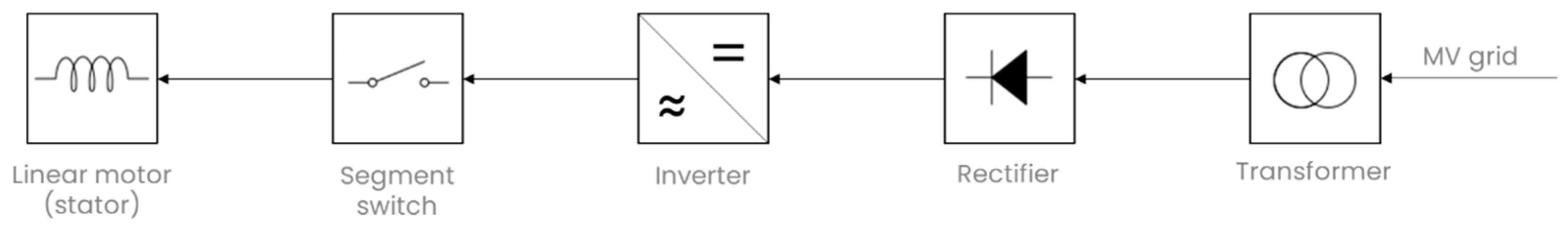
Figure 7.
Linear motor stator division into the sections.
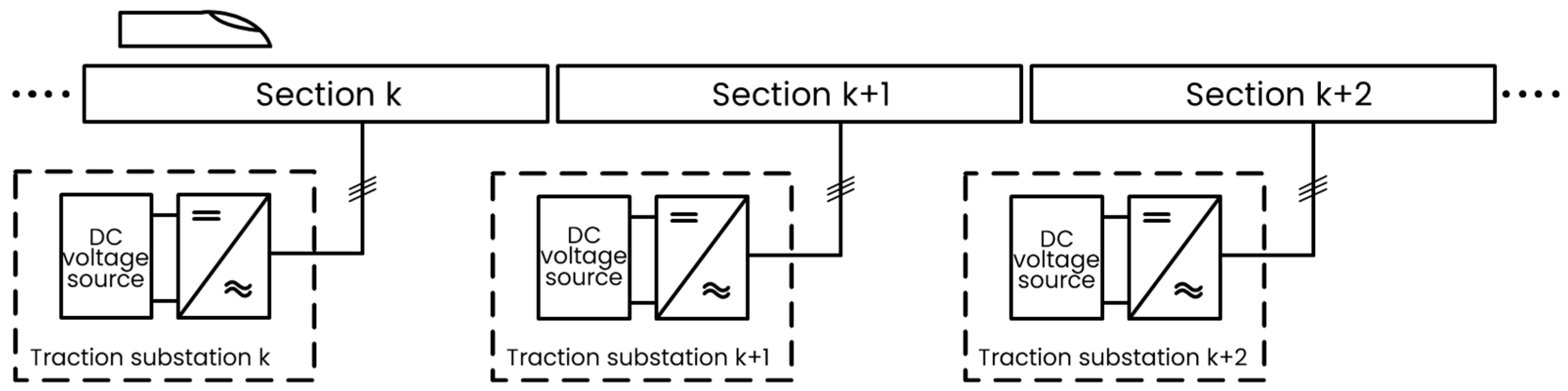
Figure 8.
Pilot line characteristics and main parameters: Speed limitations and vertical alignment with slopes.
Figure 8.
Pilot line characteristics and main parameters: Speed limitations and vertical alignment with slopes.
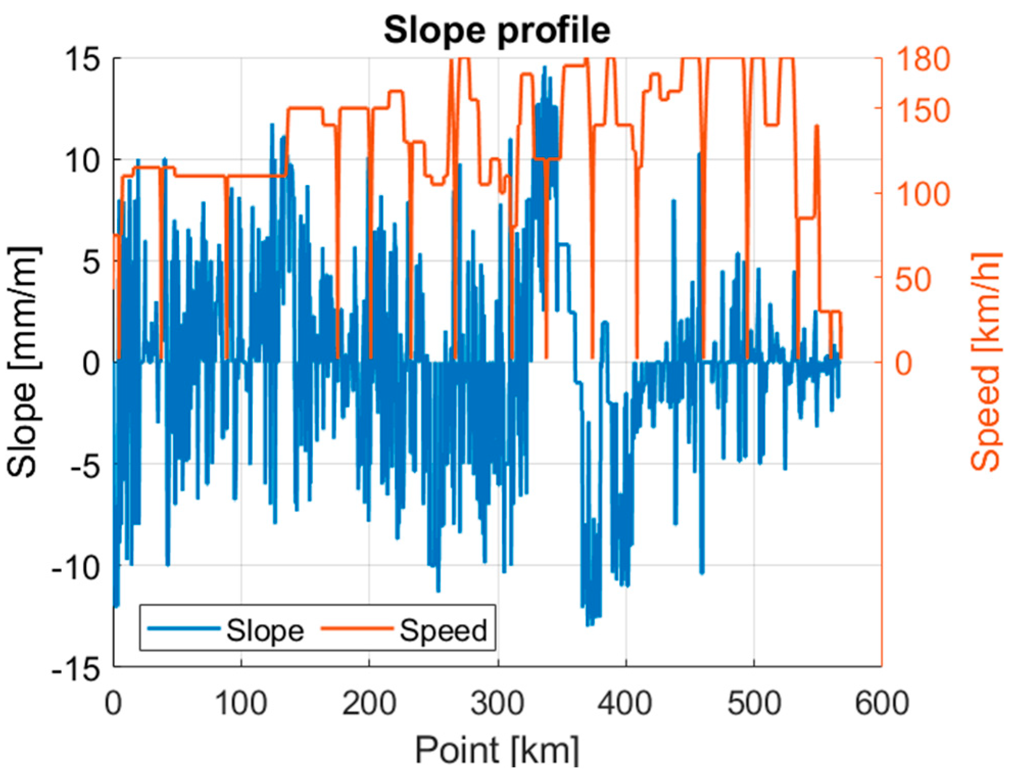
Figure 9.
Relative braking [30].
Figure 9.
Relative braking [30].
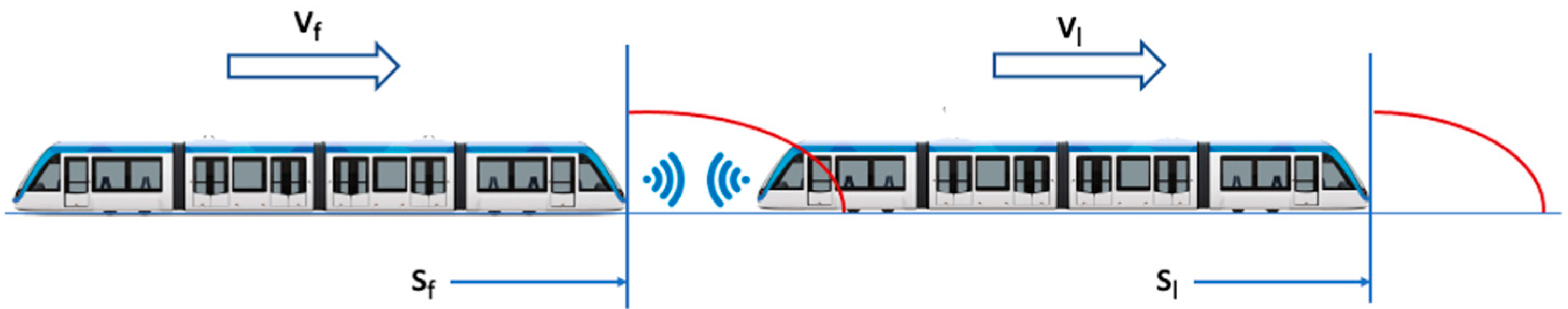
Figure 10.
Flow velocity (m/s) for a single pod composition.
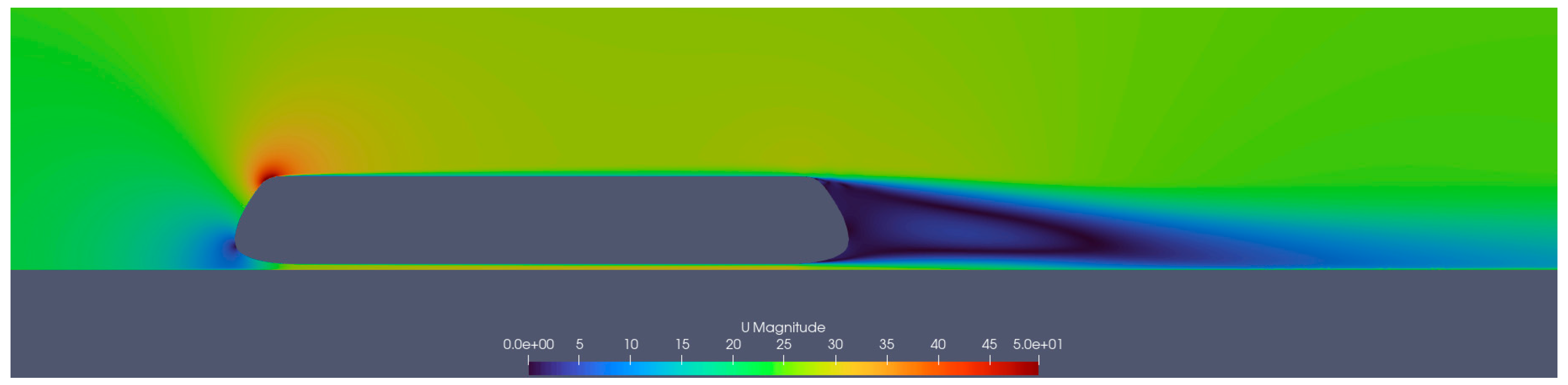
Figure 11.
Pressure distribution (m2/s2) for a single pod composition.
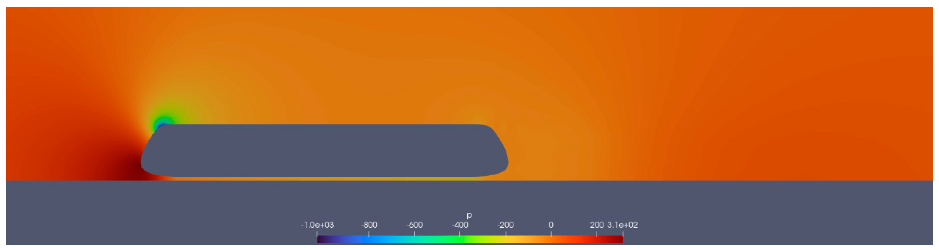
Figure 12.
Flow velocity at 15 m/s for a composition of four pods, (a) with relative braking and (b) with absolute braking.
Figure 12.
Flow velocity at 15 m/s for a composition of four pods, (a) with relative braking and (b) with absolute braking.
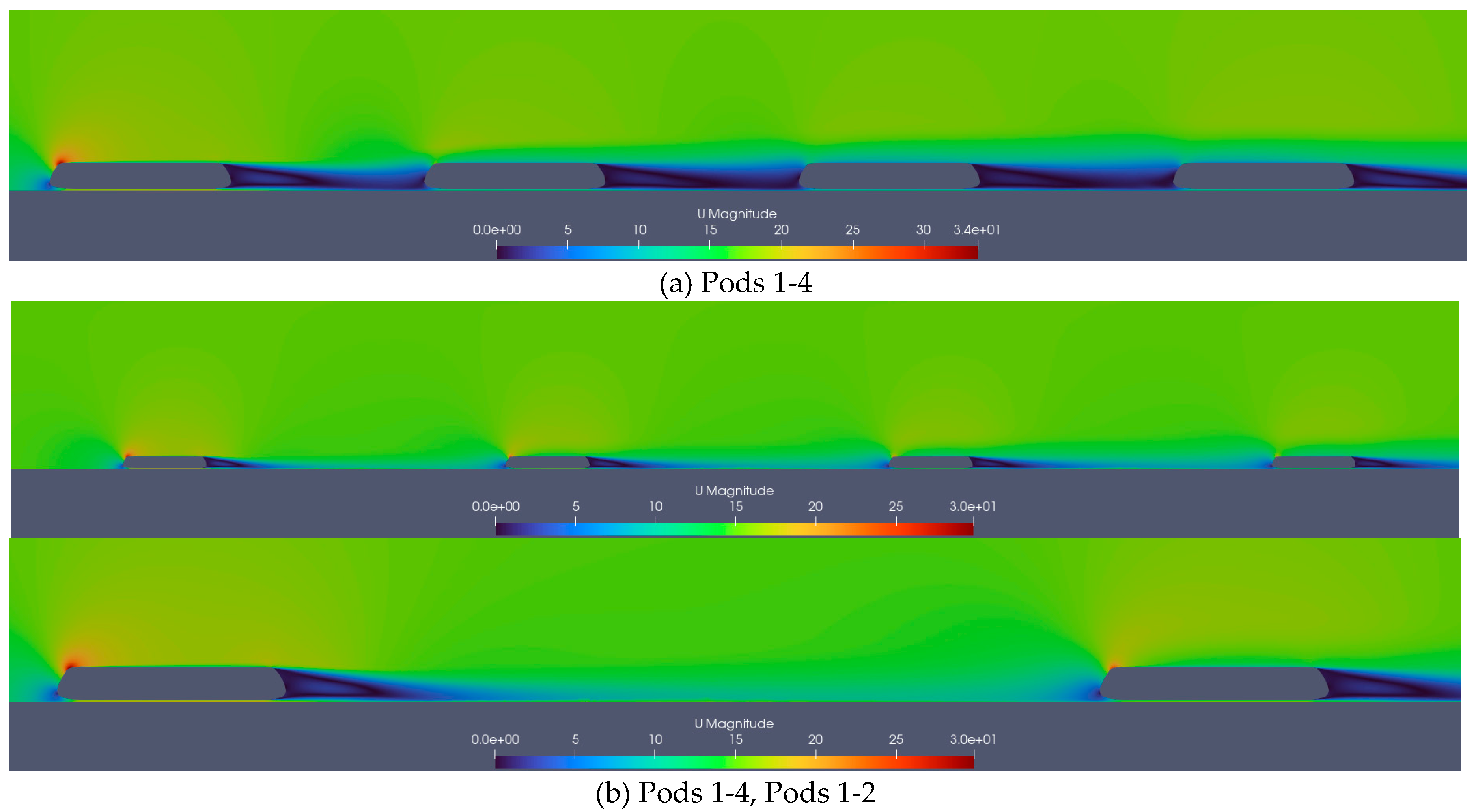
Figure 13.
Cx variation for the different pods.
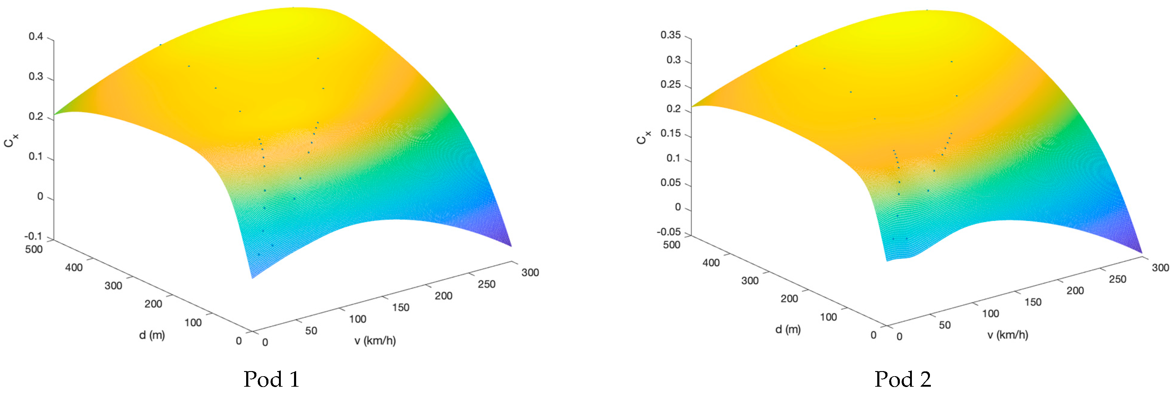

Figure 14.
Line characteristics with two simulation scenarios.
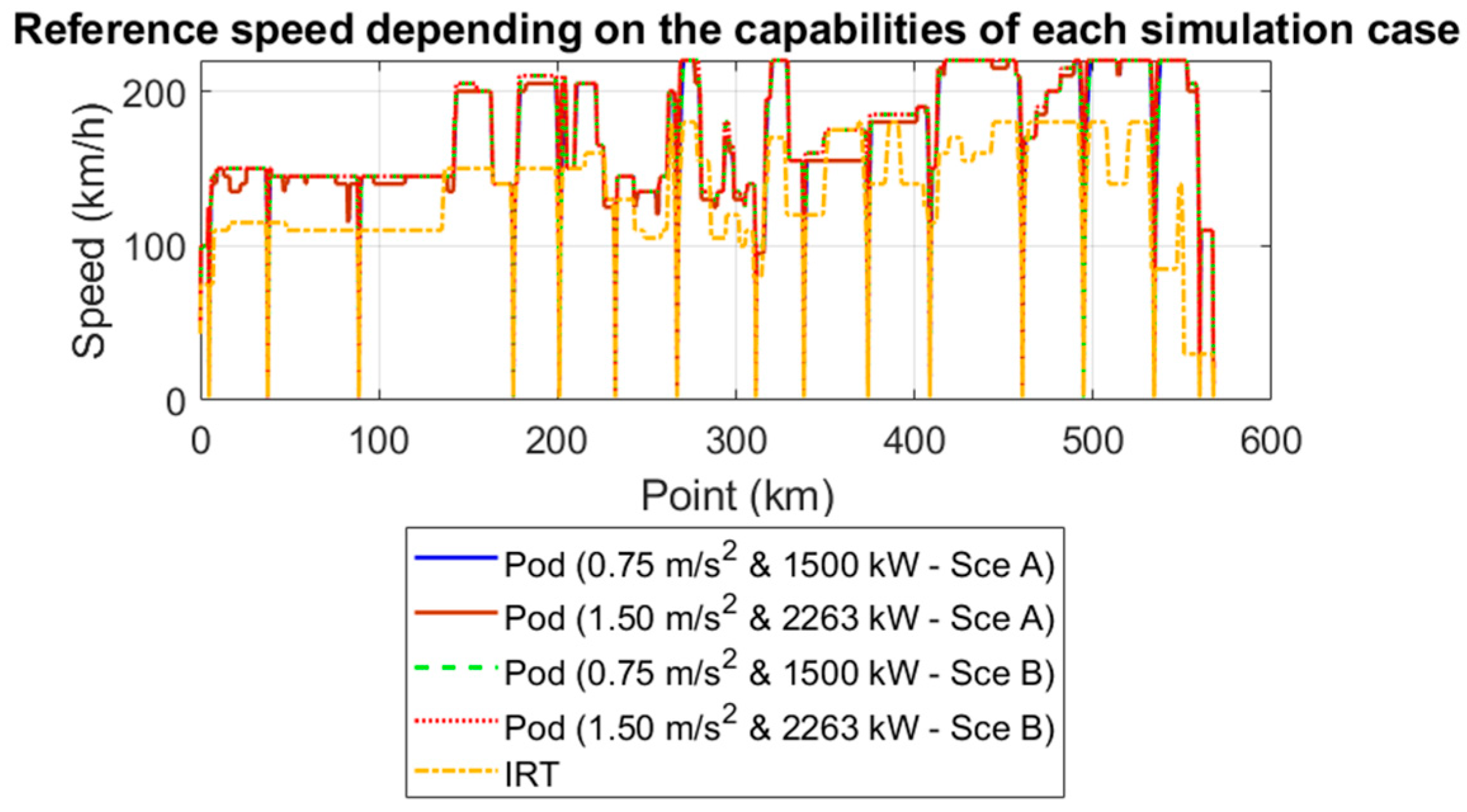
Figure 15.
Time/position diagram for the different trains (stops 3-9).
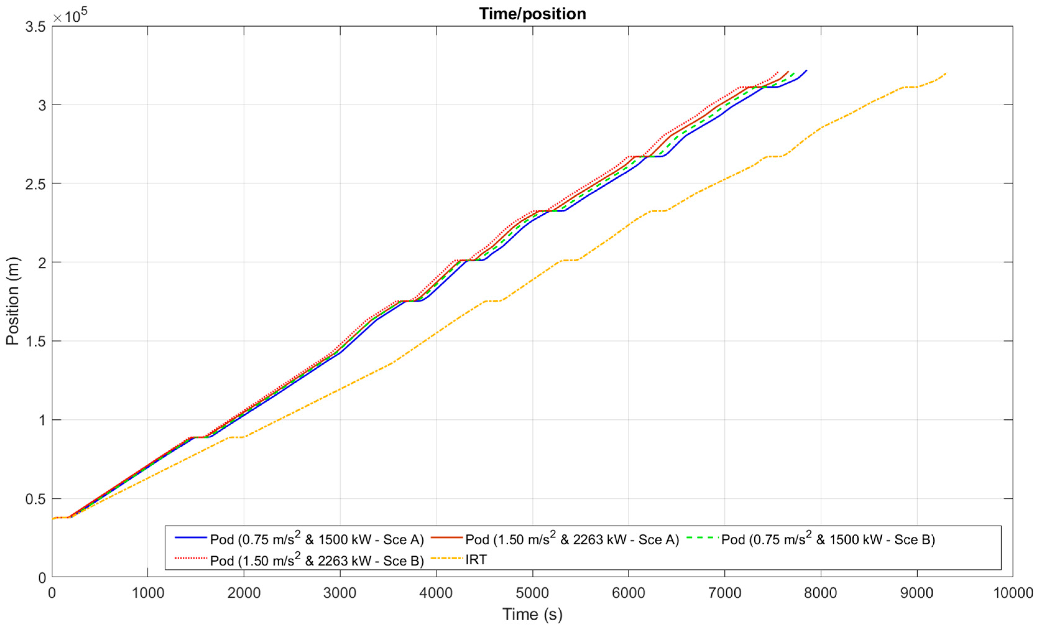
Figure 16.
Speed and longitudinal acceleration for the different trains (stops 3-9).
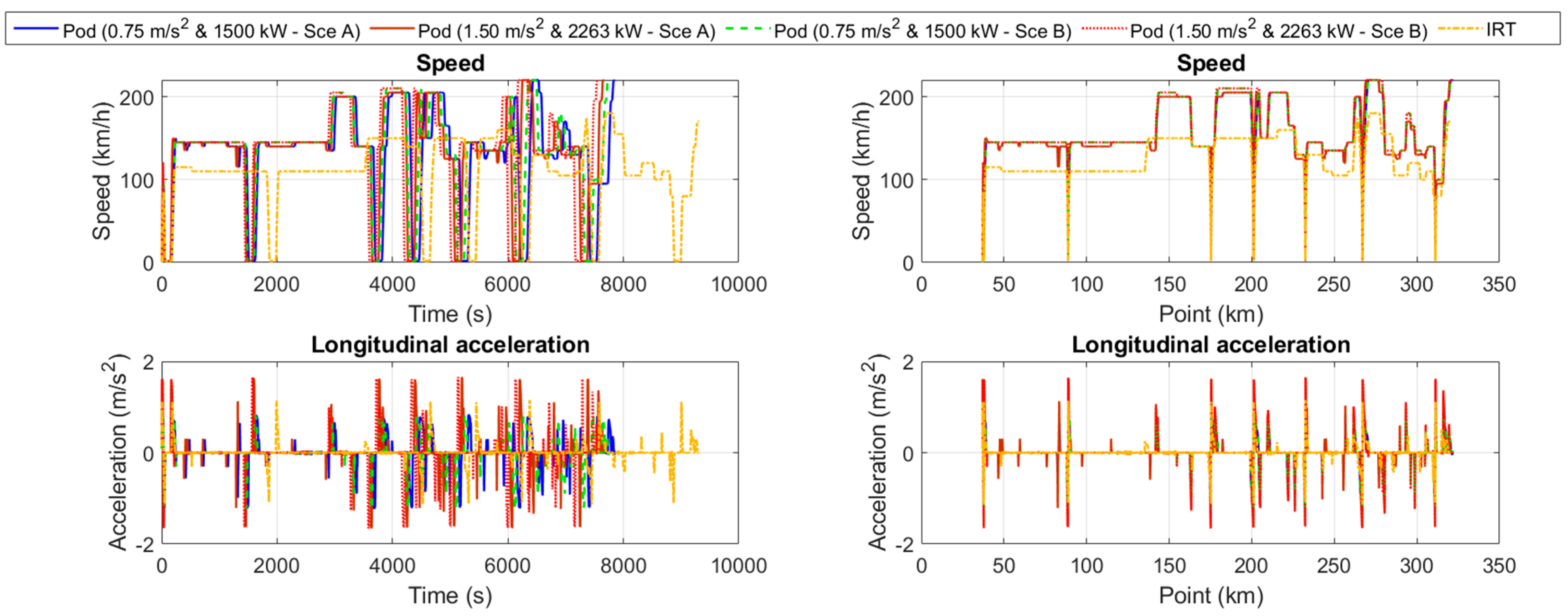
Figure 17.
Traction/braking force and power for the different trains (stops 3-9).
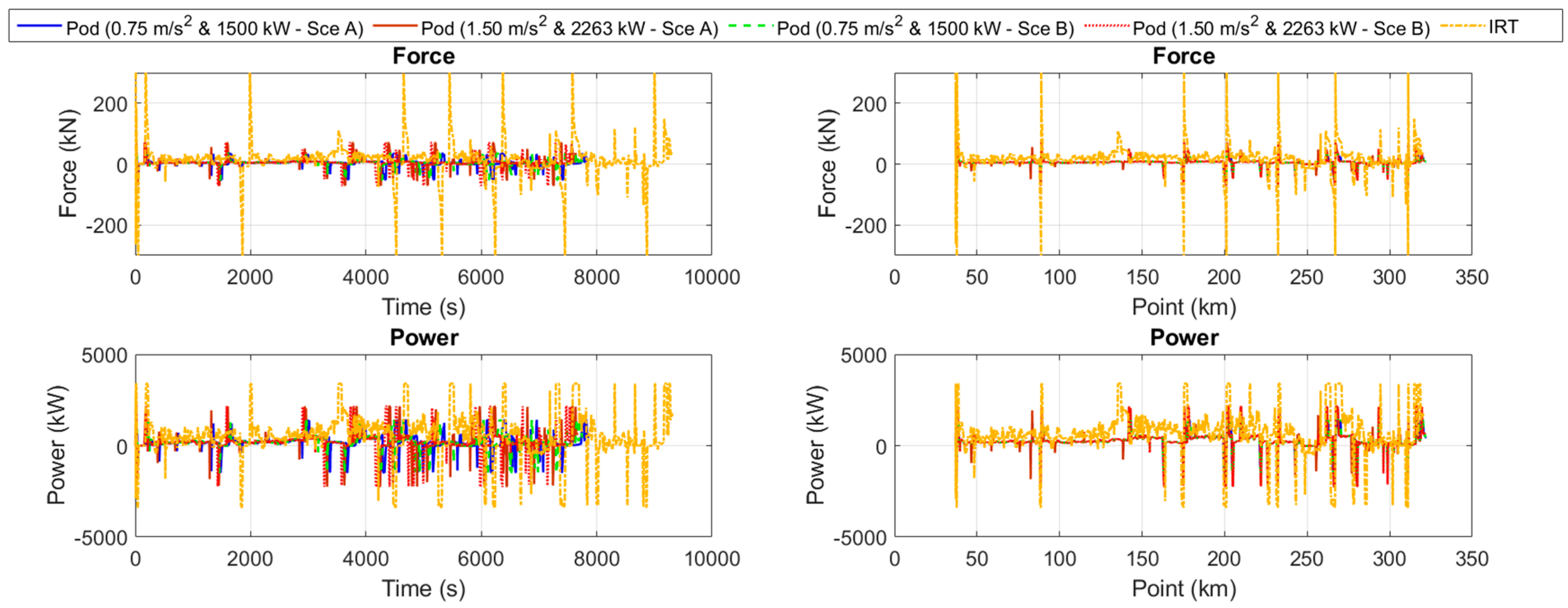
Figure 18.
Traction/braking force and power for the different trains (stops 3-9).
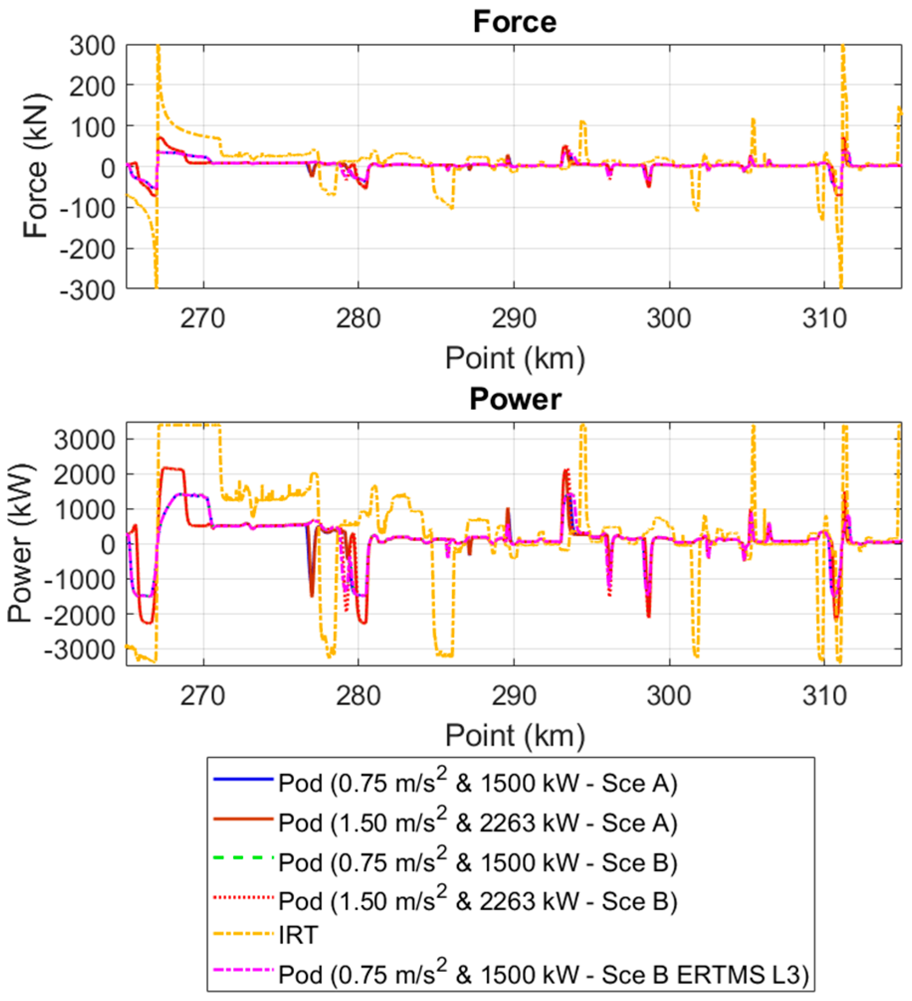
Figure 19.
Energy consumption analysis (only stops 3-9).
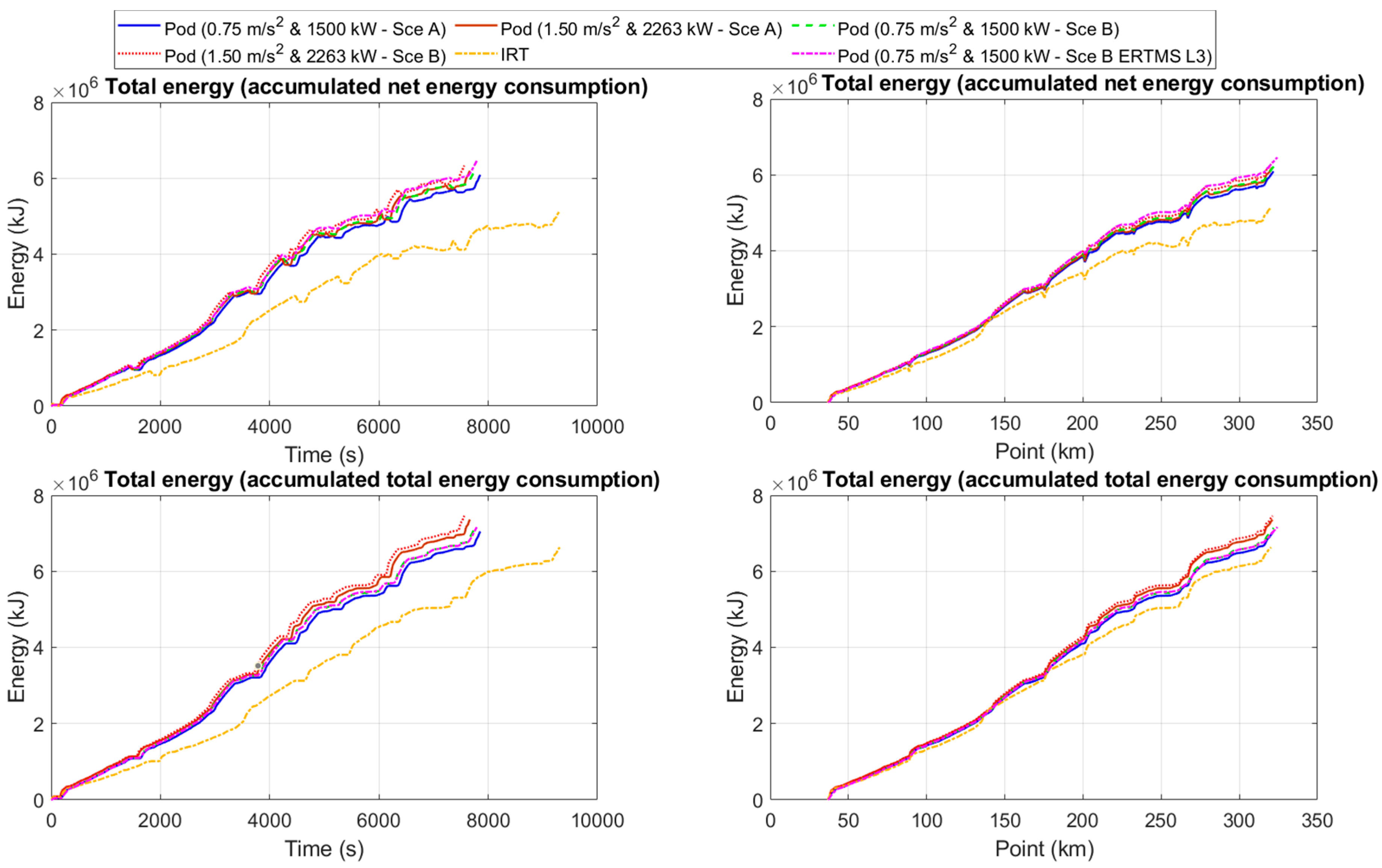

Table 1.
Pilot line characteristics and main parameters.
| Parameter | Value |
|---|---|
| Number of stops | 16 |
| Length: | 550 km |
| Maximum speed: | 180 km/h |
| Max gradient: | 15 ‰ |
Table 2.
IRT to be compared with the new vehicles.
| Parameter | Value |
|---|---|
| Mass: | 268 ton |
| Length: | 110 m (4 coaches) |
| Normal acceleration | 1.1 m/s2 |
| Maximum speed | 180 km/h |
| Power: | 3400 kW |
| Traction/brake maximum force: | +/- 300 kN |
Table 3.
Pods main characteristics.
| Parameter | Value |
|---|---|
| Mass: | 44 ton |
| Length: | 28 m |
| Maximum speed | 220 km/h |
Table 4.
Pods configurations for traction capacities.
| Normal acceleration (m/s2) |
Maximum traction force (kN) |
Power (kW) | Maximum deceleration (m/s2) |
Maximum braking force (kN) |
|---|---|---|---|---|
| 0.75 | 35 | 1500 | 1.2 | 52.32 |
| 1.5 | 71 | 2263 | 1.5 | 71 |
Table 5.
Pods configurations.
| Coefficient | IRT | Pod |
|---|---|---|
| A -N | 1789.79 | 20.3 |
| B -N/(m/s) | 100.18 | 14.1 |
| C-N/(m/s)2 | 8.32 | 2.07 |
Table 6.
Travel time analysis.
| Simulation | Scenario | Travel time | ||
| Absolute value (h) | Reduction (h) | Reduction (%) | ||
| IRT | Current line | 5.39 | 0.0 | 0.0 |
| Pod 0.75 m/s2 | A - V Coupling | 4.13 | 1.3 | 23.4 |
| B - V Coupling | 4.07 | 1.3 | 24.5 | |
| B - ERTMS L3 | 4.34 | 1.0 | 19.4 | |
| Pod 1.50 m/s2 | A - V Coupling | 4.02 | 1.4 | 25.3 |
| B - V Coupling | 3.96 | 1.4 | 26.5 | |
Table 7.
Energy consumption analysis.
| Simulation | Scenario | Energy consumption | Energy consumption (85% recovery) | ||||||
| GJ | kWh | Increase (kWh) | Increase (%) | GJ | kWh | Increase (kWh) | Increase (%) | ||
| IRT | Current line | 13.9 | 3862.3 | 0.0 | 0.0 | 10.4 | 2879.2 | 0.0 | 0.0 |
| Pod 0.75 m/s2 | A - V Coupling | 15.4 | 4268.4 | 406.0 | 10.5 | 13.2 | 3673.0 | 793.8 | 27.6 |
| B - V Coupling | 15.7 | 4361.5 | 499.2 | 12.9 | 13.6 | 3769.6 | 890.4 | 30.9 | |
| B - ERTMS L3 | 17.1 | 4739.2 | 876.9 | 22.7 | 13.8 | 3825.6 | 946.4 | 32.9 | |
| Pod 1.50 m/s2 | A - V Coupling | 16.0 | 4432.7 | 570.4 | 14.8 | 13.4 | 3730.9 | 851.7 | 29.6 |
| B - V Coupling | 16.3 | 4526.6 | 664.2 | 17.2 | 13.8 | 3829.1 | 949.9 | 33.0 | |
Table 8.
Energy consumption analysis.
| Estimated reduction in energy consumption due to aerodynamics | Cx | % |
|---|---|---|
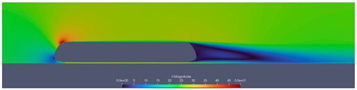 |
0,31 | - |
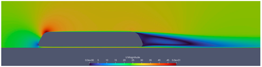 |
0,28 | 9,6 % |
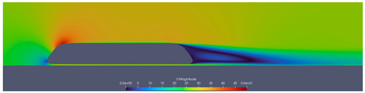 |
0,25 | 19 % |
Table 9.
Different costs used for the CBA.
| Concept | Cost category | Scenario A (m EUR) | Scenario B (m EUR) | |
|---|---|---|---|---|
| Investment Costs | Infrastructure MDS components: Linear motor |
3950 | 3950 | |
| Infrastructure MDS components: Parallel levitation beams |
2860 | |||
| Infrastructure (track alignment, consisting of level crossings elimination) | 15 | 43 | ||
| Infrastructure (signalling) | 57 | 57 | ||
| Infrastructure studies | 0.1 | 0.1 | ||
| Unexpected costs | 141 | 222 | ||
| Rolling stock, including levitation components | 682 | 682 | ||
| Vehicle operational costs | Personnel on Board | 0.0 | 0.0 | |
| Inspection and Cleaning | 17.16 | 17.16 | ||
| Energy | 16.34 | 16.34 | ||
| Operation and Maintenance Costs | Rolling Stock Operation and Maintenance | -51.9 | -51.9 | |
| Infrastructure Maintenance MDS | 91.6 | 153.1 | ||
| Direct Benefits and Externalities | Travel Time Saving | 7020 | 8020 | |
| Vehicle Operation Cost Saving | 1480 | 1480 | ||
| Externalities | 1550 | 1550 | ||
Table 10.
Economic performance indicator results summary.
| Use case | ENPV [m EUR] | B/C | IRR |
|---|---|---|---|
| Scenario A | 1124.11 | 1.31 | 4.67% |
| Scenario B | -1343.87 | 0.78 | 1.39% |
Disclaimer/Publisher’s Note: The statements, opinions and data contained in all publications are solely those of the individual author(s) and contributor(s) and not of MDPI and/or the editor(s). MDPI and/or the editor(s) disclaim responsibility for any injury to people or property resulting from any ideas, methods, instructions or products referred to in the content. |
© 2025 by the authors. Licensee MDPI, Basel, Switzerland. This article is an open access article distributed under the terms and conditions of the Creative Commons Attribution (CC BY) license (http://creativecommons.org/licenses/by/4.0/).
Copyright: This open access article is published under a Creative Commons CC BY 4.0 license, which permit the free download, distribution, and reuse, provided that the author and preprint are cited in any reuse.


