
Submitted:
20 March 2025
Posted:
20 March 2025
You are already at the latest version
Abstract
The selection of composite materials for aerospace applications in extreme environments requires an interdisciplinary approach integrating materials science, structural mechanics and aerodynamics. This study evaluates the suitability of carbon fiber reinforced polymers (CFRPs), glass fiber reinforced polymers and ceramic composites for high temperature, high pressure and radiation exposure conditions [1]. Special emphasis is placed on CFRP composites, in particular KMU-3, which are used in the truss structures of high-altitude pseudo-satellites (HAPS) operating at altitudes of up to 30 km. Mechanical, thermal and aerodynamic properties of CFRP-based structures have been analyzed using finite element methods (FEM), computational fluid dynamics (CFD) and experimental prototyping. The results show that a 0.1 mm thick CFRP shell reduces the mass of the HAPS to 400 kg while maintaining structural integrity against dynamic loads caused by high-altitude turbulence. The study highlights the critical influence of fiber orientation, joint types and additive manufacturing techniques in the development of lightweight and durable aerospace composites [2].
Keywords:
composite materials
; aerospace engineering
; carbon fibers
; truss structures
; finite element analysis
; computational aerodynamics
1. Introduction
The aerospace industry places high demands on structural materials operating under extreme conditions. Aircraft and spacecraft are exposed to rapid temperature changes (from -150°C to +1500°C), high mechanical and vibration loads, aggressive environments and intense radiation [3]. Traditional metallic alloys (titanium, aluminum and nickel based) offer high strength but are limited in lightweight and high temperature applications due to their density and thermal expansion properties [4].
Composite materials based on polymer, ceramic and metal matrix binders offer an optimal combination of strength, stiffness and low density, making them key candidates for aerospace structures [5,6]. High-strength carbon fiber reinforced polymers (CFRPs), such as KMU-3, are widely used in aerospace and rocketry due to their superior fatigue resistance and adaptable mechanical properties [7]. Advanced ceramic composites, such as SiC/SSiC, can withstand extreme temperatures, making them essential for engines and thermal protection systems [8].
However, several challenges still limit the use of composites in aerospace applications. Polymer-based carbon materials are susceptible to micro cracking under cryogenic conditions and are difficult to repair in the field [9]. High-temperature ceramic composites exhibit brittleness that requires structural optimization [10]. In addition, the disposal of composite waste and the development of environmentally friendly bio composites remain pressing issues to reduce environmental impact [11].
This study provides a comparative analysis of different classes of composites with respect to their resistance to extreme aerospace conditions. The article examines mechanical properties, thermal stability and the effects of microstructure and defects on structural durability [12]. The results will provide recommendations for the selection and optimization of composite materials for advanced aerospace applications.
2. Materials and Methods
2.1. Material Selection and Composite Characterization
When designing aircraft for extreme aerospace conditions, particular attention is given to ensuring high structural strength and rigidity while minimizing weight. In the context of this study, one of the primary objectives is to design an unmanned aerial vehicle (UAV), specifically an autonomous aviation apparatus (hereinafter referred to as AAA), capable of operating efficiently at altitudes up to 30 km while maintaining a total weight limit of no more than 400 kg using composite materials. Meeting such mass and strength requirements necessitates materials with high specific strength, thermal resistance, and corrosion resistance [13].
The production of composite parts and components involves a comprehensive process, from sourcing fiber and matrix materials to their processing [14], formation, curing, and subsequent treatment to prepare components for integration into an aircraft. The selection of manufacturing processes is influenced by factors such as component design, material availability, cost, quality, time, expertise, and production volume. A significant portion of costs and resources is allocated to composite development [15], making it a central focus of numerous research and technological projects.
Composite materials are typically composed of fiber-reinforced material [16], such as carbon or glass fiber, which provides strength and stiffness, embedded in a matrix material that ensures overall shape, support, and impact resistance. The properties of a composite depend on the type and composition of the fiber reinforcement and matrix, as illustrated in Figure 1 below.
Among polymer composites, CFRPs stand out for their high specific strength and stiffness, making them indispensable for creating lightweight yet durable structural components. FRPs offer excellent corrosion resistance and lower cost, although they do not match the mechanical strength of CFRPs. Aramid composites, such as Kevlar, are widely used for impact protection due to their high toughness and resistance to mechanical damage. Metal matrix composites (MMCs), such as silicon carbide reinforced aluminum, combine thermal conductivity with strength, making them suitable for thermally stressed components. Ceramic matrix composites (CMCs) are used in applications requiring extreme heat resistance, such as thermal protection systems, although their brittleness requires additional engineering solutions. Hybrid composites, which integrate different fiber or matrix types, allow an optimized balance of properties tailored to specific operating conditions [18,19].
A comparative analysis and classification of traditional metallic alloys, polymers, ceramics and advanced carbon composites is presented in Table 1.
In recent years, CFRPs have gained increasing popularity in AAA-type structures, frequently used in the aerospace industry [20]. These structures employ multilayer composites, optimized through numerical simulations such as Computational Fluid Dynamics (CFD) and Finite Element Method (FEM) [21]. Such multidisciplinary optimization enhances aerodynamic efficiency while simultaneously reducing structural weight.
CFRPs exhibit low density (1.4–1.58 g/cm³) and high strength (400–1200 MPa), making them highly suitable for aerospace applications [22]. However, their field reparability remains limited, necessitating the development of new restoration techniques for damaged components.
Table 2 presents the mechanical properties of various CFRP grades.
As a result, among the available grades (e.g. CMU-1, CMU-1 lm, CMU-9, etc.), carbon fiber reinforced plastic CMU-3 stands out with an optimal balance of properties: high modulus of elasticity (up to 180 GPa along the fibers), high tensile strength (about 1100-1500 MPa) and relatively low density (see Table 3). At the same time, different pipe cross section variants (circular, oval, triangular, etc.) were compared in terms of strength and mass criteria.
The analysis shows that these properties make KMU-3 an attractive choice for the manufacture of rod and shell elements of AAA designed for extreme conditions, including large temperature variations and high aerodynamic loads.
Therefore, considering the modern trends in the aerospace industry and the requirements for weight, strength and operational characteristics of the next generation aircraft, carbon fiber composites [23] (especially KMU-3) appear to be the optimal choice for truss structures and other load-bearing components. These properties, aimed at developing a new generation of composite structures for wings, aircraft engines and propellers, will enable advances in automated application, manufacturing processes, inspection, high temperature resin molding [24], large scale resin infusion and out-of-autoclave curing technologies, among others.
The extensive use of such materials in combination with numerical optimization methods (CFD, FEM) will allow the creation of lightweight, stiff and reliable structures capable of operating in extreme conditions at altitudes of around 30 km and beyond.
2.2. Design of Truss Structure and Technology of Connecting Elements
This section examines the principles of designing composite truss structures for aerospace applications and the joining techniques that ensure structural strength and durability.
Let us begin by defining an AAA. An autonomous aircraft is an aircraft capable of operating without a pilot, using integrated navigation, control and decision-making systems. When selecting a composite material for an AAA, it is essential to consider the operating conditions, loads and weight requirements. The optimal material should provide structural strength, resistance to external factors, and minimal weight to increase flight range and duration.
Figure 2 shows a top view of the truss structure, while Figure 3 shows a side view and a simplified diagram of the bar connections. This truss design allows the external loads to be optimally distributed among the structural elements and significantly reduces weight compared to conventional metallic systems.
To reduce weight while maintaining the required stiffness and strength, a truss structure was chosen [25]. The primary load-bearing elements are thin-walled carbon fiber tubes of various cross-sections, approximately 5 meters long, with a wall thickness of ~0.1 mm.
One of the key challenges in the design of a carbon fiber truss structure is a reliable joining technique for the tubes. Research [26] indicates that fitting based thermal bonding is the most effective method for composite rods. Several critical factors must be considered when using this joining technique: During fabrication, the gap between the parts is minimized. Epoxy resin of the required viscosity is injected into this gap, sometimes with reinforcing fillers (such as short carbon fibers or microspheres), and the entire joint is heat treated (heated to a specified temperature). This process results in complete curing of the resin, forming a monolithic joint with uniform stress distribution. This method is widely used in lightweight and high-strength structures due to the precise part fit and high repeatability of the joint.
Figure 4 schematically illustrates the thermal coupling device, a section of the structural tube and the principle of adhesive injection into the gap. When using such joints, it is essential to ensure accurate part alignment (tolerances for internal diameter and joint length), control the temperature regime and cure time (according to the technical specifications of the epoxy composition), and apply the adhesive evenly to avoid voids or excess resin accumulation.
Adherence to these requirements will prevent delamination and other characteristic damage to the composite material, while also ensuring a high level of fatigue strength.
2.3. Methodology for Calculating Aerodynamic Characteristics (CFD)
Numerical modelling of the aerodynamic characteristics is carried out using CFD. This method allows the prediction of pressure distribution, flow velocity and turbulence around the structure [27]. The core of CFD involves creating a three-dimensional model of the AAA, defining boundary conditions such as flow velocity, pressure and temperature, and generating a finite element mesh for numerical analysis. The key governing equations are the Navier-Stokes equations, which are solved numerically using finite difference or finite volume methods.
In this area, CFD modelling helps to identify critical structural zones, optimize shapes, reduce drag and improve the stability of aircraft under external loads - all without the need for expensive physical testing.
To determine the optimal aerodynamic configurations for the AAA, simulations were performed for several lifting surface designs, including wedge-shaped, delta-wing, and flying-wing configurations with internal truss structures. Three-dimensional CAD models were created for each variant, and the flow dynamics were analyzed using specialized ANSYS Fluent software.
Figure 5 shows an example of a three-dimensional model of the AAA, illustrating its overall geometry and the possible placement of the truss elements.
In general, the solution of the flow problem around an aircraft involves the numerical solution of the Navier-Stokes equations 1 under specified initial and boundary conditions [28].
In the absence of body forces and assuming =const, equations (1) can be written as:
Boundary and initial conditions include no-slip or slip conditions for the velocity vector at solid boundaries, pressure values specified at domain boundaries and flow velocity conditions normal or at an angle to the boundary. In addition, a combination of these conditions can be applied, such as specified pressure and velocity values at the boundary.
The lift force (Y) depends on the circulation of velocity (Γ) and is given by Joukowski's theorem for a wing section of length L (along the span) in a plane-parallel flow of an ideal incompressible fluid equations 2:
where, r - the density of the fluid and u - the free stream velocity.
The circulation (Γ) has the dimension [u × l], and it can be shown that the lift force can be expressed as:
where, S - the characteristic reference area of the body (wing planform area, given by L × b, where b is the chord length of the airfoil); - the dimensionless lift coefficient, which generally depends on aerothermodynamics conditions, including the shape of the body, its orientation in the flow, and the Reynolds (Re) and Mach (M) numbers.
In addition to the lift force, the airfoil also experiences drag force, which can be expressed as:
The drag coefficient and the drag force X primarily consist of four main components:
- -
- Cx, wave (Cx, w) – Wave drag, which appears at Mach numbers close to the critical Mach number (M ≈ 0.8).
- -
- Cx, friction (Cx, tr) – Friction drag, caused by air resistance against the aircraft surface.
- -
- Cx, pressure (Cx, vorticity drag) – Also referred to as vortex drag, resulting from pressure differences around the body.
- -
- Cx, induced (Cx, i) – Induced drag, occurring due to flow deflection, including wingtip vortices and pressure differences between the upper and lower surfaces of the wing.
From equations 3 and 4, the following dependency can be derived equations 5:
where ε - the aerodynamic efficiency.
The results of the numerical simulation of flow velocities around the apparatus are shown in Figure 6.
As a visual representation of the numerical simulation results, Figure 7 shows an example of the study of static and dynamic loads and overloads applied to the aircraft. The Figure 7 shows:
According to the computational experiment, a non-traditional configuration with an optimal angle of attack provides high aerodynamic performance indicators. Additionally, the structural mass is reduced due to the use of carbon fiber tubes, which is particularly significant for high-altitude flights. Similar results were obtained in NASA laboratories, where the advantage of lightweight composite load-bearing systems was emphasized.
As demonstrated above, the only material capable of meeting the stringent requirements for mass and strength under such conditions is carbon fiber reinforced plastic (CFRP). Based on such studies, specific requirements for the properties of composites (elastic modulus, compressive strength limits, impact toughness, etc.) are formulated, which were taken into account in the design of the AAA.
2.4. Calculation of Strength Characteristics (FEM).
This section examines the Finite Element Method (FEM) used to analyze the structural strength characteristics of composite materials. A finite element model has been developed in ANSYS Mechanical to determine the stress-strain state of tubular elements and their connection zones [29,30] (fitting-based thermal bonding). This method allows the simulation of the stress and deformation distribution in composite materials, taking into account the complex loading conditions of the KMU-3 carbon fiber composite, as well as the adhesive in the joints.
The objective is to determine the minimum required wing area (approximately 200 m²) and mass (no more than 400 kg) to meet operational requirements, including powering engines and on-board systems using solar energy, maintaining a reasonable battery reserve (up to 40% of total mass), achieving a cruise speed of 70 m/s, and ensuring a propulsion power of 13 kW with 95% efficiency.
The wing is a thin-walled structure made of KMU-3 carbon fiber composite with a wall thickness of 0.1 mm. For simplicity, the wing shape is assumed to be rectangular with a span of 40 m and a chord of 5 m, giving an area of 200 m². The internal structure is reinforced with a truss system of carbon fiber tubes. The total mass of the wing does not exceed 400 kg, of which up to 40% (160 kg) is accounted for by the solar panels and batteries, evenly distributed over the surface.
Material properties of KMU-3:
- -
- Density: 1450 kg/m³;
- -
- Tensile strength along fibers: 1100 MPa;
- -
- Young's modulus along fibers: 180 GPa;
- -
- Young's modulus across fibers: 9 GPa;
- -
- Shear modulus: 5.1 GPa.
Consideration of operational requirements. The wing must provide sufficient power for the propulsion system, which operates at 13 kW with 95% efficiency, giving an effective power output of approximately 13.7 kW after losses. The solar panels, which cover a significant part of the 200 m² wing area, generate energy during the day, while batteries (weighing up to 160 kg) maintain operation at night. The aircraft achieves a cruise speed of 70 m/s at an altitude of about 30 km, where the air density is extremely low (about 0.018 kg/m³).
The aerodynamic lift force is calculated to ensure stable flight at the specified speed. The lift formula is given by equations 6:
where:
- -
- ρ = 0.018 kg/m³ – air density at an altitude of 30 km;
- -
- V = 70 m/s – cruise speed;
- -
- S = 200 m² – wing area;
- -
- CL = 0.5 – lift coefficient (a typical value for a wing).
Substituting the values:
This force is evenly distributed across the wing and balances the weight of the structure (400 kg × 9.81 m/s² ≈ 3924 N), confirming that a 200 m² wing area is sufficient.
The weight load from the 400 kg mass, including 160 kg of batteries and solar panels, is also distributed across the wing. The total load consists of a combination of aerodynamic lift force and weight force.
For structural analysis, a 3D wing model with a truss structure is created. Thin-walled sections are modeled as shell elements, while the truss system is represented by beam elements. The anisotropic properties of the KMU-3 carbon fiber composite are assigned according to its mechanical characteristics. Boundary conditions include fixing the wing at its attachment points to the fuselage. Loads are applied as distributed aerodynamic forces and weight loads.
Figure 8 shows the 3D models of the selected AAA elements in assembly. The calculation results confirmed that with the correct choice of wall thickness (approximately 0.1 mm) and material (KMU-3), the required strength margin is achieved while maintaining mass and dimensional constraints within 400 kg.
Figure 9 shows the structural solutions of the truss and conventional aircraft configurations and their main geometric and aerodynamic parameters. The diagrams illustrate the main structural elements, such as spars, ribs and stringers, which provide the necessary stiffness and strength of the wing. The main aerodynamic parameters of the wing profiles, such as chord, maximum thickness and maximum curvature, which significantly influence the flight characteristics and efficiency of the structure, are also highlighted.
During the FEM analysis (Figure 10), the stress and deformation distribution was determined for the blade in both traditional and unconventional configurations (delta and rhombic profiles). In addition, the behavior of a tubular element with one end fixed was analyzed (Figure 11). The red and yellow zones indicate areas of maximum stress, while the blue zones correspond to areas of minimum stress. The maximum stress was found to be 37.23 MPa and the minimum stress was 9.9 MPa.
Following the FEM analysis in ANSYS Mechanical, the following characteristics were obtained:
- -
- The maximum stress in the structure is about 50 MPa, which is significantly lower than the tensile strength of the carbon fiber composite (1100 MPa);
- -
- The maximum wing deflection is about 0.5m, which is acceptable for a 40m wingspan;
- -
- The total structural mass is less than 400 kg, including a battery reserve of up to 160 kg.
Finite element analysis confirms that a 200 m² wing with a total mass of no more than 400 kg, made of KMU-3 carbon fiber composite, meets the operational requirements. It can withstand aerodynamic loads at a cruise speed of 70 m/s, power the propulsion system (13 kW) from solar energy and maintain a reasonable battery reserve (up to 40% of total mass). The structure has sufficient strength and stability for flights at altitudes of up to 30 km.
3. Results and Discussion
In this study, KMU-3 carbon fiber composite was identified as the optimal material for a lightweight and durable aircraft structure, combining high mechanical performance with relatively low density. According to calculations performed in ANSYS Mechanical, a wall thickness of approximately 0.1 mm allows the carbon fiber composite to achieve the required density of 1400 kg/m³, while meeting strict weight constraints (not exceeding 400 kg for the unmanned aircraft).
Verification of the weight characteristics after FEM analysis in ANSYS Mechanical confirmed that a shell thickness of 0.1 mm was the optimum choice: further reduction could lead to an unacceptable loss of stiffness, while increasing the thickness would result in excessive weight gain. Based on this, an unconventional AAA configuration was proposed in the form of a truss structure made of thin-walled carbon fiber tubes. This design (Figure 12) allows significant weight reduction while maintaining high structural strength.
Prototypes of tubes and fittings were fabricated to verify the computational models and to determine the mechanical properties of the materials (Figure 13). Tubes made from Kevlar, glass fiber and carbon fiber were produced using 3D printing methods and were later used as the basis for composite fittings. Laboratory tests included tensile, compression, impact and bond strength. The results showed that the strength and stiffness of these joints matched the calculated values and met aerospace structural requirements.
The results obtained confirmed the high fatigue strength of the KMU-3 carbon fiber composite compared to Kevlar and glass fiber, as well as its good compatibility with epoxy resins. This confirms the correct choice of material for the key structural elements of the AAA.
As part of the development of the structural layout, assembly components and containers were designed to house the avionics, power elements, parachute system and a shock-absorbing airbag (Figure 14, Figure 15, Figure 16 and Figure 17). This modular configuration allows the internal structure to be adapted for different missions and operating conditions, while maintaining a predominantly truss-based load-bearing scheme.
Avionics, power elements, parachute storage and deployment, and the impact absorbing airbag Comprehensive Evaluation Results:
- -
- The total mass of the aircraft does not exceed 400 kg, with batteries accounting for up to 40% of the total weight;
- -
- The aerodynamic efficiency of the "flying wing" configuration (delta and rhombic profiles) is in line with the computational predictions, ensuring lift and maneuverability at altitudes up to 30 km.
The results of numerical modelling (CFD, FEM) and prototype testing thus confirm the feasibility of using KMU-3 carbon fiber composite as the primary material for the truss structure. In addition, the chosen unconventional aerodynamic AAA design is proving effective in achieving minimum weight while maintaining the required strength, operational and energy characteristics.
Future plans include extended flight testing and further optimization of structural elements in response to advances in 3D printing technologies, composite bonding and control systems.
4. Conclusions
The selection of composite materials for UAV’s operating in extreme conditions requires detailed analysis. The study showed that KMU-3 carbon fiber composite is optimal for structural components and shells due to its high strength, low density and resistance to delamination. The developed lightweight truss structure, based on thin-walled carbon fiber tubes joined by fitting-based thermal bonding, provides the required strength margin with minimum weight.
CFD analysis confirmed the efficiency of unconventional aerodynamic configurations that help reduce dimensions and structural mass, while FEM modelling identified the possibility of optimizing tube wall thickness and fiber orientation to achieve a target mass of 400 kg. The study took into account aerodynamic loads, self-weight and potential impact and vibration effects.
Laboratory tests showed that the KMU-3 carbon fiber composite outperformed Kevlar and glass fiber in terms of fatigue resistance, and that the epoxy adhesive joints reliably withstood operational loads. The integrated approach, combining computational modelling and experimental testing, improved the accuracy of material selection and optimized the UAV structure.
The results can be applied to the development of next-generation high-altitude pseudo-satellites capable of long-duration loitering at altitudes of 20-30 km.
Author Contributions
Conceptualization, Y.N. and I.F.; methodology, Y.N., A.U. and I.F.; software, I.F.; validation, Y.N., I.F. and A.B.; formal analysis, I.F.; investigation, Y.N., A.U. and I.F.; resources, I.F., A.B. and A.K.; data curation, I.F.; writing—original draft preparation, Y.N.; writing—review and editing, Y.N.; visualization, A.U.; supervision, A.B.; project administration, A.B.; funding acquisition, Y.N. All authors have read and agreed to the published version of the manuscript.
Funding
This research was funded by the Committee of Science of the Ministry of Science and Higher Education of the Republic of Kazakhstan (Grant No. BR218014/0223)
Data Availability Statement
The data generated in this study are presented in the article. For any clarifications, please contact the corresponding author.
Conflicts of Interest
The authors declare no conflicts of interest.
Abbreviations
The following abbreviations are used in this manuscript:
| AAA | Autonomous Aviation Apparatus |
| ANSYS | Engineering simulation software used for FEM analysis |
| CAD | Computer-Aided Design |
| CFD | Computational Fluid Dynamics |
| CMCs | Ceramic Matrix Composites |
| CFRP | Carbon Fiber Reinforced Polymer |
| FEM | Finite Element Method |
| FRP | Fiber Reinforced Polymer |
| HAPS | High-Altitude Pseudo-Satellite |
| Kevlar | A type of aramid composite material |
| KMU-3 | Specific grade of Carbon Fiber Reinforced Plastic used in aerospace |
| MMCs | Metal Matrix Composites |
| NASA | National Aeronautics and Space Administration |
| SiC | Silicon Carbide (ceramic composite material) |
| SSiC | Sintered Silicon Carbide |
| UAV | Unmanned Aerial Vehicle |
References
- Tiwary, A.; Kumar, R.; Chohan, J.S. A Review on Characteristics of Composite and Advanced Materials Used for Aerospace Applications. Materials Today: Proceedings 2022, 51, 865–870. [Google Scholar] [CrossRef]
- ISO/ASTM 52900:2021 Additive Manufacturing — General Principles — Fundamentals and Vocabulary; ISO, 2021.
- Boyer, R.R.; Cotton, J.D.; Mohaghegh, M.; et al. Materials Considerations for Aerospace Applications. MRS Bulletin 2015, 40(12), 1055–1066. [Google Scholar] [CrossRef]
- Zhang, H. , Wu, Y., Wang, K., Peng, Y., Wang, D., Yao, S., & Wang, J. (2020). Materials selection of 3D-printed continuous carbon fiber reinforced composites considering multiple criteria. Materials & Design, 196, 109140.
- Putilina, P.M.; Kutsevich, K.E.; Isaev, A.Yu. Polimernye kompozitsionnye materialy na osnove uglerodnykh i steklyannykh volokon dlya izgotovleniya detalei bespilotnykh letatel’nykh apparatov i perspektivy ikh razvitiya. Trudy VIAM 2023, 8(126), 85–99. [Google Scholar]
- Mishkin, S.I. Primenenie ugleplastikov v konstruktsiyakh bespilotnykh apparatov (obzor). Trudy VIAM 2022, 5 (111), st. 08.
- Barile, C.; Casavola, C.; De Cillis, F. Mechanical Comparison of New Composite Materials for Aerospace Applications. Composites Part B: Engineering 2019, 162, 122–128. [Google Scholar] [CrossRef]
- Katoh, Y. , Snead, L. L., Henager Jr, C. H., Nozawa, T., Hinoki, T., Iveković, A.,... & De Vicente, S. G. (2014). Current status and recent research achievements in SiC/SiC composites. Journal of Nuclear Materials, 455(1-3), 387-397.
- Agrawal, S.; Singh, K.K.; Sarkar, P.K. Impact Damage on Fibre-Reinforced Polymer Matrix Composite – A Review. Journal of Composite Materials 2014, 48(3), 317–332. [Google Scholar] [CrossRef]
- Naslain, R. Design, Preparation and Properties of Non-Oxide CMCs for Application in Engines and Nuclear Reactors: An Overview. Progress in Materials Science 2020, 109, 100736. [Google Scholar] [CrossRef]
- Drupitha, M. P. , Muthuraj, R., Misra, M., & Mohanty, A. K. (2022). Sustainable Biofillers and Their Biocomposites: Opportunities and Challenges. Progress in Polymer Research for Biomedical, Energy and Specialty Applications, 45-72.
- He, X.; Ding, Y.; Lei, Z.; Welch, S.; Zhang, W.; Dunn, M.; Yu, K. 3D Printing of Continuous Fiber-Reinforced Thermoset Composites. Additive Manufacturing 2021, 40, 101921. [Google Scholar] [CrossRef]
- Zhao, K.; Okolo, P.; Neri, E.; Chen, P.; Kennedy, J.; Bennett, G.J. Noise Reduction Technologies for Aircraft Landing Gear – A Bibliographic Review. Progress in Aerospace Sciences 2020, 112, 100589. [Google Scholar] [CrossRef]
- ASTM D3039/D3039M-14: Standard Test Method for Tensile Properties of Polymer Matrix Composite Materials; ASTM International, 2014.
- ASTM D6641/D6641M-16: Standard Test Method for Compressive Properties of Polymer Matrix Composite Materials Using a Combined Loading Compression (CLC) Test Fixture; ASTM International, 2016.
- Chak, V.; Chattopadhyay, H.; Dora, T.L. A Review on Fabrication Methods, Reinforcements and Mechanical Properties of Aluminum Matrix Composites. Journal of Manufacturing Processes 2020, 56, 1059–1074. [Google Scholar] [CrossRef]
- Aerospace Technology Institute. Insight 9: Composites Amended. in-sight_9-composites_amended-2018-09-20.pdf, 2018. [URL].
- Toor, Z.S. Space Applications of Composite Materials. Journal of Space Technology 2018, 8(1), 65–70. [Google Scholar]
- Jayakrishna, K.; Kar, V.R.; Sultan, M.T.; Rajesh, M. Materials Selection for Aerospace Components. Sustainable Composites for Aerospace Applications; Woodhead Publishing, 2018; pp. 1–18.
- Al-Lami, A.; Hilmer, P.; Sinapius, M. Eco-Efficiency Assessment of Manufacturing Carbon Fiber Reinforced Polymers (CFRP) in Aerospace Industry. Aerospace Science and Technology 2018, 79, 669–678. [Google Scholar] [CrossRef]
- Paajanen, A.; Hostikka, S.; Matala, A.; Gutkin, R. CFD-FEA Simulation Framework for Composite Structures in Fire. ECCM16-16th European Conference on Composite Materials, Seville, Spain, 22-26 June 2014, 2014.
- Ozkan, D.; Gok, M.S.; Karaoglanli, A.C. Carbon Fiber Reinforced Polymer (CFRP) Composite Materials, Their Characteristic Properties, Industrial Application Areas and Their Machinability. Engineering Design Applications III: Structures, Materials and Processes, 2020; pp. 235–253.
- Al Azzawi, M.; Hopkins, P.; Ross, J.; Mullins, G.; Sen, R. Carbon Fiber-Reinforced Polymer Concrete Masonry Unit Bond After 20 Years of Outdoor Exposure. ACI Structural Journal 2018, 115(4), 971–982. [Google Scholar] [CrossRef]
- Al-Jaberi, Z.; Myers, J.J.; Chandrashekhara, K. Effect of Direct Service Temperature Exposure on the Bond Behavior Between Advanced Composites and CMU Using NSM and EB Techniques. Composite Structures 2019, 211, 63–75. [Google Scholar] [CrossRef]
- Zhang, X.; Yang, Q.; Yu, R.; Wu, D.; Wei, S.; Cui, J.; Fang, H. Design and Analysis of Truss Aerial Transportation System (TATS): The Lightweight Bar Spherical Joint Mechanism. 2022 IEEE/RSJ International Conference on Intelligent Robots and Systems (IROS); IEEE, 2022; pp. 10501–10507.
- Wang, J.T.; Liu, Y.F.; Liu, X.G.; Yue, Q.R.; Nie, J.G. Photogrammetry-Based Bending Monitoring and Load Identification of Steel Truss Structures. Advances in Structural Engineering 2023, 26(13), 2543–2561. [Google Scholar] [CrossRef]
- Anwar Beg, O.; Islam, B.; Shamshuddin, M.D.; Bég, T.A. Computational Fluid Dynamics Analysis of Moisture Ingress in Aircraft Structural Composite Materials. Arabian Journal for Science and Engineering 2019, 44(9), 7809–7831. [Google Scholar] [CrossRef]
- Temam, R. Navier–Stokes Equations: Theory and Numerical Analysis. American Mathematical Society 2024, 343. [Google Scholar] [CrossRef]
- Rongrong, X.; Zhengyin, Y.; Kun, Y.; Gang, W. Composite Material Structure Optimization Design and Aeroelastic Analysis on Forward Swept Wing. Proceedings of the Institution of Mechanical Engineers, Part G: Journal of Aerospace Engineering 2019, 233 (13), 4679–4695.
- Sun, Z.; Chew, J.W.; Hills, N.J.; Volkov, K.N.; Barnes, C.J. Efficient Finite Element Analysis/Computational Fluid Dynamics Thermal Coupling for Engineering Applications. Journal of Turbomachinery 2010, 132(3), 031016. [Google Scholar] [CrossRef]
Figure 1.
Definition of composite materials [17].
Figure 1.
Definition of composite materials [17].
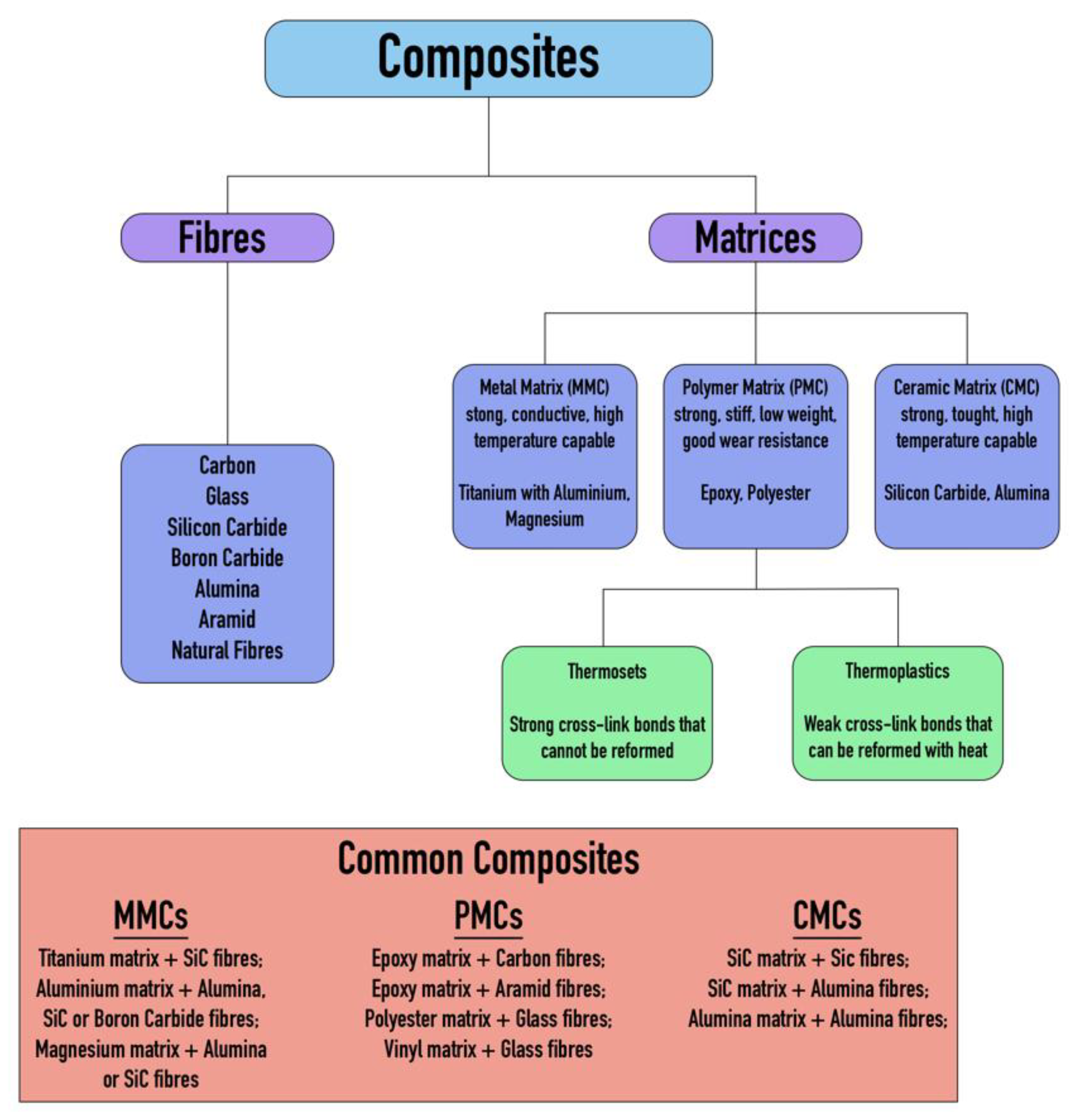
Figure 2.
Truss structure: top view.
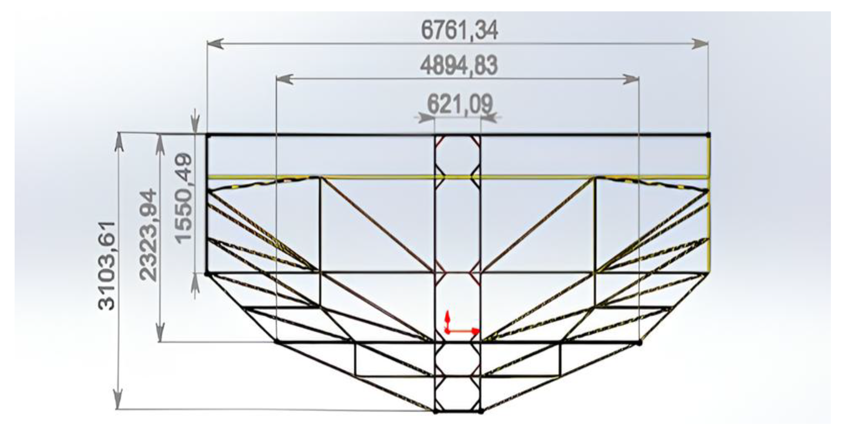
Figure 3.
Truss structure: side view.
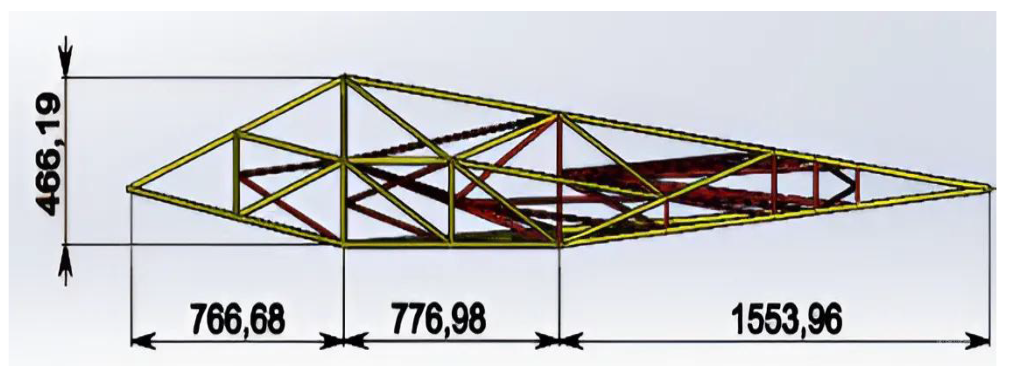
Figure 4.
Coupling, structural tube section and thermal coupling joint of elements.
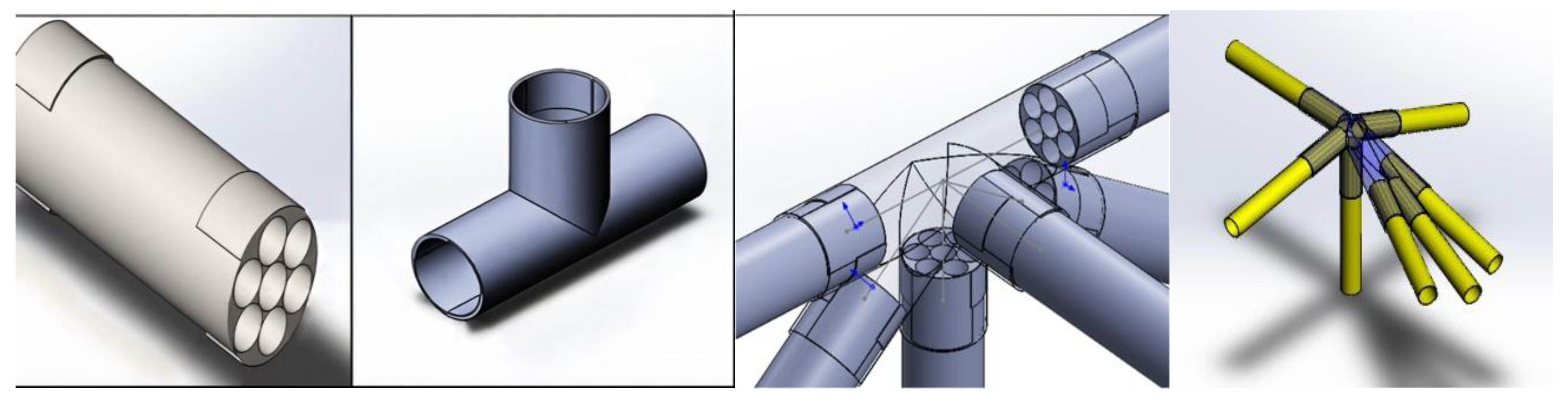
Figure 5.
Solid 3D model of the device.
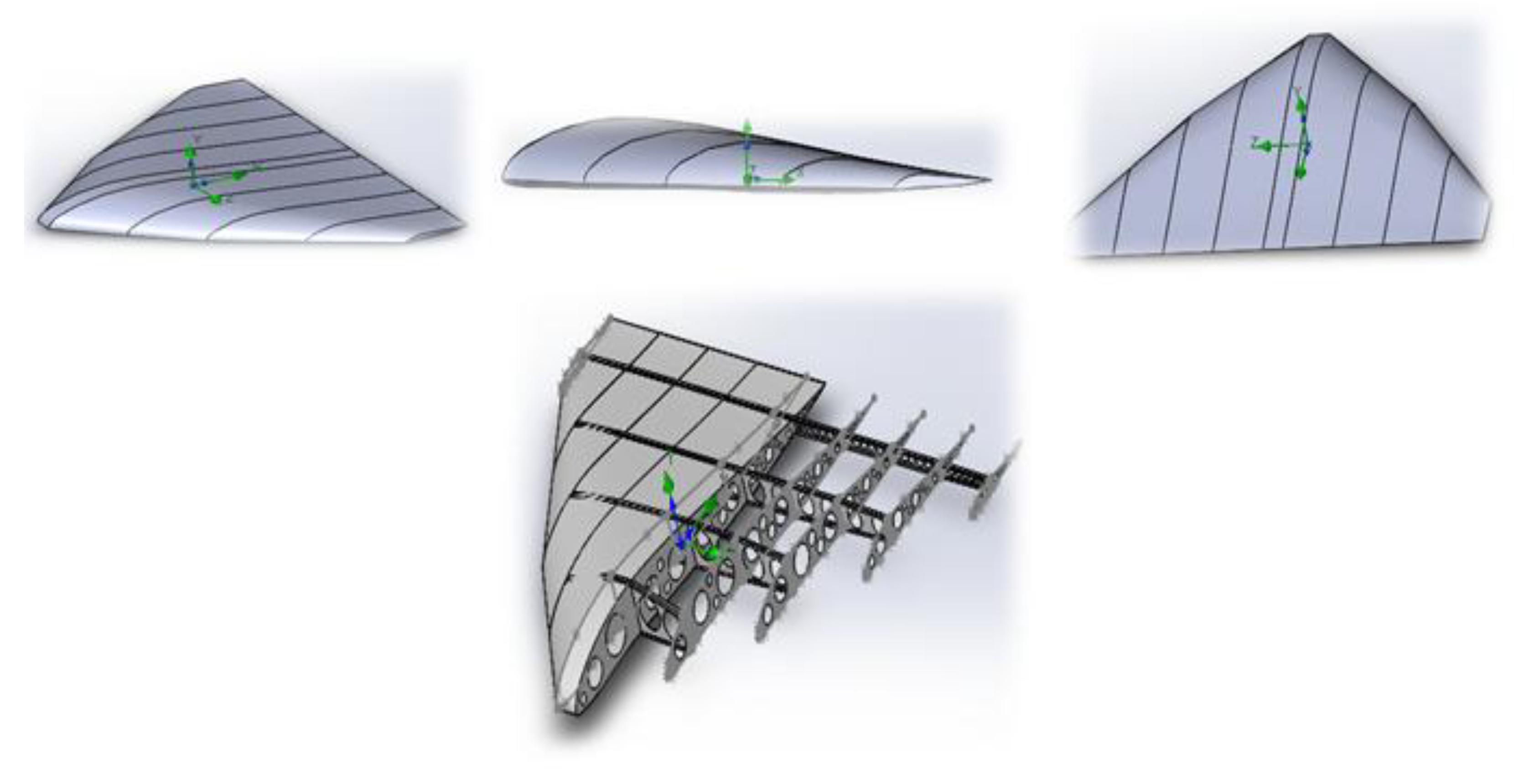
Figure 6.
Numerical simulation of flow velocities around the devices.
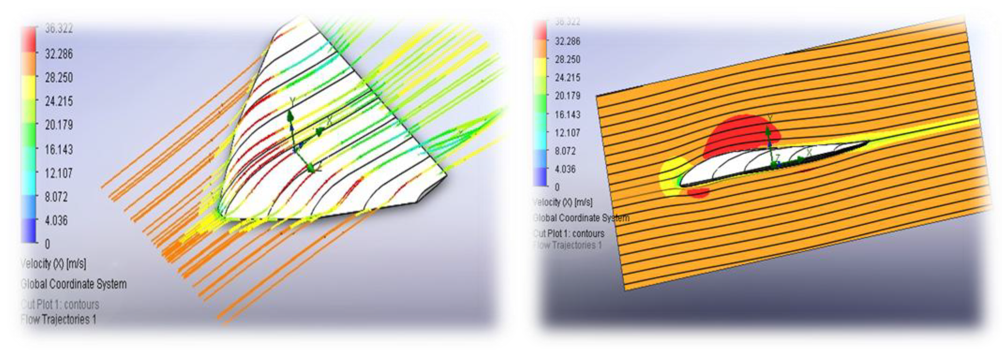
Figure 7.
Study of static, dynamic and overload loads on the aircraft. (a) - pressure distribution; (b) - boundary layer thickness; (c) - turbulence.
Figure 7.
Study of static, dynamic and overload loads on the aircraft. (a) - pressure distribution; (b) - boundary layer thickness; (c) - turbulence.
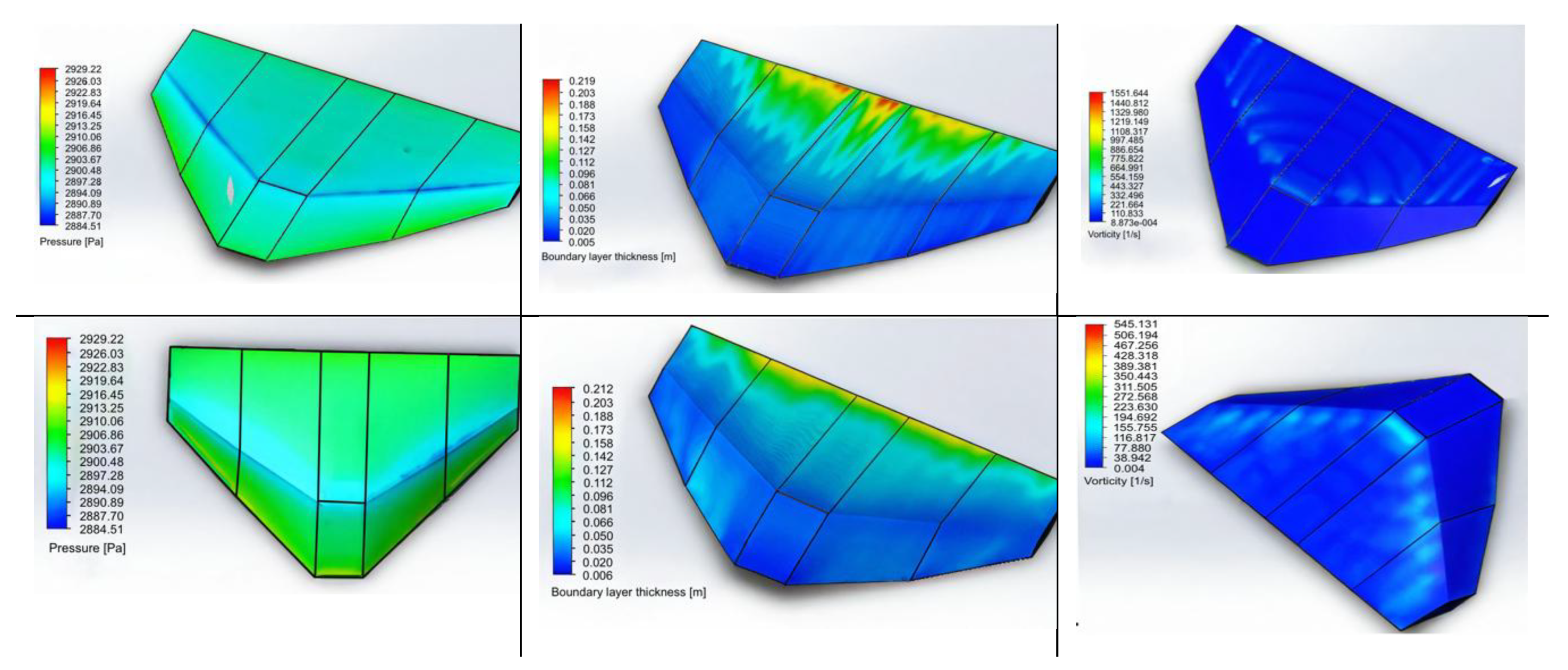
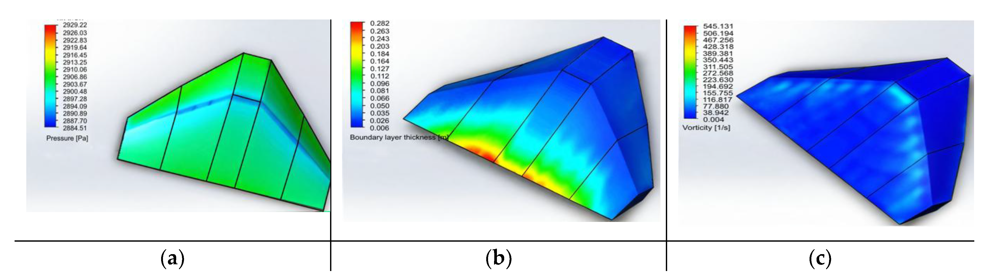
Figure 8.
3D models of AAA elements.
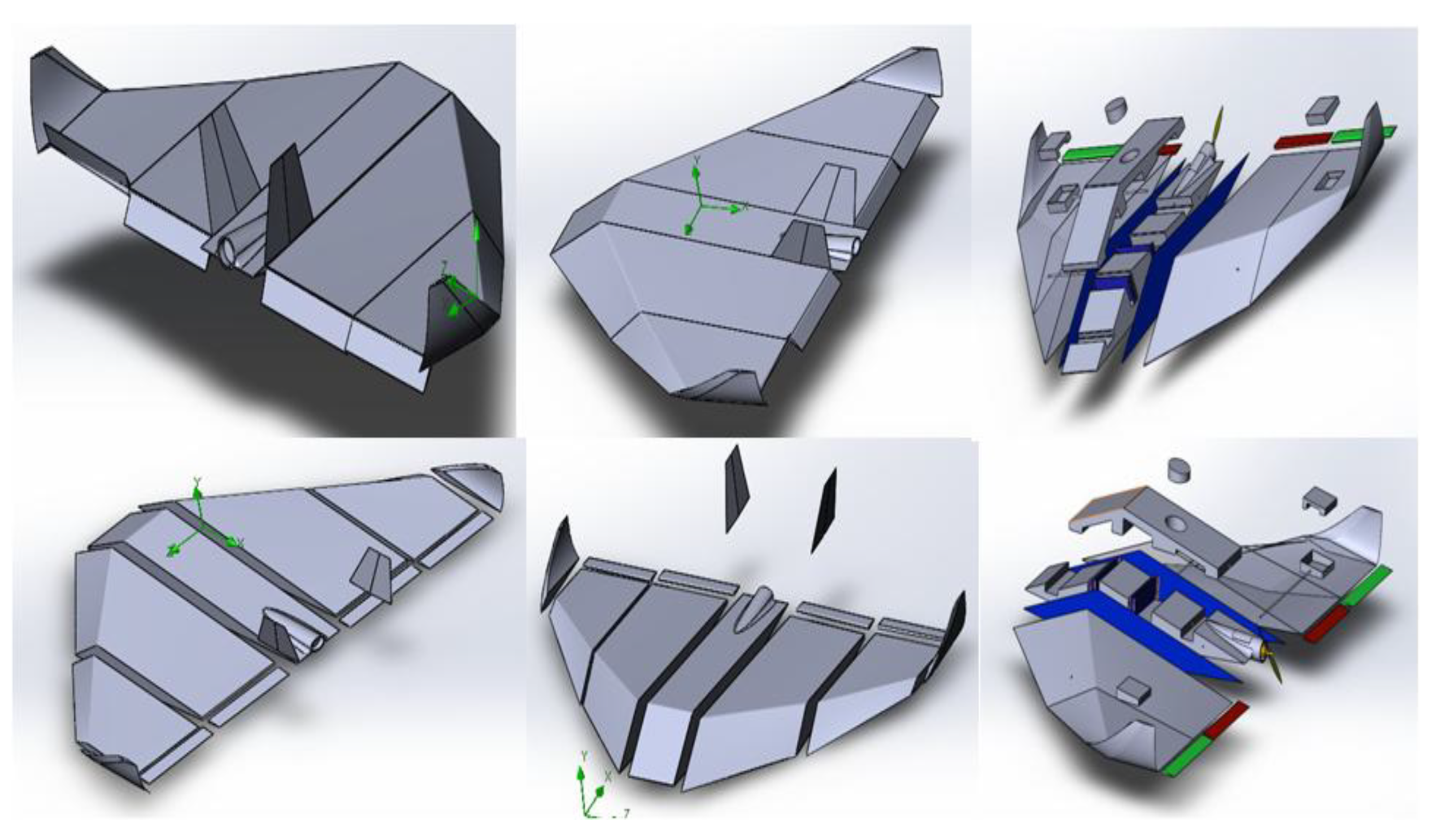
Figure 9.
Structural Design Solutions for Aircraft Configurations with Key Parameters. (a) Truss structure of the aircraft; (b) Profiles of the truss structure with geometric and aerodynamic twist; (c) S-shaped profile for a tailless aircraft.
Figure 9.
Structural Design Solutions for Aircraft Configurations with Key Parameters. (a) Truss structure of the aircraft; (b) Profiles of the truss structure with geometric and aerodynamic twist; (c) S-shaped profile for a tailless aircraft.
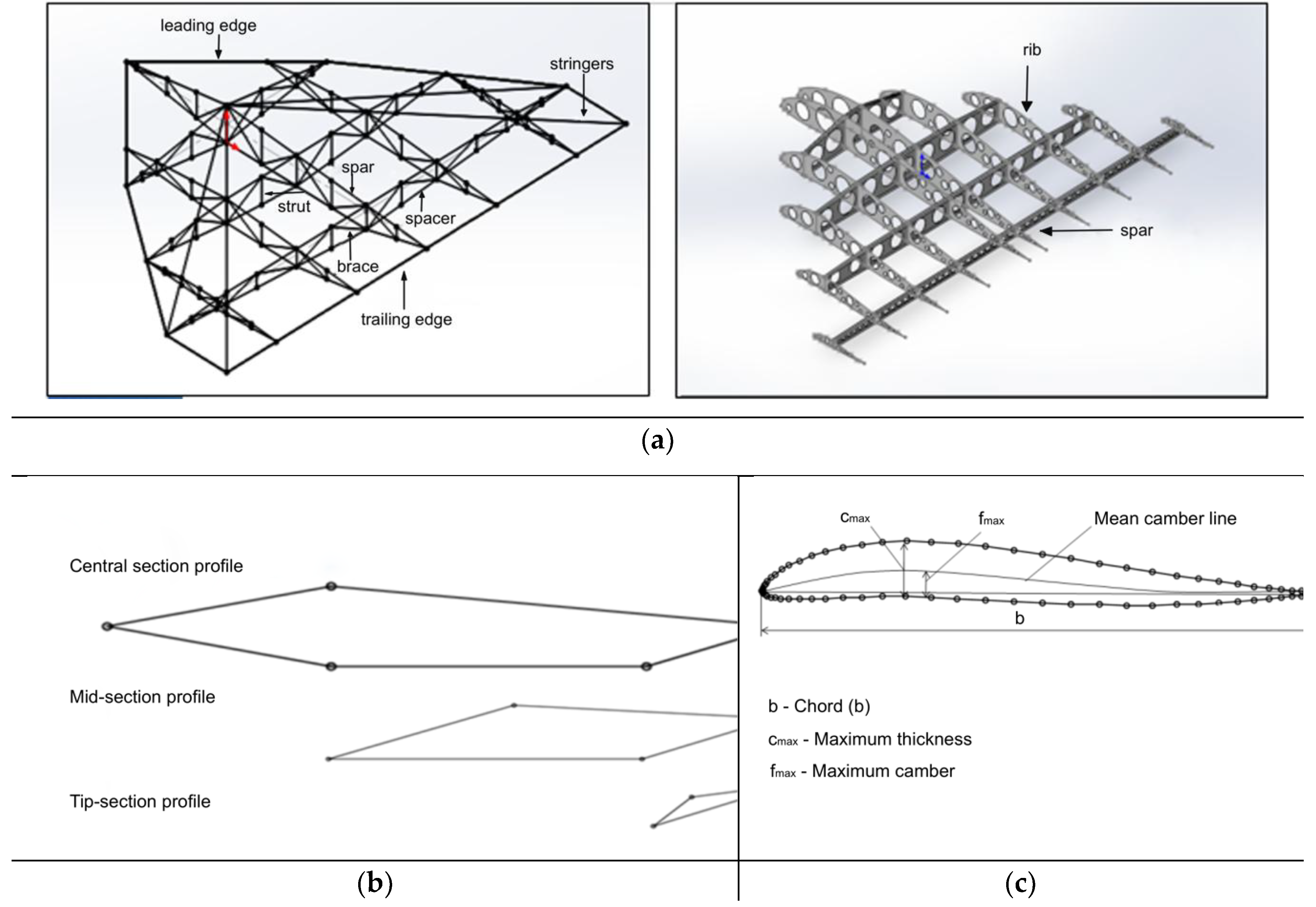
Figure 10.
Simulated Wing: (a) Unconventional and (b) Traditional Configurations.
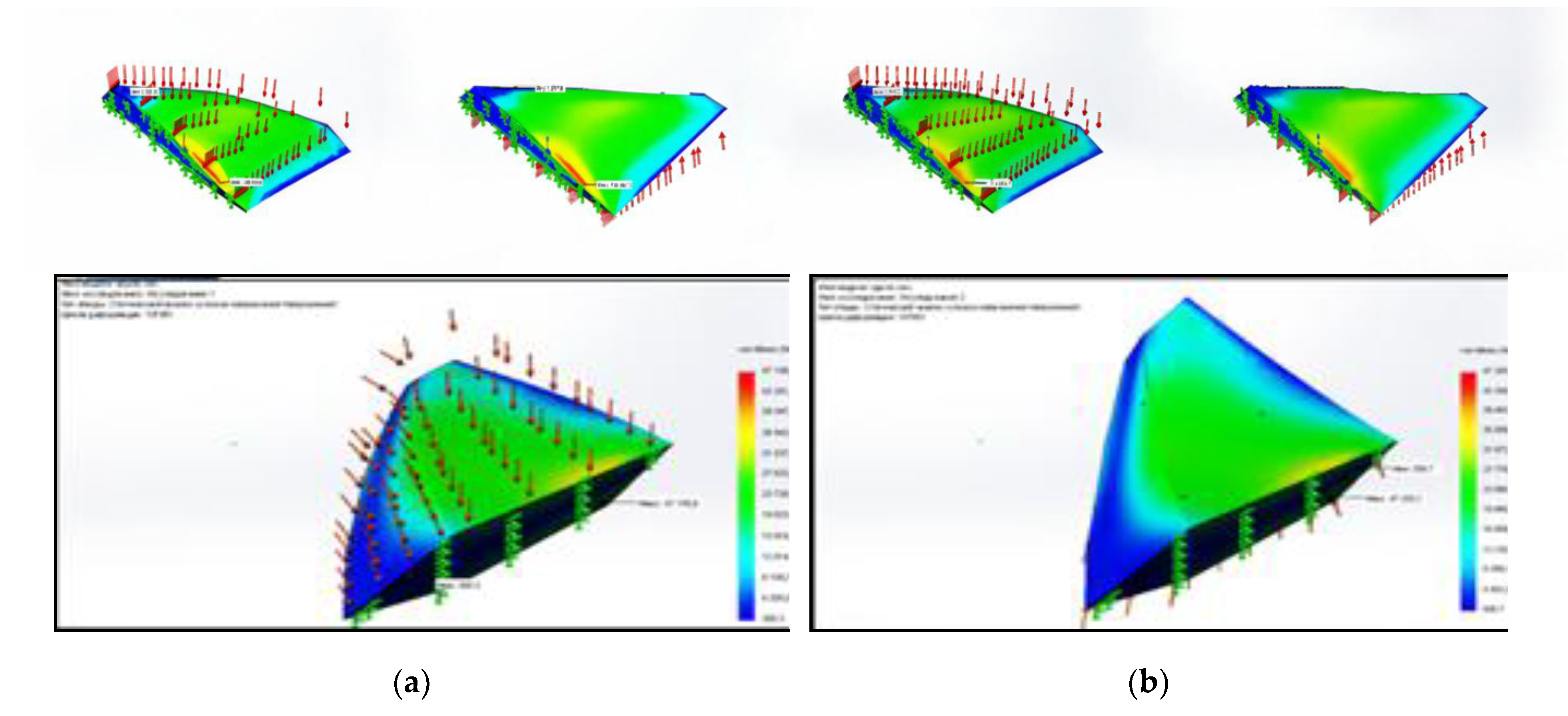
Figure 11.
Stress distribution diagram in a circular section tube with one end fixed.
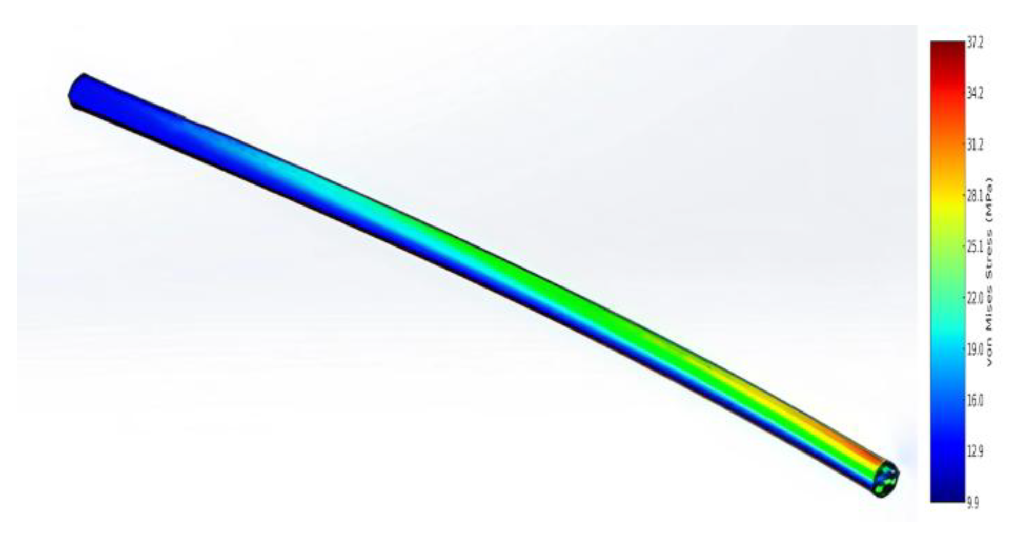
Figure 12.
Structural Configurations of the Wing and Their Physical Parameters. (a) Wing Structural Frameworks; (b) Physical Characteristics of the Structures.
Figure 12.
Structural Configurations of the Wing and Their Physical Parameters. (a) Wing Structural Frameworks; (b) Physical Characteristics of the Structures.
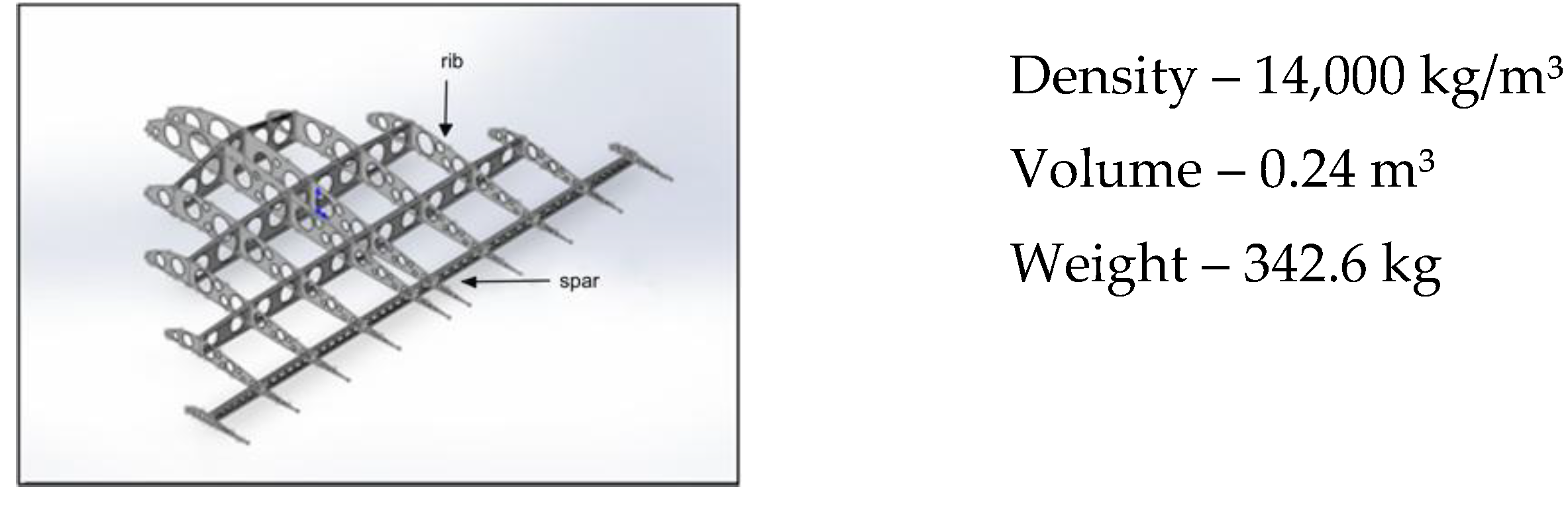
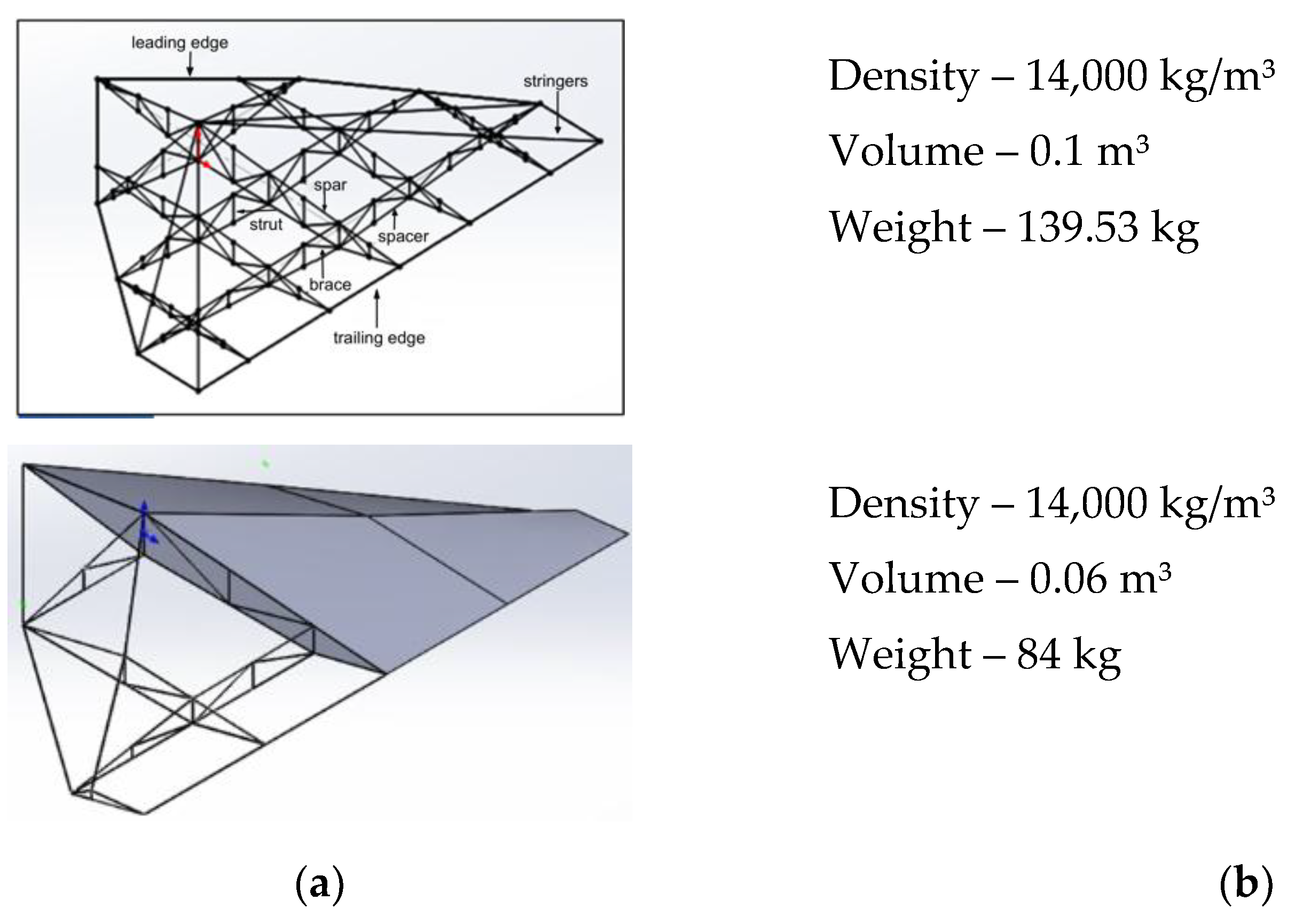
Figure 13.
Samples of Kevlar, glass fiber and carbon fiber tubes for fitting manufacture.
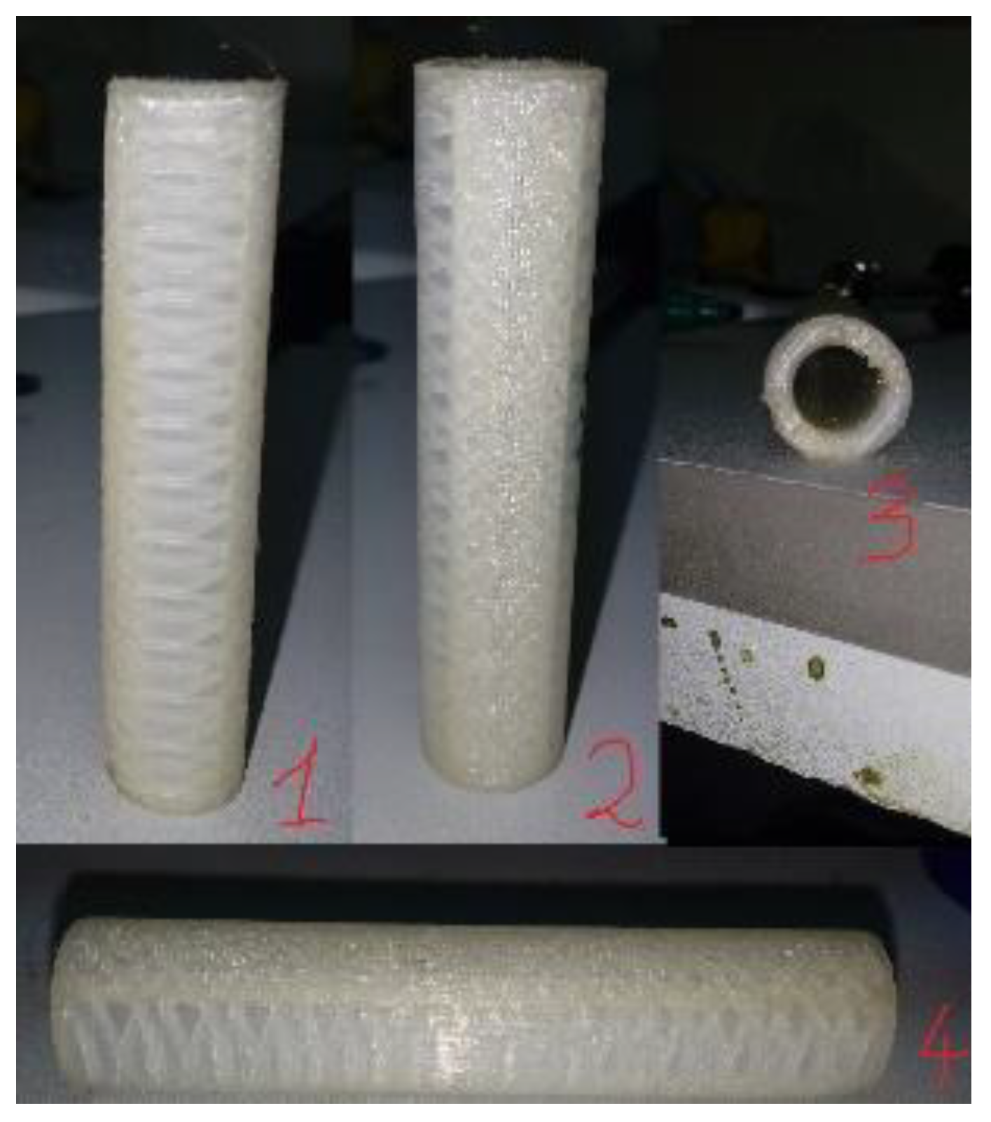
Figure 14.
Structural elements of the AAA.
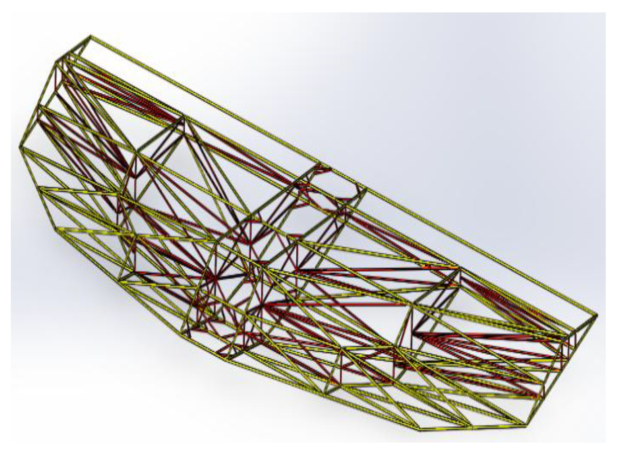
Figure 15.
Laboratory testing of epoxy injected assembly joints.
Figure 16.
AAA structural insert assembly components.
Figure 17.
Assembly components of the insert and canister.

Table 1.
Classification and comparative mechanical properties of composites.
| Material | Polymer Composites | Metal Matrix Composites | Ceramic Composites | Carbon Fiber (CFRP) |
|---|---|---|---|---|
| Tensile Strength (MPa) | 500–1500 | 700–1800 | 800–2500 | 1000–2500 |
| Density (g/cm³) | 1.2–2.0 | 2.5–4.5 | 2.8–3.2 | 1.5–2.0 |
| Thermal Resistance (°C) | Up to 300 | Up to 800 | Up to 1800 | Up to 600 |
| Elastic Modulus (GPa) | 20–150 | 70–200 | 200–400 | 150–300 |
| Wear Resistance (corrosion, fatigue, etc.) | High | Medium | High | High |
| Field Repairability | None | High | High | None |
| Impact Toughness (J/m²) | High | Medium | Low | Variable, depending on application |
| Weight | Very high | Medium to high | Medium | Very low |
| Cost | Very low | Medium to high | High to very high | Medium to very high |
Table 2.
Mechanical properties of different grades of carbon fiber reinforced plastic.
| Parameter | Carbon fiber grade | ||||||||
|---|---|---|---|---|---|---|---|---|---|
| KMU-1 | KMU-1 lm | KMU-3 | KMU-3 lp | KMU-4 l | KMU-4e | KMU-9 | KMU-9t | KMU-9tr | |
| Filter | Bundle VMN-4 | Tape LU-P | Bundle VMN-4 | Tape LU-L | Tape | Tape | Bundle ETF-P | Tape UKN-11/500 | Fabric UOL-300 UT-900-2.5 |
| Matrix | ETF | ETF-M | 5-211B | 5-211B | ENFB | ENFB | UNDF-4A | UNDF-4AR | UNDF-4AR |
| Fiber Volume Content (%) | 57-63 | 58-63 | 57-63 | 50-55 | 50-55 | 54-59 | 60-62 | 58-62 | 55-59 |
| Density(kg/m3) | 1,45-1,49 | 1,48-1,50 | 1,4-1,45 | 1,4-1,45 | 1,45-1,50 | 1,49-1,52 | 1,55-1,58 | 1,52-1,56 | 1,52-1,54 |
| Tensile Strength (MPa) - Along Fibers | 1020 | 780 | 1100 | 730 | 800 | 900 | 1500 | 1500 | 60 |
| Tensile Strength (MPa) - Across Fibers | 14 | 18 | 23 | 20 | 24 | 32 | 32 | 28 | 60 |
| Compressive Strength (MPa) - Along Fibers | 400 | 580 | 700 | 530 | 750 | 900 | 1200 | 1200 | 60 |
| Compressive Strength (MPa) - Across Fibers | 100 | 130 | 150 | 120 | 130 | 130 | 140 | 160 | 58 |
| Shear Strength Along Fibers (MPa) | 30 | 61 | 40 | 54 | 70 | 78 | 85 | 78 | 52 |
| Tensile Modulus (GPa) - Along Fibers | 180 | 145 | 180 | 147 | 140 | 125 | 140 | 125 | 67 |
| Tensile Modulus (GPa) - Across Fibers | 9 | 9,9 | 10 | 9,9 | 10 | 8 | 9 | 8 | 67 |
| Shear Modulus (GPa) | 3,5 | 4,5 | 5,1 | 5,1 | 6,0 | 6,5 | 6,8 | 5,2 | 8,0 |
Table 3.
Data on structural elements of an aircraft with a wedge-shaped wing profile, in particular on tubes with a length of 5 meters.
Table 3.
Data on structural elements of an aircraft with a wedge-shaped wing profile, in particular on tubes with a length of 5 meters.
| Tubes (5m) | Mass (kg) | Surface Area (m²) | Density (kg/m²) |
|---|---|---|---|
 |
1.81 | 1.23 | 1400 |
 |
0.37 | 1.51 | |
 |
0.93 | 1.S4 | |
 |
2.16 | 1.43 | |
 |
1,40 | 1.53 | |
 |
1.99 | 1.11 |
Disclaimer/Publisher’s Note: The statements, opinions and data contained in all publications are solely those of the individual author(s) and contributor(s) and not of MDPI and/or the editor(s). MDPI and/or the editor(s) disclaim responsibility for any injury to people or property resulting from any ideas, methods, instructions or products referred to in the content. |
© 2025 by the authors. Licensee MDPI, Basel, Switzerland. This article is an open access article distributed under the terms and conditions of the Creative Commons Attribution (CC BY) license (http://creativecommons.org/licenses/by/4.0/).
Copyright: This open access article is published under a Creative Commons CC BY 4.0 license, which permit the free download, distribution, and reuse, provided that the author and preprint are cited in any reuse.


