Submitted:
29 January 2025
Posted:
30 January 2025
You are already at the latest version
Abstract
Microsystems have been developed for a wide range of applications, including medical, military, and industrial maintenance, driven by advancements in actuating and measuring systems. Fluidic actuators, known for their compactness, low cost, and energy efficiency, are increasingly recognized for their potential in cutting-edge industrial and medical microsystems. This study explores the transition from traditional actuators to innovative mono-stable oscillators designed specifically for flow regulation. Mono-stable oscillators have long been acknowledged as effective tools for controlling fluidic logic. These devices provide a control solution without movable components, though they exhibit non-zero reverse output flow—a limitation consistently observed in prior research. Passive solutions, such as Tesla diodes or convergent-divergent conduits, have proven insufficient to address this issue. In this work, we propose a novel approach to eliminate reverse flow by introducing a moving object within the outlet oscillator. Through simulation, we demonstrate that this method effectively mitigates recirculation, offering a significant improvement over existing designs. This study provides a promising solution to enhance the performance of fluidic actuators in microfluidic systems.
Keywords:
Microsystems
; Fluidic Actuators
; Mono-stable Oscillators
; Flow Regulation
; Reverse Flow
; Recirculation Control
; Simulation Modeling
; Fluidic Logic
; Passive Solutions
; Actuator Design
1. Introduction
Microfluidic technologies have experienced significant growth and development in recent years, emerging as one of the most rapidly advancing fields in scientific research. Among these technologies, microactuators have garnered considerable attention due to their critical role in regulating and manipulating various processes. The development of microactuators dates back to the late 1970s, and since then, there have been substantial advancements in the field of Micro-Electro-Mechanical Systems (MEMS) actuators, particularly in terms of efficiency, power, and force output. These advancements have made microactuators indispensable in emerging industrial and medical applications, where compact, cost-effective, and high-performance devices are increasingly sought after [1].
Fluidic microactuators, which utilize pressurized fluids—either gases (pneumatic) or liquids (hydraulic)—to induce motion through the deformation of inflatable chambers, have demonstrated exceptional power and force densities at the microscale [2]. Their notable durability and resistance to environmental factors further enhance their appeal. Despite these advantages, fluidic microactuators often receive less attention compared to other MEMS technologies, leaving significant potential for further exploration and innovation.
This study focuses on fluidic actuators, with particular emphasis on their operational principles, classifications, and characteristics. Fluidic actuators enable fluid motion through two primary mechanisms: (1) direct peristaltic motion induced by actuated solid membranes, or (2) indirect motion driven by hydrodynamic or osmotic effects. These mechanisms facilitate rotational, translational, and deflection motions, making fluidic actuators versatile tools for a wide range of applications.
One notable category of fluidic actuators is the amplifier fluidic actuator, which operates based on the Coanda effect. This effect ensures the attachment of the main jet from the supply flow to the wall, producing an output flow at the device's end. By altering the control flow or pressure, the main jet can be redirected to another output, achieving stable functionality. However, the process of jet attachment and switching is complex and has been the subject of extensive research [4,5]. These fluidic elements perform functions analogous to electronic systems, offering unique advantages in microfluidic applications.
Despite their potential, fluidic actuators face challenges, particularly in controlling reversible outlet flow in mono-stable oscillators. This study addresses this issue by proposing a novel approach to reduce reversible outlet flow, thereby enhancing the performance and reliability of microfluidic systems. The general design for a fluidic element from this category is presented in Figure 1
This overview primarily examines fluidic actuators, with a particular emphasis on their operational principles, classifications (see Table 1), and distinguishing features.
2. Simulation of Fluidic Actuation with Mobile Object
The increasing demand for microsystems in medical and military applications has driven the development of advanced actuation systems. In this study, we simulate mono-stable fluidic systems incorporating mobile components to manipulate the shape and output chamber of the moving object, thereby optimizing actuator performance.
Description of the Geometrical Model (Combination of Oscillator and Actuator)
A fluidic actuator measuring 5 × 15 mm² was designed for numerical simulation using FLUENT. The actuator features a moving part with two inlets and one outlet. To evaluate the system's behavior and optimize performance, the moving part was modeled in three distinct shapes: sphere, square, and H-shaped, each with dimensions of 4.8 mm.
The simulation process involved the following steps:
1-Geometrical Modeling: The actuator and oscillator were combined into a single model.
2-Mesh Generation: A triangular mesh was created, consisting of 166,782 nodes, to ensure accurate simulation results.
3-Dynamic Mesh Model: A dynamic mesh model was employed to track the movement of the mobile object under fluid forces.
4-The geometry of the actuator was modified to ensure convergence at the two inlets, aligning with the oscillator's outlet dimensions. This configuration is illustrated in Figure 2
The second part of this study constitutes its core contribution. It involves the integration of the ball actuator with the fluidic oscillator to enhance the oscillator's performance by minimizing reverse fluid flow through the right and left outlet holes, as well as the oscillator itself. To achieve this, the actuator's geometry was modified to ensure convergence at the two inlets, aligning it with the oscillator's outlet dimensions. This modified geometry is illustrated in Figure 3
To accommodate the new geometry, several modifications were made to the mesh. The primary objective was to achieve a mesh with a low maximum aspect ratio and minimal asymmetry. The final mesh used in the FLUENT simulations, presented in Figure 4, consists of a triangular structure comprising 166,782 nodes. To ensure optimal balance between result accuracy and computational efficiency, additional meshes with varying densities (41,000 nodes and 442,986 nodes) were also generated and evaluated.
As the moving part (the sphere) shifts in response to fluid forces acting on its boundaries, the mesh boundaries must adapt accordingly. To address this, a dynamic mesh model was employed. The dynamic mesh capabilities of FLUENT, combined with a user-defined function, were utilized to accurately track the movement of the sphere throughout the simulation.
3. Simulation Results
The mass flow rate at the exit of the actuator, corresponding to the geometry of case (b), is depicted in Figure 5. This figure illustrates the mass flow rate under a pressure variation of P = 3 bar during both the forward and return motion of the spherical mobile object Figure 6..
Mobile Forward phase
Mobile return phase
3.1. Evolution of Mass Flow at the Left and Right Outputs of the Oscillator-Actuator Combination
Figure 7 depicts the mass flow rate as a function of time at the actuator's output under applied pressures of 2 bar and 2.5 bar, respectively. The results indicate that the return flow at both the left and right outputs of the oscillator is nearly negligible.
3.2. Evolution of Mobile Velocity
Figure 8 illustrates the axial velocity profiles of the sphere's motion for supply pressures of P=1.5 bar and P=2 bar at the oscillator inlet. The profiles exhibit a distinct sawtooth pattern, with the velocity reaching a peak of 10 m/s at a pressure of 2 bar.
3.3. Trend Curve
The fluid oscillator frequency at the millimeter scale was simulated using CFD. The initial numerical results indicate that the fluid oscillator frequency increases with an increasing ΔP/P ratio, within a pressure range of 1.5 to 3 bars Figure 9.
5. Conclusions
The performance and compactness of microfluidic actuators have been significantly enhanced through the implementation of various mechanisms and innovative combinations. High-performance actuators, characterized by their elevated force and power density alongside minimal power consumption, are in great demand for a wide range of applications, including minimally invasive surgical procedures and micro-robotic systems.
Numerical simulations have been conducted to assess the efficiency of these microactuators, with particular attention given to the internal channel length scale and the diameter of the digital flow. However, accurately modeling the complexity of the diode geometry remains challenging due to the involvement of high-pressure conditions.
This study has proven to be instrumental in addressing several challenges faced by our team. Notably, it has provided effective solutions to the backflow issues encountered with mini-injectors, as reported in previous works in literature.
References
- Sebastiano, M. : Analyse et mise en oeuvre d'un moteur électromagnétique micro fabriqué. Ph.D Thesis, federal instate of technology in LAUANNE, N° 4801 (2010).
- Piyabongkarn, D. , Rajamani R., Sezen A., and Nelson B.J.: Travel Range Extension of a MEMS Electrostatic Micro actuator. IEEE transactions on control systems technology, vol. 13, N°1 (2005).
- Cédric, A. : conception d'un micro robot à actionneur asservi électropneumatique pour l'inspection intratubulaire- Ph.D Thesis, INSA of Lyon (1999).
- Shikida, M. : basic 05 Micro actuator Electrostatic actuator. COE for education and research of Micro-Nano mechatronics, Nagoya University (2010).
- Jeffry, J.S. , Garcia E.J.: Micro fabricated Actuators and Their Application to Optics – SAND-2270C (1997).
- Felix, B. , Adrian N., Stefano O., Dominik J. B., Yu S., Jürg D., and Bradley J. N.: Monolithically Fabricated Micro gripper With Integrated Force Sensor for Manipulating Micro objects and Biological Cells Aligned in an Ultrasonic Field. Journal of micro electromechanical systems, vol. 16, no. 1, February (2007).
- Volland, B.E. , Heerlein H., and Rangelow I.W.: electrostatically driven micro gripper- mne (2001).
- Tao, C. , Liguo C., Lining S., Xinxin L.: Electro statically Driven Micro gripper Integrated Piezoresistive Force Sensor. EDA Publishing/DTIP (2008).
- Varona, J.; Saenz, E.; Fiscal-Woodhouse, S.; Hamoui, A.A. Design and fabrication of a novel microgripper based on electrostatic actuation. 2009 52nd IEEE International Midwest Symposium on Circuits and Systems (MWSCAS). LOCATION OF CONFERENCE, MexicoDATE OF CONFERENCE; pp. 827–832.
- Yukun, J. and Qingsong X.: Design of a Monolithic Dual-Axis Electrostatic Actuation MEMS Micro gripper with Capacitive Position/Force Sensors. Proceedings of the 13th IEEE International Conference on Nanotechnology Beijing, China, -8, (2013). 5 August.
- Yukun, J. and Qingsong X. Recent Patents on Mechanical Engineering ( 2013.
- Vitório, A. , Paulo H., Emilio C.N.S., Ricardo C. I.: Micro grippers Driven by Electrostatic Comb Drive Actuators. ABCM Symposium series in Mechatronics- Vol. 1-pp.682-687 (2004).
- Sam Jebar Kumar, J. , Enoch A.T., Paul Braineard E.: A study of why electrostatic actuation is preferred and a simulation of an electro statically actuated cantilever beam for mems applications. International Journal of Engineering Sciences & Emerging Technologies, Volume 6, Issue 5, pp: 441-446 (2014).
- Pan, C.T. , Cheng P.J., Yen C.K., Hsieh C.C.: Application of polyimide to bending-mode micro actuators with Ni/Fe and Fe/Pt magnet. Microelectronics Reliability 46, 1369–1381(2006).
- Pessiot-Bonvilain, A. : Etude et réalisation d'un micro robot a pattes structure mécanique et micro-actionnement. Ph.D Thesis, University of Franche-Comte, HAL Id: tel-00010356 (2002).
- Deok-Ho, K. , Moon G.L., Byungkyu K., and Yu S.: A super elastic alloy micro gripper with embedded electromagnetic actuators and piezoelectric force sensors: a numerical and experimental study. Smart Mater. Struct. 14 pp.1265–1272 (2005).
- CHONG H., A. , YOUG J. IEEE ( 1993.
- Guckel, H. , ChristensonT.R., Skrobis K.J., JungT.S., KleinJ., Hartojo K.V., and Widjaja I.: A first functional current excited planar rotational magnetic micro motor. IEEE (1993).
- Wagner, B. , Kreutzer M., and Benecke W.: Permanent Magnet Micro motors on Silicon Substrates. J. Of MEMS, VOL. 1993; 2. [Google Scholar]
- Chunsheng, Y. , Xiaolin Z., Guifu D., Chen Z. and Bingchu C.: An axial flux electromagnetic micro motor. J. Micro mech. Micro eng. 11, pp 113–117, (2001).
- Matthieu, C. : Microactionneurs piézoélectriques. Ph.D Thesis, University of Grenoble, (2011).
- Silvestri, M.; Confalonieri, M.; Ferrario, A. Piezoelectric actuators for micro positioning stages in automated machines: experimental characterization of open loop implementations. FME Trans. 2017, 45, 331–338. [Google Scholar] [CrossRef]
- Nah, S.K. , Zhong Z.W.: A micro gripper using piezoelectric actuation for micro-object manipulation. Sensors and Actuators A 133, 218–224 (2007).
- Ramadan, K.S.; Sameoto, D.; Evoy, S. A review of piezoelectric polymers as functional materials for electromechanical transducers. Smart Mater. Struct. 2014, 23. [Google Scholar] [CrossRef]
- Tadigadapa, S. , Materi K.: Piezoelectric MEMS sensors, state of the art and perspectives. Measurement Science and Technology, vol. 20, p. 092001, September (2009).
- Koh, K.H. , Kobayashi T., Xie J., Yu A., Lee C.: Novel piezoelectric actuation mechanism for a gimbal-less mirror in 2D raster scanning applications. J. Micro mech. Micro eng. 21, 075001 (2011).
- Fu, Y.Q. , Luo J.K., Flewitt A.J., Huang W.M., Zhang S., Du H.J., and Milne W.I.: Thin film shape memory alloys and micro actuators. Int. J. Computational Materials Science and Surface Engineering, Vol. 2, Nos. 3/4, (2009).
- Mohamed, S.M.A. , Shafishuhaza S., and Mohammad A.Z.: Micro machined Shape Memory Alloy Micro actuators and Their Application in Biomedical Devices. Micro machines, VOL. 6, pp.879-901, (2015).
- Gabriel, K.; Trimmer, W.; Walker, J. A micro rotary actuator using shape memory alloys. Sensors Actuators 1988, 15, 95–102. [Google Scholar] [CrossRef]
- Han, Z. , Yves B., Etienne B., Reymond C., Aun-Neow P., Diebnar W. H.: Shape Memory Alloy Micro gripper for Robotic Micro assembly of Tissue Engineering Scaffolds. International Conference on Robotics &Automation New Orleans, LA April (2004).
- Kyung, J.H. , Ko B.G., Ha Y.H., and Chung G.J.: Design of a micro gripper for micro manipulation of micro components using SMA wires and flexible hinges. Sensor Actuator A-Phys, 141(1): 144-50, (2008).
- Sinclair, M. A high force low area MEMS thermal actuator. ITHERM 2000. The Seventh Intersociety Conference on Thermal and Thermomechanical Phenomena in Electronic Systems. LOCATION OF CONFERENCE, United StatesDATE OF CONFERENCE; pp. 127–132.
- Hsu, C.; Hsu, W. A two-way membrane-type micro-actuator with continuous deflections. J. Micromechanics Microengineering 2000, 10, 387–394. [Google Scholar] [CrossRef]
- Qing-An, H. , and Neville K.L.: Analysis and design of polysilicon thermal flexure actuator. J. Micro mech. Micro eng. Vol.9, pp.64–70, (1999).
- Lerchyx, Ph. , Kara S.C., Romanowiczy B., and Renaud Ph.: Modelization and characterization of asymmetrical thermal micro actuators. J. Micro mech. Micro eng. Vol.6, (1996).
- Bordatchev, E.V. , & Nikumb S.K.: Micro gripper design, finite element analysis and laser micro fabrication. Proceedings of the International Conference on MEMS, NANO and Smart Systems, pp. 308-313, (2003).
- Marija, C. , Pierluigi M. International CAE Conference ( 2016.
- Chi, S.P. , and Wensyang H.: An electro-thermally and laterally driven polysilicon micro actuator. J. Micro mech. Micro eng. Vol.7, pp.7–13, (1997).
- Niels, T. , Jeroen W., Louis S., Theo L., Miko E.: Modeling, design and testing of the electrostatic shuffle motor. Sensors and Actuators, A 70, pp.171-178, (1998).
- Just, E. , Kohl M., Pfleging W., Miyazaki S.: SMA Micro gripper with Integrated Antagonism. In: Proc. Transducers, 10th Int. Conf. Solid-State Sensors and Actuators. S. 1768-1771, (1999).
- de Bhailis, D. , Murray C., Duffy M., Alderman J., Kelly G., and O Mathuna S.C.: Modelling and analysis of a magnetic micro actuator. Sensors and Actuators, Vol.81, pp.285–289, (2000).
- Fuller, S.B. , Wilhelm E.J., and Jacobson J.M.: Ink-jet printed nano particle micro electromechanical systems. J. MEMS, Vol.11, pp.54–60, (2002).
- Abadie, J.; Chaillet, N.; Lexcellent, C. An integrated shape memory alloy micro-actuator controlled by thermoelectric effect. Sensors Actuators A: Phys. 2002, 99, 297–303. [Google Scholar] [CrossRef]
- Olivier, M. , Paul B., Stéphane R., Philippe B., Elli T., Dominique C., and Lionel B.: Electrostatic actuated micro gripper using an amplification mechanism. Sensors and Actuators, (2004).
- Jing, Y.; Luo, J.; Yi, X.; Gu, X. Design and evaluation of PZT thin-film micro-actuator for hard disk drives. Sensors Actuators A: Phys. 2004, 116, 329–335. [Google Scholar] [CrossRef]
- Ahn, S.H. , Kim Y.K.: Silicon scanning mirror of two DOF with compensation current routing. J. Micro mech. Micro eng, 14, 1455 (2004).
- Fu, Y. , Du H., Huang W., Zhang S., Hu M.: TiNi-based thin film in MEMS applications: A review. Sens. Actuators A Phys, Vol.112, pp.395–408, (2004).
- Mitsui, T.; Takahashi, Y.; Watanabe, Y. A 2-axis optical scanner driven nonresonantly by electromagnetic force for OCT imaging. J. Micromechanics Microengineering 2006, 16, 2482–2487. [Google Scholar] [CrossRef]
- Xinyu, L. , Keekyoung K., and Yu S.: A MEMS stage for 3-axis nano positioning. J. Micro mech. Micro eng. Vol.17, pp.1796–1802, (2007).
- Young, H.C. and Ji-Chul R.: Transverse Electromagnetic Micro actuators Using Electroplated Planar Coil Driven by Symmetric Twin Magnets. Sensors & Materials, Vol. 19, N° 2, (2007).
- Andrew, C. , Jongbaeg K. and Liwei L.: Bidirectional electrothermal electromagnetic actuators. J. Micro mech. Micro eng. Vol.17, pp.975–982, (2007).
- Marialena, V. , George N., Anthony T.: Design of a robust PID control switching scheme for an electrostatic micro actuator. Control Engineering Practice, 16, pp.1321– 1328, (2008).
- Gustavo, A.A.R. : Conception, simulation et réalisation d'un micro actionneur à base de matériau énergétique pour l'actionnement micro fluidique. Ph.D Thesis, Paul Sabatier University - Toulouse III, HAL Id: tel-00258425 (2008).
- Guo, S. , Sun X. In , Ishii K., Guo J.: SMA actuator-based novel type of peristaltic micro pump. In Proceedings of the International Conference on Information and Automation, ICIA; pp. 1620–23.
- Nieva, P.M. , Topaloglu N., Elbuken C., Yavuz M., Huissoon J.P.: Modeling and simulation of a 2-DOF bidirectional electro thermal micro actuator. Proc. of SPIE Vol. 6926, 692605-1, (2008).
- Jia, K. , Pal S., Xie H.: An electro thermal tip-tilt-piston micro mirror based on folded dual S-shaped bimorphs. J. Micro electro mechanical System, Vol.19, pp.1004–1015, (2009).
- Micky, R. , and Ioan A.I.: Development and Force Position Control of a New Hybrid Thermo Piezoelectric micro gripper dedicated to micromanipulation tasks. IEEE transactions on automation, science. First submission: april 19th, (2010).
- Zhu, Y. , Liu W., Jia K., Liao W., Xie H.: A piezoelectric unimorph actuator based tip-tilt-piston micro mirror with high fill factor and small tilt and lateral shift. Sensors & Actuators A Phys. Vol.167, pp.495–501, (2011).
- Chao-Chieh, L. , Che-Min L., and Chen-Hsien F.: A self sensing micro gripper module with wide handling ranges. IEEE/ASME Trans. Mechatron. Vol.16, pp.141–150, (2011).
- Liu, L. , Pal S. In , Xie H.: MEMS mirrors based on curved concentric electro thermal actuators with very small lateral shift and tilt. In Proceedings of the International Conference on Solid-State Sensors Actuators and Microsystems (TRANSDUCERS); pp. 2522–9.
- Qingsong, X. : Precision Position Force Interaction Control of a Piezoelectric Multimorph Micro gripper for Micro assembly. IEEE transactions on automation science and engineering, vol. 10, N°. 3, (2013).
- Park, E.S. , Chen Y., Liu T.K., and Subramanian V.: A New Switching Device for Printed Electronics: Inkjet-Printed Micro electromechanical Relay. Nano Lett. Vol.13, pp.5355−5360, (2013).
- Ren-Jung, C. , Chih-Cheng S. and Chih-Yi C.: Self-Biased-SMA Drive PU Micro gripper with Force Sensing in Visual Servo. International Journal of Advanced Robotic Systems, Vol. 10, (2013).
- Bessonov, A.; Kirikova, M.; Haque, S.; Gartseev, I.; Bailey, M.J. Highly reproducible printable graphite strain gauges for flexible devices. Sensors Actuators A Phys. 2014, 206, 75–80. [Google Scholar] [CrossRef]
- Sharma, A. , Olszewski Z., Torres J., Mathewson A., Houlihan R.: Fabrication, Simulation and Characterization of MEMS Piezoelectric Vibration Energy Harvester for Low Frequency. Procedia Engineering, Vol.120, pp.645 – 650, (2015).
- Saadon, S.; Sidek, O. Micro-Electro-Mechanical System (MEMS)-Based Piezoelectric Energy Harvester for Ambient Vibrations. Procedia - Soc. Behav. Sci. 2015, 195, 2353–2362. [Google Scholar] [CrossRef]
- Andò, B. , Marletta V.: An All-InkJet Printed Bending Actuator with Embedded Sensing Feature and an Electromagnetic Driving Mechanism. Actuators MDPI, (2016).
- Yamamoto, Y.; Harada, S.; Yamamoto, D.; Honda, W.; Arie, T.; Akita, S.; Takei, K. Printed multifunctional flexible device with an integrated motion sensor for health care monitoring. Sci. Adv. 2016, 2, e1601473–1601473. [Google Scholar] [CrossRef]
- HAIJUN, Z. , QINGYANG Y., YINGDA W., JIAJUN C.: Dynamic properties of symmetric opto thermal micro actuator. J. Micro mech. Micro eng. at press. [CrossRef]
- Kachroudi, A.; Basrour, S.; Sylvestre, A. Thermal Stability of Micro-Structured PDMS Piezo-Electrets under Various Polymeric Reticulation Ratios for Sensor Applications. Eurosensors. LOCATION OF CONFERENCE, COUNTRYDATE OF CONFERENCE; p. 310.
- Eakkachai, P. , Kanty R., Micky., and Nicolas A.,: Scanning Micro mirror Platform Based on MEMS Technology for Medical Application. Micro machines 7, 24, (2016).
- JackW Judy – Micro Electro Mechanical Systems (MEMS): fabrication, design and applications. Smart Mater. Struct. Vol.10, pp.1115–1134, (2001).
- Andrew, C. , Jongbaeg K., and Liwei L.: Bidirectional electro thermal electromagnetic actuators. J. Micro mech. Micro eng. Vol.17, pp.975–982, (2007).
- Bhushan, P.; Tomlin, C. Design of an Electromagnetic Actuator for an Insect-Scale Spinning-Wing Robot. IEEE Robot. Autom. Lett. 2020, 5, 4188–4193. [Google Scholar] [CrossRef]
- Fan, J.; Wang, S.; Yu, Q.; Zhu, Y. Experimental Study on Frog-inspired Swimming Robot Based on Articulated Pneumatic Soft Actuator. J. Bionic Eng. 2020, 17, 270–280. [Google Scholar] [CrossRef]
- Mansour, N.A.; Shin, B.; Ryu, B.; Kim, Y. Development of a Novel Miniaturized Electromagnetic Actuator for a Modular Serial Manipulator. Actuators 2021, 10, 14. [Google Scholar] [CrossRef]
- Cheng, P.; Ye, Y.; Jia, J.; Wu, C.; Xie, Q. Design of cylindrical soft vacuum actuator for soft robots. Smart Mater. Struct. 2021, 30, 045020. [Google Scholar] [CrossRef]
- Jadhav, S.; Glick, P.E.; Ishida, M.; Chan, C.; Adibnazari, I.; Schulze, J.P.; Gravish, N.; Tolley, M.T. Scalable Fluidic Matrix Circuits for Controlling Large Arrays of Individually Addressable Actuators. Adv. Intell. Syst. 2023, 5. [Google Scholar] [CrossRef]
Figure 1.
geometrical form of micro actuators.
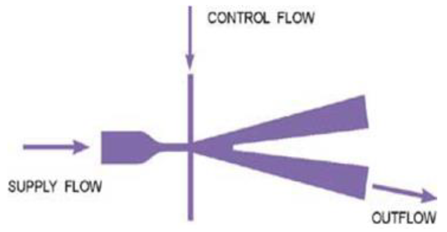
Figure 2.
Geometrical form and meshing prototype.
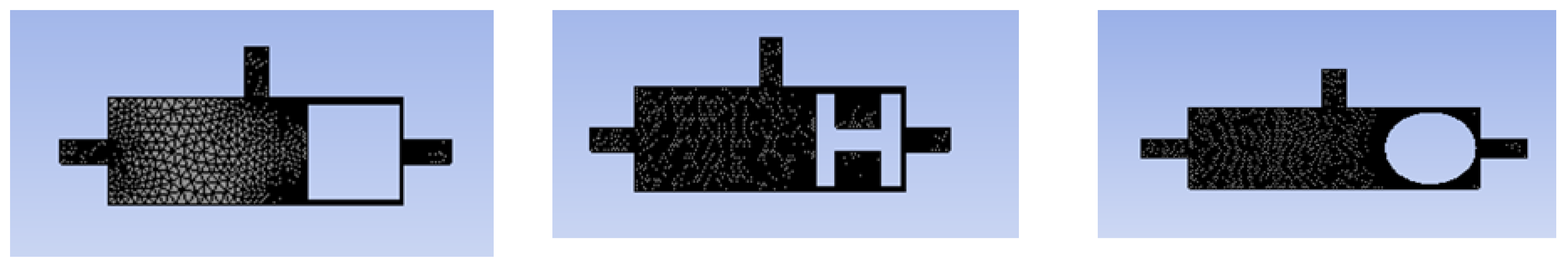
Figure 3.
The geometry representing the combination of the actuator and the oscillator.
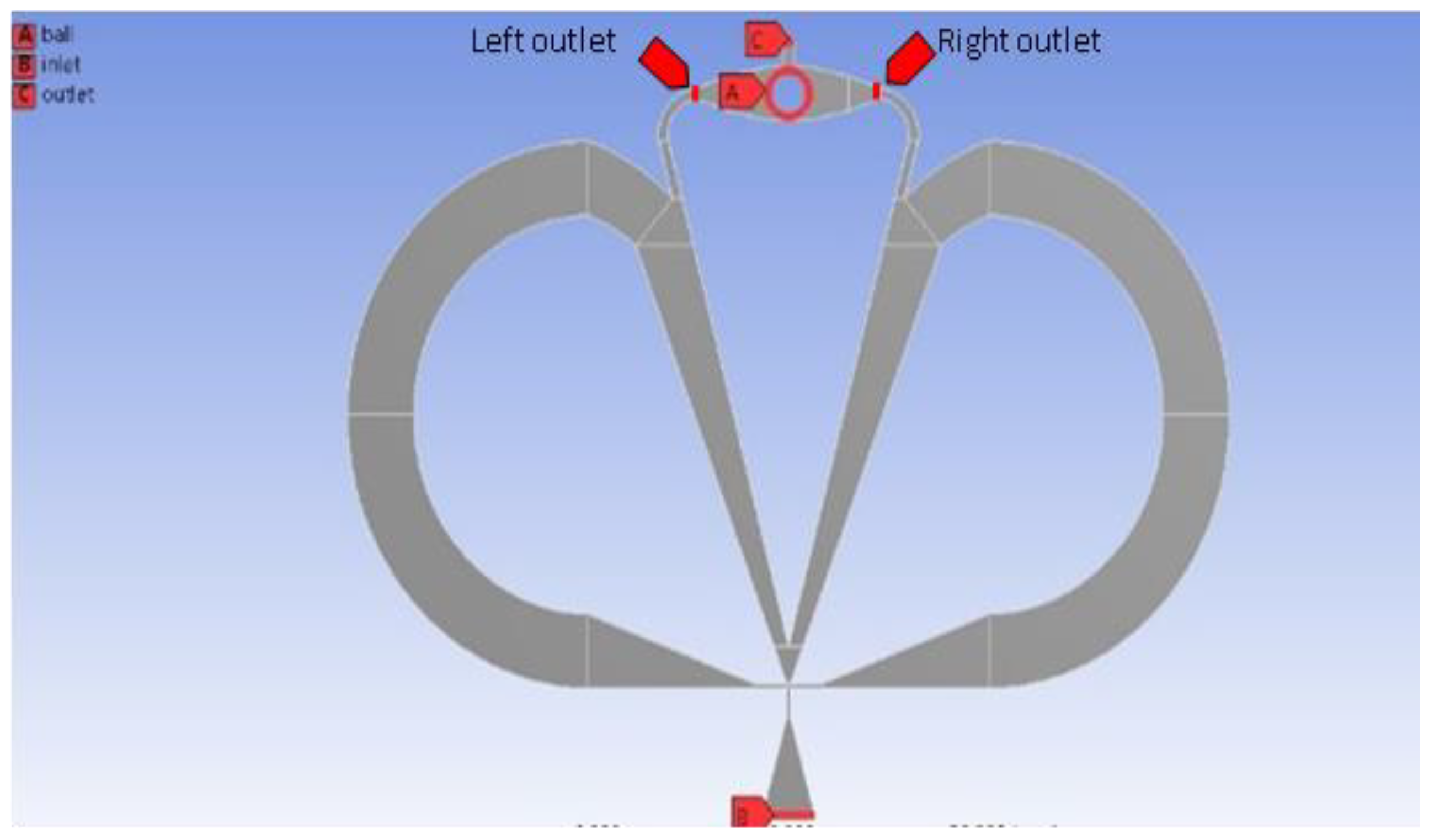
Figure 4.
The mesh used for the simulations of geometry in Fluent.
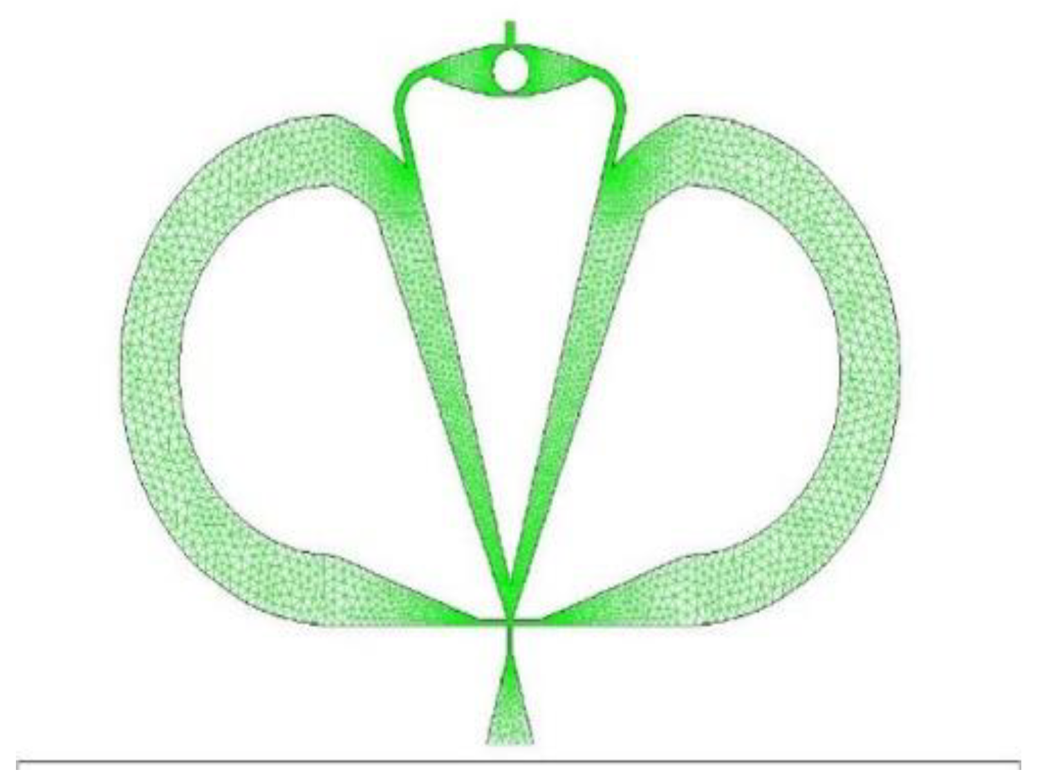
Figure 5.
Mass flow rate signal as a function of time (s) at the output and for a ΔP = 3 bar at the output of the actuator for the circular-shaped mobile.
Figure 5.
Mass flow rate signal as a function of time (s) at the output and for a ΔP = 3 bar at the output of the actuator for the circular-shaped mobile.
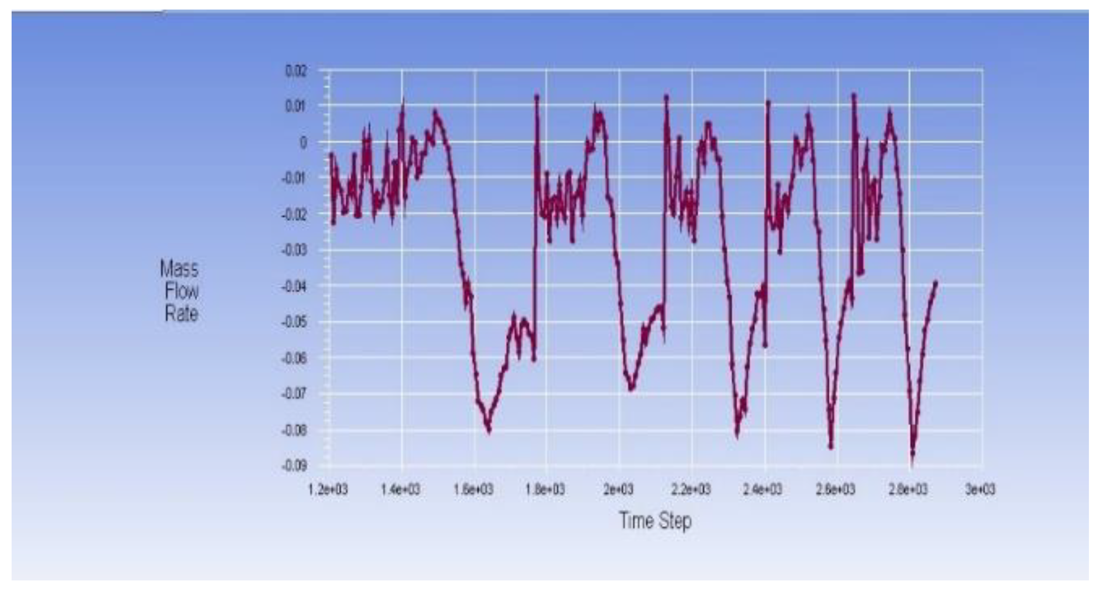
Figure 6.
Contour plots of the velocity Position of the ball at different times.
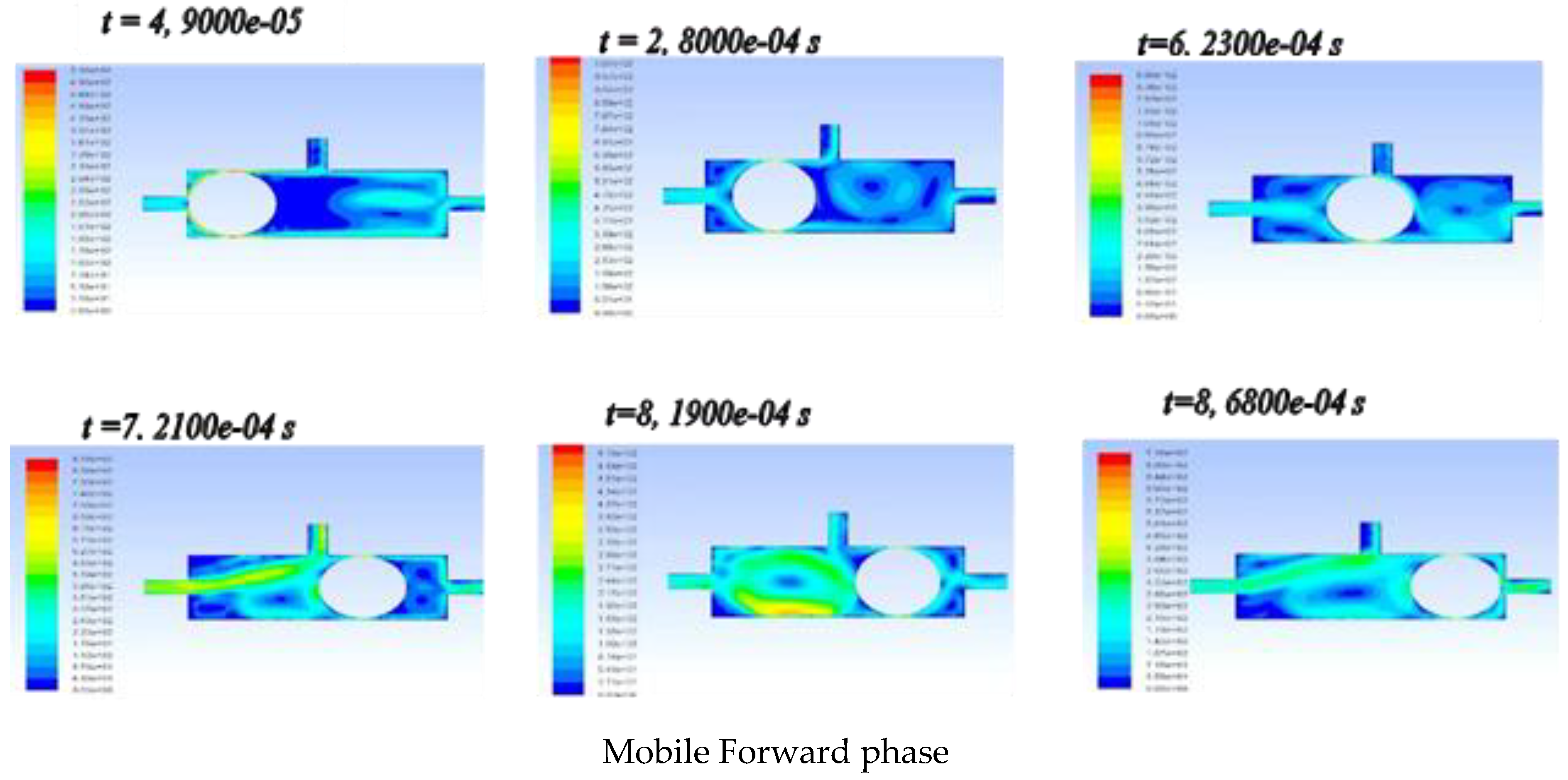
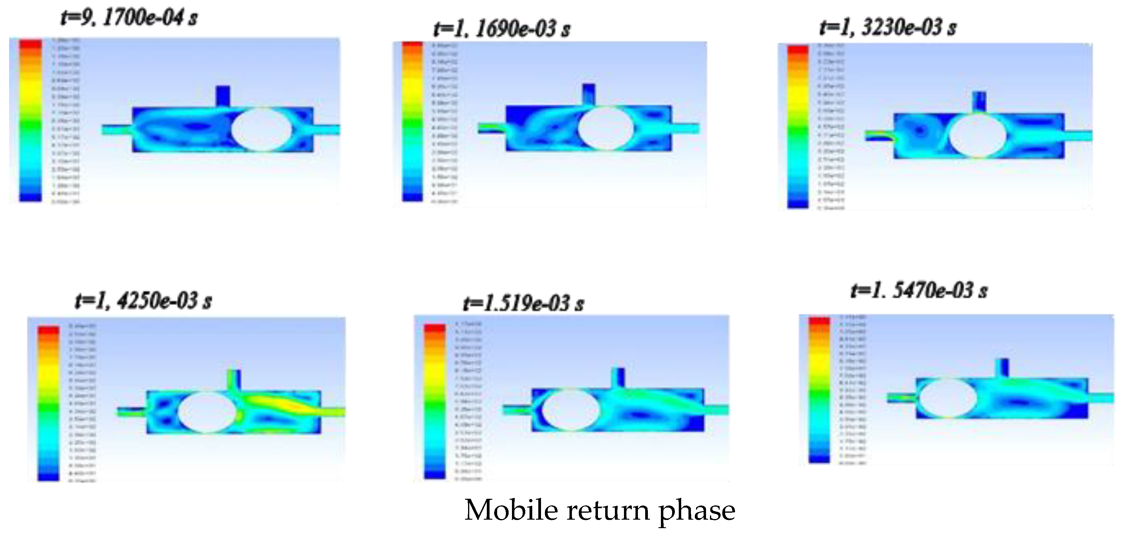
Figure 7.
Mass Flow Rate Signal as a Function of Time at the Right and Left Outlets for the Oscillator-Actuator Combination Subjected to Pressures of 2 Bars and 2.5 Bars.
Figure 7.
Mass Flow Rate Signal as a Function of Time at the Right and Left Outlets for the Oscillator-Actuator Combination Subjected to Pressures of 2 Bars and 2.5 Bars.
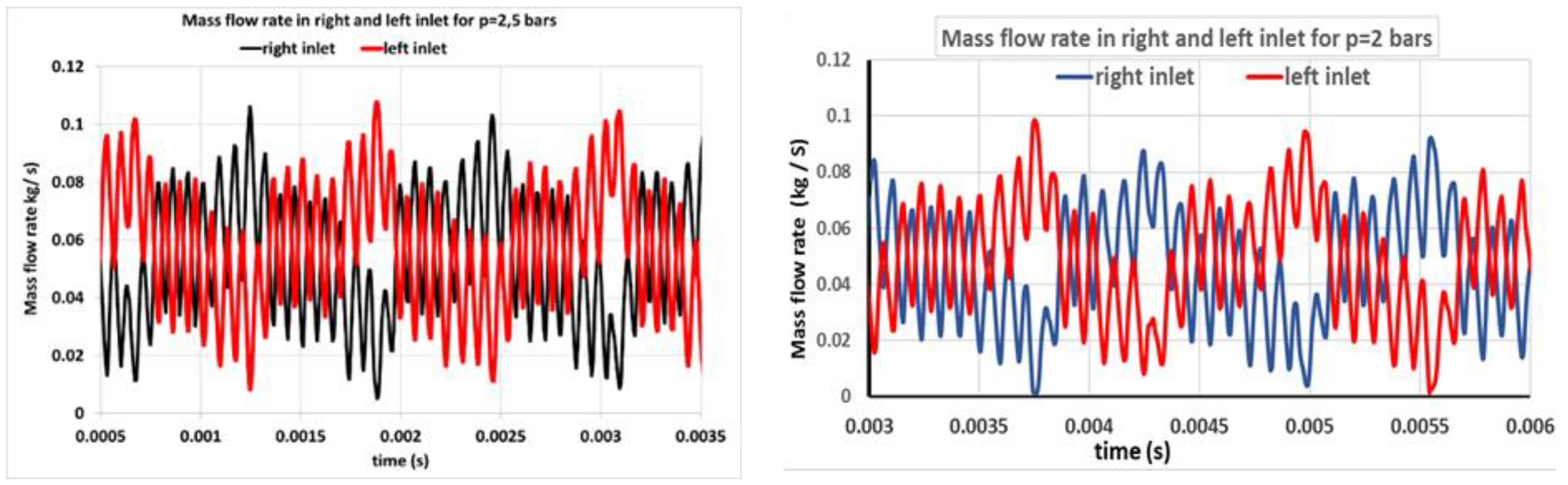
Figure 8.
Axial Velocity Profile as a Function of Time for Pressures P=1.5 barP = 1.5 \, \text{bar}.
Figure 9.
Trend Curve Representing the Oscillation Frequency as a Function of the (ΔP/P).
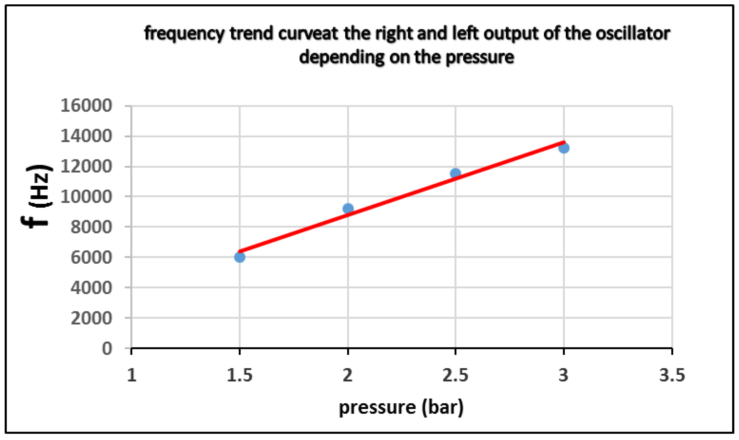

Table 1.
Relevant work on micro actuators.
| reference | First Author | Year | Actuation Type |
Size L*w*h (in µm) |
Operating Conditions |
|---|---|---|---|---|---|
| [36] | Chi S.P. | 1997 | Electro thermal | 1000*700*3 | 15V 2,8µN |
| [37] | Neils T. | 1998 | Electrostatic | 200*100*0,5 | 40V |
| [38] | Just E. | 1999 | SMA | 2000*3900*100 | 22mW 17mN |
| [39] | Bhailis D. | 2000 | Electromagnetic | 5000*5000*2000 | 1A 15mN |
| [05] | Volland B.E. | 2001 | Electrostatic | 3300*1250*5 | 80V 170µm Ø |
| [40] | Fuller, S.B. | 2002 | Electro thermal | / | 300 °C 5V |
| [41] | Abadie J. | 2002 | SMA | 3000*800*200 | 0,8A 68° |
| [25] | Bordatchev E.V. | 2003 | Electro thermal | 2800*1400*12,5 | 1,9V |
| [42] | Olivier. M | 2004 | Electrostatic | 1200*800*10 | 75V |
| [43] | Yang J. | 2004 | Piezoelectric | 1200*320*1,5 | 15V 16,67kHz |
| [44] | Vitorio. A | 2004 | Electrostatic | / | 400V |
| [33] | Zhang H. | 2004 | SMA | 4000*3000*290 | 1A 81µm Ø |
| [45] | Ahn | 2004 | Electromagnetic | 3500*3500 | 20mA 920Hz |
| [46] | Fu | 2004 | SMA | 2200*2200 | 5V 30mA |
| [02] | D.Piyabongkarn | 2005 | Electrostatic | 3200*3000*50 | 10V |
| [29] | C.T. Pan | 2005 | Electromagnetic | 1000*1000*10 | 5V 17,5° |
| [31] | D.H. Kim | 2005 | Electromagnetic | 15500*5220*500 | 8V 18mN |
| [47] | Mitsui | 2006 | Electromagnetic | 7400*9800 | 4.6mA 80,5Hz |
| [13] | S.K.Nah | 2007 | Piezoelectric | 36000*30000*3 | 0-100V |
| [06] | Felix. B | 2007 | Electrostatic | 7700*5600*50 | 150V 100µm Ø |
| [48] | Liu X. | 2007 | Electrostatic | 4000*4000 | 30V |
| [49] | Young-ho C. | 2007 | Electromagnetic | 4000*4000*570 | 27mA 11kHz |
| [50] | Andrew C. | 2007 | Electromagnetic | 200*2*3.5 | 4V 200µN |
| [51] | Kim | 2007 | Electromagnetic | 2400*2900 | 3V 350Hz |
| [52] | Vagia. M | 2008 | Electrostatic | 400*400 | / |
| [07] | Chen. T | 2008 | Electrostatic | 6200*3500*50 | 30V 150µm Ø |
| [53] | Gustavo.A. | 2008 | Electro thermal | 500*500*30 1000*1000*30 |
70mW 79mW |
| [54] | Guo S. | 2008 | SMA | 45000*30000*30000 | 1000µL 50 Hz |
| [55] | P. M. Nieva | 2008 | Electro thermal | 200*25*2 | 10V 3.7-13.3µm |
| [08] | Varona. J | 2009 | Electrostatic | 100*100*3,5 | 45V |
| [56] | Jia | 2009 | Electro thermal | 1000*1000 | 8V 336Hz |
| [57] | Micky.R. | 2010 | Piezoelectric | 15000*2000*300 | 100V 15mN |
| [58] | Zhu | 2011 | Piezoelectric | 2000*2000 | 2V 316Hz |
| [16] | Koh | 2011 | Piezoelectric | 5000*5000 | 9V 30Hz |
| [59] | Lan C.C. | 2011 | SMA | 45000*70000*20500 | 3.6 V 490mN |
| [60] | Liu | 2012 | Electro thermal | 2000*2000 | 0,6V 197Hz |
| [09] | Jia. Y | 2013 | Electrostatic | 6900*6500*50 | 120V |
| [61] | Q. Xu | 2013 | Piezoelectric | 26000*5000*860 | 2V 500Hz |
| [62] | Park, E.S. | 2013 | Electrostatic | 650*90*2.25 | 200°C 10Ω |
| [63] | Ren-Jung Chang | 2013 | SMA | 937*477 | 50mA 3V |
| [64] | Bessonov, A. | 2014 | Piezoelectric | 25000*1000*6.6 | / |
| [65] | A. Sharma | 2015 | Piezoelectric | 7100*2300*566 | 114Hz 54nW |
| [66] | Salem Saadon | 2015 | Piezoelectric | 2450*780*512 | 0,4V 6,8µW |
| [67] | Hussein hussein | 2015 | Electro thermal | 3200*400*100 | 15V 18V |
| [68] | Marija Cauchi | 2016 | Electro thermal | 411*45*4 | 0,22V 9µm Ø |
| [69] | Bruno Andò | 2016 | Electromagnetic | 95000*20000*140 | 4.1 Hz 37.1 mT |
| [70] | Yuki Yamamoto | 2016 | Electrostatic | 10000*10000*38 | 38mg |
| [71] | Haijun Zhang | 2017 | Electro thermal | 580*105 | 13.7 µm 2 Hz |
| [72] | Achraf Kachroudi | 2017 | Piezoelectric | 20000*20000*150 | d33=750 at 25°C |
| [73] | Yingxiang Liu | 2018 | Piezoelectric | 80800*48000*24000 | 427 mm/s |
| [27] | Marija Cauchi | 2018 | Electro thermal | 606*169*28 | 3V (5-9)µm |
| [74] | Ying Wu | 2019 | Piezoelectric | 12000*10000*8000 | 5.86 x 10⁵ µrad/s |
| [28] | Rolend Elsen | 2019 | Electro thermal | / | 1V (55-110) µm |
| [75] | Palak Bhushan | 2020 | Electromagnetic Actuator | 4cm and weighs 133 mil-gr | voltage (<3 V) |
| [76] | Fan, J. | 2020 | Pneumatic actuator | 175000 × 100000 × 60000 | 0.01 to 0.09 |
| [77] | Nader A. Mansour | 2021 | Electromagnetic Actuator | 15000 × 15000 × 40 000 | 0 to 100 mA |
| [78] | Cheng, P. | 2021 | Vacuum buckling | 220000 | −0.002 to −0.1 MPA 0.6 to 2 HZ |
| [79] | Saurabh .Jadhav | 2023 | Pneumatic actuators | 60000 x60000 |
Disclaimer/Publisher’s Note: The statements, opinions and data contained in all publications are solely those of the individual author(s) and contributor(s) and not of MDPI and/or the editor(s). MDPI and/or the editor(s) disclaim responsibility for any injury to people or property resulting from any ideas, methods, instructions or products referred to in the content. |
© 2025 by the authors. Licensee MDPI, Basel, Switzerland. This article is an open access article distributed under the terms and conditions of the Creative Commons Attribution (CC BY) license (http://creativecommons.org/licenses/by/4.0/).
Copyright: This open access article is published under a Creative Commons CC BY 4.0 license, which permit the free download, distribution, and reuse, provided that the author and preprint are cited in any reuse.


