
Submitted:
17 January 2025
Posted:
17 January 2025
You are already at the latest version
Abstract
Background/Objectives: Stress concentration around distal screw-removal holes confers a major risk for periprosthetic fractures following conversion total hip arthroplasty (cTHA) for intertrochanteric femoral fractures. Optimal stem-selection criteria and guidelines for cTHA can improve clinical outcomes. We determined the influence of cementless stem length on stress distribution around distal screw-removal holes. Methods: For finite element analysis, institutional data from preoperative CT scans of contralateral femurs of patients who underwent THA were used. To replicate the post-nail-removal state, we used 3D registration of Standard Triangulated Language data of the intramedullary nail as an unused material to simulate distal screw-removal holes, located 135 mm from the proximal end of the intramedullary nail. Cementless stems of 130, 140, 150, and 160 mm were individually registered using STL data, and cTHA models were constructed accordingly. Using simulations under load conditions representing normal walking and stair climbing, the mean and maximum equivalent stress values around the distal screw-removal holes were calculated. Repeated-measures ANOVA with Bonferroni correction was used for multiple comparisons. Results: Compared to the 130-mm stem, the 150-mm and 160-mm stems similarly reduced the maximum equivalent stress around distal screw-removal holes, although the 140-mm stem showed no significant difference with other stems. Conclusions: A ≥150-mm stem length reliably mitigates stress concentration around distal screw-removal holes post-cTHA, is the optimal choice for balancing effectiveness and risk of complications, and may contribute to improved long-term clinical outcomes. This study provides practical evidence for stem selection in cTHA and offers valuable insights for future treatment guidelines.
Keywords:
conversion total hip arthroplasty (cTHA)
; finite element analysis (FEA)
; stress concentration
; periprosthetic fracture
; stem length
1. Introduction
Among older adults, intertrochanteric femoral fractures are common, and unstable types are frequently treated surgically using intramedullary nails [1,2]. However, patient-related factors, such as bone fragility, as well as surgical factors, including insufficient reduction or improper implant positioning, may lead to complications, such as femoral head cut-out, cut-through, nonunion, or pseudoarthrosis. Furthermore, conditions such as femoral head necrosis or osteoarthritis may necessitate salvage surgery, including conversion total hip arthroplasty (cTHA) [3,4,5,6].
Compared to primary total hip arthroplasty (pTHA), cTHA involves greater complexity, is associated with higher perioperative complication rates, and generally yields inferior clinical outcomes [7,8,9,10,11,12]. For both cTHA and pTHA, periprosthetic fractures are among the most common perioperative complications, second only to dislocation [13,14,15,16]. Periprosthetic fractures not only significantly impact patients' activities of daily living and quality of life but also constitute the most expensive perioperative complication, with an approximate cost of $4,000 per case [17]. In Japan, with the increasing proportion of the older population, it is estimated that the incidence of intertrochanteric fractures and the consequent need for cTHA would increases. Therefore, the prevention and management of complications constitutes a critical challenge for orthopedic surgeons.
Among cTHA-associated periprosthetic fractures, stress concentration following stem insertion may cause fractures around distal screw-removal holes [8,18,19,20,21,22]. These fractures frequently occur with minor trauma or without a clear injury mechanism [11,23]. Despite nume
rous studies on stem selection in cTHA, no significant difference in clinical outcomes, including perioperative complications, have been demonstrated, and therefore, stem selection remains largely dependent on the surgeon’s experience and preference [24,25,26,27,28,29,30,31,32,33]. Although cemented stems are sometimes selected to address bone fragility, their use requires considerable expertise, including troubleshooting. Furthermore, the presence of multiple cortical defects or bone voids from prior surgery may hamper adequate cement pressurization, which generates concerns regarding the bone cement implantation syndrome. Thus, a considerable proportion of orthopedic surgeons prefer to use cementless stems [25,26,27].
The stem tip of standard stems frequently aligns near the distal screw-removal hole, which potentially exacerbates stress concentration and increases the risk of periprosthetic fractures. Consequently, revision long stems are frequently selected [25,26,27,28,29,34,35], and their selection is supported by biomechanical studies which suggest that, to ensure stability and stress distribution, fractures and large cortical bone defects should be bridged by implants that extend across at least twice the femoral diameter (approximately 40 mm) [36,37,38].
Nonetheless, it is unclear whether small cortical bone defects, such as distal screw-removal holes, significantly weaken the femoral diaphysis under lower-limb loading. Haidukewych et al. recommended intraoperative filling of cortical bone defects caused by prior screws whenever feasible, as these defects may compromise cement pressurization for cemented stems or constitute stress-concentration sites for cementless stems, and thereby increase the risk of femoral fractures [14]. However, if screw-removal holes are indeed a source of weakness, then the necessary bridging length remains undefined, and the impact of stem length on stress distribution around these holes is unclear.
In our previous study [39], we used Standard Triangulated Language (STL) data for three types of cementless stems—120 mm (0-mm bridging length relative to the distal screw-removal hole), 130 mm (10-mm bridging), and 160 mm (40-mm bridging)—to compare and evaluate stress distribution using finite element analysis (FEA). Compared to the insertion of 120-mm and 130-mm stems, the insertion of a 160-mm stem, which was designed as a revision long stem, significantly reduced the maximum stress on the distal screw-removal hole. Therefore, we concluded that to reliably avoid stress concentration at the distal screw-removal hole when employing a cementless stem in clinical practice, a revision long stem is beneficial. However, the previous study did not clarify whether the 160-mm stem represents the minimum necessary length to avoid stress concentration at the distal screw-removal hole, or elucidate if longer stems might be excessive. Additionally, compared to standard stems, the use of long stems in cTHA is associated with significantly longer surgical times, increased blood loss, and higher rates of intraoperative fractures [40]. Thus, if similar effects can be achieved with shorter stems, then this could potentially reduce perioperative risks.
The present study aimed to investigate the influence of cementless stem length on stress distribution around distal screw-removal holes in greater detail and identify the minimum required length of cementless stems. We believe that refining the selection of optimal stems for cTHA will mitigate the risks of intraoperative and perioperative complications.
To further investigate the optimal stem length for cTHA, we extended our previous study [39] by incorporating two additional stem lengths: 140 and 150 mm (bridging length: 20 and 30 mm, respectively). Using FEA simulations, we analyzed the maximum stress around the distal screw-removal hole and performed statistical evaluations to identify the necessary and sufficient stem length for cTHA.
Based on prior biomechanical studies [36,37,38] and our previous findings [39], we hypothesized that, to significantly reduce maximal stress around the distal screw-removal hole, the optimal stem length would lie between 130 and 160 mm. Considering the lower axial stability demands for smaller defects than for fractures or large cortical voids, we speculated that the sufficient bridging length would be less than 40 mm. This study used FEA to elucidate the optimal length of cementless stems in cTHA following intertrochanteric fractures.
2. Materials and Methods
2.1. Study Setting and Design
This analytical observational study utilized computed tomography (CT) data obtained at a single institution from October 2021 to September 2024. Participants provided informed consent for the use and publication of these data. This analytical observational study was approved by the Ethics Committee of the University of Tsukuba Hospital (approval code: H27-041). We used FEA to determine the optimal length of cementless stems for cTHA following intertrochanteric femoral fractures. Simulations were conducted using pre-existing patient CT data and Standard Triangulated Language (STL) data of femoral stems to analyze femoral stress distribution. This expanded study builds upon our earlier work that was aimed at identifying the optimal stem length for cTHA following intertrochanteric femoral fractures.
2.2. Study Samples
The required sample size was calculated using G*Power (version 3.1.9.7, University of Düsseldorf, Germany). Assuming an effect size of 0.25, a significance level of 0.05, a statistical power of 0.8, and four groups, the minimum sample size was determined as 24. Based on this calculation, we utilized the same 30 femoral CT datasets that were utilized in our previous study.
From among 231 patients who underwent pTHA at our institution between October 2021 and September 2024, we identified 132 female patients aged ≤75 years with Dorr type B [41] femoral morphology. Of these, 11 patients with a history of femoral surgery and 21 with significant deformities, such as Perthes-like deformities, were excluded. From the remaining 100 eligible cases, 30 cases were randomly selected using a simple random sampling method, and CT data from the contralateral femur of these patients were used for analysis (Figure 1).
2.3. Finite Element Analysis
2.3.1. Software and Modeling
We performed FEA using MECHANICAL FINDER (MF, version 13.0, Extended Edition, Research Center of Computational Mechanics, Tokyo, Japan). First, 3D femoral models were generated by importing the contralateral femoral CT data into MF. Next, to replicate the femur after hardware removal, STL data of a Trochanteric Fixation Nail Advanced Proximal Femoral Nailing System (TFNA, Depuy Synthes, Raynham, MA, USA; φ10 mm × 200 mm/130°) were registered and replaced with voids by setting the material property to "unused material. The distal screw has a diameter of 5 mm and, in static fixation, is designed to be positioned 135 mm from the proximal end of the intramedullary nail. The intramedullary nail was inserted into the 3D femur model with the Tip Apex Distance set to less than 20 mm. This model was referred to as the “extraction model.”
Subsequently, STL data of the Universia stem (#11, high offset; Teijin Nakashima Medical, Okayama, Japan) [42] were inserted into the extraction model to create a cTHA model (Figure 2). Neck osteotomy and stem positioning were planned using ZedHip (version 17.0.0, Lexi Co., Ltd., Tokyo, Japan) and faithfully reproduced in MF (Figure 3). Four stem lengths were defined (Figure 2): (1) 130 mm (bridge length: 10 mm), (2) 140 mm (20 mm), (3) 150 mm (30 mm), and (4) 160 mm (40 mm). Among these, only the 130-mm stem is clinically available; the other lengths were virtual stems designed by editing STL data for simulation purposes.
2.3.2. Material Parameters
Tetrahedral elements with four nodes were used as solid elements. A shell element of 0.001-mm thickness was applied to the bone surface because it does not affect structural strength. Mesh sizes were determined based on a mesh convergence test from our previous study; accordingly, we selected a size of 1–2 mm to balance computational efficiency and accuracy.
Bone material properties were modeled as inhomogeneous, and the Young's modulus was derived from bone mineral density (BMD) calculated from Hounsfield Unit (HU) values, based on a linear relationship [43,44]. Keyak's predictive conversion formula was applied for estimation [45]. The Poisson ratio was set to 0.40. The titanium alloy (Ti-6Al-4V) used for the stem was modeled as a homogeneous material with Young's modulus of 109 GPa and Poisson ratio of 0.28 (Table 1) [43,45].
2.3.3. Loading and Boundary Conditions
Simulations were performed under maximum loading conditions during "normal walking" and "stair climbing," as reported in previous studies [46,47]. The load vectors, magnitude, and directions were determined based on patient body weight (Table 2, Figure 4). The distal femur was fully constrained, and a friction coefficient of 0.49 was applied to the contact surface between the femur and stem [48].
2.3.4. Static Structural Analysis
Linear static analysis was performed with gradually increasing loads.
2.4. Data Collection and Candidate Predictors
Patient demographic data, including age, height, weight, body mass index (BMI), femoral neck BMD, and the Canal Flare Index (CFI) [49], were retrospectively collected from medical records. Preoperative measurements were used for age, height, weight, and BMI, while BMD was assessed using Hologic Discovery A (Hologic Inc., Bedford, MA, USA). Parameters such as stem anteversion angle, bridge length, and distal screw length were measured on the constructed cTHA models.
The stem-anteversion angle was defined as the angle between the stem neck and the posterior condylar axis. Measurements were conducted three times under identical conditions by the same investigator(K.S), and the mean values were used to minimize variability and enhance reliability. Data were uniformly expressed as mean ± standard deviation (SD).
2.5. Outcomes
Simulations were performed under "normal walking" and "stair climbing" conditions for stems of 130-, 140-, 150-, and 160-mm length. The mean and maximum equivalent stress values on the inner and outer surfaces around the distal screw-removal hole were calculated. The analysis focused on shell elements within a 10-mm radius sphere centered on the distal screw-removal hole (Figure 5). Data were reported as mean values with 95% confidence interval (95% CI).
2.6. Statistical Analysis
Statistical analysis was conducted using SPSS Statistics (version 29.0.2.0, IBM Corp., Armonk, NY, USA). Normality was assessed with the Shapiro–Wilk test. A significance level of α = 0.05 was adopted. If data were normally distributed (p > 0.05), parametric tests were applied for intergroup comparisons.
3. Results
The characteristics of the participants and the 3D-cTHA model constructed in this study are summarized in Table 3.
Data are presented as mean ± SD.
The maximum equivalent stress at the medial and lateral regions of distal screw removal holes for the four groups (130, 140, 150, and 160 mm) under both "normal walking" and "stair climbing" conditions followed a normal distribution. The results of the Shapiro–Wilk test were as follows:
- Normal walking - medial: 130 mm: W = 0.947, p = 0.140; 140 mm: W = 0.975, p = 0.680; 150 mm: W = 0.956, p = 0.246; 160 mm: W = 0.980, p = 0.830
- Normal walking - lateral: 130 mm: W = 0.975, p = 0.690; 140 mm: W = 0.974, p = 0.639; 150 mm: W = 0.981, p = 0.852; 160 mm: W = 0.967, p = 0.465
- Stair climbing - medial: 130 mm: W = 0.973, p = 0.612; 140 mm: W = 0.964, p = 0.394; 150 mm: W = 0.969, p = 0.505; 160 mm: W = 0.970, p = 0.548
Stair climbing - lateral: 130 mm: W = 0.957, p = 0.259; 140 mm: W = 0.980, p = 0.825; 150 mm: W = 0.972, p = 0.586; 160 mm: W = 0.981, p = 0.844 (Figure 6).
Given these results, repeated-measures analysis of variance (ANOVA) was selected for comparison of the four groups using paired data. Post hoc multiple comparisons were performed with Bonferroni correction to assess differences between all group combinations.
3.1. Mean Equivalent Stress Around Distal Screw-removal Holes
Scatterplots of mean equivalent stress at the distal screw removal holes and their trendlines are shown in Figure 7. Under both "normal walking" and "stair climbing" conditions, the mean equivalent stress decreased as the stem length increased.
3.2. Maximum Equivalent Stress Around Distal Screw-Removal Holes
3.2.1. Normal Walking Condition
3.2.1.1. Comparison Across the Four Groups
Significant main effects were observed in the ANOVA for both the medial (F(3, 87) = 6.263, p < 0.001, η² = 0.18) and lateral sides (F(3, 87) = 7.752, p < 0.001, η² = 0.21; Table 4).
3.2.1.2. Post Hoc Multiple Comparisons
Compared to the 130-mm group, significant intergroup differences were found with 150-mm and 160-mm groups on both the medial and lateral sides (130 mm vs. 150 mm: medial, p = 0.035; lateral, p = 0.006; 130 mm vs. 160 mm: medial, p = 0.006; lateral, p = 0.007). On the medial side, the stress values for the 150-mm and 160-mm groups were lower by an average of 6.300 MPa (95% CI: −12.283, −0.317) and 6.395 MPa (95% CI: −11.333, −1.457), respectively, compared to the 130-mm group. On the lateral side, the stress values for the 150-mm and 160-mm groups were lower by an average of 5.190 MPa (95% CI: −9.223, −1.157) and 5.600 MPa (95% CI: −9.989, −1.211), respectively.
No significant differences were observed between the 140-mm group and any other group (140 mm vs. 130 mm: medial, p > 0.99; lateral, p = 0.210; vs. 150 mm: medial, p = 0.155; lateral, p = 0.384; vs. 160 mm: medial, p = 0.119; lateral, p = 0.191), or between the 150-mm and 160-mm groups (medial, p > 0.99; lateral, p > 0.99) (Figure 8).
3.2.2. Stair Climbing Condition
3.2.2.1. Comparison Across the Four Groups
Significant main effects (Table 4) were observed in the ANOVA for both the medial (F(3, 87) = 3.495, p = 0.019, η² = 0.11) and lateral sides (F(3, 87) = 4.822, p = 0.004, η² = 0.14).
3.2.2.2. Post Hoc Multiple Comparisons
Significant differences were found between the 130-mm group and both the 150-mm and 160-mm groups on both the medial and lateral sides (130 mm vs. 150 mm: medial, p = 0.036; lateral, p = 0.010; 130 mm vs. 160 mm: medial, p = 0.007; lateral, p = 0.019). On the medial side, the stress values for the 150-mm and 160-mm groups were lower by an average of 8.430 MPa (95% CI: −16.474, −0.386) and 8.870 MPa (95% CI: −15.870, −1.870), respectively, compared to the 130-mm group. On the lateral side, the stress values for the 150-mm and 160-mm groups were lower by an average of 5.350 MPa (95% CI: −9.710, −0.990) and 5.557 MPa (95% CI: −10.435, −0.678), respectively.
No significant differences were observed between the 140 mm group and any other group (140 mm vs. 130 mm: medial and lateral, p > 0.99; vs. 150 mm: medial, p = 0.488; lateral, p = 0.393; vs. 160 mm: medial, p = 0.548; lateral, p = 0.433), nor between the 150 mm and 160 mm groups (medial and lateral, p > 0.99) (Figure 8).
4. Discussion
We conducted an expanded study by utilizing FEA to investigate the optimal stem length for cTHA following intertrochanteric femoral fractures. This study builds on the methodology and design of a previous study [39]. The average equivalent stress at the distal screw-removal holes gradually decreased with increasing stem length on both medial and lateral sides. The maximum equivalent stress values were as follows:
Compared to the 130-mm stem, the 150-mm and 160-mm stems were associated with significantly lower stress.
There was no significant difference between the 150-mm and 160-mm stems in stress reduction.
The 140-mm stem showed no significant difference compared to any other stem length.
For fractures and large bone defects, it is generally recommended to bridge gaps with implants, such as stems or intramedullary nails, that have at least twice the bone diameter (approximately 40 mm) [36,37,38]. Moreover, this principle underpins the treatment strategies for other conditions that require stem bridging, such as Vancouver type B2 or B3 fractures.
Despite the lack of an established consensus regarding the management of relatively small cortical defects, such as screw-removal holes, some reports related to the management of cTHA have been published. Unlike intramedullary nails, reports on extramedullary fixation devices, such as nail plates, suggest that fractures were not induced despite no extended stem bridging over the screw-removal holes [50]. Postmortem studies have demonstrated that bridging lengths of 1.5 times the femoral diameter minimized stress at screw-removal holes [51].
Biomechanical studies on bone hole strength have been reported. Studies using animal bones revealed that drill holes of 3–4 mm diameter or cortical defects exceeding 20% of the bone diameter significantly reduced the energy-absorption capacity, although torsional strength was not greatly affected [52,53,54,55].
In this study, the distal screw-removal holes correspond to approximately 20% bicortical defects, as the distal screw diameter was 5 mm and the femoral diameter was 25.7±1.7 mm. Thus, these areas may be structurally vulnerable during load transmission. To avoid stress concentration and prevent fractures at distal screw-removal holes, it is recommended that a stem of sufficient length is used for cTHA.
Our expanded study revealed that 150-mm (bridging length: 30 mm) or 160-mm (bridging length: 40 mm) stems are desirable to reduce stress at distal screw-removal holes. Although stems longer than 160 mm might provide greater stress distribution, this remains unclear. Furthermore, longer stems are associated with increased operative time, intraoperative bleeding, and perioperative complications [43]. Considering that it achieves similar stress distribution as the 160-mm stem, the 150-mm stem is the preferred option.
The 140-mm stem represents a middle-ground approach. Although shorter stems preserve bone stock and promote physiological stress distribution, they may increase stress on weak bone, and thereby confer a higher risk of peri-stem fractures in osteoporotic patients. Conversely, longer stems reduce localized stress concentration but may cause proximal stress shielding, and accordingly lead to proximal femoral bone resorption [56,57,58]. In clinical practice, especially among Japanese individuals with a smaller build and curved femoral shapes, achieving sufficient stem length may not always be feasible. A 140-mm stem, therefore, could offer a balanced solution for minimizing perioperative complication risks and maintaining adequate strength by avoiding the use of excessively long stems that might be incompatible with the patient’s femoral anatomy or bone fragility. Depending on the case, this trade-off might represent a well-balanced and viable option for improved clinical outcomes. Depending on the type of intramedullary nail used in the initial surgery, the position of the distal screw-removal hole can vary slightly. In the comparison of the distal screw-removal hole positions under static fixation for the major intramedullary nails that are currently used for intertrochanteric femoral fractures, the TFNA (Depuy Synthes, Raynham, MA, USA) and InterTAN (Smith & Nephew, Memphis, TN, USA) both had distal screw-removal holes located 135 mm from the proximal end of the intramedullary nail. In contrast, for the Gamma 3 nail (Stryker, Mahwah, New Jersey, USA), the distal screw-removal hole is positioned at 140 mm from the proximal end of the intramedullary nail. Consequently, the stem length required to ensure sufficient bridging length in cTHA is expected to be longer, and this warrants careful consideration.
In any case, when selecting from the stem lengths available for clinical use, cementless stems inevitably require the use of revision long stems, leaving limited options. Moving forward, it is hoped that the development of stems of more appropriate lengths tailored to individual patients, from the perspective of stress distribution, will provide orthopedic surgeons with greater flexibility in their choices.
Structurally weak regions, such as screw-removal holes, are prone to stress concentration, and increase the fracture risk. When stems of insufficient length are used, the placement of the stem tip near the screw-removal holes may amplify stress concentration through a hinge effect.
In general, inserting a stem with greater rigidity than the femur facilitates broader stress distribution via the stem. Longer stems, being more rigid, are likely to distribute stress more effectively and reduce localized stress at screw-removal holes. Furthermore, stems may physically reinforce the structural weakness at screw-removal holes.
Significant fractures or cortical bone defects critically affect bone strength and require robust implant bridging for ensuring axial stability whereas smaller defects, such as screw-removal holes, may have a more limited impact. In cTHA, the primary purpose of bridging is to reinforce strength and stiffness in response to cortical bone deficiencies and thereby reduce stress. It is presumed that the necessary and sufficient bridging length may be shorter as compared to the length required for fractures or significant cortical bone defects. In this study, we found that a stem length of 150 mm was the sufficient length required to avoid stress concentration at the distal screw-removal hole, and corresponds to a bridging length of 30 mm, or 1.2 times the femoral diameter.
The number of patients with intertrochanteric fractures is expected to increase with population aging and could thereby increase the demand for cTHA; this highlights the importance of strategies to address postoperative complications. Among these, periprosthetic fractures—particularly around distal screw-removal holes—represent significant complications, with surgical factors, such as stress concentration, playing a potential role.
Despite the empirical use of long stems by many orthopedic surgeons, no prior study has rigorously examined the relationship between stem length and stress distribution around screw-removal holes. A previous study [39] demonstrated via FEA that long stems significantly reduced maximum stress at distal screw-removal holes. The present expanded study further examined stem lengths in greater detail, by employing repeated measurements to reduce data variability and improve statistical power, to thereby minimize the required sample size. Although additional simulations and statistical analyses were necessary, compared to strain gauge methods or thermoelastic stress analysis, this study achieved cost and time efficiency. Importantly, FEA enabled detailed analysis of femoral stresses, including those within the screw-removal holes—an area that is inaccessible to analysis using other methods.
The strength of this research is that the results provide new insights into optimal stem length in cTHA and offers valuable data to guide orthopedic surgeons in the selection of appropriate stems.
Nonetheless, the limitations of this study and future perspectives warrant discussion. First, similar to our previous study, this research was conducted under idealized conditions, which do not fully replicate in vivo environments, including bone heterogeneity and dynamic load conditions. Using MF software, we incorporated patient-specific bone microstructures by estimating bone density from CT values. Simulating maximal daily living loads with muscle dynamics aimed to approximate real-world scenarios. Nevertheless, CT scanner settings significantly impact FEA model accuracy by necessitating a balance between resolution and computational efficiency. Second, to simplify the model, this study did not replicate fracture lines, callus formation, or bone sclerosis around intramedullary nails and screw-removal holes. Although these factors could be included using post-nail-removal CT data, such cases are rare, which makes adequate sample collection challenging. We addressed this by replacing nail properties with the "unused material" settings in MF software to simulate post-removal conditions. Third, this study focused solely on stem length, and excluded factors such as stem diameter, shape, and fixation concepts. Although stem size was standardized to #11, variations in patient-specific femoral canal shapes may have influenced the results. Future studies should consider these parameters. Thus, although this study focused on the evaluation of stem length, the evident approach to further investigations would involve the generation of multiple hypothetical stem CAD models while incorporating variations in parameters, such as diameter, shape, and fixation concepts, followed by the validation of each of these models. Alternatively, validations would need to be conducted for each variation of the available stems.
Finally, FEA remains a simulation-based approach that requires experimental validation. Subsequent research should include physical models and clinical trials to complement and verify simulation findings. Moreover, comparative studies with cemented stems in osteoporotic models may be valuable.
5. Conclusions
When performing cTHA with a cementless stem following intramedullary nailing for intertrochanteric femoral fractures, a stem length of at least 150 mm is desirable to avoid stress concentration at the distal screw-removal hole. In this study, a 150-mm stem corresponded to a bridging length of 30 mm, or approximately 1.2 times the femoral diameter. This length is particularly optimal when balancing the minimizing of the risk of complications and maximizing effectiveness, and potentially contributes to improved long-term clinical outcomes. Therefore, in clinical practice, the use of revision long stems is recommended.
Author Contributions
Conceptualization, K.S.; methodology, K.S.; software, K.S. and R.W.; validation, K.S.; formal analysis, K.S.; investigation, K.S., F.H. and S.Y.; resource, K.S., T.Y, R.W., F.H. and S.Y.; data curation, K.S., F.H. and S.Y.; writing-original draft preparation, K.S.; writing-review and editing, T.N., T.Y., R.W. and H.M.; visualization, K.S.; supervision, T.N., T.Y., R.W. and H.M.; project administration, T.N., T.Y., R.W. and H.M. All authors reviewed the results and approved the final version of the manuscript.
Funding
This research received no external funding.
Institutional Review Board Statement
The study was conducted in accordance with the Declaration of Helsinki, and approved by the Ethics Committee of the University of Tsukuba Hospital (protocol code H27-041 and date of approval: August 14, 2022).
Informed Consent Statement
Informed consent was obtained from all subjects involved in the study.
Data Availability Statement
The data is available from the corresponding author if required.
Acknowledgments
The authors would like to thank Editage (http://www.editage.jp/) for their assistance with English language editing and Teijin Nakashima Medical (Okayama, Japan) for providing the STL data of the Universia stem.
Conflicts of Interest
The authors declare no conflicts of interest.
Abbreviations
The following abbreviations are used in this manuscript:
| BMD | Bone mineral density |
| CFI | Canal Flare Index |
| cTHA | Conversion total hip arthroplasty |
| FEA | Finite element analysis |
| pTHA | Primary total hip arthroplasty |
References
- Hip fracture: Management. Available online: https://www.ncbi.nlm.nih.gov/books/NBK553768/ (accessed on Jan.15 2025).
- O’Connor, M.I.; Switzer, J.A. AAOS clinical practice guideline summary: Management of hip fractures in older adults. J Am Acad Orthop Surg 2022, 30, e1291–e1296. [Google Scholar] [CrossRef] [PubMed]
- Geller, J.A.; Saifi, C.; Morrison, T.A.; Macaulay, W. Tip-apex distance of intramedullary devices as a predictor of cut-out failure in the treatment of peritrochanteric elderly hip fractures. Int Orthop 2010, 34, 719–722. [Google Scholar] [CrossRef]
- Mavrogenis, A.F.; Panagopoulos, G.N.; Megaloikonomos, P.D.; Igoumenou, V.G.; Galanopoulos, I.; Vottis, C.T.; Karabinas, P.; Koulouvaris, P.; Kontogeorgakos, V.A.; Vlamis, J.; et al. Complications after hip nailing for fractures. Orthopedics 2016, 39, e108–e116. [Google Scholar] [CrossRef]
- Mokka, J.; Kirjasuo, K.; Koivisto, M.; Virolainen, P.; Junnila, M.; Seppänen, M.; Äärimaa, V.; Isotalo, K.; Mäkelä, K.T. Hip arthroplasty after failed nailing of proximal femoral fractures. Eur Orthop Traumatol 2012, 3, 231–237. [Google Scholar] [CrossRef]
- Murena, L.; Moretti, A.; Meo, F.; Saggioro, E.; Barbati, G.; Ratti, C.; Canton, G. Predictors of cut-out after cephalomedullary nail fixation of pertrochanteric fractures: A retrospective study of 813 patients. Arch Orthop Trauma Surg 2018, 138, 351–359. [Google Scholar] [CrossRef] [PubMed]
- Corró, S.; Óleo-Taltavull, R.; Teixidor-Serra, J.; Tomàs-Hernández, J.; Selga-Marsà, J.; García-Sánchez, Y.; Guerra-Farfán, E.; Andrés-Peiró, J.-V. Salvage hip replacement after cut-out failure of cephalomedullary nail fixation for proximal femur fractures: A case series describing the technique and results. Int Orthop 2022, 46, 2775–2783. [Google Scholar] [CrossRef]
- Archibeck, M.J.; Carothers, J.T.; Tripuraneni, K.R.; White, R.E., Jr. Total hip arthroplasty after failed internal fixation of proximal femoral fractures. J Arthroplasty 2013, 28, 168–171. [Google Scholar] [CrossRef] [PubMed]
- Douglas, S.J.; Remily, E.A.; Sax, O.C.; Pervaiz, S.S.; Delanois, R.E.; Johnson, A.J. How does conversion total hip arthroplasty compare to primary? J Arthroplasty 2021, 36, S155–S159. [Google Scholar] [CrossRef]
- Solarino, G.; Bizzoca, D.; Dramisino, P.; Vicenti, G.; Moretti, L.; Moretti, B.; Piazzolla, A. Total hip arthroplasty following the failure of intertrochanteric nailing: First implant or salvage surgery? World J Orthop 2023, 14, 763–770. [Google Scholar] [CrossRef] [PubMed]
- Gjertsen, J.E.; Lie, S.A.; Fevang, J.M.; Havelin, L.I.; Engesaeter, L.B.; Vinje, T.; Furnes, O. Total hip replacement after femoral neck fractures in elderly patients: Results of 8,577 fractures reported to the Norwegian Arthroplasty Register. Acta Orthop 2007, 78, 491–497. [Google Scholar] [CrossRef] [PubMed]
- Tetsunaga, T.; Fujiwara, K.; Endo, H.; Noda, T.; Tetsunaga, T.; Sato, T.; Shiota, N.; Ozaki, T. Total hip arthroplasty after failed treatment of proximal femur fracture. Arch Orthop Trauma Surg 2017, 137, 417–424. [Google Scholar] [CrossRef] [PubMed]
- Haentjens, P.; Casteleyn, P.P.; Opdecam, P. Hip arthroplasty for failed internal fixation of intertrochanteric and subtrochanteric fractures in the elderly patient. Arch Orthop Trauma Surg 1994, 113, 222–227. [Google Scholar] [CrossRef]
- Haidukewych, G.J.; Berry, D.J. Hip arthroplasty for salvage of failed treatment of intertrochanteric hip fractures. J Bone Joint Surg Am 2003, 85, 899–904. [Google Scholar] [CrossRef] [PubMed]
- Winemaker, M.; Gamble, P.; Petruccelli, D.; Kaspar, S.; de Beer, J. Short-term outcomes of total hip arthroplasty after complications of open reduction internal fixation for hip fracture. J Arthroplasty 2006, 21, 682–688. [Google Scholar] [CrossRef] [PubMed]
- Stoffelen, D.; Haentjens, P.; Reynders, P.; Casteleyn, P.P.; Broos, P.; Opdecam, P. Hip arthroplasty for failed internal fixation of intertrochanteric and subtrochanteric fractures in the elderly patient. Acta Orthop Belg 1994, 60 Suppl 1, 135–139. [Google Scholar]
- Binkley, N.; Nickel, B.; Anderson, P.A. Periprosthetic fractures: An unrecognized osteoporosis crisis. Osteoporos Int 2023, 34, 1055–1064. [Google Scholar] [CrossRef] [PubMed]
- Abdel, M.P.; Watts, C.D.; Houdek, M.T.; Lewallen, D.G.; Berry, D.J. Epidemiology of periprosthetic fracture of the femur in 32 644 primary total hip arthroplasties: A 40-year experience. Bone Joint J 2016, 98–B, 461–467. [Google Scholar] [CrossRef]
- Ashkenazi, I.; Amzallag, N.; Factor, S.; Abadi, M.; Morgan, S.; Gold, A.; Snir, N.; Warschawski, Y. Age as a risk factor for intraoperative periprosthetic femoral fractures in cementless hip hemiarthroplasty for femoral neck fractures: A retrospective analysis. Clin Orthop Surg 2024, 16, 41–48. [Google Scholar] [CrossRef]
- Morice, A.; Ducellier, F.; Bizot, P.; Orthopaedics and Traumatology Society of Western France (SOO). Total hip arthroplasty after failed fixation of a proximal femur fracture: Analysis of 59 cases of intra- and extra-capsular fractures. Orthop Traumatol Surg Res 2018, 104, 681–686. [Google Scholar] [CrossRef]
- Puri, S.; Sculco, P.K.; Abdel, M.P.; Wellman, D.S.; Gausden, E.B. Total hip arthroplasty after proximal femoral nailing: Preoperative preparation and intraoperative surgical techniques. Arthroplast Today 2023, 24, 101243. [Google Scholar] [CrossRef]
- Chen, D.W.; Lin, C.L.; Hu, C.C.; Tsai, M.F.; Lee, M.S. Biomechanical consideration of total hip arthroplasty following failed fixation of femoral intertrochanteric fractures – A finite element analysis. Med Eng Phys 2013, 35, 569–575. [Google Scholar] [CrossRef]
- Beals, R.K.; Tower, S.S. Periprosthetic fractures of the femur. An analysis of 93 fractures. Clin Orthop Relat Res 1996, (327), 238–246. [Google Scholar] [CrossRef]
- DeHaan, A.M.; Groat, T.; Priddy, M.; Ellis, T.J.; Duwelius, P.J.; Friess, D.M.; Mirza, A.J. Salvage hip arthroplasty after failed fixation of proximal femur fractures. J Arthroplasty 2013, 28, 855–859. [Google Scholar] [CrossRef]
- Shi, X.; Zhou, Z.; Yang, J.; Shen, B.; Kang, P.; Pei, F. Total hip arthroplasty using non-modular cementless long-stem distal fixation for salvage of failed internal fixation of intertrochanteric fracture. J Arthroplasty 2015, 30, 1999–2003. [Google Scholar] [CrossRef] [PubMed]
- Thakur, R.R.; Deshmukh, A.J.; Goyal, A.; Ranawat, A.S.; Rasquinha, V.J.; Rodriguez, J.A. Management of failed trochanteric fracture fixation with cementless modular hip arthroplasty using a distally fixing stem. J Arthroplasty 2011, 26, 398–403. [Google Scholar] [CrossRef] [PubMed]
- Moon, N.H.; Shin, W.C.; Kim, J.S.; Woo, S.H.; Son, S.M.; Suh, K.T. Cementless total hip arthroplasty following failed internal fixation for femoral neck and intertrochanteric fractures: A comparative study with 3-13 years’ follow-up of 96 consecutive patients’. Injury 2019, 50, 713–719. [Google Scholar] [CrossRef] [PubMed]
- Yuan, B.J.; Abdel, M.P.; Cross, W.W.; Berry, D.J. Hip arthroplasty after surgical treatment of intertrochanteric hip fractures. J Arthroplasty 2017, 32, 3438–3444. [Google Scholar] [CrossRef] [PubMed]
- D’Arrigo, C.; Perugia, D.; Carcangiu, A.; Monaco, E.; Speranza, A.; Ferretti, A. Hip arthroplasty for failed treatment of proximal femoral fractures. Int Orthop 2010, 34, 939–942. [Google Scholar] [CrossRef]
- Angelini, M.; McKee, M.D.; Waddell, J.P.; Haidukewych, G.; Schemitsch, E.H. Salvage of failed hip fracture fixation. J Orthop Trauma 2009, 23, 471–478. [Google Scholar] [CrossRef]
- Mahmoud, S.S.; Pearse, E.O.; Smith, T.O.; Hing, C.B. Outcomes of total hip arthroplasty, as a salvage procedure, following failed internal fixation of intracapsular fractures of the femoral neck: A systematic review and meta-analysis. Bone Joint J 2016, 98–B, 452–460. [Google Scholar] [CrossRef]
- Lee, Y.-K.; Kim, J.T.; Alkitaini, A.A.; Kim, K.-C.; Ha, Y.-C.; Koo, K.-H. Conversion hip arthroplasty in failed fixation of intertrochanteric fracture: A propensity score matching study. J Arthroplasty 2017, 32, 1593–1598. [Google Scholar] [CrossRef]
- Zeng, X.; Zhan, K.; Zhang, L.; Zeng, D.; Yu, W.; Zhang, X.; Zhao, M. Conversion to total hip arthroplasty after failed proximal femoral nail antirotations or dynamic hip screw fixations for stable intertrochanteric femur fractures: A retrospective study with a minimum follow-up of 3 years. BMC Musculoskelet Disord 2017, 18, 38. [Google Scholar] [CrossRef] [PubMed]
- Patterson, B.M.; Salvati, E.A.; Huo, M.H. Total hip arthroplasty for complications of intertrochanteric fracture. A technical note. J Bone Joint Surg Am 1990, 72, 776–777. [Google Scholar] [CrossRef] [PubMed]
- Haidukewych, G.J.; Berry, D.J. Hip Arthroplasty for Salvage of Failed Treatment of Intertrochanteric Hip Fractures. JBJS. 2003, 85, 899–904. [Google Scholar] [CrossRef] [PubMed]
- Dennis, D.A.; Dingman, C.A.; Meglan, D.A.; O’Leary, J.F.; Mallory, T.H.; Berme, N. Femoral cement removal in revision total hip arthroplasty. A biomechanical analysis. Clin Orthop Relat Res 1987, (220), 142–147. [Google Scholar]
- Larson, J.E.; Chao, E.Y.; Fitzgerald, R.H. Bypassing femoral cortical defects with cemented intramedullary stems. J Orthop Res 1991, 9, 414–421. [Google Scholar] [CrossRef] [PubMed]
- Klein, A.H.; Rubash, H.E. Femoral windows in revision total hip arthroplasty. Clin Orthop Relat Res 1993, (291), 164–170. [Google Scholar] [CrossRef]
- Shimasaki, K.; Nishino, T.; Yoshizawa, T.; Watanabe, R.; Hirose, F.; Yasunaga, S.; Mishima, H. Stress Analysis in Conversion Total Hip Arthroplasty: A Finite Element Analysis on Stem Length and Distal Screw Hole. Journal of Clinical Medicine. 2025, 14. [Google Scholar] [CrossRef]
- Shi, T.; Fang, X.; Huang, C.; Li, W.; You, R.; Wang, X.; Xia, C.; Zhang, W. Conversion hip arthroplasty using standard and long stems after failed internal fixation of intertrochanteric fractures. Orthop Surg 2023, 15, 124–132. [Google Scholar] [CrossRef]
- Dorr, L.D.; Faugere, M.C.; Mackel, A.M.; Gruen, T.A.; Bognar, B.; Malluche, H.H. Structural and cellular assessment of bone quality of proximal femur. Bone 1993, 14, 231–242. [Google Scholar] [CrossRef]
- Universia stem. Available online: https://formedic.teijin-nakashima.co.jp/products/detail/?id=524 (accessed on 20 November 2024).
- Hirata, Y.; Inaba, Y.; Kobayashi, N.; Ike, H.; Fujimaki, H.; Saito, T. Comparison of mechanical stress and change in bone mineral density between two types of femoral implant using finite element analysis. J Arthroplasty 2013, 28, 1731–1735. [Google Scholar] [CrossRef]
- Tano, A.; Oh, Y.; Fukushima, K.; Kurosa, Y.; Wakabayashi, Y.; Fujita, K.; Yoshii, T.; Okawa, A. Potential bone fragility of mid-shaft atypical femoral fracture: Biomechanical analysis by a CT-based nonlinear finite element method. Injury 2019, 50, 1876–1882. [Google Scholar] [CrossRef] [PubMed]
- Keyak, J.H.; Rossi, S.A.; Jones, K.A.; Skinner, H.B. Prediction of femoral fracture load using automated finite element modeling. J Biomech 1998, 31, 125–133. [Google Scholar] [CrossRef] [PubMed]
- Bergmann, G.; Bender, A.; Dymke, J.; Duda, G.; Damm, P. Standardized loads acting in hip implants. PLOS One 2016, 11, e0155612. [Google Scholar] [CrossRef] [PubMed]
- Heller, M.O.; Bergmann, G.; Kassi, J.P.; Claes, L.; Haas, N.P.; Duda, G.N. Determination of muscle loading at the hip joint for use in pre-clinical testing. J Biomech 2005, 38, 1155–1163. [Google Scholar] [CrossRef] [PubMed]
- Biemond, J.E.; Aquarius, R.; Verdonschot, N.; Buma, P. Frictional and bone ingrowth properties of engineered surface topographies produced by electron beam technology. Arch Orthop Trauma Surg 2011, 131, 711–718. [Google Scholar] [CrossRef] [PubMed]
- Noble, P.C.; Alexander, J.W.; Lindahl, L.J.; Yew, D.T.; Granberry, W.M.; Tullos, H.S. The anatomic basis of femoral component design. Clin Orthop Relat Res 1988, (235), 148–165. [Google Scholar] [CrossRef]
- Zhang, B.; Chiu, K.Y.; Wang, M. Hip arthroplasty for failed internal fixation of intertrochanteric fractures. J Arthroplasty 2004, 19, 329–333. [Google Scholar] [CrossRef] [PubMed]
- Panjabi, M.M.; Trumble, T.; Hult, J.E.; Southwick, W.O. Effect of femoral stem length on stress raisers associated with revision hip arthroplasty. J Orthop Res 1985, 3, 447–455. [Google Scholar] [CrossRef] [PubMed]
- Edgerton, B.C.; An, K.N.; Morrey, B.F. Torsional strength reduction due to cortical defects in bone. J Orthop Res 1990, 8, 851–855. [Google Scholar] [CrossRef]
- Ho, K.W.K.; Gilbody, J.; Jameson, T.; Miles, A.W. The effect of 4 mm bicortical drill hole defect on bone strength in a pig femur model. Arch Orthop Trauma Surg 2010, 130, 797–802. [Google Scholar] [CrossRef] [PubMed]
- Howieson, A.J.; Jones, M.D.; Theobald, P.S. The change in energy absorbed post removal of metalwork in a simulated paediatric long bone fracture. J Child Orthop 2014, 8, 443–447. [Google Scholar] [CrossRef] [PubMed]
- Brooks, D.B.; Burstein, A.H.; Frankel, V.H. The biomechanics of torsional fractures. The stress concentration effect of a drill hole. J Bone Joint Surg Am 1970, 52, 507–514. [Google Scholar] [CrossRef] [PubMed]
- Morishima, T.; Ginsel, B.L.; Choy, G.G.H.; Wilson, L.J.; Whitehouse, S.L.; Crawford, R.W. Periprosthetic fracture torque for Short versus Standard cemented hip stems: An experimental in vitro study. J Arthroplasty 2014, 29, 1067–1071. [Google Scholar] [CrossRef] [PubMed]
- Jakubowitz, E.; Seeger, J.B.; Lee, C.; Heisel, C.; Kretzer, J.P.; Thomsen, M.N. Do short-stemmed-prostheses induce periprosthetic fractures earlier than standard hip stems? A biomechanical ex-vivo study of two different stem designs. Arch Orthop Trauma Surg 2009, 129, 849–855. [Google Scholar] [CrossRef]
- Bishop, N.E.; Burton, A.; Maheson, M.; Morlock, M.M. Biomechanics of short hip endoprostheses — The risk of bone failure increases with decreasing implant size. Clin Biomech (Bristol) 2010, 25, 666–674. [Google Scholar] [CrossRef]
Figure 1.
Flowchart depicting patient screening and participant selection in this study.
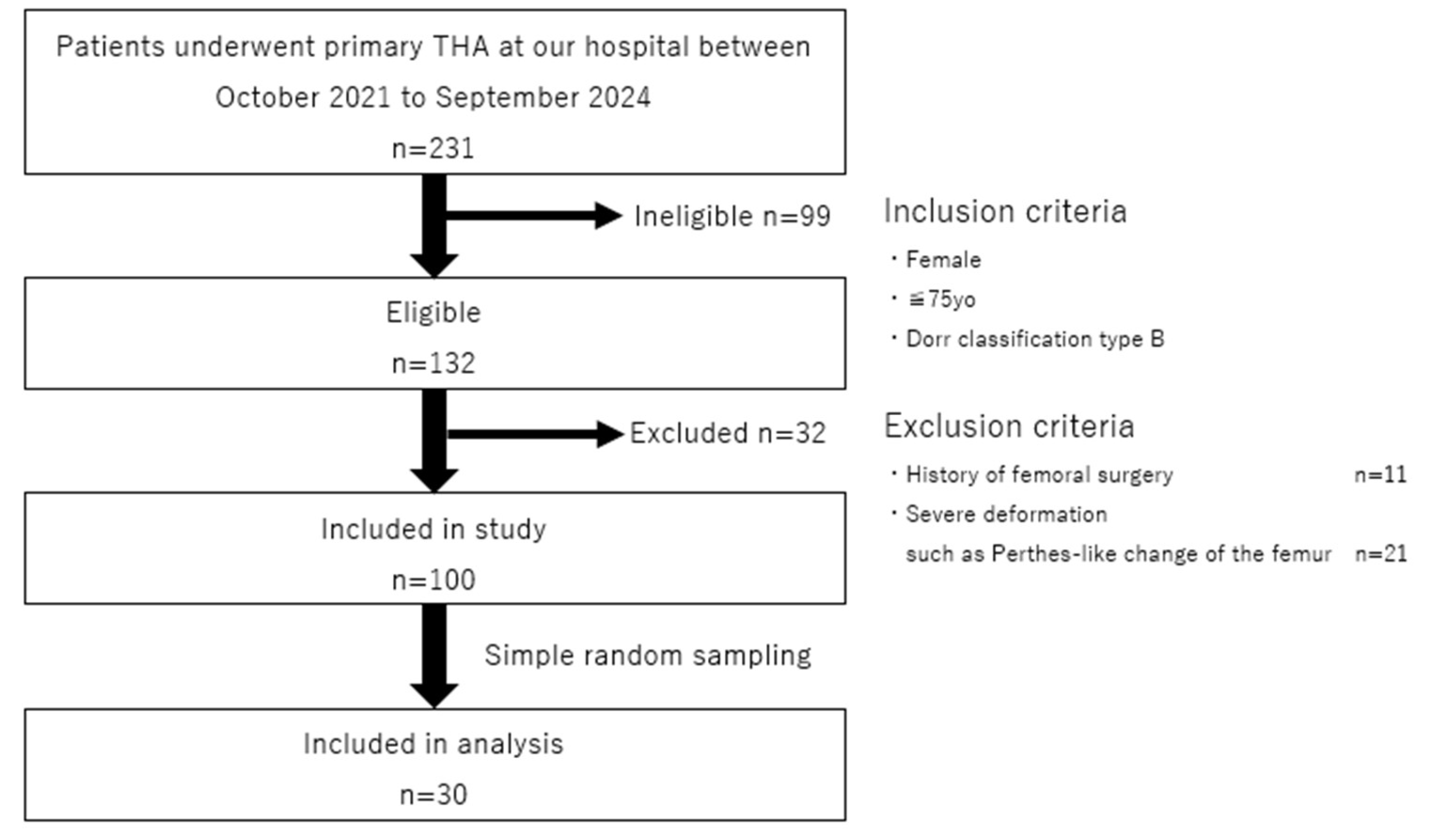
Figure 2.
The 3D-cTHA model was constructed by inserting a stem into a 3D femoral model after the removal of the intramedullary nail. Four stem lengths (130, 140, 150, and 160 mm) were used, with each stem bridging the distal screw-removal hole by 10, 20, 30, and 40 mm, respectively.
Figure 2.
The 3D-cTHA model was constructed by inserting a stem into a 3D femoral model after the removal of the intramedullary nail. Four stem lengths (130, 140, 150, and 160 mm) were used, with each stem bridging the distal screw-removal hole by 10, 20, 30, and 40 mm, respectively.
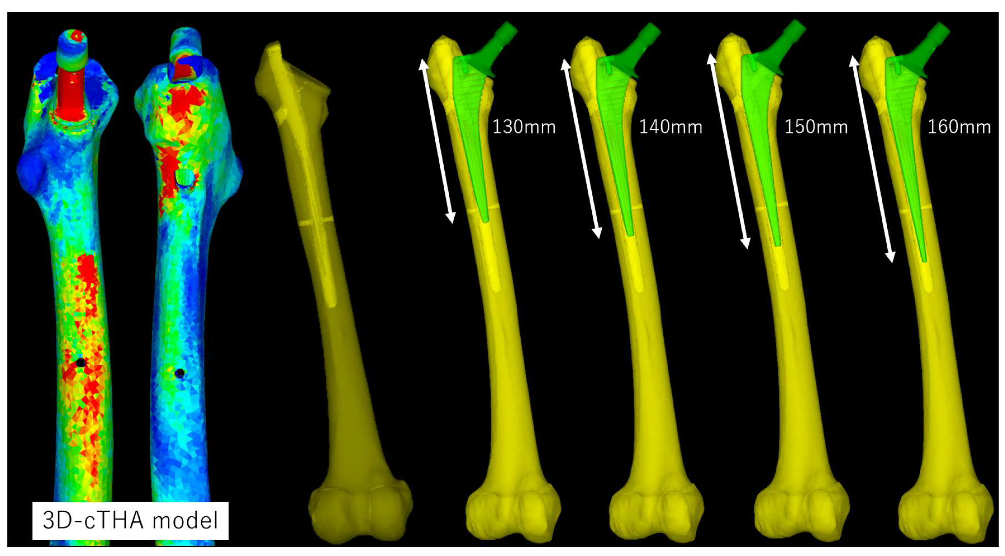
Figure 3.
Preoperative planning for cTHA was performed using the 3D software ZedHip.
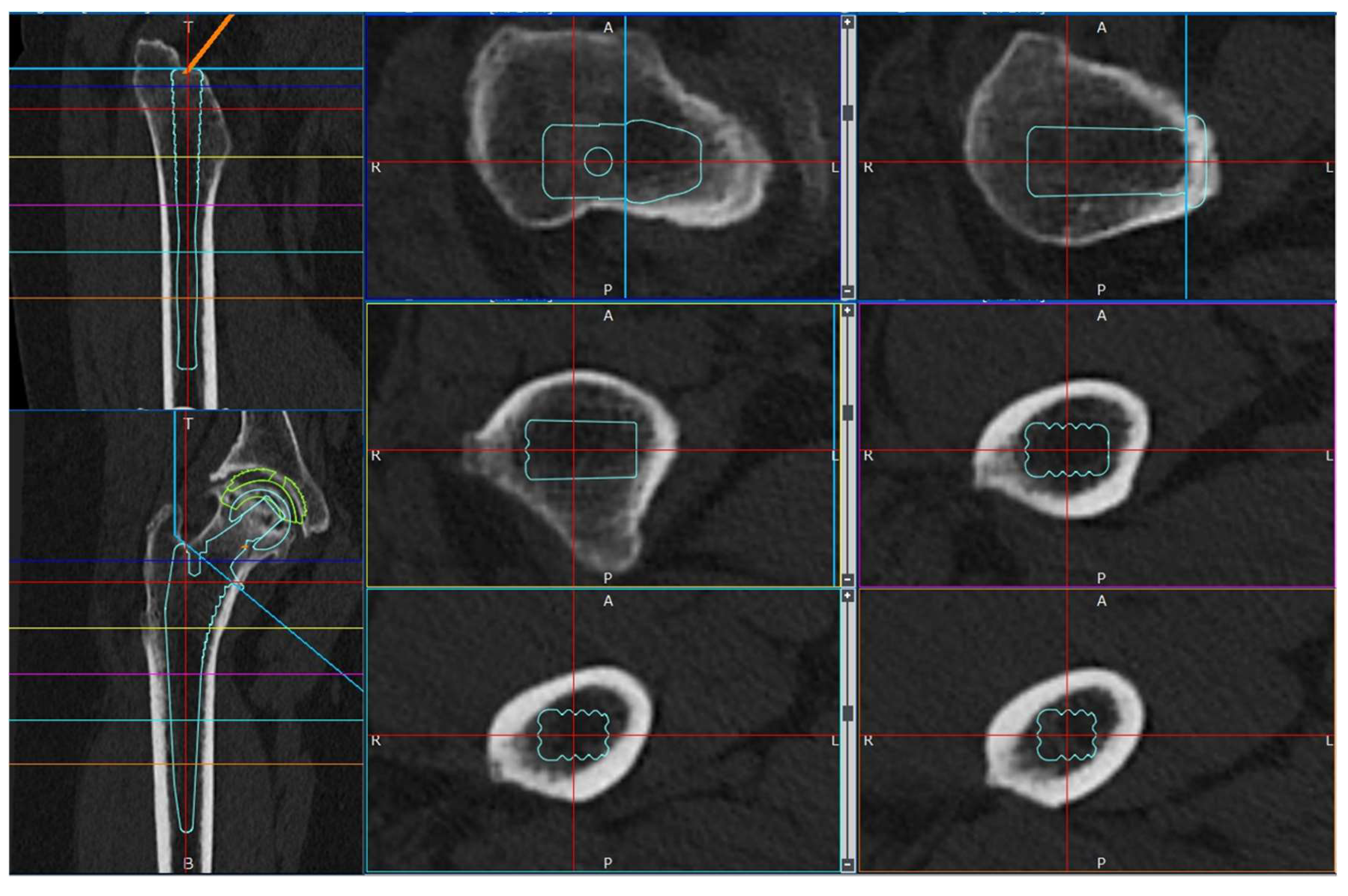
Figure 4.
Load conditions. The points of load application and fixation sites for normal walking and stair climbing are shown. P0 represents the hip-joint contact point; P1 is the point of action of the combined forces from the abductor muscles and iliotibial ligament; P2 is the point of action of the vastus lateralis; and P3 is the point of action of the vastus medialis. In both conditions, the distal femur was fully modeled (highlighted in red).
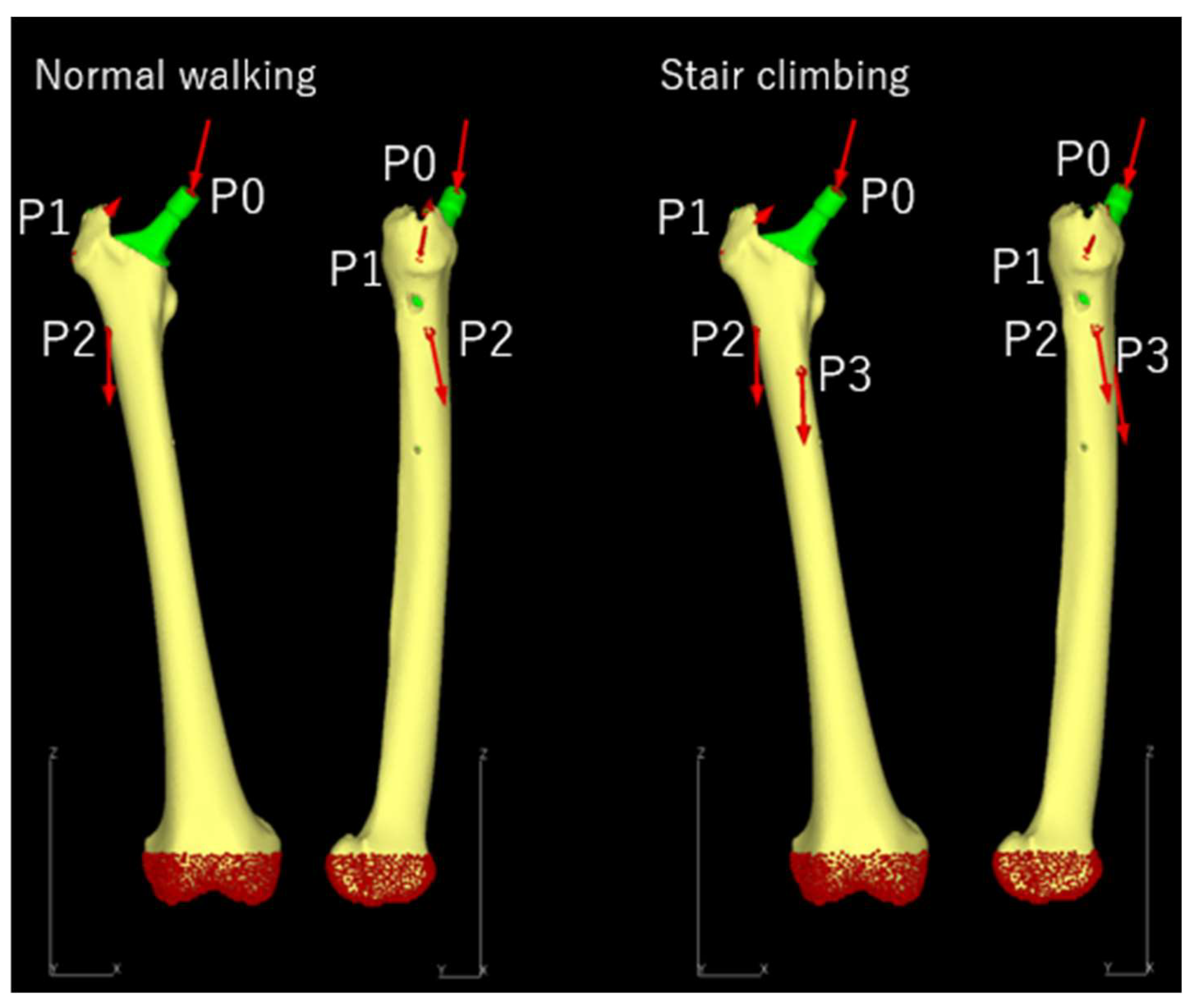
Figure 5.
The region of interest for stress measurement was defined as the shell elements on the bone surface in a spherical area within a 10-mm radius centered around the distal screw-removal hole (highlighted in red).
Figure 5.
The region of interest for stress measurement was defined as the shell elements on the bone surface in a spherical area within a 10-mm radius centered around the distal screw-removal hole (highlighted in red).
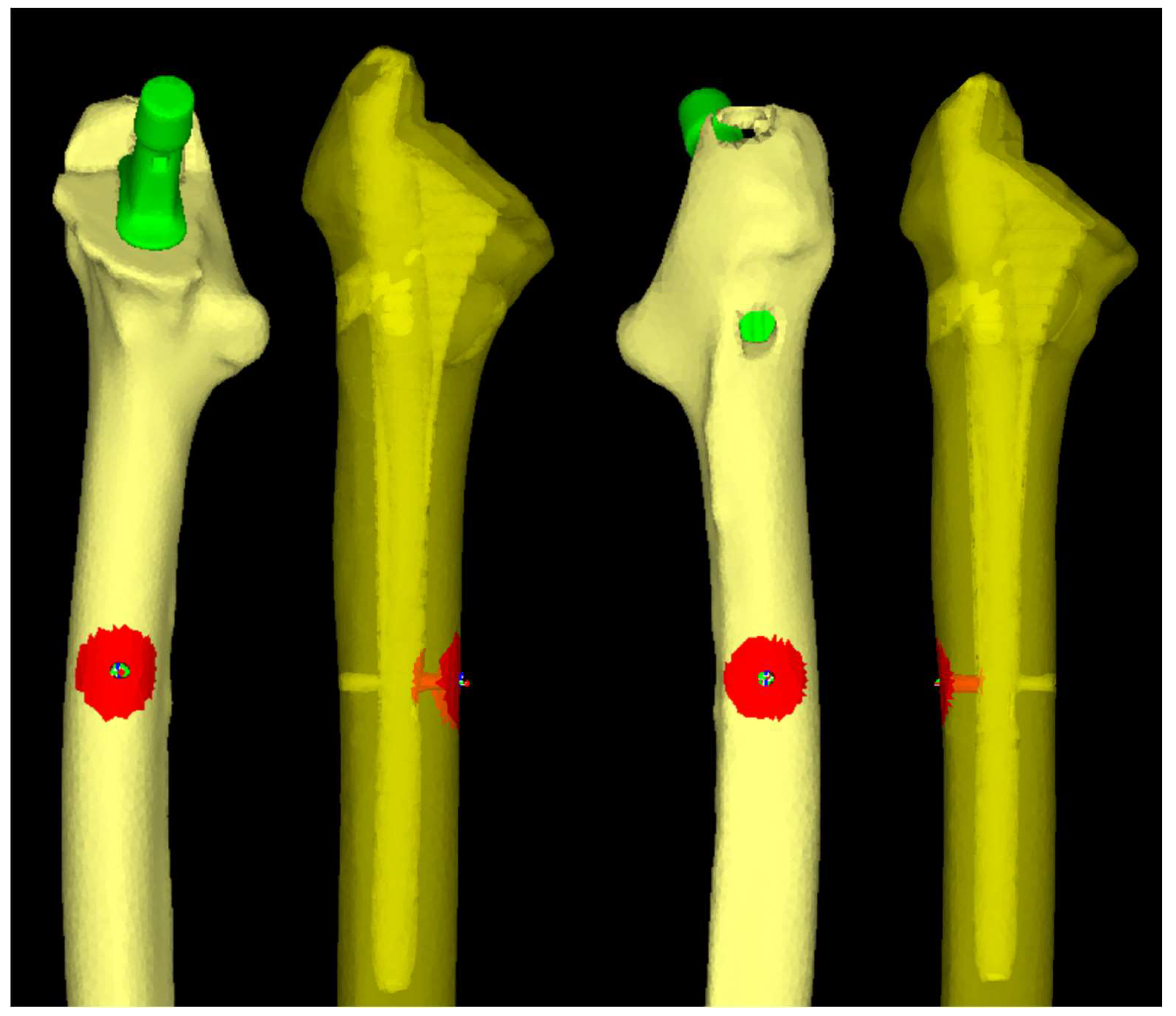
Figure 6.
Histograms of normality tests performed using the Shapiro-Wilk test. (a) Normal walking, (b) Stair climbing. Data in both “normal walking” and “stair climbing” conditions followed a normal distribution.
Figure 6.
Histograms of normality tests performed using the Shapiro-Wilk test. (a) Normal walking, (b) Stair climbing. Data in both “normal walking” and “stair climbing” conditions followed a normal distribution.
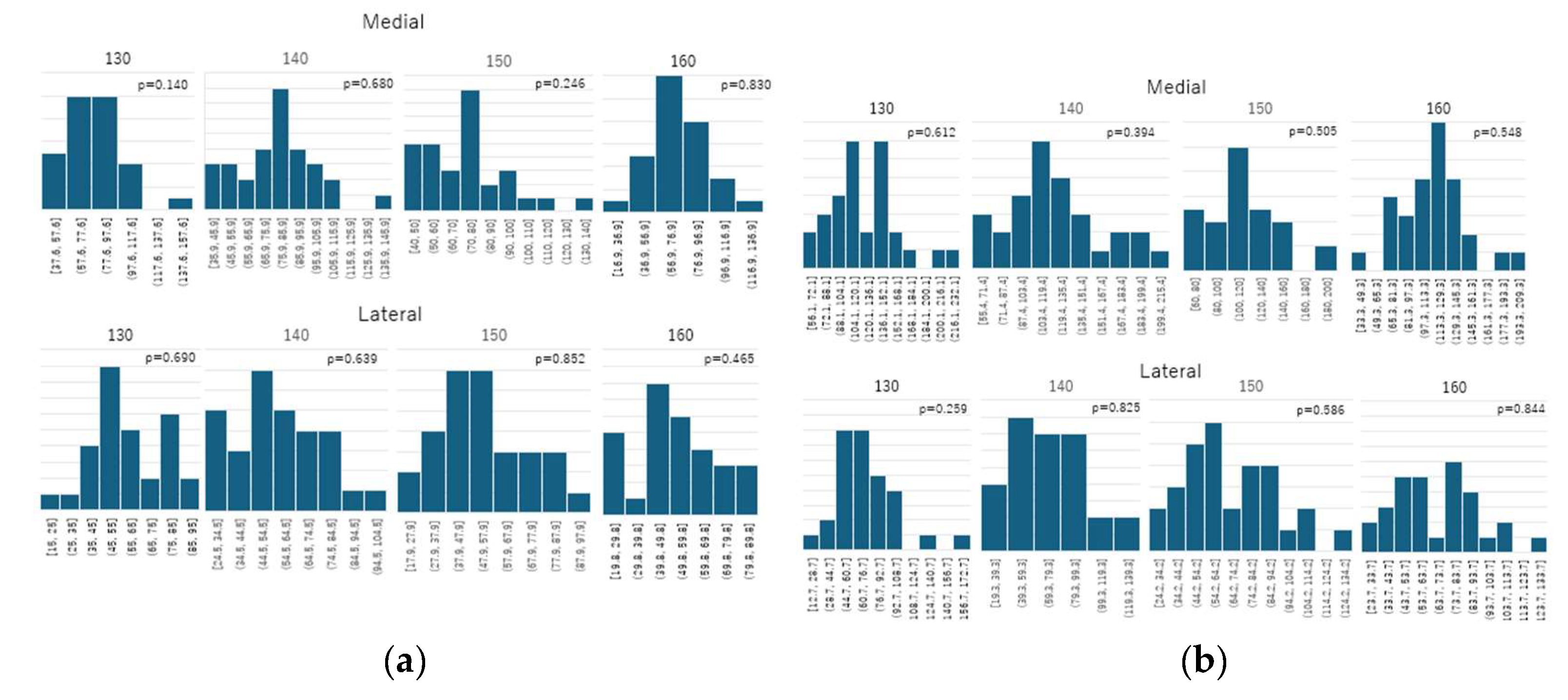
Figure 7.
Comparison of the mean von Mises stress. (a) Normal walking, (b) Stair climbing. In both conditions, the average stress around the distal screw-removal hole decreased as the stem length increased.
Figure 7.
Comparison of the mean von Mises stress. (a) Normal walking, (b) Stair climbing. In both conditions, the average stress around the distal screw-removal hole decreased as the stem length increased.
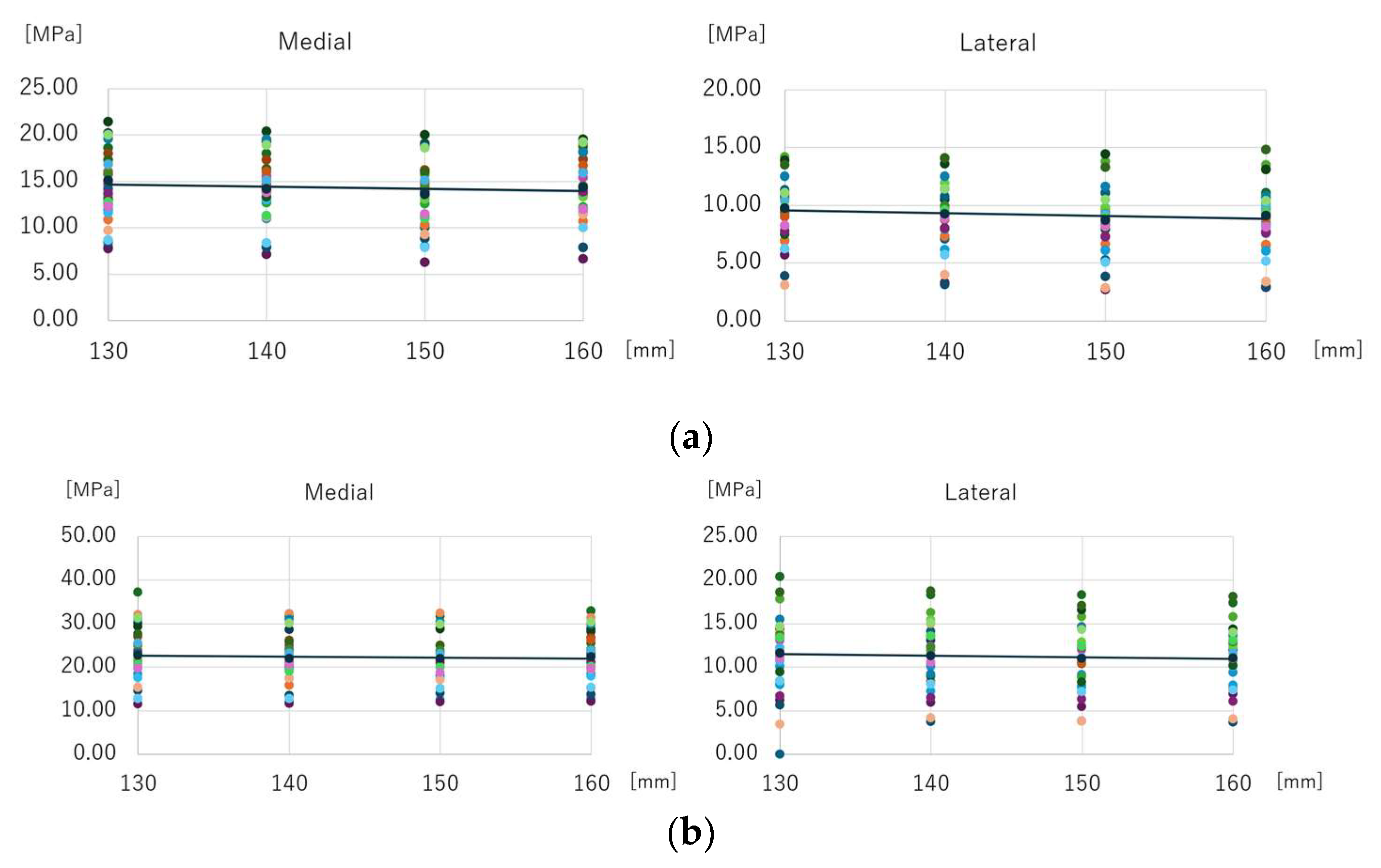
Figure 8.
Comparison of the maximum equivalent stress. (a) Normal walking, (b) Stair climbing. In both conditions, the following results were observed: (1) Compared to the 130-mm stem, the stress was significantly lower for the 150-mm and 160-mm stems. (2) No significant difference was observed between the 150-mm and 160-mm stems. (3) The 140-mm stem showed no significant difference when compared to any other stem length.
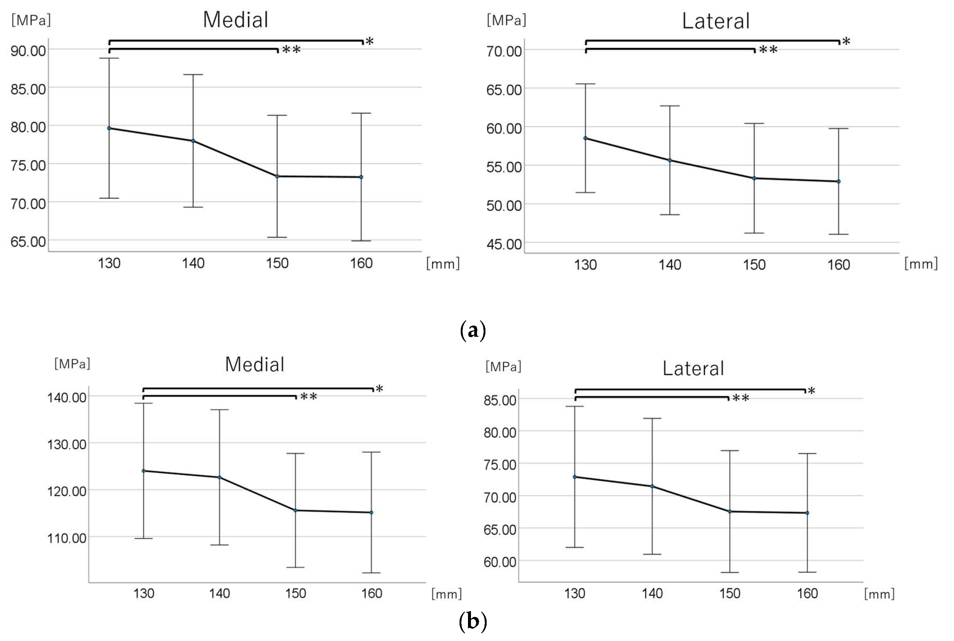

Table 1.
Material parameters.
| Materials | Young’s modulus [GPa] | Poisson’s ratio | |
| Femoral bone | Heterogeneous model | Keyak et al. [45] | 0.40 |
| Stem | Titanium alloy (Ti-6Al-4V) | 109 | 0.28 |
Table 2.
Loading conditions during normal walking and stair climbing.
| Normal walking | |||||
| Force | X (N) | Y (N) | Z (N) | Acting point | % |
| Hip contact | Lt. 54.0 / Rt. −54.0 | 32.8 | −229.2 | P0 | 238 |
| ABD | Lt. 58.0 / Rt. −58.0 | 4.3 | 86.5 | P1 | 104 |
| TFL-P | Lt. 7.2 / Rt. −7.2 | 11.6 | 13.2 | P1 | 19 |
| TFL-D | Lt. −0.5 / Rt. 0.5 | −0.7 | −19.0 | P1 | 19 |
| P1 total force | Lt. −64.7 / Rt. 64.7 | −15.2 | 80.7 | P1 | 105 |
| VL | Lt. −0.9 / Rt. 0.9 | −18.5 | −92.9 | P2 | 95 |
| Stair climbing | |||||
| Force | X (N) | Y (N) | Z (N) | Acting point | % |
| Hip contact | Lt. 59.3 / Rt. −59.3 | 60.6 | −236.3 | P0 | 251 |
| ABD | Lt. 70.1 / Rt. −70.1 | 28.8 | 84.9 | P1 | |
| ITT-P | Lt. 10.5 / Rt. −10.5 | 3.0 | 12.8 | P1 | |
| ITT-D | Lt. −0.5 / Rt. 0.5 | −0.8 | −16.8 | P1 | |
| TFL-P | Lt. 3.1 / Rt. −3.1 | 4.9 | 2.9 | P1 | |
| TFL-D | Lt. −0.2 / Rt. 0.2 | −0.3 | −6.5 | P1 | |
| P1 total force | Lt. −83.0 / Rt. 83.0 | −35.6 | 77.3 | P1 | 119 |
| VL | Lt. −2.2 / Rt. 2.2 | −22.4 | −135.1 | P2 | 137 |
| VM | Lt. −8.8 / Rt. 8.8 | −39.6 | −267.1 | P3 | 270 |
ABD, abductor; TFL, tensor fascia latae; TFL-D, tensor fascia latae-distal; TFL-P, tensor fascia latae-proximal; VL, vastus lateralis; VM, vastus medialis
Table 3.
Participant characteristics and details of the 3D-cTHA model.
| Age [years] | 66.5±8.7 |
| Height [m] | 1.53±0.06 |
| Body weight [kg] | 53.5±9.0 |
| Body mass index [kg/m2] | 22.7±3.2 |
| Side [limb] | Left 16 Right 14 |
| Bone mineral density of the femoral neck [g/cm2] | 0.61±0.13 |
| Canal flare index | 4.17±0.42 |
| Length of distal screw [mm] | 25.7±1.7 |
| Femoral anteversion [degree] | 21.69±10.69 |
Table 4.
Stem length-stratified maximum equivalent stress around the distal screw-removal holes on the medial and lateral sides.
Table 4.
Stem length-stratified maximum equivalent stress around the distal screw-removal holes on the medial and lateral sides.
| Medial | Lateral | |||
| Stem Length, mm | Maximum Equivalent Stress (MPa) | 95% CI (MPa) | Maximum Equivalent Stress (MPa) | 95% CI (MPa) |
| Normal walking | ||||
| 130 | 79.630 | (70.461–88.799) | 58.500 | (51.457–65.543) |
| 140 | 77.970 | (69.284–86.656) | 55.640 | (48.591–62.689) |
| 150 | 73.330 | (65.342–81.318) | 53.310 | (46.203–60.417) |
| 160 | 73.235 | (64.877–81.593) | 52.900 | (46.046–59.754) |
| Stair climbing | ||||
| 130 | 124.017 | (109.607–138.426) | 72.887 | (62.000–83.773) |
| 140 | 122.635 | (108.221–137.050) | 71.427 | (60.941–81.914) |
| 150 | 115.587 | (103.449–127.724) | 67.537 | (58.137–76.937) |
| 160 | 115.147 | (102.283–128.010) | 67.330 | (58.170–76.490) |
Disclaimer/Publisher’s Note: The statements, opinions and data contained in all publications are solely those of the individual author(s) and contributor(s) and not of MDPI and/or the editor(s). MDPI and/or the editor(s) disclaim responsibility for any injury to people or property resulting from any ideas, methods, instructions or products referred to in the content. |
© 2025 by the authors. Licensee MDPI, Basel, Switzerland. This article is an open access article distributed under the terms and conditions of the Creative Commons Attribution (CC BY) license (http://creativecommons.org/licenses/by/4.0/).
Copyright: This open access article is published under a Creative Commons CC BY 4.0 license, which permit the free download, distribution, and reuse, provided that the author and preprint are cited in any reuse.


