
Submitted:
26 December 2024
Posted:
26 December 2024
You are already at the latest version
Abstract
High-sensitivity and large-scale surveys are essential in advancing radio astronomy, enabling detailed exploration of the universe. A Phased Array Feed (PAF) installed in the focal plane of a radio telescope significantly enhances mapping efficiency by increasing the instantaneous Field of View (FoV) and improving sky sampling capabilities. This paper presents the design and optimization of a novel C-Band PAF antenna for the Sardinia Radio Telescope (SRT). The system features an 8×8 array of dual-polarized elements optimized to achieve a uniform beam pattern and an edge taper of approximately 5 dB for single radiating elements within the 3.0–7.7 GHz frequency range. The proposed PAF antenna addresses key efficiency limitations identified in the PHAROS 2 system, including the under-illumination of the SRT's primary mirror caused by narrow sub-array radiation patterns. By expanding the operational bandwidth and refining the radiation characteristics, this new design enables significantly improved performance across the broader frequency range of 3.0–7.7 GHz, enhancing the telescope’s capability for wide-field, high-resolution observations.
Keywords:
Phased Array Feeds
; Broadband Antennas
; Sardinia Radio Telescope
1. Introduction
High sensitivity and survey speed are two critical characteristics for radio astronomical applications: these aspects allow a wide variety of new scientific targets, including studies of galactic gas, magnetic fields, and cosmological surveys of the remote universe. These parameters are directly influenced by the number of radiated beams, the solid angle covered by each beam, the bandwidth, and the system temperature. A known method to enhance these capabilities and increase the Field of View (FoV) of a radio telescope is to observe multiple regions of the sky simultaneously. This can be achieved by increasing the number of radiated beams using either a multi-feed horn system or a Phased Array Feed (PAF).
A PAF, installed at the focal plane of a radio telescope, significantly improves survey speed while expanding the sky sampling capacity compared to traditional multi-feed horn solutions [1,2,3,4]. The PAF typically consists of a planar array of small antenna elements arranged in a well-defined pattern, most commonly a regular two-dimensional grid with an inter-element spacing of approximately half a wavelength at the highest operating frequency. This arrangement ensures optimal sky coverage and sampling while preventing the formation of grating lobes [5-7].
In a PAF, multiple beams can be electronically synthesized by combining signals from different subsets of antenna elements, known as "sub-arrays," using an analog or digital beamforming network controlled by specialized software. Each PAF element contributes to the formation of multiple beams, whose characteristics can be fine-tuned across a wide frequency range by electronically adjusting the phase and amplitude (complex weights) of the element’s signals [8].
The performance of a PAF depends not only on its overall array configuration but also on the radiation patterns of the individual antenna elements. Different antenna layouts, such as patch antennas and folded dipoles, have been explored for this purpose. Among these, Vivaldi antennas are frequently used due to their broad operating bandwidth, low cross-polarization levels, and wide radiated beams [9]. The size and geometry of individual antenna elements influence the beam shape: smaller elements generally exhibit wider radiated beams, while larger elements generate narrower beams. Consequently, the radiation pattern of each individual antenna plays a crucial role in the array overall performance. By carefully combining the amplitudes and phases of multiple PAF elements, it is possible to synthesize beams with the desired shape and characteristics.
The primary component of a radio astronomy receiver is a large parabolic dish that collects and focuses incoming radio waves onto the feed antenna. A key design goal of this receiver is to maximize the G/Tsys ratio, where G is the antenna gain and Tsys is the system noise temperature (including receiver and atmospheric noise). Maximizing G is typically achieved by illuminating the telescope primary reflector with an antenna feed that provides an optimal edge taper of approximately Te≈11 dB [5]. For PAF systems, optimal illumination of the reflector surface can be achieved by carefully adjusting the complex weights of individual array elements and shaping the beams radiated by the sub-arrays to match the dish shape and dimensions. To prevent under-illumination of the reflector caused by overly narrow beams, each antenna element within the array must be designed to produce a sufficiently wide beam, ensuring uniform and effective coverage when the sub-array beams are combined.
The Italian National Institute for Astrophysics (INAF) has made significant advancements in PAF technology, giving a substantial contribution to the state of the art with the development and testing of the PHAROS and PHAROS2 systems [8,10,11,12]. In particular, simulations performed with the PHAROS2 PAF coupled with the Sardinia Radio Telescope (SRT) revealed that, at certain frequencies, the antenna efficiency drops to low levels [10]. This issue was attributed to under-illumination of the reflector caused by the narrow beams generated by a combination of 13 equally weighted antenna elements. Consequently, the system failed to adequately illuminate the SRT dish, reducing overall system performance.
To address this limitation, a new room-temperature PAF demonstrator with a new dedicated antenna is currently under development [13, 14, 15]. This next-generation instrument operates within the C-Band frequency range (4.75–6.00 GHz) and it is designed to be upgradable, covering a wider frequency range, from 3.0 to 7.7 GHz. In this work, we present the design of the new antenna for the PAF demonstrator, which consists of an 8×8 array of dual-polarized unit cells. The single antenna element has been carefully optimized to achieve a uniform beam pattern across the extended operational frequency range. Specifically, the design provides an edge taper of approximately –5 dB in the E-plane or H-plane over the 3.0–7.7 GHz frequency band. This ensures efficient reflector illumination, allowing the PAF to contribute to the formation of the compound beam, and overcomes the limitations identified in the PHAROS2 system, enabling improved performance across the C-Band.
This paper describes in detail a novel approach to design a PAF antenna using a reverse design strategy. Unlike traditional phased array methodologies, which prioritize optimizing the active reflection coefficient (ARC) to minimize signal reflections and ensure good impedance matching across the operating bandwidth and beam-pointing directions, this method focuses on optimizing the radiated field. The innovation of this approach lies in redefining the primary design goal: achieving a specified edge taper (-5 dB in this case) at a designated angle (140° here) in either the E-Plane or H-Plane across the entire frequency range (3–7.7 GHz in this case).
This reverse strategy shifts the emphasis from ARC and impedance matching to superior field performance, making it particularly well-suited for the demanding requirements of radio astronomy applications. By prioritizing edge taper and radiated field characteristics, the proposed method addresses the limitations of conventional phased array designs, offering enhanced beam-shaping capabilities and improved efficiency.
The proposed PAF array was meticulously designed using CST® Microwave Studio, a versatile and widely recognized software for the 3D electromagnetic simulation of microwave components. Over the past two decades, CST has established itself as a reliable and well-validated tool within the electromagnetic community. Its simulation results have consistently demonstrated close agreement with experimental data across a broad spectrum of applications, as documented extensively in the open literature (see, for example, [16-21]).
Fabricating the designed PAF array is a complex and demanding process, requiring access to advanced, specialized technologies and costly infrastructure, which are currently beyond our reach. Consequently, we relied on CST® Microwave Studio to evaluate the performance of the PAF within the array, exploiting its robust simulation capabilities to ensure accurate and dependable assessments.
The presented innovative design will enable improved performance with respect to earlier configurations [6, 7, 10, 25, 39], including increased sensitivity, broader frequency coverage, and enhanced beam-shaping capabilities, ultimately leading to greater survey efficiency and an expanded FoV. The development of advanced phased array feeds, such as the proposed C-Band PAF, represents a significant step forward in radio astronomy instrumentation. These advancements not only improve the telescope observational capabilities but also support more efficient and precise large-scale surveys of the universe.
2. Antenna Design
This section outlines the design procedure for a new C-Band phased array feed (PAF) antenna, intended for installation on the Sardinia Radio Telescope (SRT). The antenna operates over a broad frequency range of 3–7.7 GHz and it is designed to achieve high sensitivity, broadband performance, and versatile multi-beam capabilities to support a variety of observational applications.
The PAF is structured as an 8x8 array consisting of 64 dual-polarized unit cells, resulting in a total of 128 radiating elements. However, only the central 32 unit cells will be actively connected to the back-end system, whereas the remaining elements will be terminated with 50-ohm passive loads. This active region, illustrated in Figure 1, enables the simultaneous generation of multiple independent beams through digital selective sub-array activation [13, 14, 15].
The antenna unit cell design procedure outlined in this work significantly differs from conventional phased array design methods often described in the literature. Traditionally, standard phased array designs focus on optimizing the active reflection coefficient (ARC) to ensure minimal signal reflections and good impedance matching across the operating bandwidth and for various beam pointing directions. The key steps in our design procedure can be summarized as follows:
- Reverse Design Strategy: unlike conventional approaches that prioritize impedance matching, this work adopts a reverse design strategy, starting with radiated field optimization. In our case, the primary design goal is to achieve, for the single antenna of array, a -5 dB edge taper at a 140° angle in either the E-Plane or H-Plane across the full 3–7.7 GHz frequency band. To meet this requirement, both the single unit cell and the finite array model are used. Specifically, only one element of the finite array is fed during the simulation to analyze and optimize the radiated field performance.
- Unit cell ARC optimization: thanks to periodic boundary conditions, this approach assumes an infinite array which provides a reliable approximation for large arrays, such as the 8x8 configuration considered in this work. The active reflection coefficient (ARC) and the active element radiation pattern are computed for the antenna within this infinite array model [22]. For relatively large arrays, where edge elements have minimal influence on the overall performance, this method effectively represents the array behavior with a limited computational cost [23]. In phased array feed (PAF) designs for radio astronomy applications, the optimization process focuses specifically on the scanning angle relative to the broadside direction as a function of the frequency [6, 7, 24, 25]. This ensures that the antenna element delivers optimal impedance matching and minimal signal reflections across the desired operational bandwidth.
- Finite array and pattern analysis: once an acceptable ARC is achieved, the finite array is analyzed. In this step, edge elements are evaluated and, if necessary, adjusted so their impedance closely resembles that of the infinite array. This step also involves examining the array radiated field patterns, beamwidth, side lobe levels, and edge taper.
2.1. Single Antenna Design
In the development of phased array feeds (PAFs) for radio astronomy, the single radiating element of the array is usually an exponential tapered slot antenna (ETSA), commonly known as the "Vivaldi" antenna [6, 7, 26, 27]. These antennas are preferred because of their wide bandwidth, straightforward fabrication, good impedance matching, reasonable gain, and cost-effectiveness. Vivaldi antennas [28,29,30], originally introduced by Gibson [9], fall under the category of Tapered Slot Antennas (TSAs). A TSA employs a flared slot line, fabricated either on a dielectric substrate or in free air, to produce an end-fire radiation pattern over a broad frequency range [31].
In this work, we diverge from the conventional exponential taper profile and instead utilize a linear taper profile, implementing each antenna element on a metallic structure. This design choice provides two key advantages: a wider beam width [32] and enhanced compatibility with cryogenic applications. Metallic structures exhibit lower resistive losses both at room temperature and at cryogenic temperatures, ensuring the PAF maintains high sensitivity—a critical factor for high-performance radio astronomy receivers.
Each TSA antenna in the array, characterized by a linear taper profile (LTSA), consists of two main sections: the propagation section, which guides the signal toward the open end, and the radiation section (Figure 2), which defines the radiation pattern and influences the operational bandwidth [33]. The choice of a linear taper profile rather than an exponential one is driven by specific performance considerations. While an LTSA typically exhibits higher gain than an ETSA, it is less sensitive to variations in the aperture angle [34]. This robustness makes it particularly advantageous for optimizing the edge taper during the design process.
The geometry of a Linear Tapered Slot Antenna (LTSA) is defined by several key parameters that significantly influence its performance: Bulleted lists look like this:
- Taper Length (Lt): The taper length directly affects the bandwidth of the antenna. A longer taper length allows the electromagnetic field to transition more gradually from the feed to the radiating end, resulting in improved directivity and a broader operational frequency range [32];
- Opening angle α: The opening angle determines the antenna shape and aperture, influencing its radiation pattern. Typical values for the opening angle range from 5° to 12° [32]. The taper shape is mathematically described by the linear equation:
- Taper Width (Wt): the taper width, measured at the open end of the antenna, is typically designed using the formula:where fmin is the lowest frequency in the antenna operational range. The taper width, along with the opening angle, determines the effective radiating aperture of the antenna.
- Opening angle α: The feed slot width is critical for achieving optimal impedance matching between the feed line and the radiating aperture. Proper tuning of this parameter minimizes reflection losses, enhances energy transfer efficiency, and improves the overall performance of the antenna.
The layout of a typical LTSA antenna is shown in Figure 2, where all the parameters are clearly depicted. Each of these design aspects contributes to the antenna ability to deliver high efficiency, broad bandwidth, and tailored radiation characteristics.
2.2. Infinite Array Approximation
Integrating LTSA elements into a phased array poses additional challenges compared to their standalone operation, primarily due to the element spacing, which directly influences the array ability to form and steer beams without introducing grating lobes or other distortions. In phased arrays, the spacing Wp between adjacent elements (Figure 3) is typically set between 0.4 and 0.5 λmin, where λmin is the wavelength at the highest operating frequency [35, 36]. Consequently, the taper width Wt must also remain smaller than 0.5 λmin. This spacing adheres to the Nyquist criterion, preventing spatial aliasing and ensuring the integrity of the beamforming process.
Unlike standalone antennas, individual elements within a phased array are subject to mutual coupling effects, which arise from the electromagnetic interactions between neighboring elements. These interactions can significantly alter the antenna input matching, reduce radiation efficiency, and degrade overall array performance. Such effects are particularly detrimental in applications requiring precise beam steering and high sensitivity, such as radio astronomy. Therefore, optimizing the performance of a phased array, particularly in terms of input impedance matching and radiation characteristics, cannot rely solely on simulations of isolated antenna elements in free space.
To address these challenges, an isolated LTSA element with a taper width ranging from 0.4 to 0.5 λmin was initially simulated in free space. While this setup demonstrated acceptable impedance matching, the bandwidth performance was limited due to the absence of neighboring elements and mutual coupling effects. To gain a more realistic understanding of the antenna behavior in an array configuration, we employed the “unit cell” infinite array approximation. This method models an infinite periodic array where each antenna element is surrounded by identical ones, periodically repeating elements in the two directions identified by the array plane.
The infinite array approximation is particularly effective and gives a realistic modelling for analyzing mutual coupling in large arrays, where central elements experience uniform interactions from their immediate neighbors. This technique provides a practical and accurate framework for evaluating the performance of phased arrays, especially in applications like radio astronomy, where precise modeling of mutual coupling and array interactions is essential. It has been widely adopted in the design of large-scale phased arrays [22, 37, 38] and phased array feeds (PAFs) for radio astronomy [7, 24, 25].
2.3. Unit Cell Characteristics and Intial Settings
This section provides a detailed description of the unit cell geometry, its key parameters, and the rationale behind their selection. The design must comply with the Nyquist sampling criterion while achieving the wide operational bandwidth between 3 and 7.7 GHz. To meet these requirements, careful attention was given to the selection of the critical physical parameters such as the spacing between elements (Wp) and the taper length (Lt). The initial settings for these parameters were established as follows:
- Element Spacing Wp= λmin/2 = 19.48 mm: where λmin is the wavelength corresponding to the highest frequency (7.7 GHz). This spacing adheres to the Nyquist sampling criterion, ensuring the prevention of grating lobes in the array radiation pattern across the wide frequency range. By maintaining the selected value of Wp throughout the unit cell optimization process, the risk of grating lobes across the frequency range is effectively minimized, which is essential for preserving the array performance at higher.
- Taper Length Lt= λmax/2 = 50 mm, where λmax corresponds to the wavelength at the lowest frequency (3 GHz). Unlike Wp, Lt is subject to optimization to meet specific edge taper and bandwidth requirements. Adjustments to Lt, and consequently the opening angle α, play a significant role in shaping the radiation beam characteristics to achieve a consistent and desirable edge taper across the entire operational bandwidth.
To balance structural integrity and compactness, the radiating walls of the unit cell are constructed with a metal thickness of 3 mm. This dimension ensures sufficient mechanical stability while maintaining a lightweight and compact design, which is a crucial aspect for the dense antenna arrangement required in the PAF array.
The unit cell design employs a dual-polarized configuration, incorporating two orthogonally positioned linearly tapered slot antennas (LTSAs). These antennas are particularly suited for wideband applications due to their tapered slot profile, which supports high efficiency across the broad frequency range. Each LTSA operates independently, enabling the unit cell to accommodate two orthogonal polarizations:
- Horizontal Polarization: one LTSA in each unit cell is oriented to radiate in the horizontal plane, efficiently capturing signals aligned with this polarization.
- Vertical Polarization: The second LTSA is aligned to radiate in the vertical plane, enhancing the unit cell dual-polarization capability.
By arranging the antennas with a rotation of 90 degrees relative to each other, the unit cell minimizes cross-polarization interference, a crucial factor for maintaining signal integrity [23]. This orthogonal configuration significantly improves the detection of faint signals across both polarizations, which is vital for radio astronomical applications. Enhanced sensitivity and clarity in both polarization channels directly contribute to improved detection accuracy in such applications. Figure 4a illustrates the layout of the unit cell, highlighting the dual-polarized configuration and the orientation of the LTSAs for horizontal and vertical polarization.
The feeding network of each individual antenna in the array plays a critical role in ensuring proper impedance matching across the entire operational frequency band. The propagation section is designed as an “L”-shaped slot, optimized with seven tunable parameters, as illustrated in Figure 4b. This design enables precise control over the antenna impedance characteristics to maintain efficient energy transfer over the wide frequency range.
The LTSA is fed using a 50-ohm integrated coaxial cable, which employs air as the dielectric medium. To embed this feeding structure within the antenna, a cylindrical channel with a diameter d=1 mm is milled directly into the antenna body. This innovative approach seamlessly integrates the coaxial feed into the antenna structure, eliminating external attachments and their associated challenges. The antenna fabrication process involves manufacturing it in two distinct parts. One part is designed to house the coaxial probe, which is then inserted into the other part. This assembly approach simplifies the precise alignment of the central conductor of the coaxial cable within the milled channel, significantly reducing the risk of assembly errors. By eliminating the need for soldering, this design minimizes potential mechanical failures and prevents impedance mismatches caused by misaligned or incorrectly positioned external coaxial cables.
The central conductor of the coaxial feed has a diameter of 0.435 mm, which is carefully selected to ensure compatibility with the antenna impedance requirements. Figure 5 provides a detailed depiction of the coaxial feed probe integration, highlighting the cylindrical channel milled into the antenna structure to facilitate precise and seamless assembly.
2.3. PAF Antenna Design
The first step in designing the PAF antenna involves optimizing the geometric parameters of the unit cell LTSA antenna (Figure 2) to achieve a -5 dB edge taper in the H-plane at a 140° angle, over the operational frequency range of 3 to 7.7 GHz. To meet this requirement, an extensive series of parametric simulations was conducted to optimize the radiated field. The proper impedance matching between the unit cell and the external feeding network will be performed in the last step of the design process. In our approach, the PAF antenna design represents a careful balance between achieving the desired beamwidth and maintaining impedance matching across the bandwidth.
While adjusting the beam radiated by a single antenna, it is crucial to account for mutual coupling effects caused by the interactions with neighbouring elements in the array. These interactions prevent edge taper optimization using a single, isolated antenna in free space. To address this, a 128-element array was introduced as a prototype of the PAF antenna. The layout of this phased array feed, with dual-polarized capabilities, is illustrated in Figure 6a.
The edge taper optimization was performed using a selective activation procedure. In this process, only specific elements of the array, referred to as the active zone, were fed, while the remaining elements were connected to passive loads to simulate mutual coupling effects. The feeding configuration for the active zone is shown in Figure 6b. In this setup, antenna element number 93, located at the center of the array grid, was activated to achieve the desired field taper across the array. This configuration allows to model and incorporate the mutual coupling effects into the optimization process, refining the edge taper for the active zone.
The edge taper specifications were achieved by adjusting the taper length Lt and, consequently, the opening angle α of the LTSA. In LTSA designs, α typically ranges from 5° to 12°, and it directly influences the width of the radiated field [32]. For isolated antennas, when the ratio Lt/λ0 ≤ 2 (where λ0 is the wavelength), the radiated beamwidth increases significantly in both the E-plane and H-plane [32, 34]. Additionally, Lt is proportional to the operational bandwidth [30]; therefore, in this study, taper lengths exceeding λmax were avoided to prevent an excessively large radiant structure.
Different values of Lt were tested to determine the optimal configuration. As shown in Figure 7, keeping both the element spacing Wp and width Wt constant at 19.48 mm and 16.48 mm, respectively, the opening angle α increases for decreasing values of taper length Lt. Consequently, the radiated field narrows progressively in the H-plane. This relationship demonstrates how taper length adjustments directly influence the beamwidth, enabling fine-tuning of the edge taper for optimal performance.
The variation of taper length Lt has a pronounced impact on the edge taper in the H-plane, particularly for frequencies below 5.25 GHz. In this range, the taper width is highly sensitive to changes in Lt. However, for frequencies between 5.25 GHz and 7.7 GHz, this effect becomes less significant, with the edge taper stabilizing between 140° and 160°. In contrast, in the E-plane, the edge taper shows minimal sensitivity to variations in Lt, remaining consistently below 140° for frequencies above 3.5 GHz, as shown in Figure 8.
The design specifications for the H-plane are met when Lt=70 mm, corresponding to an opening angle α≈6.5°. This configuration ensures a -5 dB edge taper greater than 140° across the entire frequency range of 3 to 7.7 GHz. Figure 9 and Figure 10 present the normalized simulated radiation patterns of the single powered LTSA antenna in both the H-plane and E-plane at frequencies of 3 GHz, 5.5 GHz, and 7.7 GHz, demonstrating the optimized radiation performance.
With the radiated field successfully optimized to achieve the required edge taper, the next design step focuses on refining the active reflection coefficient (ARC) to ensure proper impedance matching. This step employs an infinite array model (described in the previous section as the unit cell array approach) to align the antenna performance with the feed network requirements. Using the optimized Lt value obtained in the previous step (Lt =70 mm), care was taken to preserve the radiated field configuration while fine-tuning the slot widths and parameters of the “L-shaped” slot to achieve optimal impedance matching across the 3-7.7 GHz frequency band (refer to Figure 4b for the antenna geometry). Key geometric parameters of the optimized unit cell include: L1=7.5 mm, L2=3.5 mm, L3=3.5 mm, L4=2.5 mm, L5=3.3 mm, Wa=0.5 mm, Ws=1.1 mm, whereas the total length of the single radiating element along the z-axis is 87 mm. The optimized unit cell exhibits excellent performance, achieving an ARC below -12 dB across the operational bandwidth and below -14 dB in the frequency range of 3 to 7.2 GHz. Furthermore, the mutual coupling between the two orthogonally polarized LTSA antennas of the unit cell is below -24 dB, as shown in Figure 11.
To account for edge effects and further validate the design, a finite array model was created by adding 16 additional elements along the two open sides of the array, increasing the total number of antennas to 144. This configuration is depicted in Figure 12, which illustrates the strategic placement of the additional elements to form an artificial buffer zone along the array boundaries.
By incorporating these boundary elements, the active antennas near the center of the array exhibit an ARC that closely resembles that of the isolated unit cell. Figure 13 compares the ARC of antenna 93 (located at the center of the array) with that of the unit cell, demonstrating excellent agreement. It is worth noting that the results for the edge taper remain consistent with those shown in Figure 7 and Figure 8, confirming that the addition of boundary elements does not compromise the radiated field performance.
The proposed PAF antenna represents a significant advancement over the state-of-the-art designs presented in Table 1. It achieves an optimal combination of the widest operational bandwidth, compact element spacing, and a highly optimized single-element design (LTSA). These features collectively enhance its beam-forming capabilities and adaptability to a wide range of applications. A detailed analysis of its performance trade-offs and advantages reveals the following key attributes:
- Operational bandwidth: The proposed design boasts the broadest operational bandwidth, surpassing conventional designs such as [6,25]. This makes it particularly suitable for applications requiring high-frequency agility, such as radio astronomy. The extended bandwidth also facilitates use across multiple sub-bands, covering a range from 2.53 to 9 GHz.
- Compactness and resolution: The proposed antenna strikes an excellent balance between compactness and resolution, featuring a moderate array size of 144 elements. This provides adequate resolution while maintaining manageable system complexity. By contrast, [6] achieves higher resolution with 320 elements but at the expense of increased size and processing demands.
- Design innovation: The use of LTSA elements optimizes the antenna for broadband performance, offering a distinct advantage over the more common ETSA elements used in other designs. While Bowtie elements in [39] offer compactness, they are less effective for wideband applications.
3. Conclusions
This paper introduces the design and optimization of an innovative C-Band phased array feed (PAF) antenna tailored for the Sardinia Radio Telescope (SRT). The antenna comprises an 8×8 array of dual-polarized elements, engineered to produce a uniform beam pattern and achieve an edge taper of approximately 5 dB for each radiating element within the 3.0–7.7 GHz frequency range. This advanced PAF antenna overcomes key efficiency challenges identified in the PHAROS 2 system, including the inadequate illumination of the SRT primary mirror due to the narrow radiation patterns of sub-arrays. The design methodology and finite array modeling presented in this work mark a significant advancement in phased array feed (PAF) systems for radio astronomy. Departing from the conventional ARC-first design approach, this methodology prioritizes achieving precise edge taper control and optimizing radiated field characteristics before addressing impedance matching.
The integration of finite array modeling, enhanced with boundary elements to mitigate mutual coupling and edge effects, ensures consistent performance across the operational bandwidth. This approach provides uniform illumination of the Sardinia Radio Telescope (SRT) primary reflector, leading to improved sensitivity for radio observations.
This tailored design strategy not only addresses the specific requirements of the SRT but also establishes a robust framework for developing high-performance phased arrays in broader radio astronomy applications. It emphasizes precision in field characteristics and effective mutual coupling management, making it highly suited for the demanding performance standards of modern radio astronomy.
In conclusion, the proposed PAF antenna sets a new benchmark in the field, offering unmatched performance across multiple parameters, making it an ideal candidate for demanding and versatile applications like radio astronomy.
Author Contributions
Conceptualization, P.M. and A.N.; methodology, P.M.; CST® EM simulations, P.M. and G.V.; validation, P.M., G.A.C.; formal analysis, P.M.; data curation, P.M.; writing—original draft preparation, P.M and G.A.C.; writing—review and editing P.M., G.A.C., G.M.1 and G.M.2, supervision, A.N. and T.P.; project administration, A.N. and T.P. All authors have read and agreed to the published version of the manuscript.
Funding
This research received no external funding
Acknowledgments
We gratefully thank to dr. Andrea Melis (INAF) and dr. Alessandro Cabras (INAF) for the OAC-CED hardware support in the heavy EM simulations. Special thanks to dr. Pierluigi Ortu (INAF) for his logistical support.
Conflicts of Interest
The authors declare no conflicts of interest.
Abbreviations
The following abbreviations are used in this manuscript:
| PAF | Phased Array Feed |
| SRT | Sardinia Radio Telescope |
| FoV | Field of View |
| INAF | Italian National Institute for Astrophysics |
| OAC | Astronomical Observatory of Cagliari |
| CED | Data Elaboration Center |
| ARC | Active Reflection Coefficient |
| TSA | Tapered Slot Antenna |
| ETSA | Exponential Tapered Slot Antenna |
| LTSA | Linear Tapered Slot Antenna |
| EM | Electromagnetic |
References
- Ivashina, M.V.; Kehn, M.N.M.; Kildal, P.; Maaskant, R. Decoupling Efficiency of a Wideband Vivaldi Focal Plane Array Feeding a Reflector Antenna. IEEE Transaction on Antennas and Propagation 2009, 57, 373–382. [Google Scholar] [CrossRef]
- Fisher, J.R.; Bradely, R.F. Full-sampling array feeds for radio telescopes. In Proceedings of the SPIE Astronomical Telescopes and Instrumentation, Munich, Germany, 3 July 2000. [Google Scholar] [CrossRef]
- Warnick, K.F.; Maaskant, R.; Ivashina, M.V.; Davidson, D. B.; Jeffs, B.D. High-Sensitivity Phased Array Receivers for Radio Astronomy. Proceedings of the IEEE 2016, 104, 607–622. [Google Scholar] [CrossRef]
- Roshi, D.A.; Shillue, D.W.; Simon, B.; Warnick, K.F.; Jeffs; Pisano, B.D.J.; Prestage, R.; White, S.; Fisher, J.R.; Morgan, M.; et al. Performance of a highly sensitive, 19-element, dual-polarization, cryogenic L-band phased array feed on the Green Bank Telescope. Astron. J. 2018, 155, 18. [Google Scholar] [CrossRef]
- Goldsmith, P.F. Quasi-optical Techniques. Proceedings of the IEEE 1992, 80. [Google Scholar] [CrossRef]
- Raid, E.W.; Ortiz-Balbuena, L.; Ghadiri, A. A 324-Element Vivaldi Antenna Array for Radio Astronomy Instrumentation. IEEE Transaction on Instrumentation and Measurement 2012, 61. [Google Scholar] [CrossRef]
- Locke, L.; Garcia, D.; Halman, M.; Henke, D.; Hovey, G.; Jiang, N.; Knee, L.; Lacy, G.; Loop, D.; Rupen, M.; Veidt, B.; Wierzbicki, R. CryoPAF4 – A Cryogenic Phased Array Feed Design. SPIE Astronomical Telescopes and Instrumentation, Edinburgh, United Kingdom, 2016. [Google Scholar] [CrossRef]
- Navarrini; Scalambra, A.; Rusticelli, S.; Maccaferri, A.; Cattani, A.; Perini, F.; Ortu, P.; Roda, J.; Marongiu, P.; Saba, A.; Poloni, M.; Ladu, A.; Schirru, L. The Room Temperature Multi-Channel Heterodyne Receiver Section of the PHAROS2 Phased Array Feed. Electronics 2019, 8, 666. [Google Scholar] [CrossRef]
- Gibson, P.J. The Vivaldi Aerial. In Proceedings of the 9th European Microwave Conference, Brighton, UK, October 1979. [Google Scholar] [CrossRef]
- Navarrini; Nesti, R.; Schirru, L. Electromagnetic simulation and beam-pattern optimization of a C-band Phased Array Feed for the Sardinia Radio Telescope. 2019 IEEE 2nd Ukraine Conference on Electrical and Computer Engineering (UKRCON), Lviv, Ukraine, 2019; pp. 137–143. [Google Scholar] [CrossRef]
- Navarrini; et al. The Warm Receiver Section and the Digital Backend of the PHAROS2 Phased Array Feed. 2019 IEEE International Symposium on Phased Array System & Technology (PAST), Waltham, MA, USA, 2019; pp. 1–8. [Google Scholar] [CrossRef]
- Schirru, L.; Pisanu, T.; Navarrini, A.; Urru, E.; Gaudiomonte, F.; Ortu, P.; Montisci, G. Advantages of Using a C-band Phased Array Feed as a Receiver in the Sardinia Radio Telescope for Space Debris Monitoring. 2019 IEEE 2nd Ukraine Conference on Electrical and Computer Engineering (UKRCON), Lviv, Ukraine, 2019; pp. 133–136. [Google Scholar] [CrossRef]
- Navarrini; et. Al. Architecture of C-band Phased Array Feed with RFSoC digital beamformer. 2022 3rd URSI Atlantic and Asia Pacific Radio Science Meeting (AT-AP-RASC), Gran Canaria, Spain, 30 May - 04 June 2022. [Google Scholar] [CrossRef]
- Maxia, P.; Pisanu, T.; Cabras, A.; Pilia, S.; Caocci, R.; Ortu, P.; Melis, A.; Navarrini, A.; Di Ninni, P.; Nesti, R.; Comoretto, G.; Schirru, L.; Belluso, M.; Ladu, A.; Marongiu, P.; Billotta, S. Progress in the design of the front-end of the C-Band PAF prototype for the SRT Primary Focus. Proceedings of 2024 4th URSI Atlantic Radio Science Meeting (AT-RASC), Meloneras, Spain, 19-24 May 2024. [Google Scholar] [CrossRef]
- Pisanu, T.; Maxia, P.; Cabras, A.; Schirru, L.; Ortu, P.; Melis, A.; Navarrini, A.; Belluso, M.; Billotta, S.; Comoretto, G.; Concu, R.; Di Ninni, P.; Ladu, A.; Marongiu, P.; Nesti, R. Status of a C-band Phased Array Feed with RFSoC digital beamformer. Proceedings of 2023 XXXVth General Assembly and Scientific Symposium of the International Union of Radio Science (URSI GASS), Sapporo, Japan, 19-26 August 2023. [Google Scholar] [CrossRef]
- Cicchetti, R.; Cicchetti, V.; Faraone, A.; Foged, L.; Testa, O. A Compact High-Gain Wideband Lens Vivaldi Antenna for Wireless Communications and Through-the-Wall Imaging. IEEE Transactions on Antennas and Propagation 2021, 3177–3192. [Google Scholar] [CrossRef]
- Wang, M.; Crocco, L.; Li, M.; Cavagnaro, M. Slot-Loaded Vivaldi Antenna for Biomedical Microwave Imaging Applications: Influence of Design Parameters on Antenna’s Dimensions and Performances. Sensors 2024, 24, 5368. [Google Scholar] [CrossRef]
- Hu, R.; Zhang, F.; Ye, S.; Fang, G. Ultra-Wideband and High-Gain Vivaldi Antenna with Artificial Electromagnetic Materials. Micromachines 2023, 14, 1329. [Google Scholar] [CrossRef]
- Sun, H.; Lee, Y.H.; Luo, W.; Ow, L.F.; Yusof, M.L.M.; Yucel, A.C. Compact Dual-Polarized Vivaldi Antenna with High Gain and High Polarization Purity for GPR Applications. Sensors 2021, 21, 503. [Google Scholar] [CrossRef]
- Ullah, R.; Ullah, S.; Faisal, F.; Ullah, R.; Choi, D.; Ahmad, A.; Kamal, B. High-Gain Vivaldi Antenna with Wide Bandwidth Characteristics for 5G Mobile and Ku-Band Radar Applications. Electronics 2021, 10, 667. [Google Scholar] [CrossRef]
- Saleh, S.; Saeidi, T.; Timmons, N. Simple Compact UWB Vivaldi Antenna Arrays for Breast Cancer Detection. Telecom 2024, 5, 312–332. [Google Scholar] [CrossRef]
- Mailloux, R.J. Phased Array Antenna Handbook, 2nd edition; Artech House, 2005; ISBN 1-58053-689-1. [Google Scholar]
- Rutschlin, M.; Iluz, Z. Phased Array Design with CST STUDIO SUITE. proceedings of 10th European Conference on Antennas and Propagation (EUCAP), Davos, Switzerland, 10-15 April 2016. [Google Scholar] [CrossRef]
- Arts, M.; Ivashina, M.; Iupikov, O.; Bakker, L.; Van der Brink, R. Design of a Low-Loss Low-Noise Tapered Slot Phased Array Feed for Reflector Antennas. proceedings of 4th European Conference on Antennas and Propagation (EUCAP), Barcelona, Spain, 12-16 April 2010. [Google Scholar]
- McCulloch, M.A.; M., D'Cruze; Grainge, K.; Keith, M.; Melhuish, S. A S-Band Cryogenic Phased Array Feed for Radio Astronomy. RAS Techniques and Instruments 2023, 2, 432–440. [Google Scholar] [CrossRef]
- Kindt, R.W.; Pickles, W.R. Ultrawideband All-Metal Flared-Notch Array Radiator. IEEE Transaction on Antennas and Propagation, IEEE Transactions on Antennas and Propagation 2010, 58. [Google Scholar] [CrossRef]
- Yan, J.; Gogineni, S.; Camps-Raga, B.; Brozena, J. A Dual-Polarized 2-18 GHz Vivaldi Array for Airborne Radar Measurements of Snow. IEEE Transactions on Antennas and Propagation 2016, 64. [Google Scholar] [CrossRef]
- Shin, J.; Schaubert, D.H. A Parameter Study of Stripline-Fed Vivaldi Notch-Antenna Array. IEEE Transactions on Antennas and Propagation 1999, 47. [Google Scholar] [CrossRef]
- Dhawan, R.; Kaur, G. Vivaldi Antenna Simulation on Defining Parameters, parametric study and results. JCTA 2016, 9, 5129–5138. [Google Scholar]
- Johnson, R.C. Antenna Engineering Handbook; Mc Graw-Hill, 1984; ISBN 0-07-032381-X. [Google Scholar]
- Milligan, T.A. Modern Antenna Design, second edition; Wiley & Sons, 2005; ISBN 13 978-0-471-45776-3. [Google Scholar]
- Yngvesson, K.S.; Korzeniowski, T.L.; Kim, Y.; Kollberg, E.L.; Johansson, J.F. The Tapered Slot Antenna – A New Integrated Element for Millimeter-Wave Applications. IEEE Transactions on Microwave Theory and Techniques 1989, 37. [Google Scholar] [CrossRef]
- Madhav, P.V.; Prasad, M.S.G. Characterization of Printed Podal Vivaldi Antenna on RT Duroid with Single and Double Cavity. International Journal of Recent Technology and Engineering (IJRTE) 2019, 7, 1984–1989. [Google Scholar] [CrossRef]
- Yngvesson, K.S.; Shaubert, D.H.; Korzeniowski, T.L.; Kollberg, E.L.; Thungren, T.; Johansson, J.F. Endfire Tapered Slot Antennas on Dielectric Substrates. IEEE Transactions on Antennas and Propagation 1985, AP-33. [Google Scholar] [CrossRef]
- Hayman, D.B. Beamforming and Evaluation of Focal Plane Arrays for Radio Astronomy. PhD thesis, Macquarie University, Sidney, Australia, 2011. [Google Scholar]
- Ivashina, M.V.; Kehn, M.N.M.; Kildal, P. Optimal Number of Elements and Elements Spacing of Wide-Band Focal Plane arrays for a New Generation Radio Telescopes. Proceedings of Second European Conference on Antennas and Propagation (EuCAP), Edinburgh (UK), 1-16 November 2007; 2007. [Google Scholar] [CrossRef]
- Kahkonen, H.; Ala-Laurinaho, J.; Viikari, V. A Modular Dual-Polarized Ka-Band Vivaldi Antenna Array. IEEE Access 2022, 10, 36363–36372. [Google Scholar] [CrossRef]
- Kahkonen, H.; Ala-Laurinaho, J.; Viikari, V. Dual-Polarized Ka-Band Vivaldi Antenna Array. IEEE Transactions on Antennas and Propagation 2020, 68, 2675–2683. [Google Scholar] [CrossRef]
- Fan, J.; Yang, J.; Yan, Y.; Zhu, K.; Jiang, P.; Cao, H.; Ma, J.; Li, B.; Pantaleev, M. Design of Octave-Bandwidth Phased Array Feed for Large Radio Telescope. 13th European Conference on Antennas and Propagation (EuCAP), Krakow, Poland, 31 March – 05 April 2019; ISBN 978-88-907018-8-7. [Google Scholar]
Figure 1.
Simplified layout of the 64-element array, showing the central 32 active elements highlighted in orange.
Figure 1.
Simplified layout of the 64-element array, showing the central 32 active elements highlighted in orange.
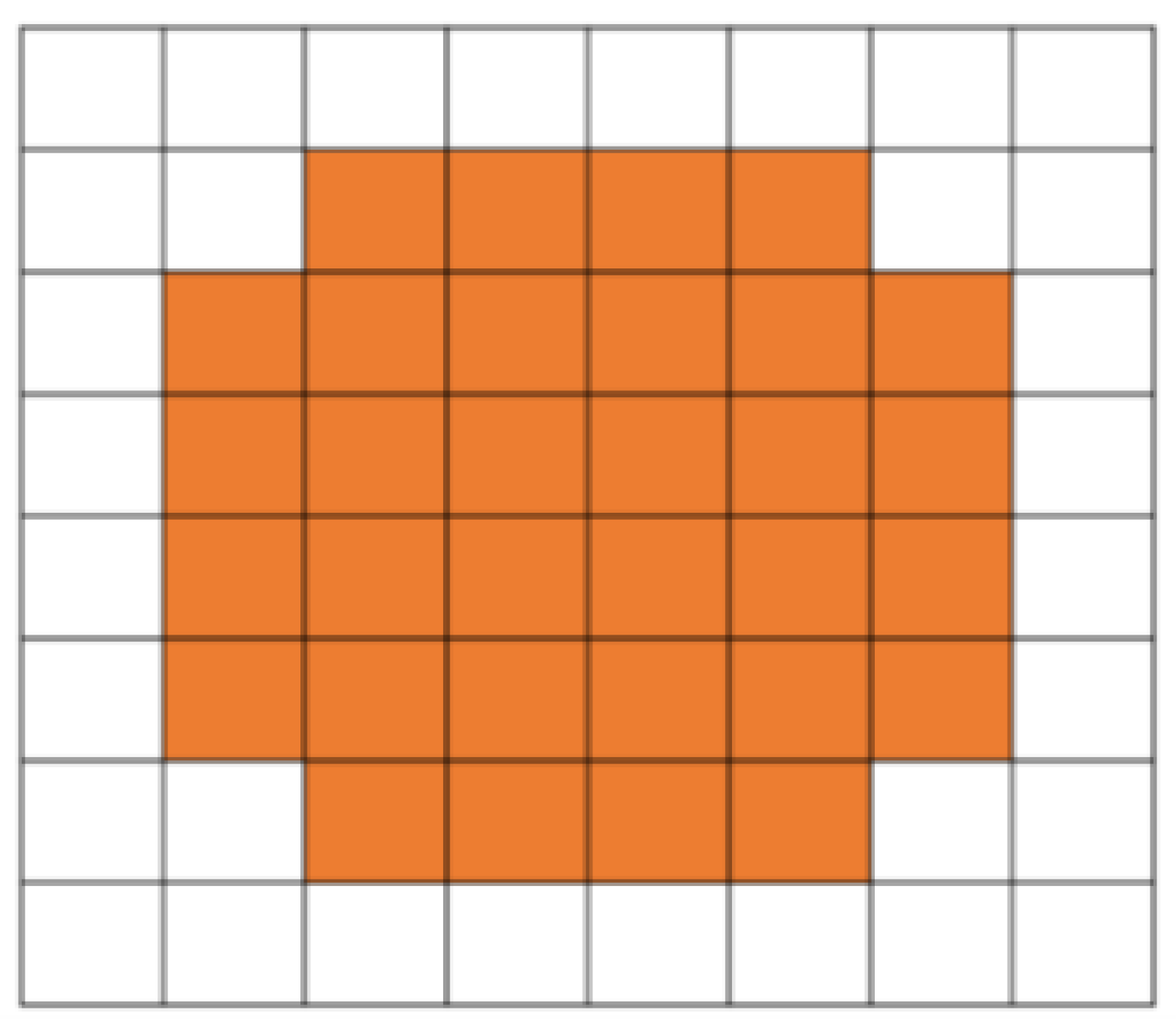
Figure 2.
Diagram of a typical LTSA antenna with key parameters, such as taper length (Lt), opening angle α, taper width (Wt), and feed slot width (Ws) clearly marked.
Figure 2.
Diagram of a typical LTSA antenna with key parameters, such as taper length (Lt), opening angle α, taper width (Wt), and feed slot width (Ws) clearly marked.
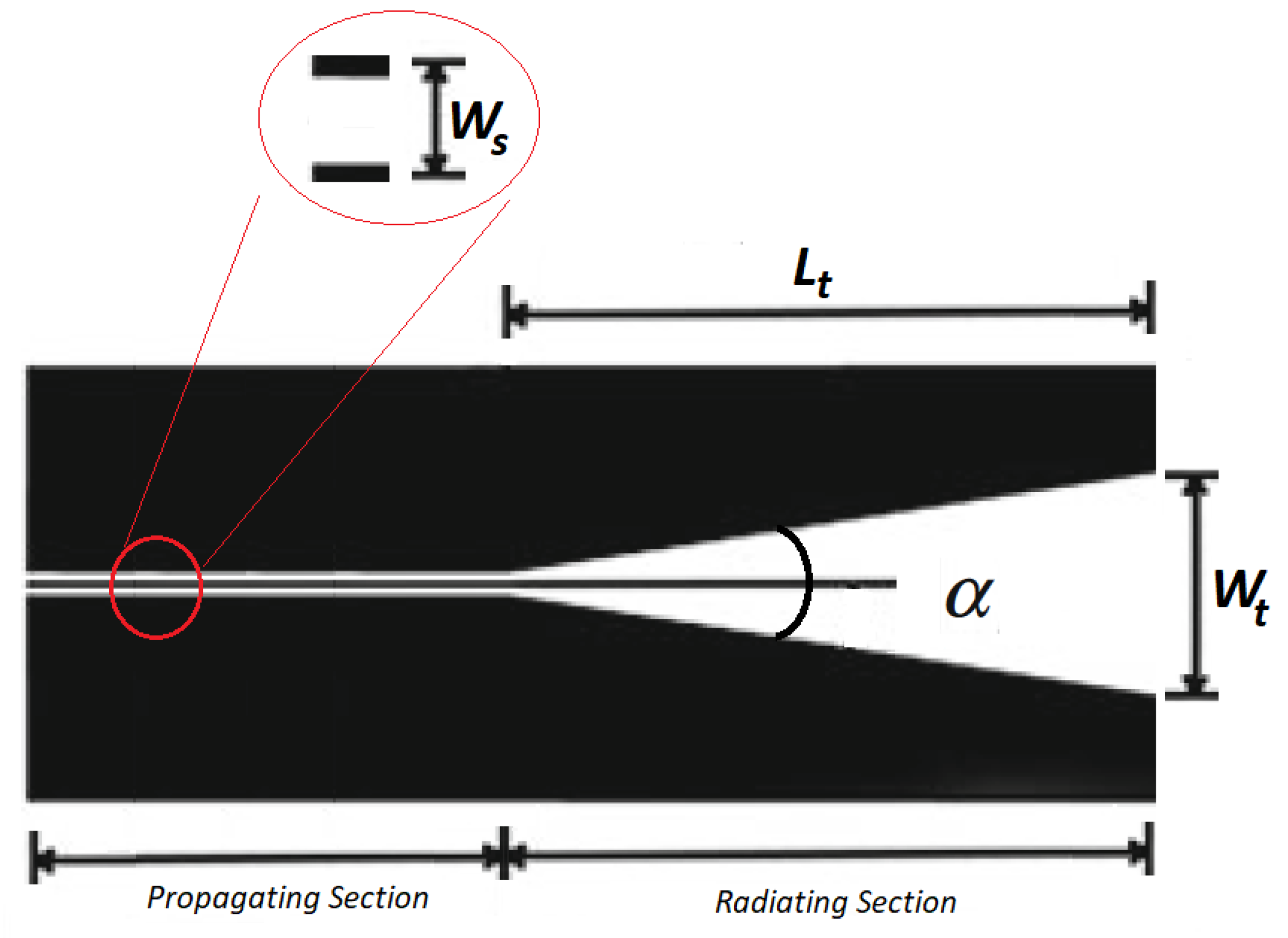
Figure 3.
Spacing between adjacent elements of the array.
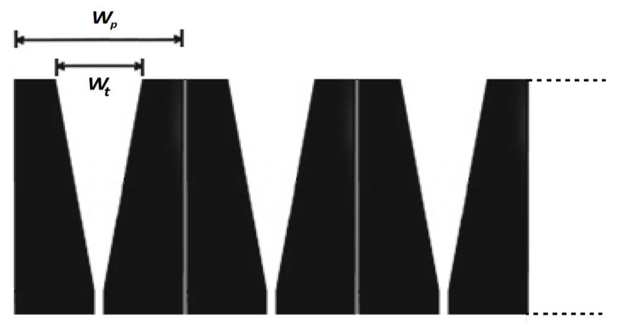
Figure 4.
(a) Unit Cell; (b) Parameters of the feeding network.
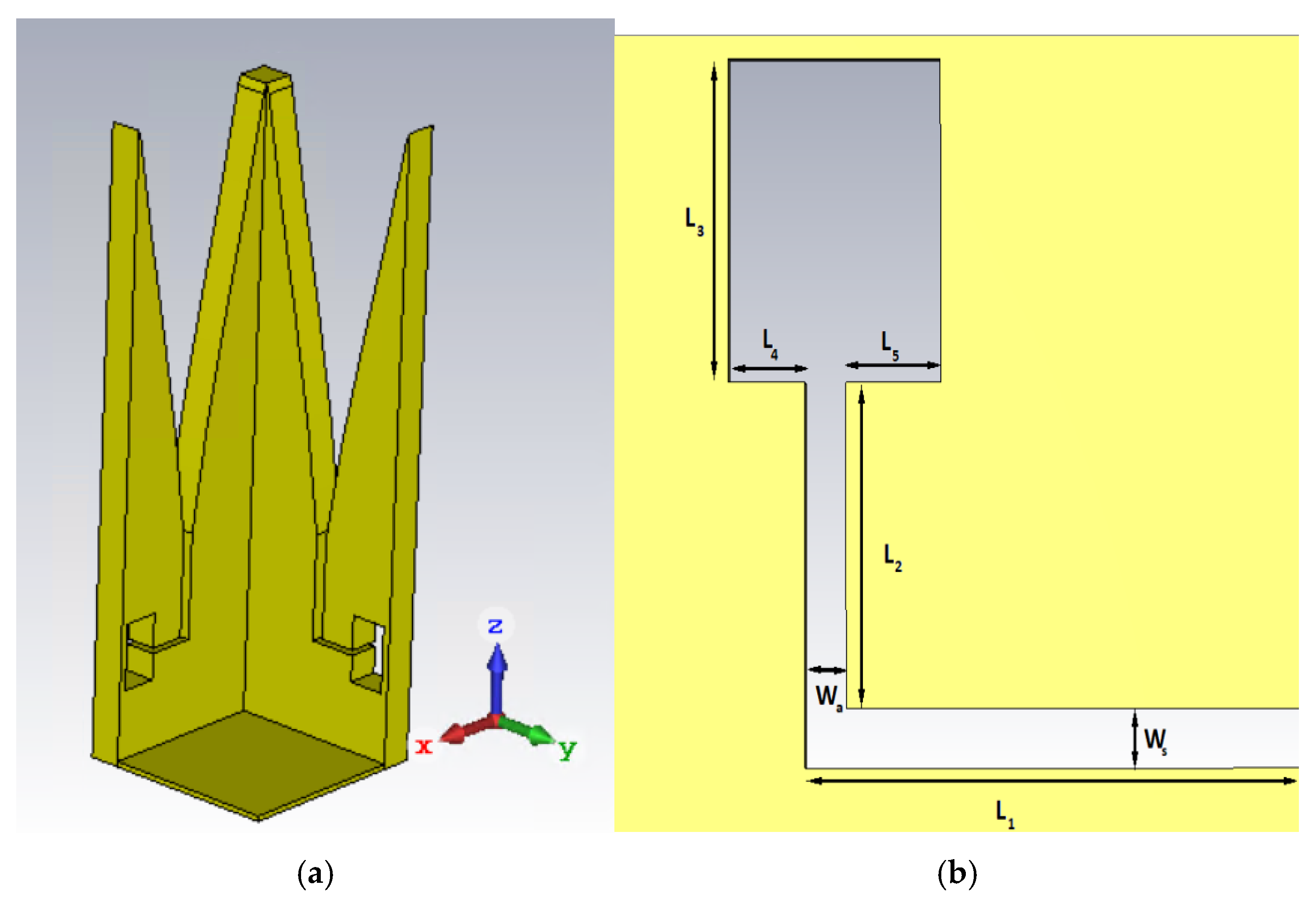
Figure 5.
(a) Implementation of the feeding probe integrated in the antenna.
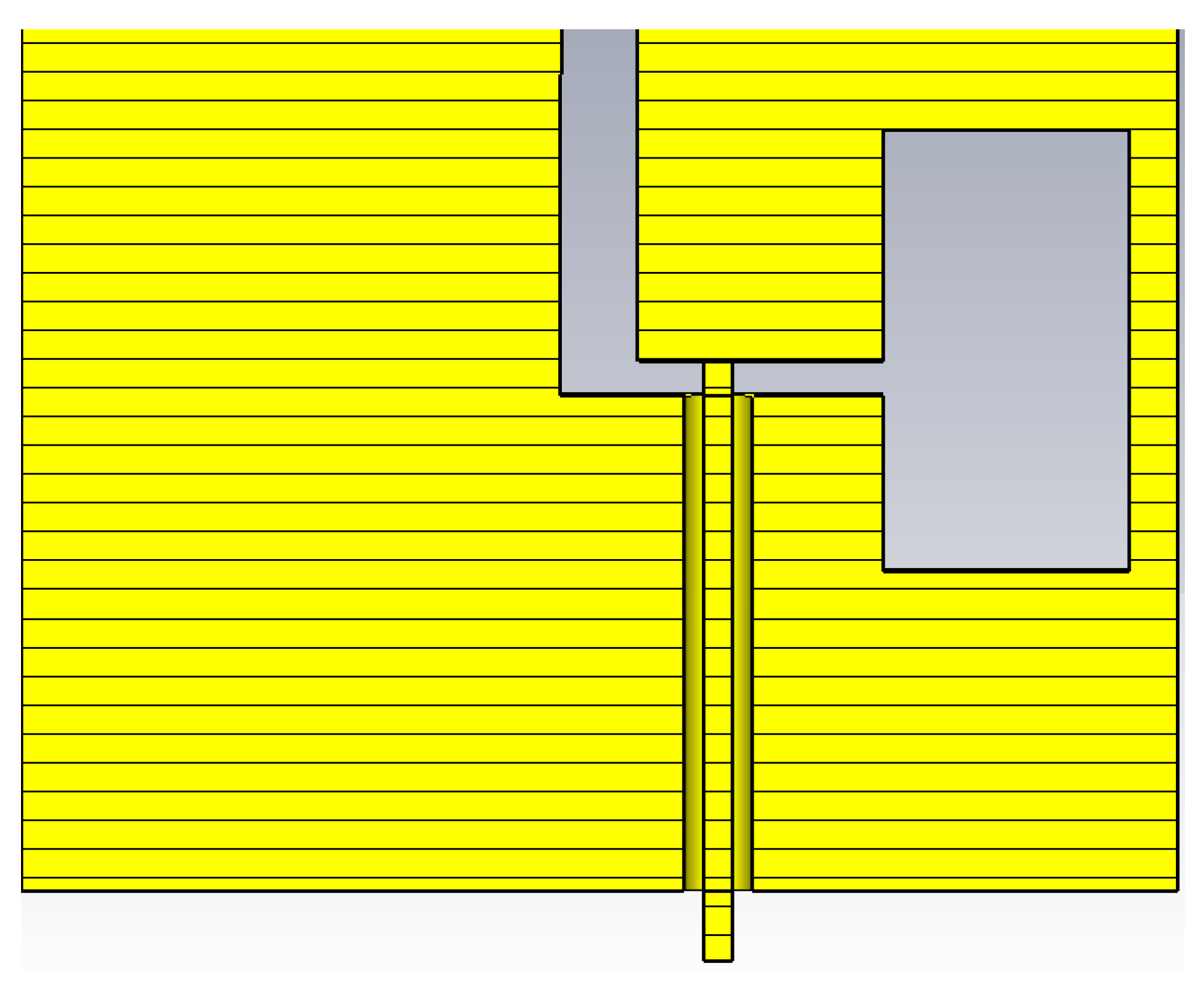
Figure 6.
a) 3D view of the 128 elements array; b) Antennas feeding scheme for edge taper adjustment (in red color the active zone): the antenna numbered with 93 and highlighted in green is the only one powered.
Figure 6.
a) 3D view of the 128 elements array; b) Antennas feeding scheme for edge taper adjustment (in red color the active zone): the antenna numbered with 93 and highlighted in green is the only one powered.
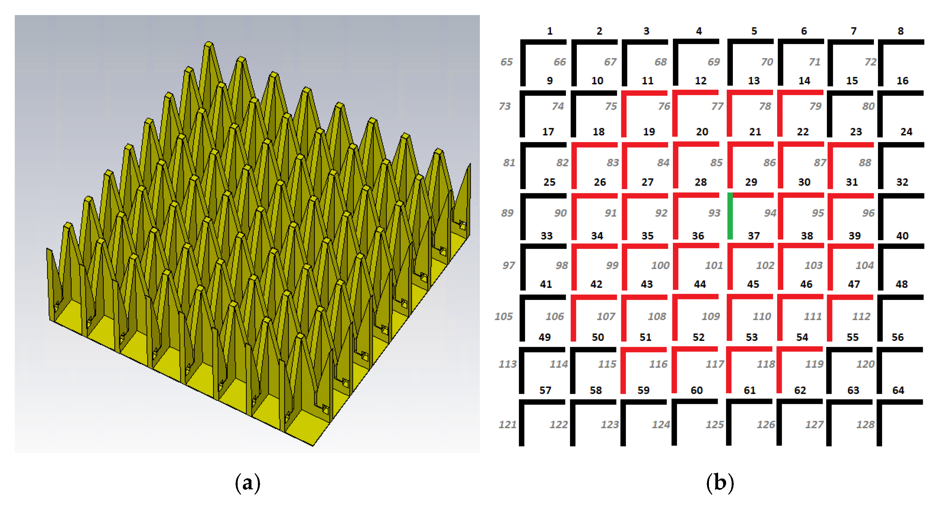
Figure 7.
H-Plane 5 dB edge taper: variation of taper length Lt.
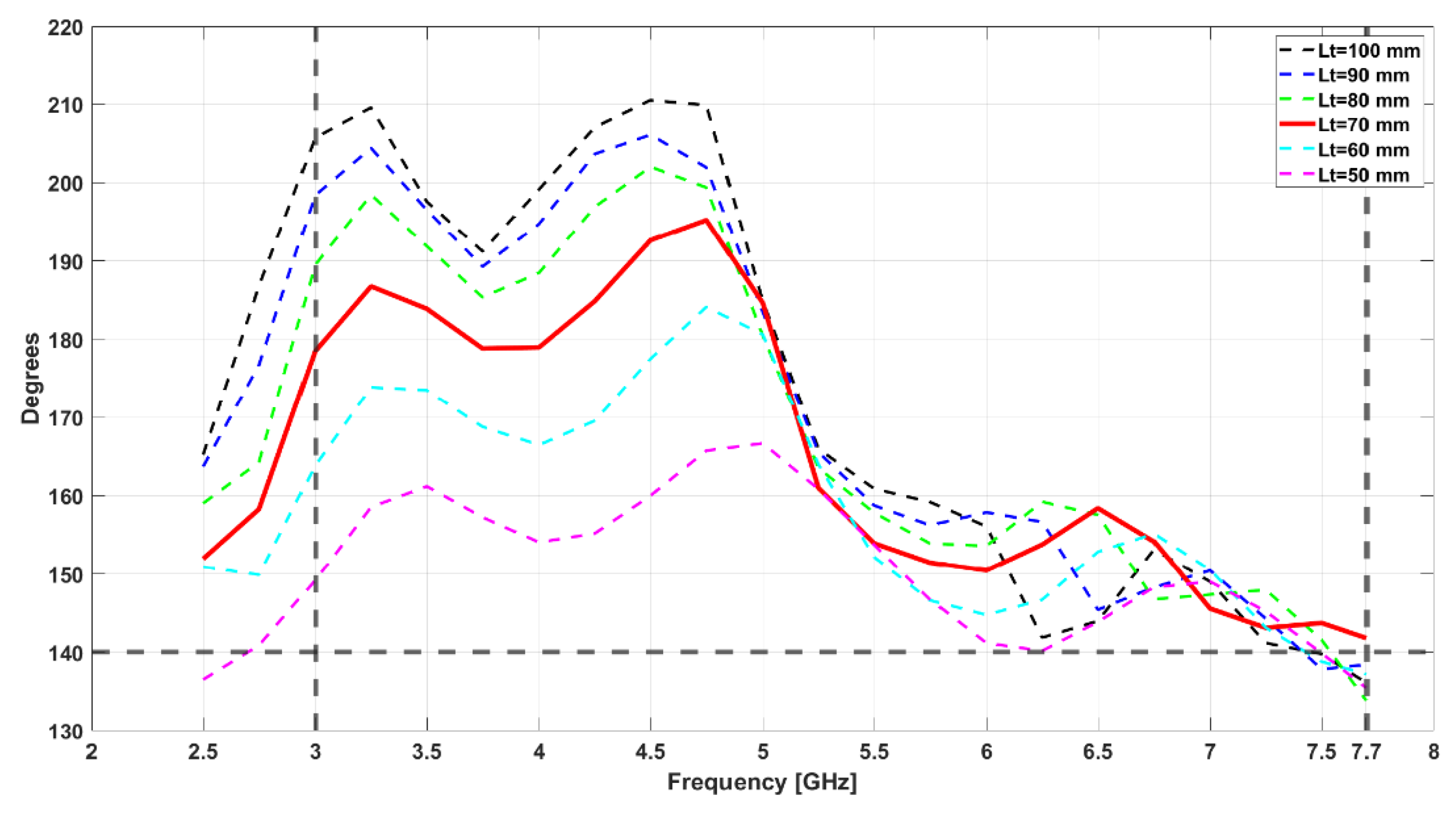
Figure 8.
H-Plane 5 dB edge taper: variation of taper length Lt.
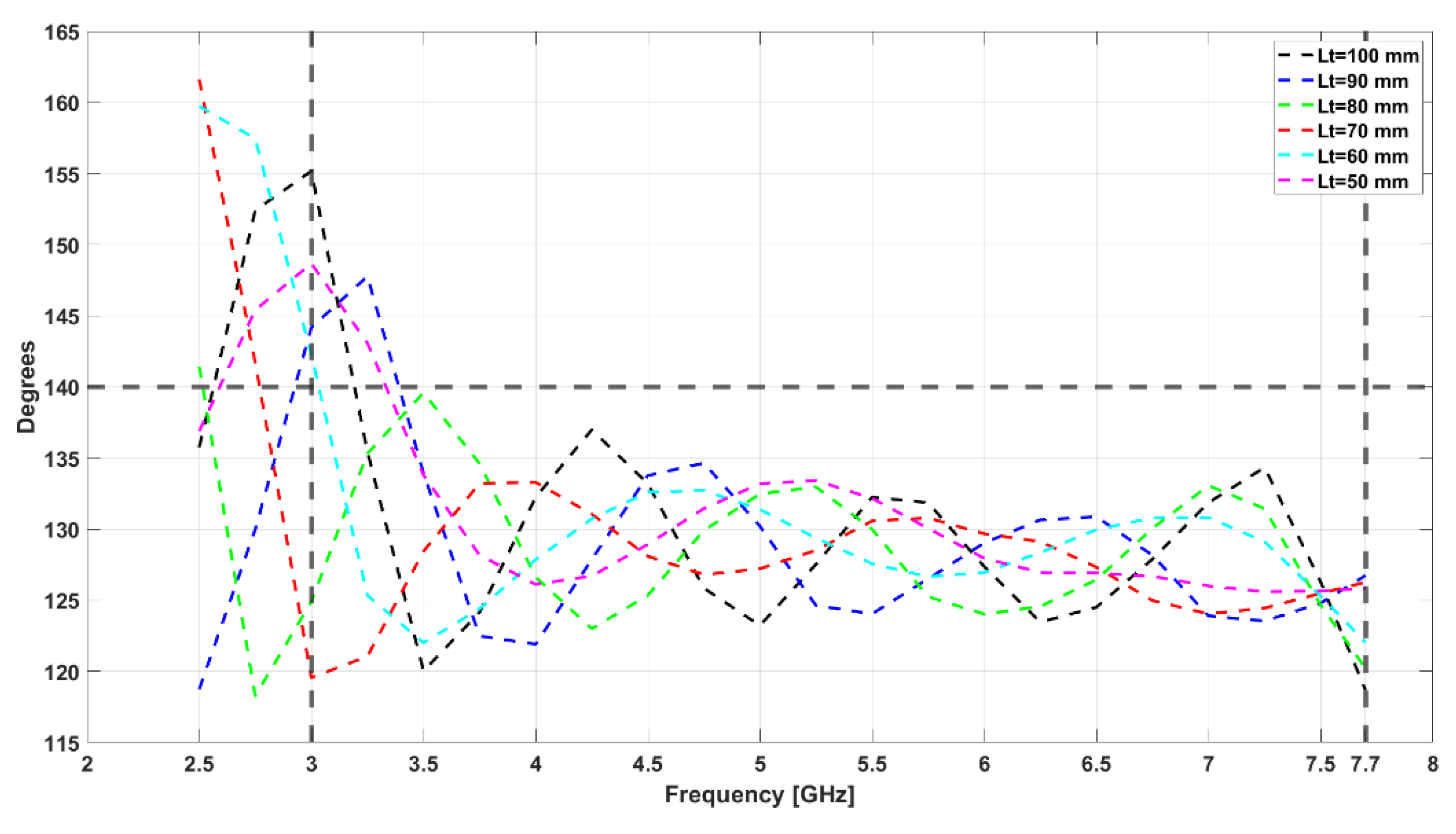
Figure 9.
Single LTSA H-Plane normalized radiated field.
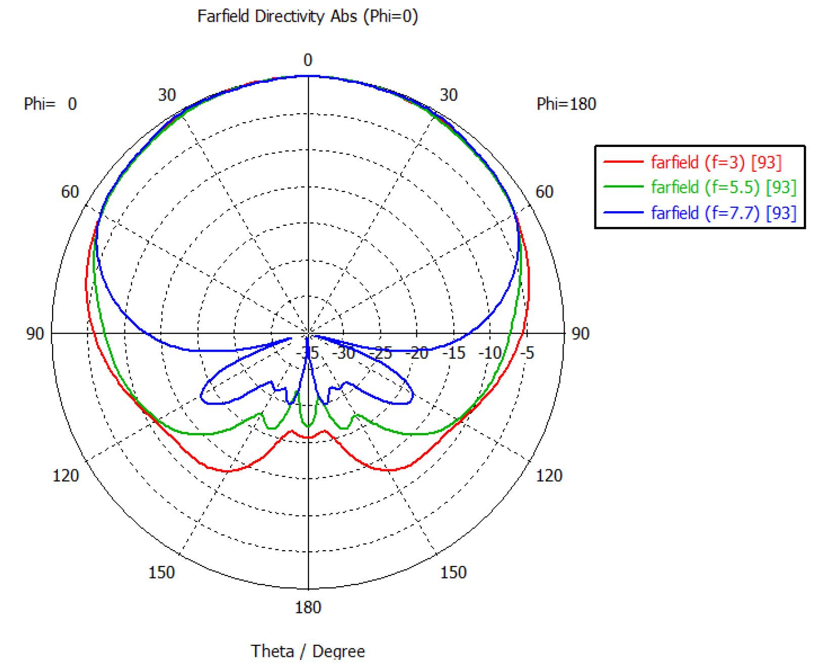
Figure 10.
Single LTSA E-Plane normalized radiated field.
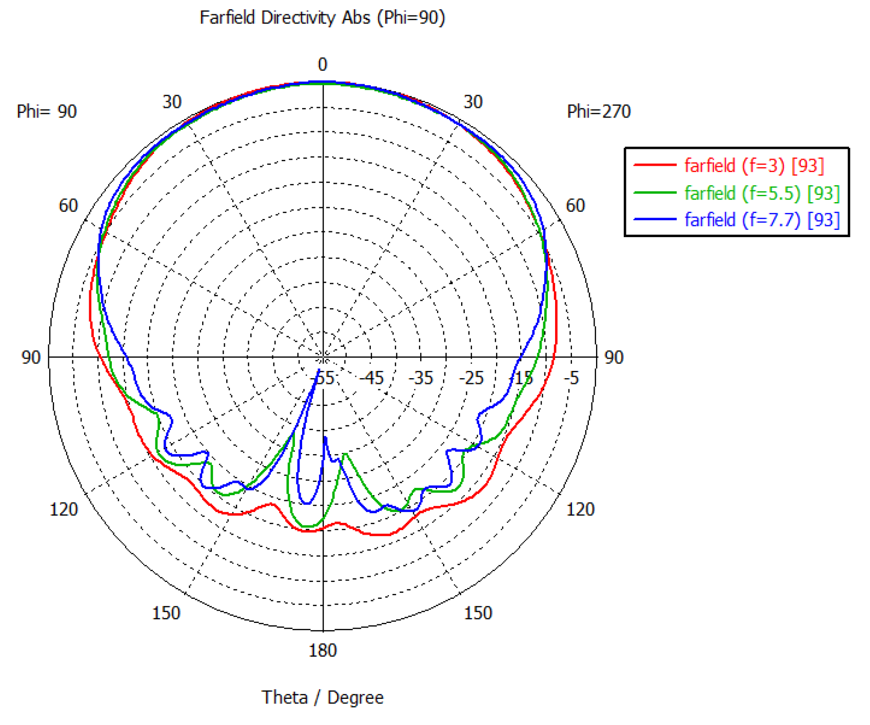
Figure 11.
S-parameters of the dual polarized unit cell.
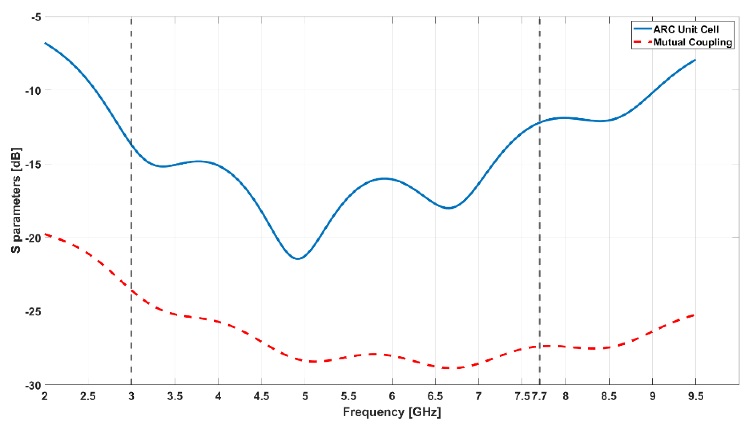
Figure 12.
Finite array model with additional boundary elements.
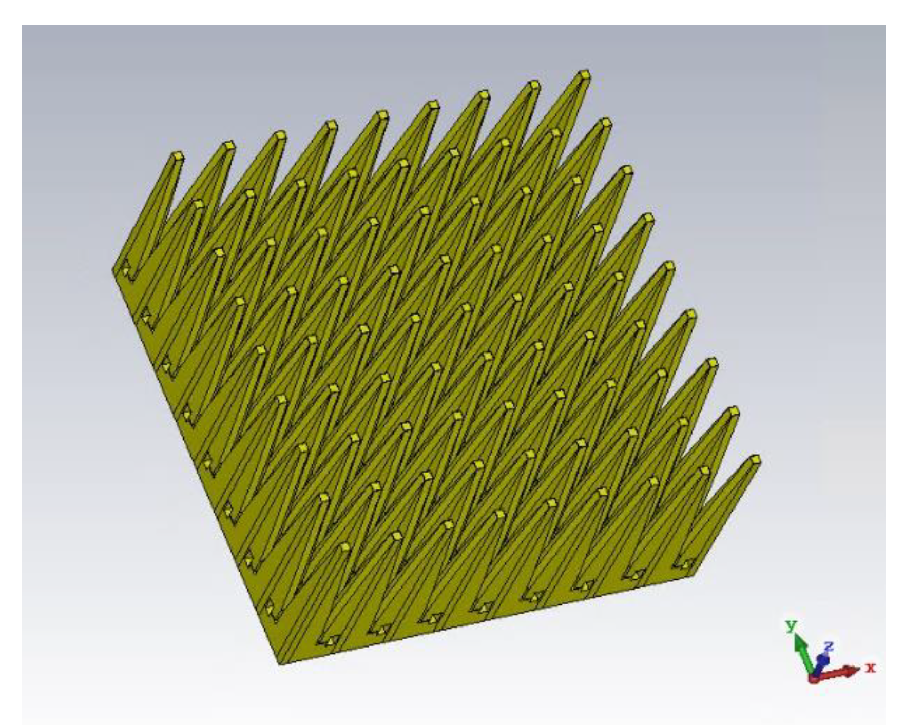
Figure 13.
Comparison between the ARCs of the single antenna of unit cell and the antenna labelled with number 93 in the finite array.
Figure 13.
Comparison between the ARCs of the single antenna of unit cell and the antenna labelled with number 93 in the finite array.
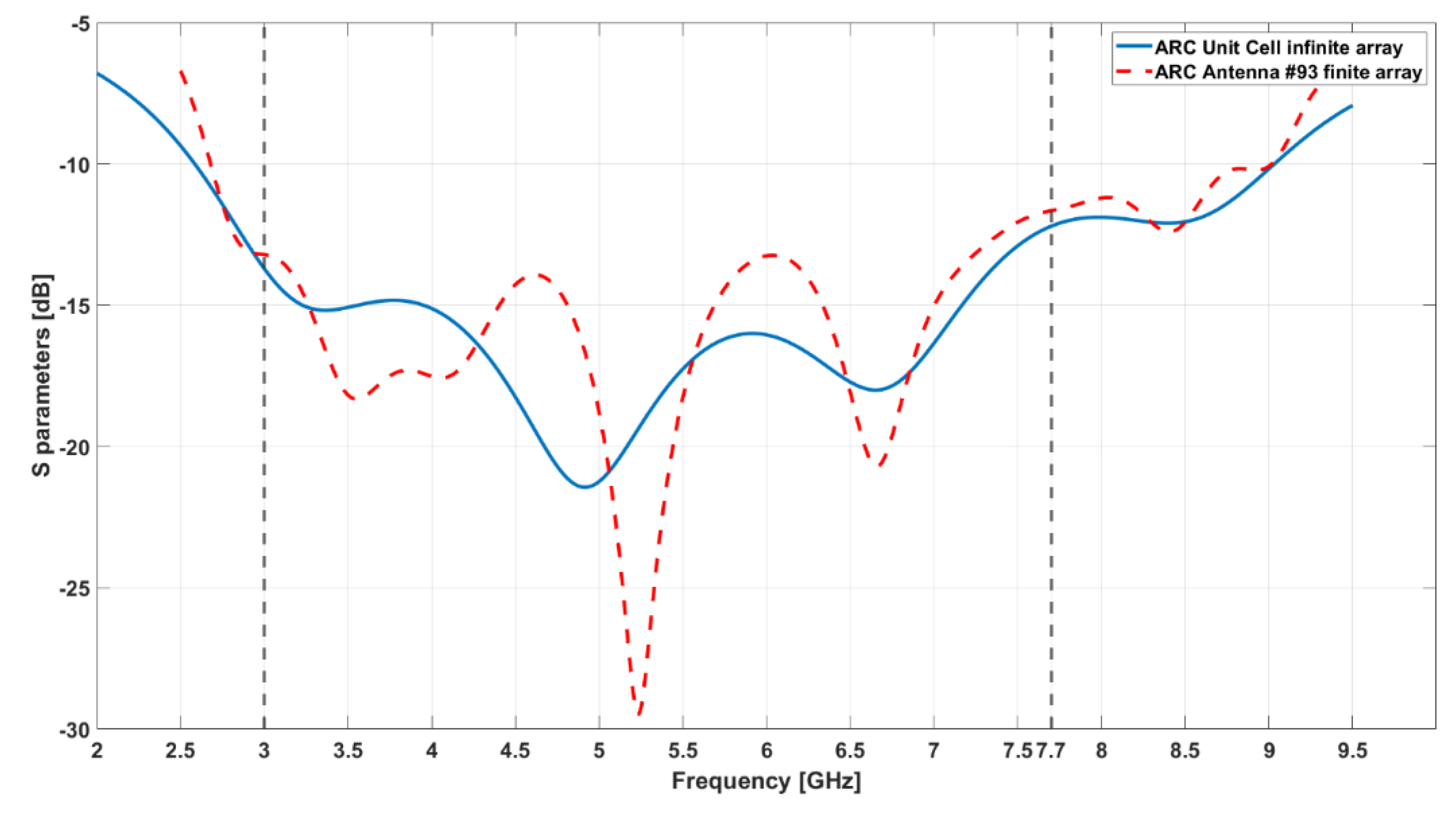

Table 1.
Performance comparison.
| Reference | Frequency band [GHz] | Single element | Single element pitch [mm] | Single element length [mm] | Arrayelements |
|---|---|---|---|---|---|
| This work | 3-7.7 | LTSA | 19.48 | 87 | 144 |
| [10] | 4-8 | ETSA | 21 | 77 | 220 |
| [6] | 3-6 | ETSA | 50 | 116 | 320 |
| [7] | 2.8-5.18 | ETSA | 28.8 | 53.6 | 140 |
| [25] | 2.5-4 | ETSA | 37 | 125 | 40 |
| [39] | 4-8 | Bowtie | 25 | 18.75 | 24 |
Disclaimer/Publisher’s Note: The statements, opinions and data contained in all publications are solely those of the individual author(s) and contributor(s) and not of MDPI and/or the editor(s). MDPI and/or the editor(s) disclaim responsibility for any injury to people or property resulting from any ideas, methods, instructions or products referred to in the content. |
© 2024 by the authors. Licensee MDPI, Basel, Switzerland. This article is an open access article distributed under the terms and conditions of the Creative Commons Attribution (CC BY) license (http://creativecommons.org/licenses/by/4.0/).
Copyright: This open access article is published under a Creative Commons CC BY 4.0 license, which permit the free download, distribution, and reuse, provided that the author and preprint are cited in any reuse.


