1. Introduction
Natural biological materials serve as both structural and functional components. The study of the relationship between the structure and properties of natural biomaterials is the basis of the development of biomimetic structure and function.
[1] The characteristics of the wing structure of flying insects have inspired researchers to develop biomimetic designs. The understanding of the growth process of structures in nature and their functions can guide researchers to simulate and produce bionic structures with good mechanical properties
[2,3,4]. Insect wings are intricate marvels of evolution and bioengineering, serving as complex mechanical structures. They are light, strong, durable and flexible, thanks to "veining," thickened, pillar-like structures embedded in the surface of the wing. The density and spatial arrangement of veins vary widely between insects, and they serve many functions: increasing wing strength, preventing crack growth, forming corrugated vertices, conducting fluids, supporting structures, and helping to maintain structural characteristics when deformation occurs under aerodynamic action
[5,6,7,8,9].
Woottond
[10] et al. summarize the latest work in insect wing structure modeling and show how these studies have progressed from simple conceptual models of wing structure to analytical and numerical methods. Some researchers have used finite element models to build insect wing models
[11,12,13,14]. A limitation of these methods is the necessity for detailed information on the venous and membrane scanning structures of the entire model, along with mechanical properties, for building finite element models. In this paper, we use the generation process of branch structure to simulate the main veins of the forewings, combine the polygon grid in the Voronoi grid to simulate the structure, and then use the method similar to origami to simulate the fold of the dragonfly forewings, and realize the generation process of the dragonfly wing three-dimensional structure by the algorithm, which provides a new method for the design optimization of three-dimensional bionic structure. This method is applied to the design of the load-bearing structures, and the bionic structures obtained have excellent mechanical properties.
The load is distributed between the dragonfly's veins and wing membrane, comprising a large number of irregular grid structures that only represent 1-2% of the total weight. This highly optimized stress structure is depicted in
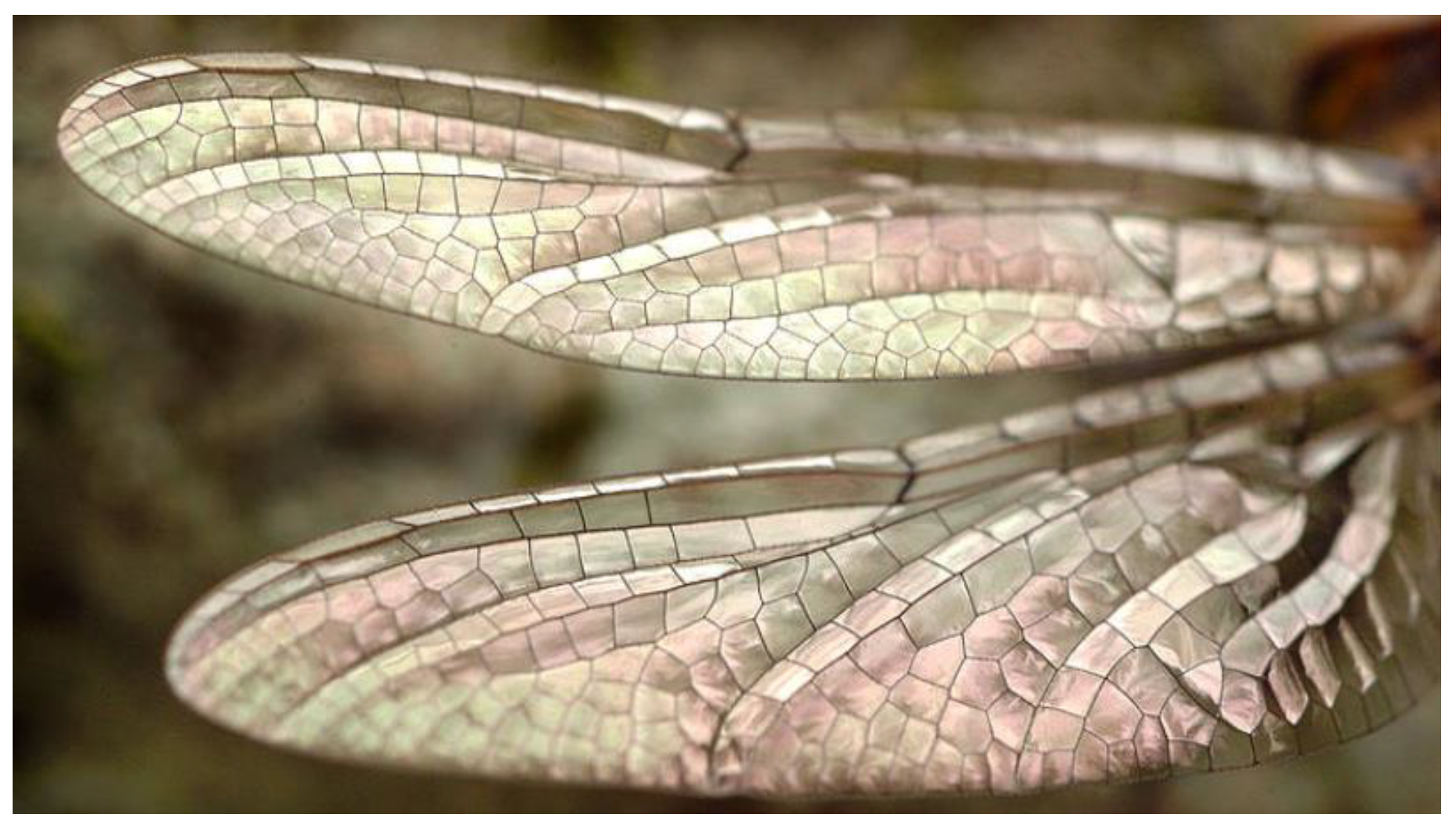
Figure 1, illustrating the connection between the front and rear wings of the dragonfly via a main vein and a grid structure. Despite comprising less than 2% of the total weight, dragonfly wings exhibit stability and high carrying capacity during various flight maneuvers such as flapping, gliding, and hovering.
[15,16] Dragonfly wings consist of a thin film supported by a hollow tubular system of wing veins, which are cross-connected to form closed "cells". This gives rise to the characteristics of the whole structure
[17,18]. The microstructure of dragonfly wings is relatively complex. It has been found that wing ripple is very important for the stability of ultralight wings. It can deal with the straddling bending force and mechanical wear experienced by the wings during flapping. Flexible cross-vein connections, variation in the size of the vein, and sandwich structure are all important features.
[19,20,21,22] The fold structure shown in
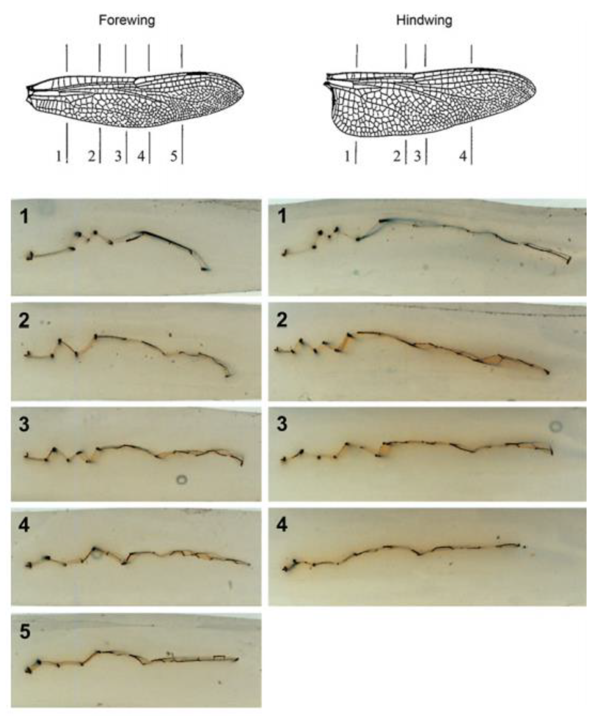
Figure 2 consists of symmetrical waves at regular intervals along the chord, enhancing the wings' carrying capacity significantly. Overall, the dragonfly wing structure is highly efficient. Thus, this paper takes dragonfly wings as the research object and simulates the structural form of dragonfly wings using the parametric modeling method to establish a high-performance bionic three-dimensional grid structure.
3. Generate a 3D Model of Dragonfly Wing
The process of generating a dragonfly fold grid structure by using the above method is shown in
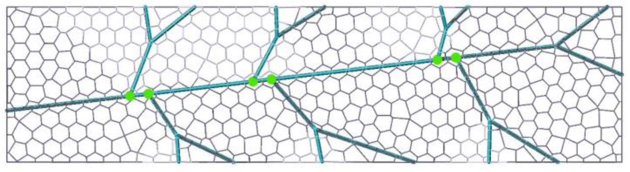
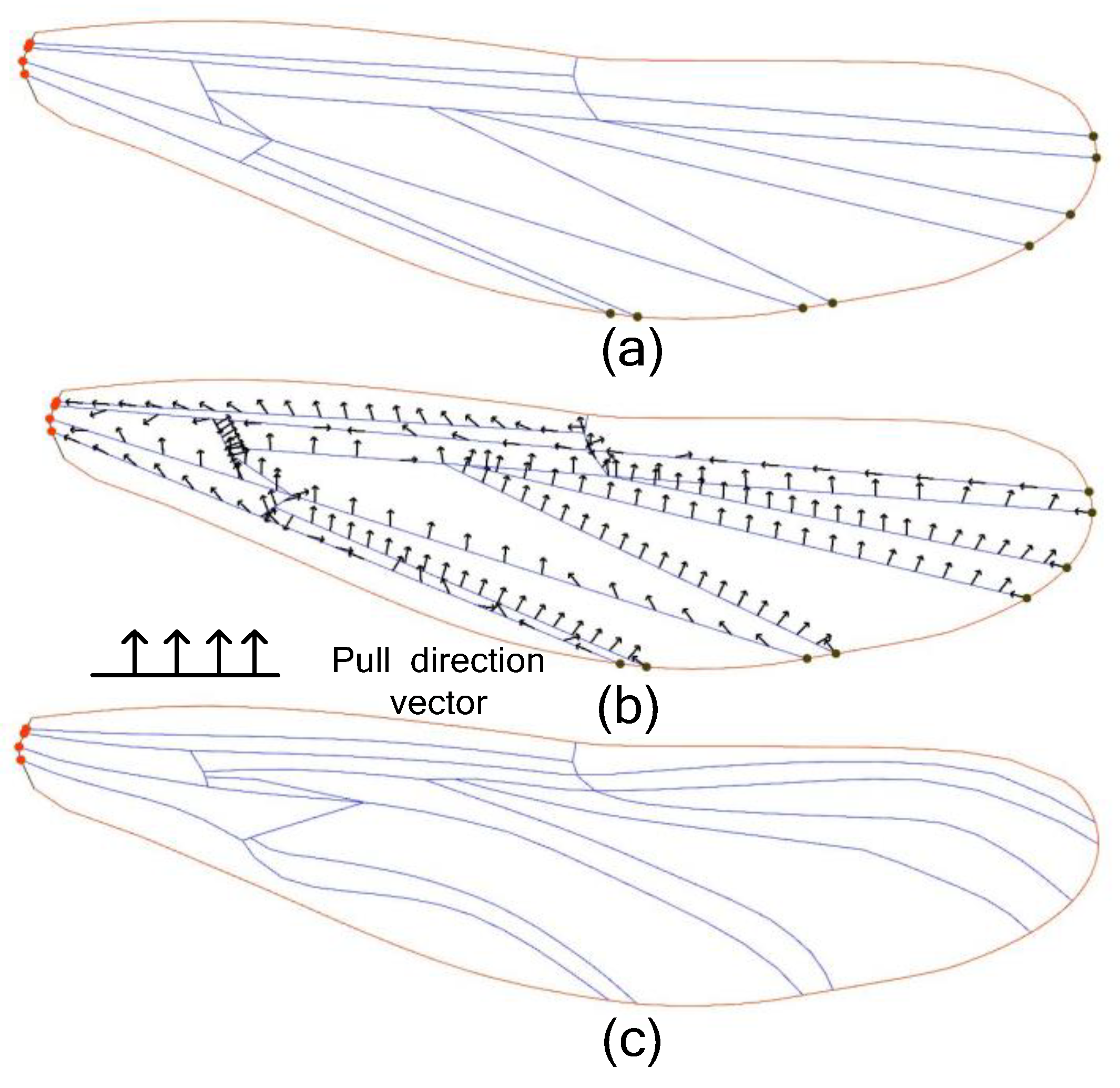
Figure 11. Since the real dragonfly vein is a curve, it is necessary to turn the branch line into a curve. The transformation method is to regard the branch line as an elastic line with fixed end points, define a group of normal phase vectors on the branch line, and the curve will deform along these vectors. By adjusting the position and direction of the normal phase vector, the curve will gradually approach the shape of the real wing vein curve.
The dragonfly wings in
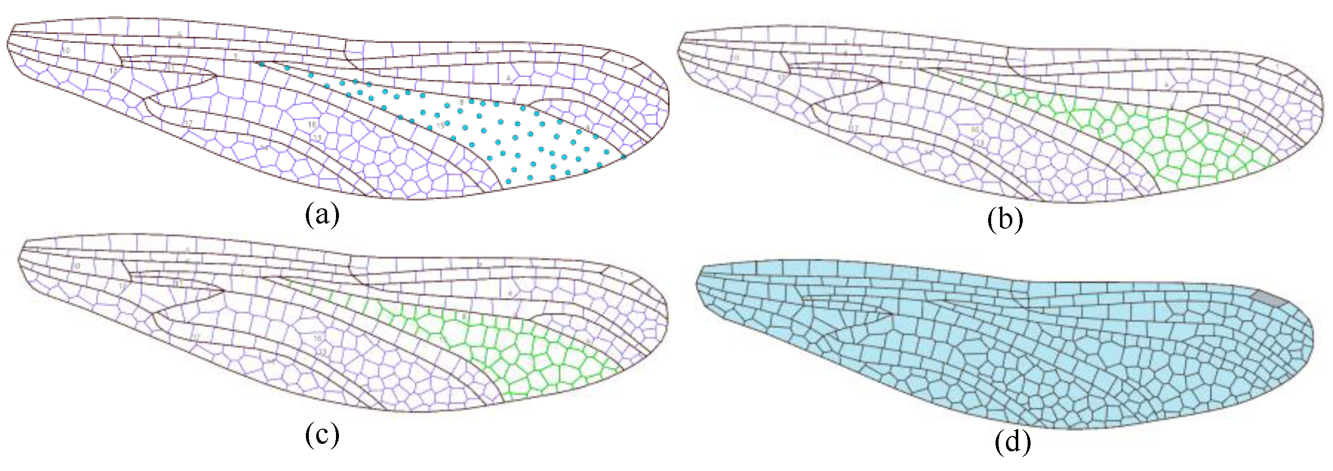
Figure 11c are divided into many different areas, and the centroid Voronoi grid is filled in these areas, as shown in
Figure 12. The finally generated two-dimensional wing grid structure showed in
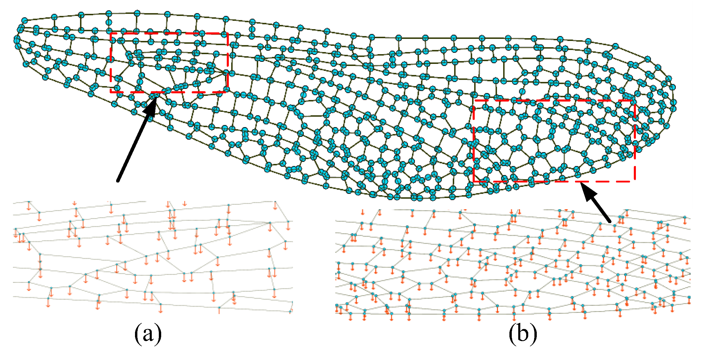
Figure 12(d). The whole structure contains 354 polygonal grid units, among which triangles account for 1.4%, quadrilateral for 12.15%, pentagonal for 30.23%, and 56.21%. During the generation of the dragonfly wing grid structure fold, the average load qave obtained from equation 3 is added to the node, as shown in
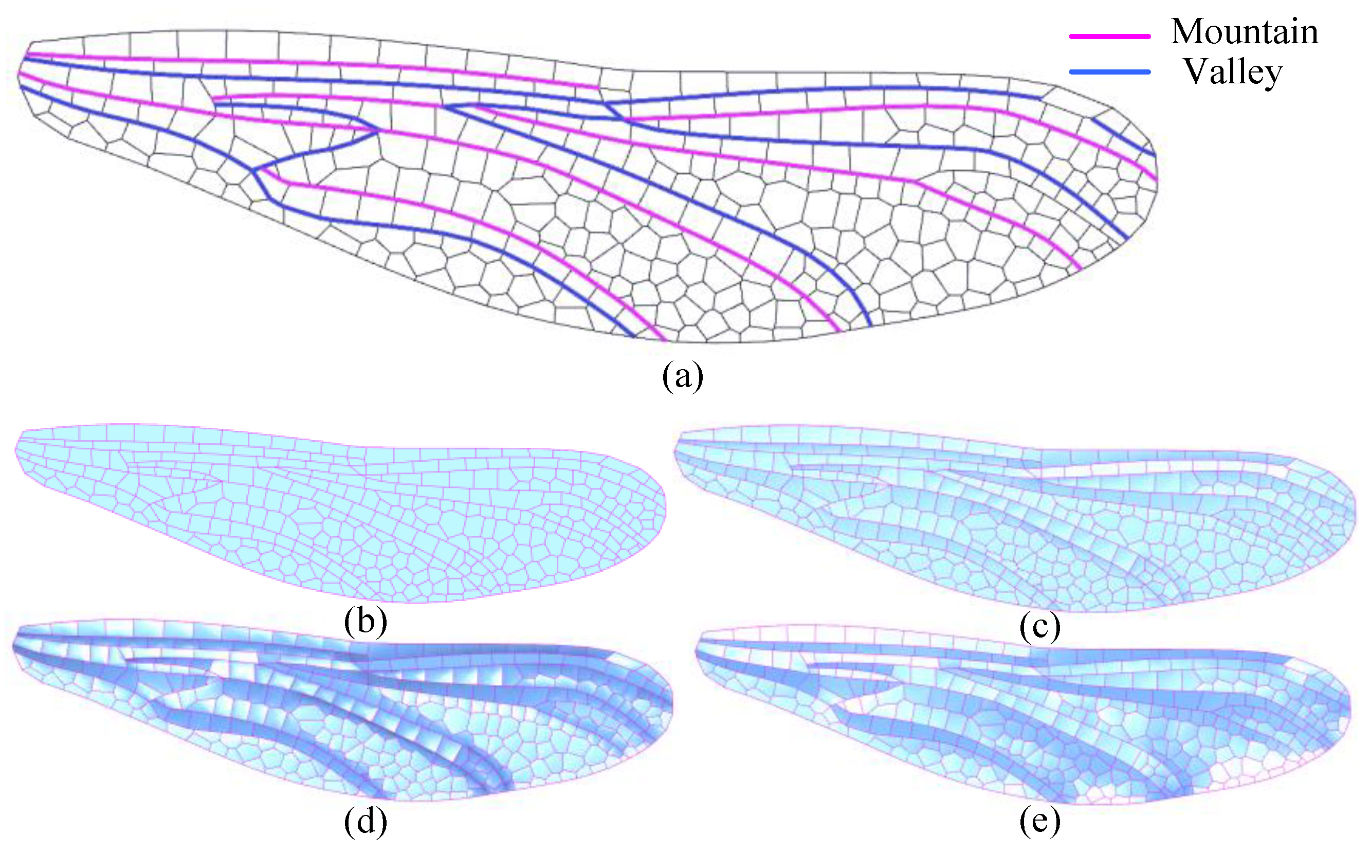
Figure 13. The forewing two-dimensional model generated in
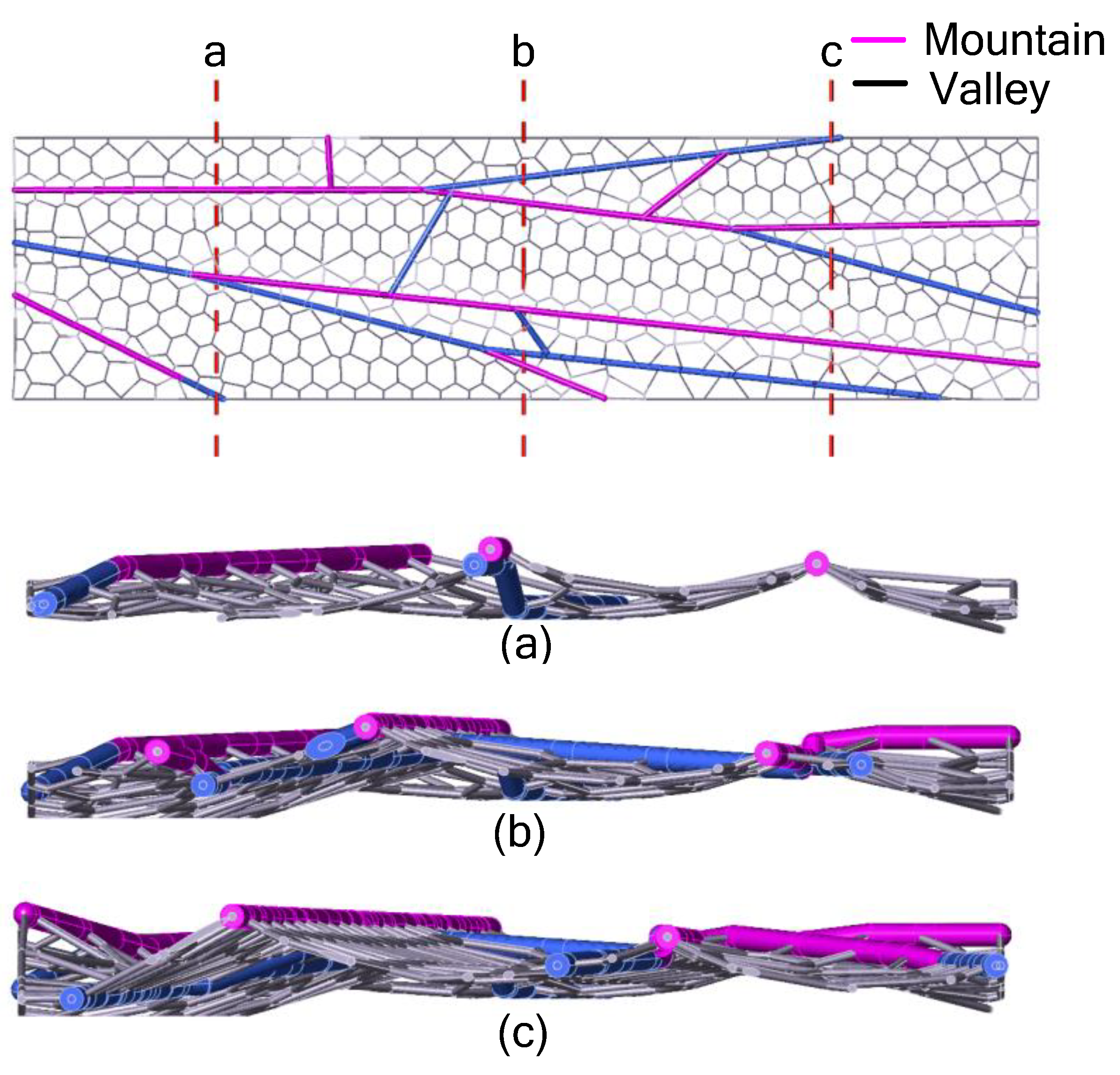
Figure 14 has 13 main veins, which are divided into 6 Mountain lines (M) and 7 Valley lines (V). According to the divided M-V folding lines, fold structure is generated, as shown in
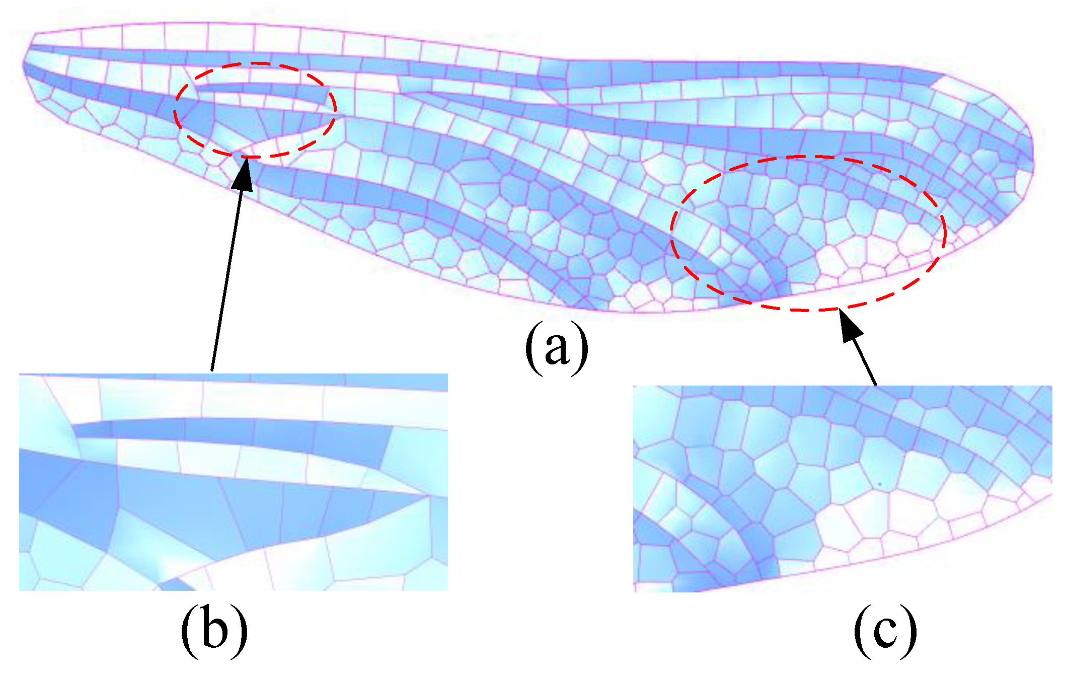
Figure 14(e). After the definition of folding lines, the forewing model prepares to generate fold structure. The folding process continues until the entire grid structure reaches a stable state, and the grid structure in this state is the final forewing three-dimensional model, as shown in
Figure 15a. Folding structures in different regions have different forms. There is a large amount of filling grid between two folding lines in
Figure 15c, so the fold change in this area is not as obvious as that in 15b.
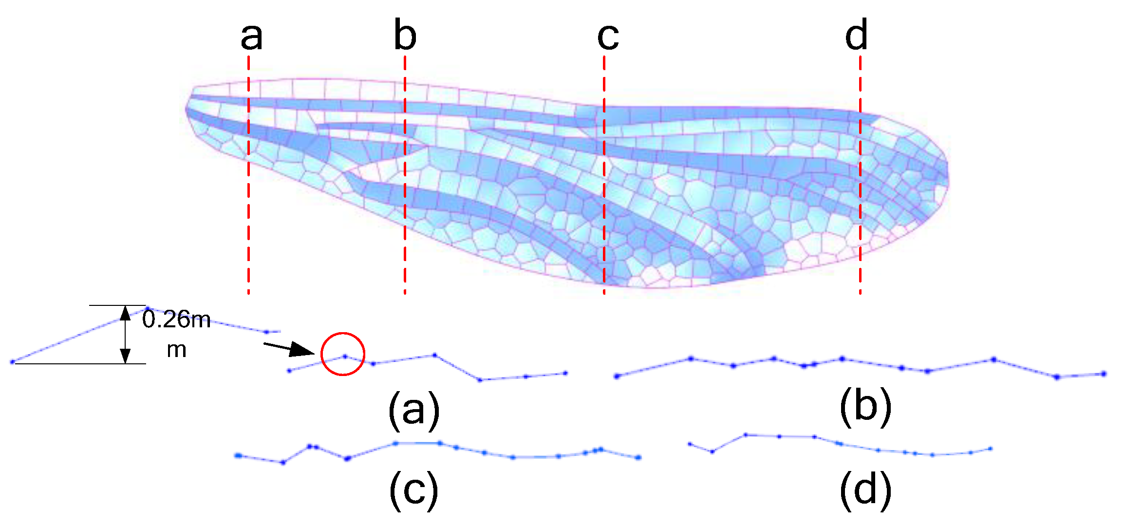
Figure 16 shows the cross section of the forewing 3D model. The simpler the grid units on both sides of the fold line, the more obvious the fold is; otherwise, the grid structure is more flattened. The three-dimensional forewing model generated in this paper for finite element analysis is shown in
Figure 17. The weight of the dragonfly is
m=865.3mg, the wing area is
Af=713.32mm
2, and the average load on the wing surface is
qave,
.
4. Structural Design Application
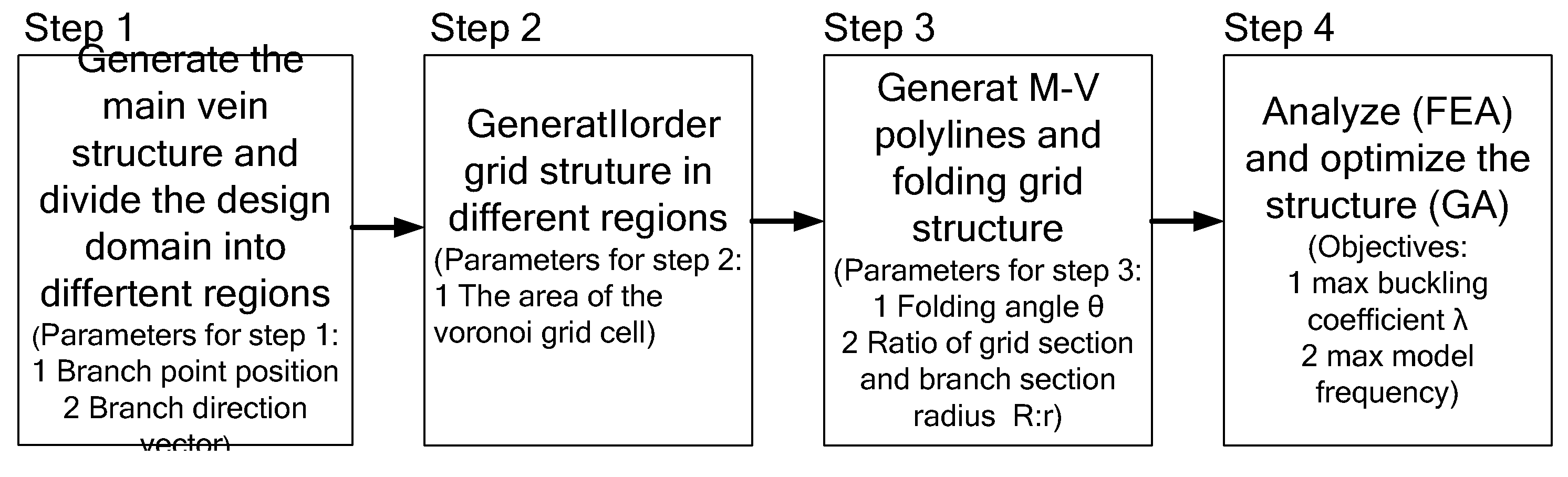
Dragonfly wing structure is an efficient structure form, so this paper explores the combination of the genetic algorithm (GA) and the above simulation dragonfly wing 3D grid structure generation process applied to the bionic optimization design of the loaded structure. The whole process is shown in
Figure 18. Step 1: Branch structure is generated by taking the location of branch points and the direction vector of branches as parameters; Step 2: centroid Voronoi grid is generated by taking the area of grid units as parameters; Step 3: Folding angle θ and ratio of the section radius of the branch structure to the section radius of Voronoi grid R: r is used as the parameter to generate the folding grid structure. Step 4: Analyze and optimize the structure.
Table 1 shows the basic parameters of the material: elastic modulus (E1, E2, E3), shear modulus (G12, G13, G23) and Poisson's ratio (ν12, ν13).
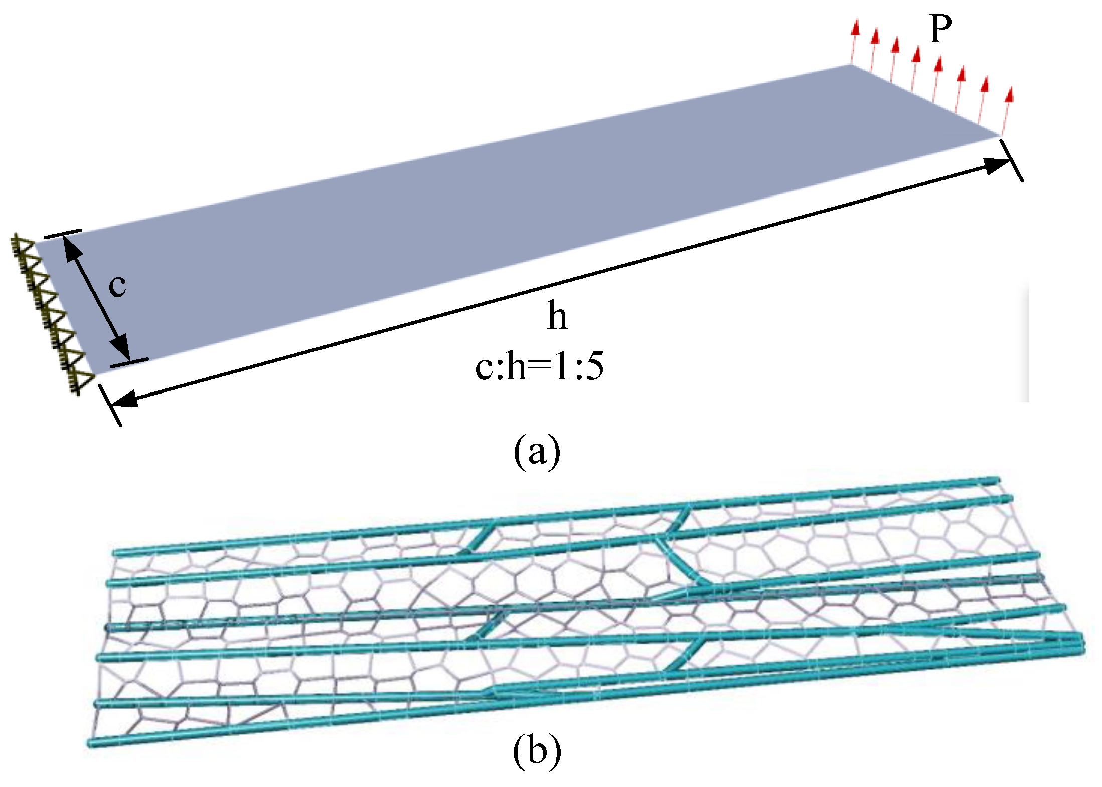
The load and support conditions of the two-dimensional plane design domain are shown in
Figure 19(a), the aspect ratio of the domain c:h=1:5, and the load P=1.
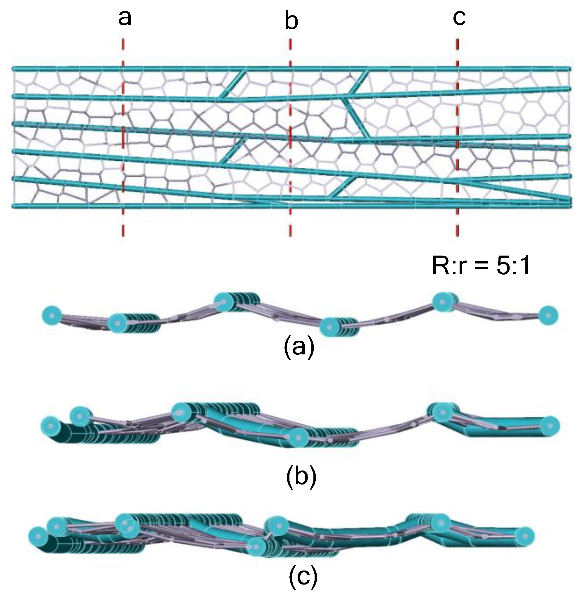
Figure 19(b) shows the optimized grid structure of the two-dimensional design domain, the folds in the structure are shown in
Figure 20, and the ratio of the section radius R of the branch structure to r of the filled grid is 5:1. As shown in
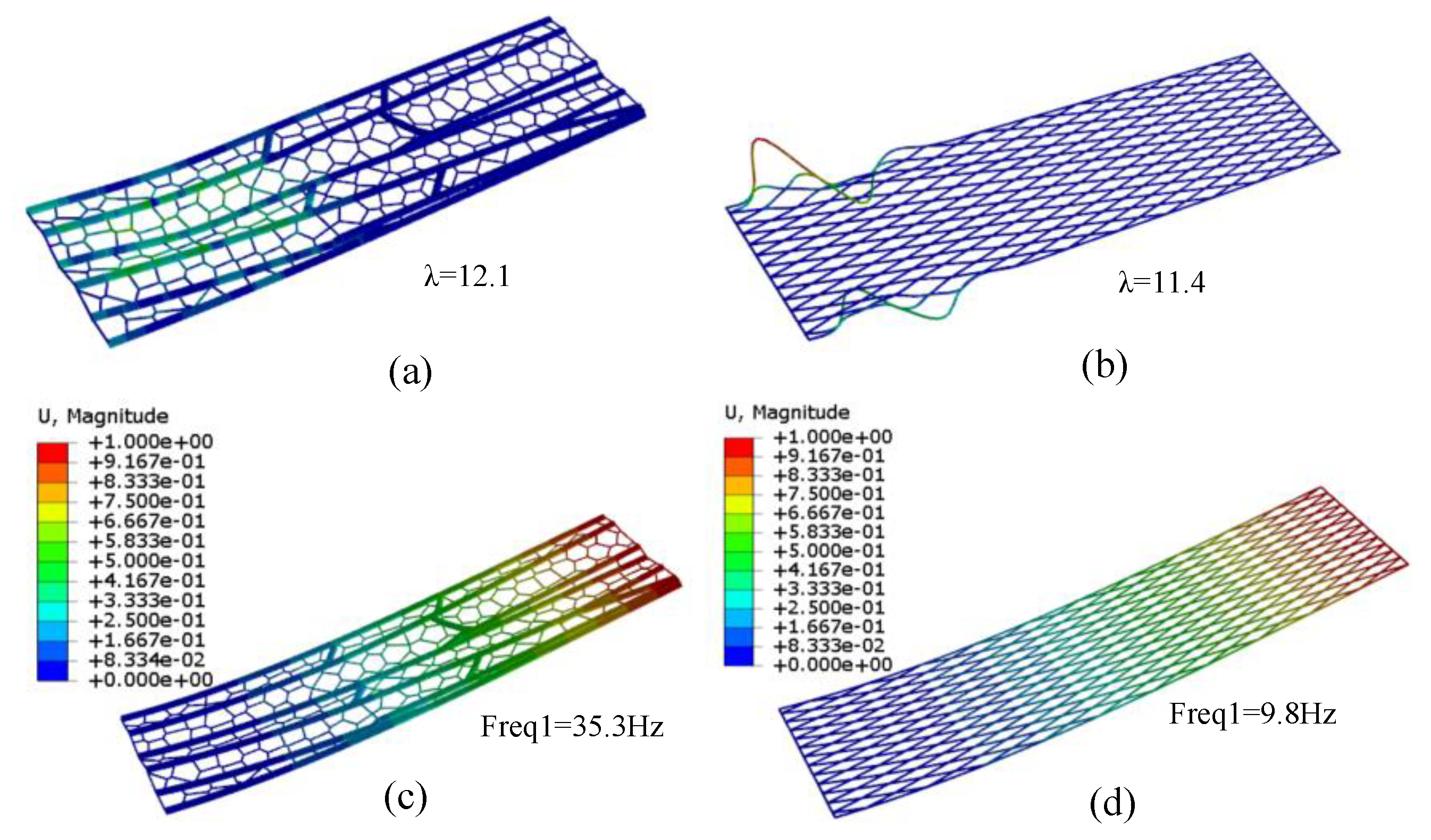
Figure 21, under the same load and support conditions, compared with the quadrilateral grid structure, the buckling load of the folded bionic dragonfly vein structure is 11% higher, and the buckling load is mainly borne by the branch structure. The filling grid structure can increase the first-order modal frequency of the whole structure by 2.6 times, which plays a similar effect to the flexible structure. The grid structure simulating dragonfly's wing has the effect of rigid and flexible coupling structure.
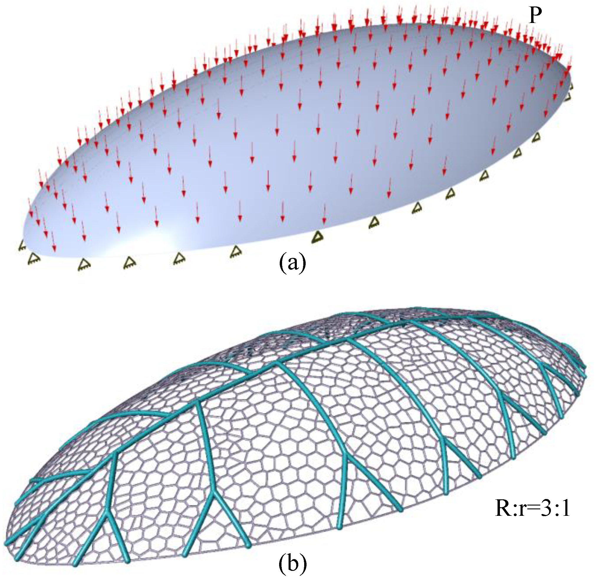
The load and support conditions of ellipsoidal domain under a distributed loading are show in
Figure 22 (a).
Figure 22(b) shows the optimized grid structure in the design domain of the ellipsoidal surface, and almost no folding. The ratio of section radius R of the branch structure to that of the filled grid is 3:1. As shown in
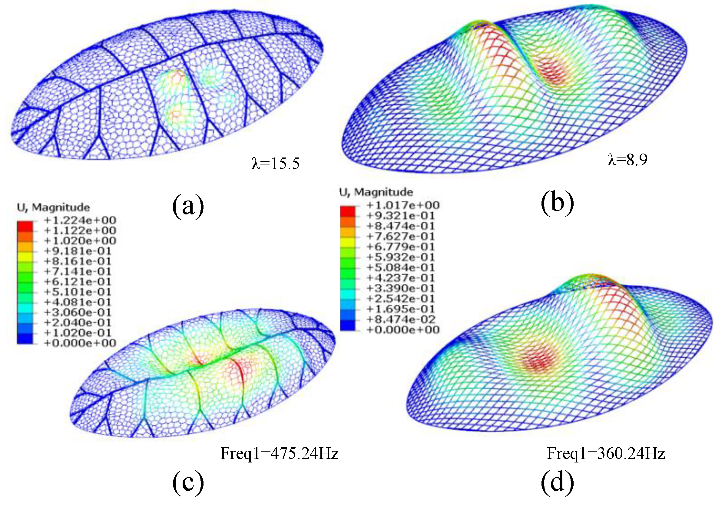
Figure 23, under the same load and support conditions, compared with the quadrilateral grid structure, the buckling load of the grid structure biomimetic dragonfly's wing vein increases by 1.7 times, and the first-order modal frequency of the structure increases by 1.3 times.
Different from the plane design domain, the beam elements obtained in the elliptic design domain mainly bear axial loads, and from the obtained grid structure, it can be seen that there are no obvious folds like the grid structure mainly bearing bending loads as shown in
Figure 22. Therefore, whether the grid structure needs to be strengthened by folding is related to the angle between the axial direction of the beam element and the load direction. In general, by combining the branching structure, the Voronoi grid and folding method can simulate the three-dimensional fold structure of the dragonfly wing. When the structure mainly suffers from torsion and bending deformation, the structure will improve its resistance to torsion and bending by generating fold structure.
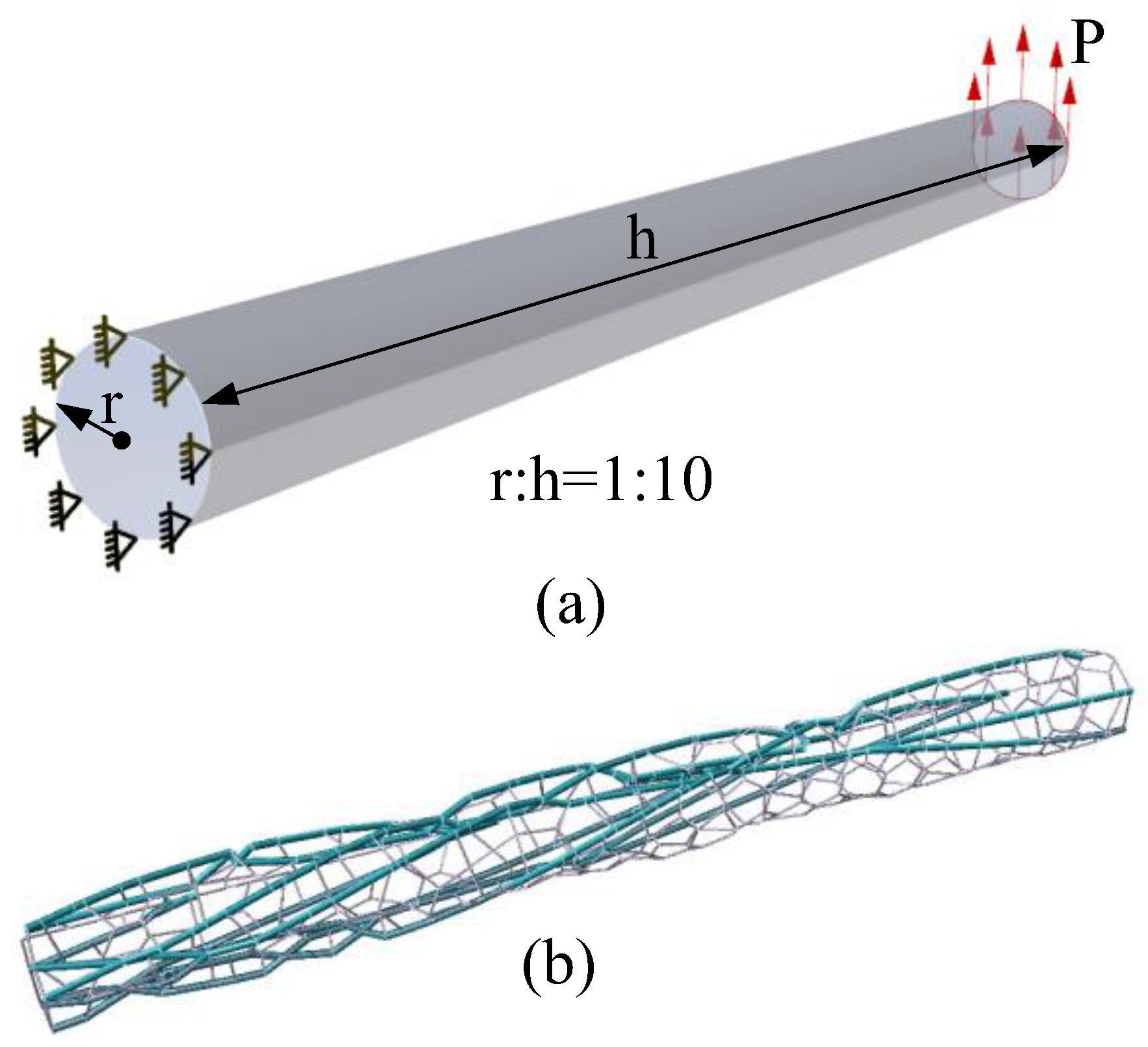
The load and support conditions in the design domain of the thin-walled shell are shown in
Figure 24(a) the ratio of section radius to length r:h=1:10, and the load P=1.
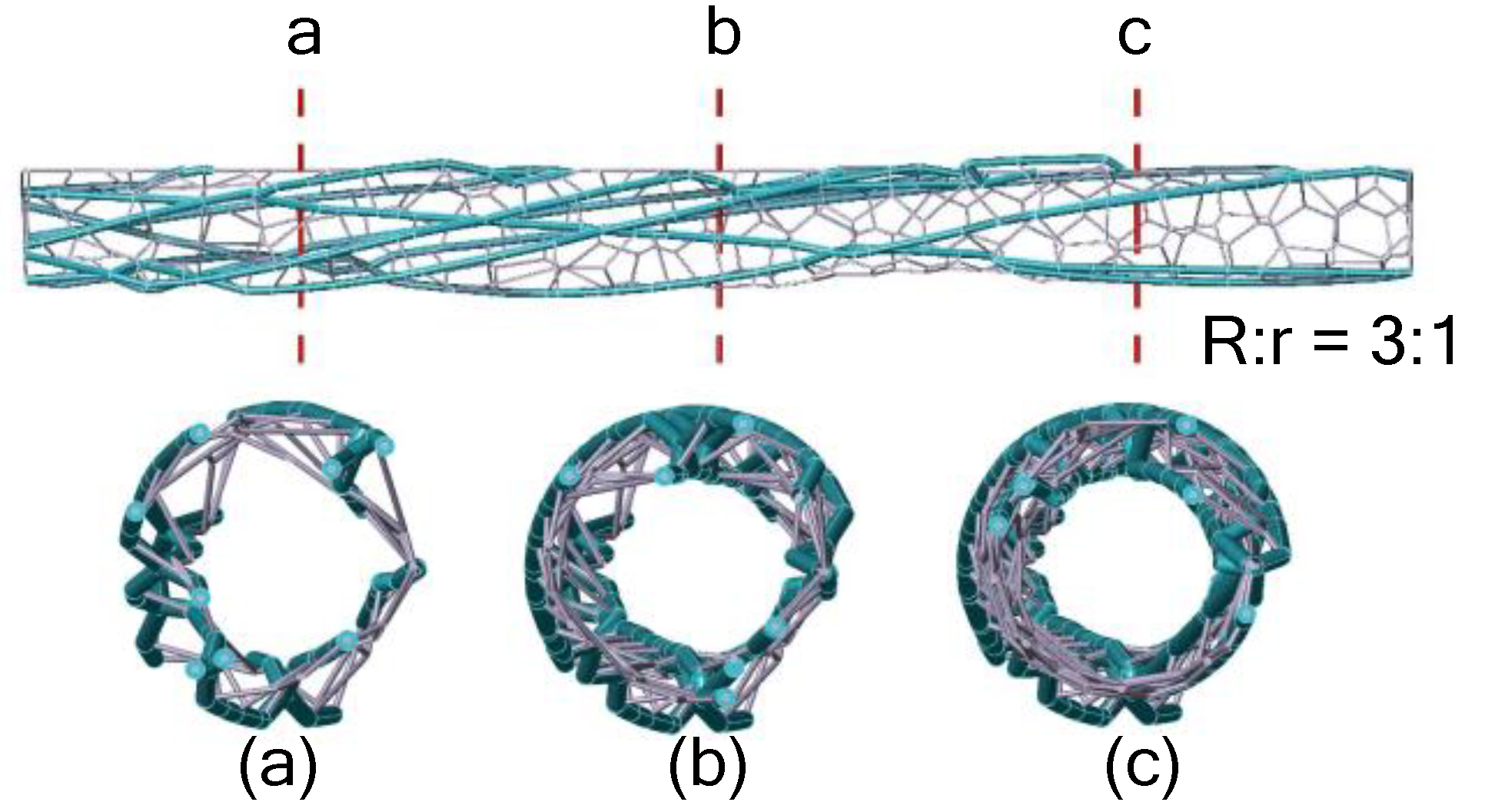
Figure 24(b) shows the optimized grid structure in the design domain of the airfoil surface, and the folding in the structure are shown in
Figure 25, the ratio of section radius R of the branch structure to that of the filled grid is 3:1. As can be seen from
Figure 25, the entire structure is wrapped around the thin-walled shell. As shown in
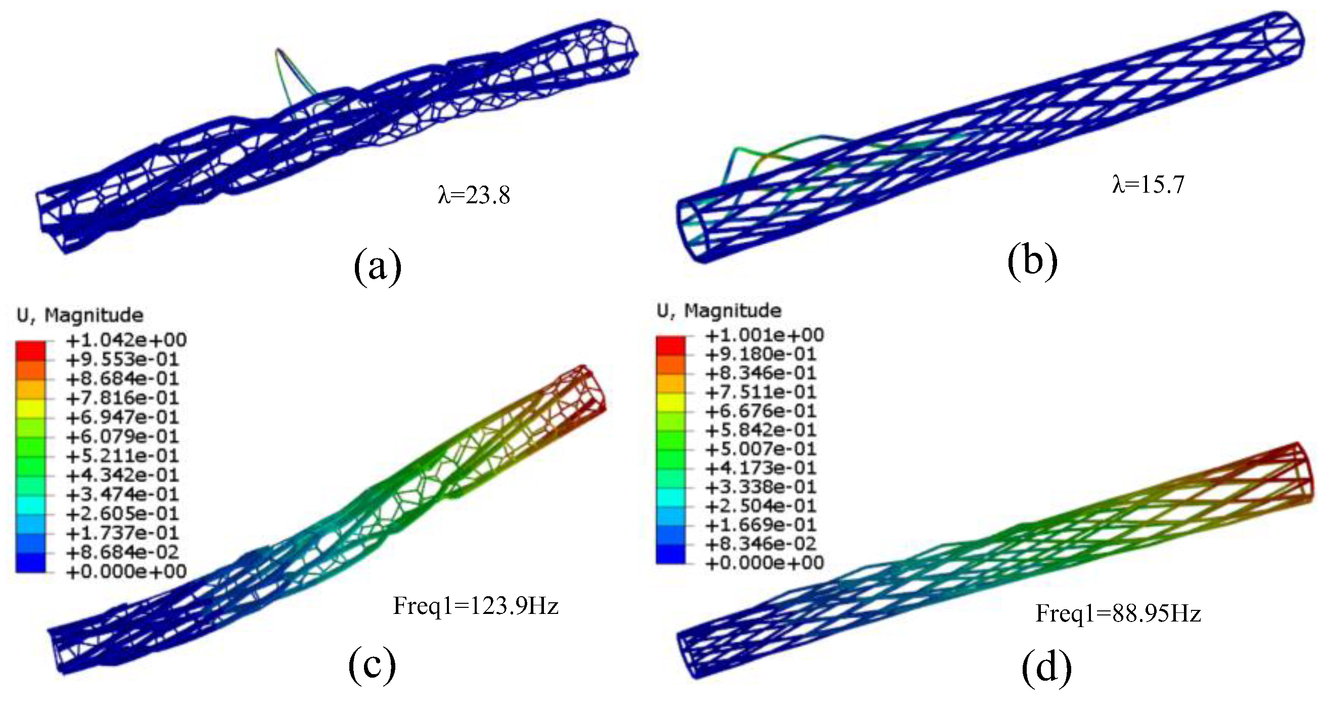
Figure 26, under the same load and support conditions, compared with the quadrilateral grid structure, the buckling load of the folded grid structure biomimetic dragonfly's wing vein increases by 1.5 times, and the first-order modal frequency of the structure increases by 1.4 times.
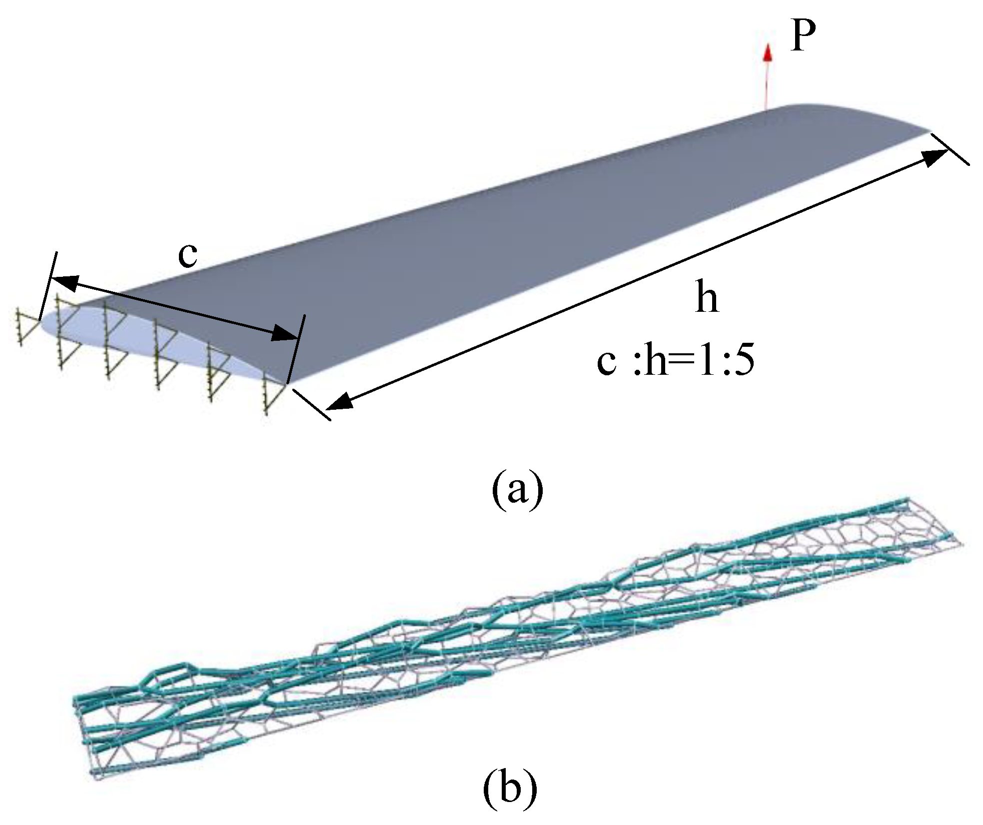
The load and support conditions in the design domain of the airfoil surface are shown in
Figure 27(a), the chord to length ratio c:h=1:5, and the load P=1.
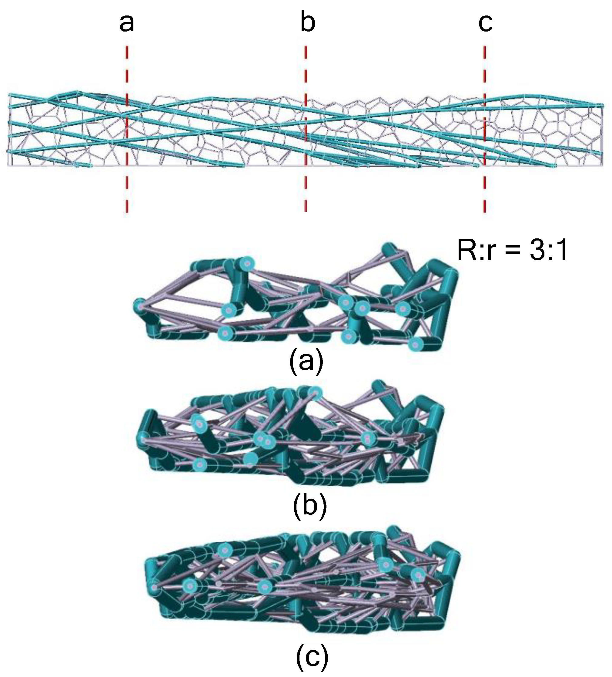
Figure 27(b) is the optimized grid structure in the design domain of the airfoil surface, and the folding in the structure are shown in
Figure 28, the ratio of the section radius R of the branch structure to that of the filled grid r is 3:1. The whole structure is wrapped around the surface of the wing like a rattan man. As shown in
Figure 29, under the same load and support conditions, compared with quadrilateral grid structure, the buckling load of the folded bionic dragonfly vein structure is nearly 4 times higher, and the buckling load is mainly borne by the branch structure. The filling grid structure increases the first-order modal frequency of the whole structure by 1.8 times. This grid structure design structure by simulating dragonfly's wing veins can provide a new idea for the design of airfoil structure.
Figure 1.
dragonfly wing.
Figure 1.
dragonfly wing.
Figure 2.
Symmetrical waves occur at regular intervals along the chord length. A cross-sectional photograph of both the fore and hind wings of a dragonfly is depicted via the positions indicated in the diagram at the top. (Okamoto et al. [
15]).
Figure 2.
Symmetrical waves occur at regular intervals along the chord length. A cross-sectional photograph of both the fore and hind wings of a dragonfly is depicted via the positions indicated in the diagram at the top. (Okamoto et al. [
15]).
Figure 3.
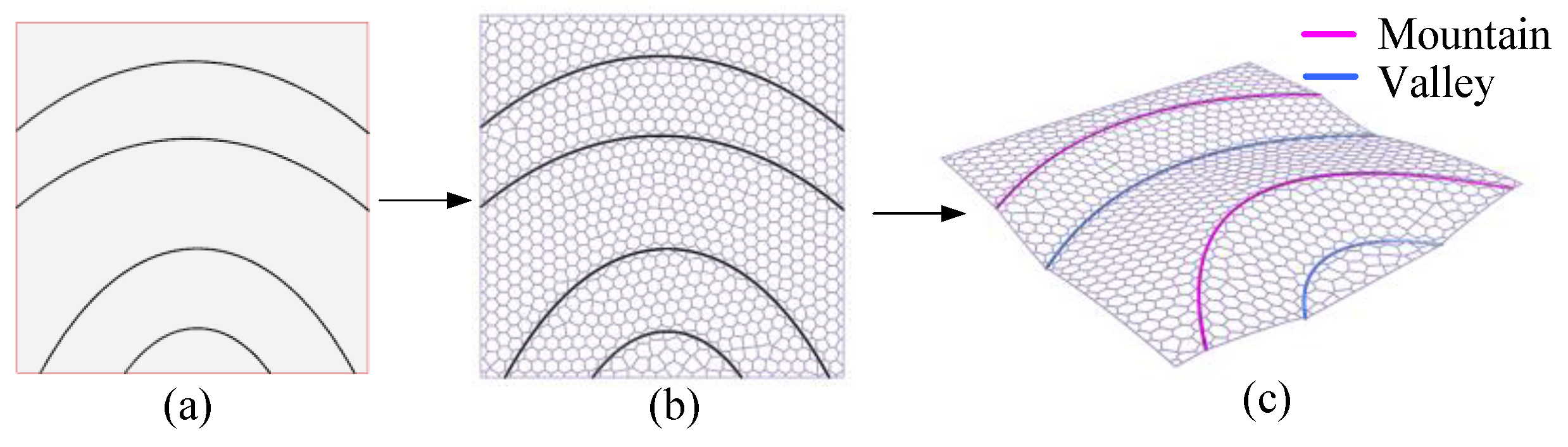
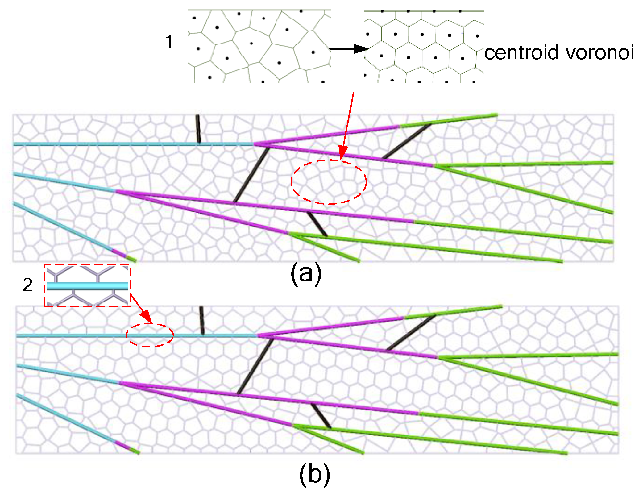
Simulation of the dragonfly wing grid structure generation process: (a) divide the domain into different areas; (b) fill the grid structure in the divided area; (c) Fold the grid structure with the dividing line as the folding line.
Figure 3.
Simulation of the dragonfly wing grid structure generation process: (a) divide the domain into different areas; (b) fill the grid structure in the divided area; (c) Fold the grid structure with the dividing line as the folding line.
Figure 4.
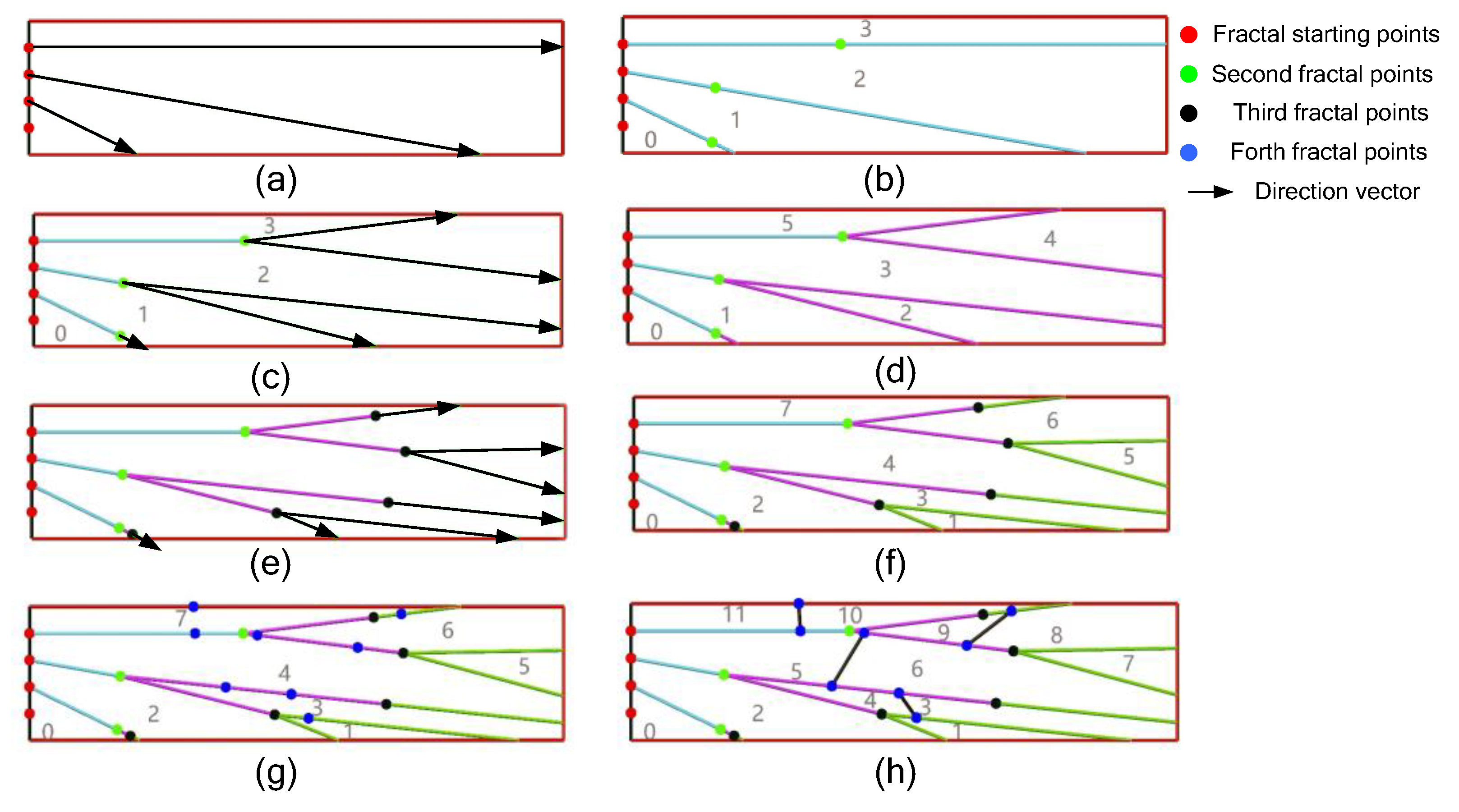
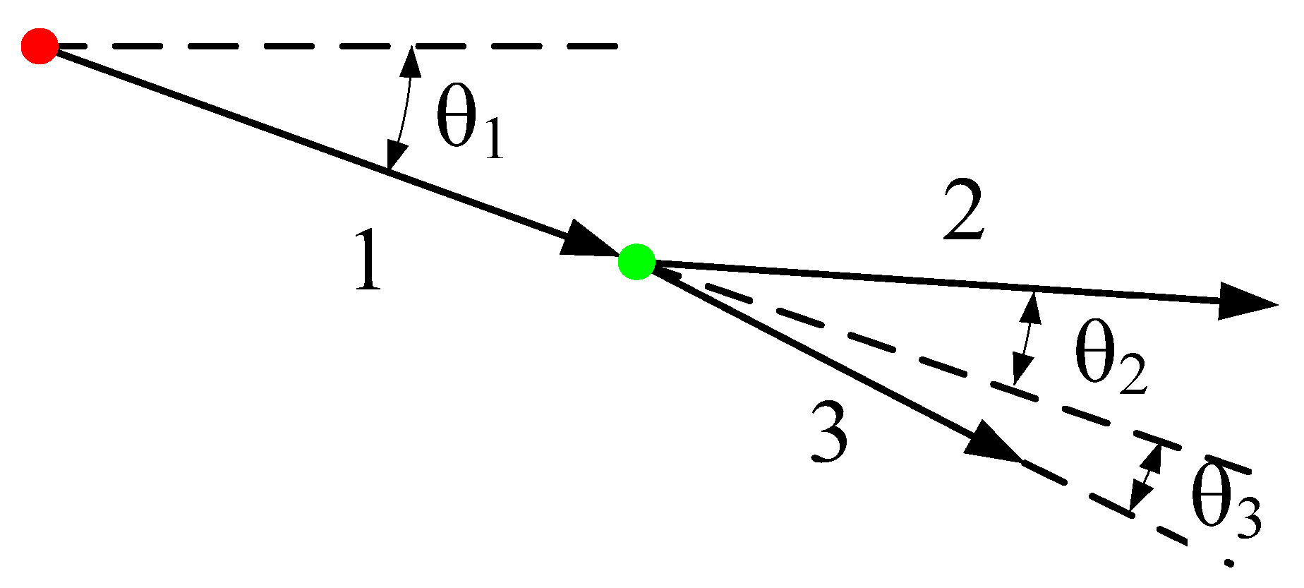
Generation process of main vein branch structure: (a) selects the starting point of the first branch and determines the direction vector; (b) generates the starting point of the second branch; (c) determines the direction vector of the second branch; (d) generates the second branch; (e) generates the starting point of the third branch and determines the direction vector of the third branch; (f) generates the third branch; (g) and (h) add the enhanced branch.
Figure 4.
Generation process of main vein branch structure: (a) selects the starting point of the first branch and determines the direction vector; (b) generates the starting point of the second branch; (c) determines the direction vector of the second branch; (d) generates the second branch; (e) generates the starting point of the third branch and determines the direction vector of the third branch; (f) generates the third branch; (g) and (h) add the enhanced branch.
Figure 5.
The direction vector of the branch is determined. The red dot is the starting point of the first branch and the direction vector control parameters of the first branch is θ1; the green dot is the starting point of the second branch; θ2 and θ3 are the direction vector control parameters of the second branch.
Figure 6.
The Voronoi grid is filled in different regions of the segmentation: (a) initial Voronoi filling grid; (b) filling grid becomes centroid Voronoi grid.
Figure 6.
The Voronoi grid is filled in different regions of the segmentation: (a) initial Voronoi filling grid; (b) filling grid becomes centroid Voronoi grid.
Figure 7.
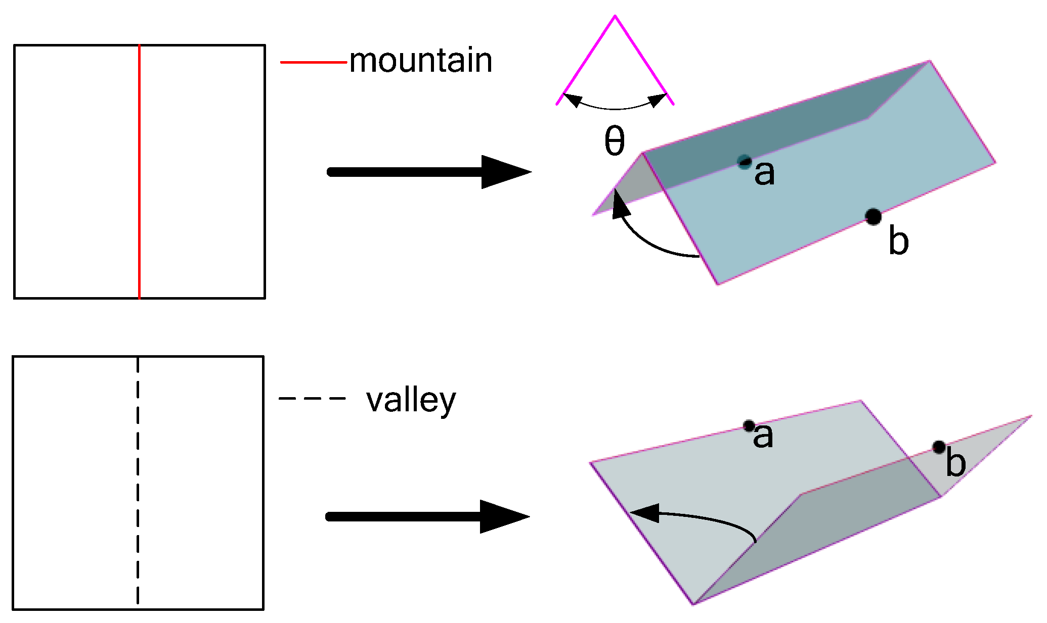
M-V Definition: Fold clockwise along the M fold line with a positive folding angle θ, and fold counterclockwise along the V fold line with a negative folding angle -θ, When the folding angle is 180°, point a and point b are folding coincidence points.
Figure 7.
M-V Definition: Fold clockwise along the M fold line with a positive folding angle θ, and fold counterclockwise along the V fold line with a negative folding angle -θ, When the folding angle is 180°, point a and point b are folding coincidence points.
Figure 8.
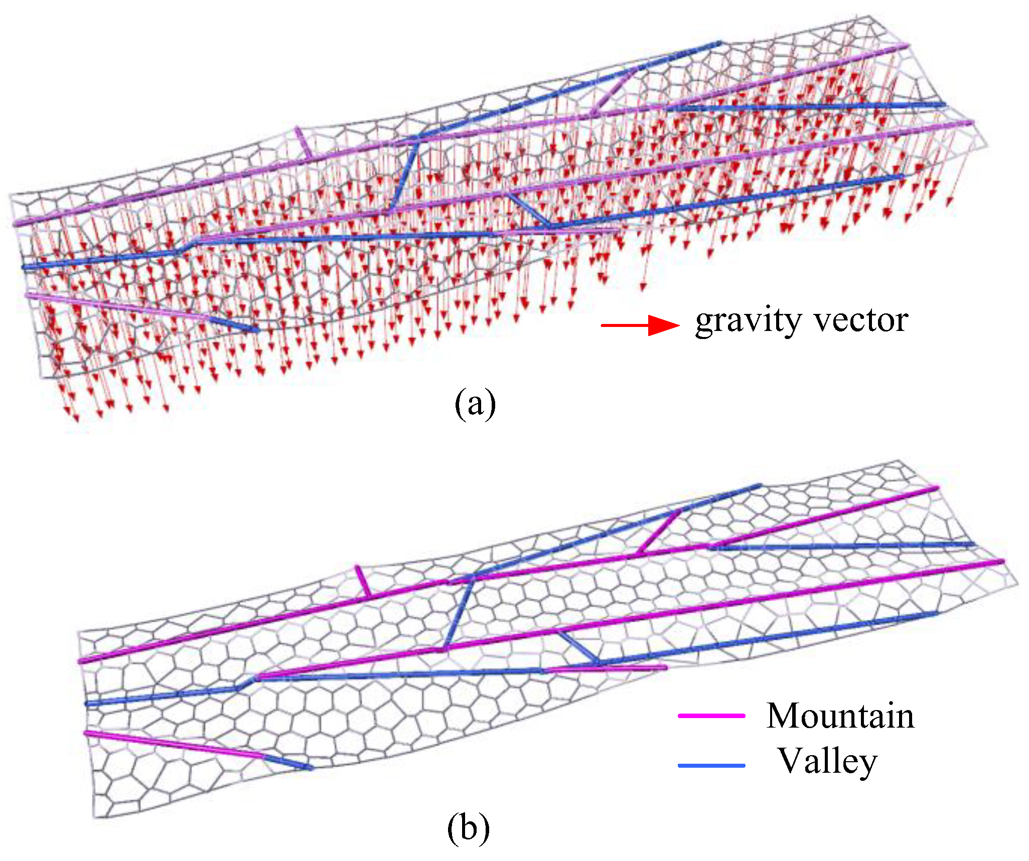
In the process of a plane grid structure changing into a fold grid structure: (a)In order to quickly make the grid structure reach a balanced and stable state in the folding process the gravity direction load is increased at the nodes; (b) folded grid structure.
Figure 8.
In the process of a plane grid structure changing into a fold grid structure: (a)In order to quickly make the grid structure reach a balanced and stable state in the folding process the gravity direction load is increased at the nodes; (b) folded grid structure.
Figure 9.
cross-section of the fold grid structure.
Figure 9.
cross-section of the fold grid structure.
Figure 10.
Adding an offset to the start of the second-generation branch of the same branch generates leaf veins liked structure.
Figure 10.
Adding an offset to the start of the second-generation branch of the same branch generates leaf veins liked structure.
Figure 11.
To generate the dragonfly vein, (a) divides the wing into different regions with the vein line generated by the above method; (b) adds the normal phase vector offset to the straight vein line and turns it into a curve form; and (c) adjusts the position and direction of the normal phase vector to make the vein line close to the real vein form.
Figure 12.
Centroid Voronoi grid is filled in: (a) The discrete structure points in the branch region are used to generate polygonal grid; (b) the initially generated polygonal grid (green); and (c) the grid is homogenized to generate the final centroid Voronoi grid, (d) The generated 2D vein grid structure.
Figure 13.
The load distribution increased at the grid structure node: (a) near the wing root region; (b) near the edge region.
Figure 13.
The load distribution increased at the grid structure node: (a) near the wing root region; (b) near the edge region.
Figure 14.
The process of forewing model folding structure: (a)The wing veins are defined as folding lines: M=6, V=7; (b) Fold generating after the folding lines definition is completed; (c) fold becomes obvious; (d) With the increase of folding angle, part of the grid does not reach the stable state; (e) the final stable state of the three-dimensional forewing model.
Figure 15.
final forewing three-dimensional model: (a) forewing model fold structure; (b) in the quadrilateral area, the boundary of quadrilateral element will directly become the folding line; (c) In the pentagonal and hexagonal area, the offset of folding is small.
Figure 15.
final forewing three-dimensional model: (a) forewing model fold structure; (b) in the quadrilateral area, the boundary of quadrilateral element will directly become the folding line; (c) In the pentagonal and hexagonal area, the offset of folding is small.
Figure 16.
The cross-section corrugated structure of the forewing model. The variation of corrugations along the chord length is shown in the four sections. The depth of the fold decreases gradually from the leading edge to the trailing edge, and the depth of the fold is 0.26-0.56mm.
Figure 16.
The cross-section corrugated structure of the forewing model. The variation of corrugations along the chord length is shown in the four sections. The depth of the fold decreases gradually from the leading edge to the trailing edge, and the depth of the fold is 0.26-0.56mm.
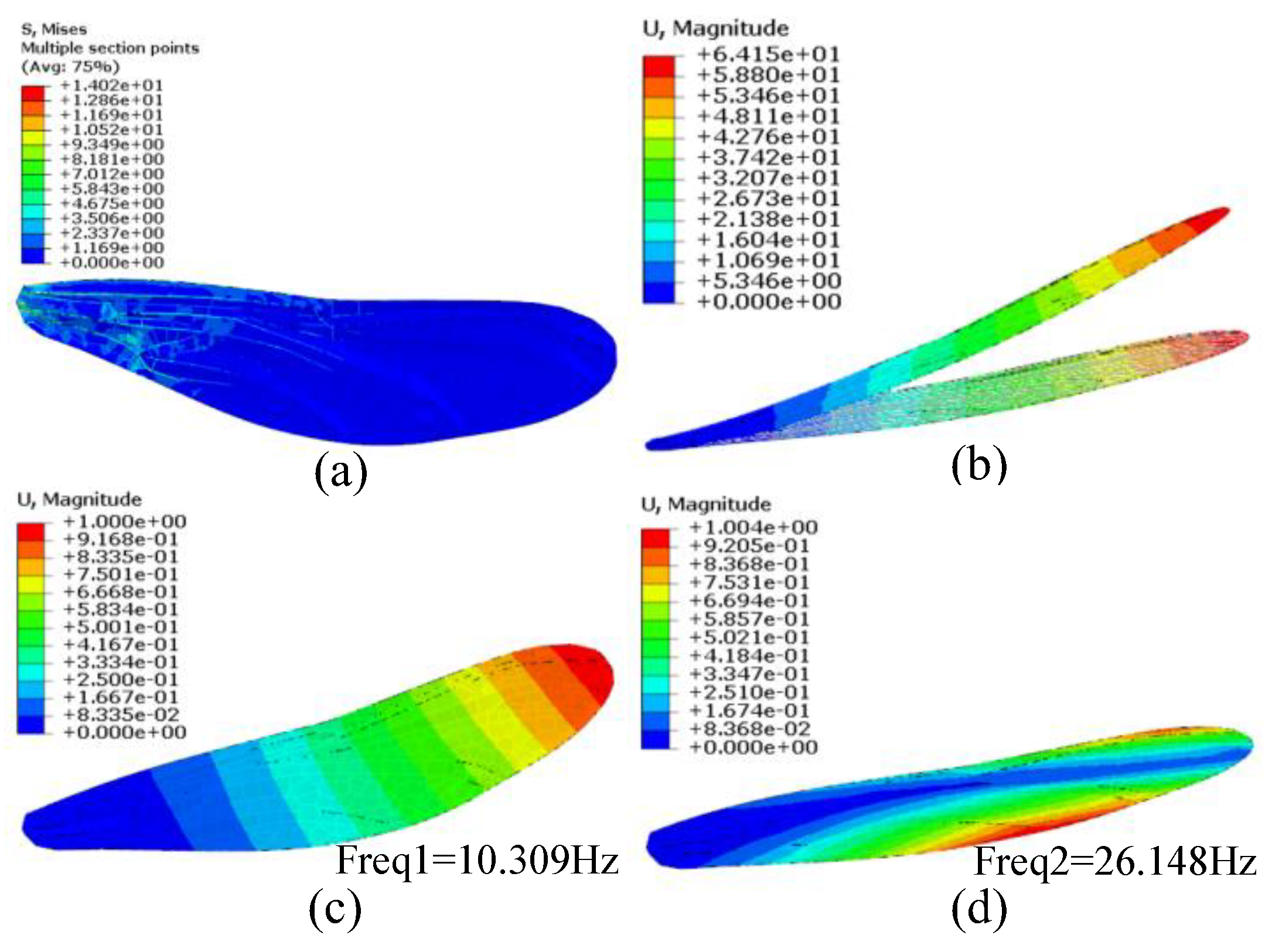
Figure 17.
Finite element analysis of the forewing model: (a) stress of the dragonfly wing; (b) displacement of the dragonfly wing; (c) first mode frequency; (d) second mode frequency. The weight of dragonfly m=865.3mg, the wing area Af=713.32mm2, and the average load on the wing surface is qave, .
Figure 17.
Finite element analysis of the forewing model: (a) stress of the dragonfly wing; (b) displacement of the dragonfly wing; (c) first mode frequency; (d) second mode frequency. The weight of dragonfly m=865.3mg, the wing area Af=713.32mm2, and the average load on the wing surface is qave, .
Figure 18.
Biomimetic grid structure design application process.
Figure 18.
Biomimetic grid structure design application process.
Figure 19.
Two-dimensional plane design: (a) Two-dimensional design domain; (b) Structure obtained by simulating dragonfly wing veins.
Figure 19.
Two-dimensional plane design: (a) Two-dimensional design domain; (b) Structure obtained by simulating dragonfly wing veins.
Figure 20.
The structure cross-section obtained by simulating dragonfly wing vein, r is the radius of branch structure, r is the radius of filling grid.
Figure 20.
The structure cross-section obtained by simulating dragonfly wing vein, r is the radius of branch structure, r is the radius of filling grid.
Figure 21.
The bionic vein grid structure is compared with the quadrilateral grid structure. The results show that the weight difference between the two structures is less than 3%, under the same load and support conditions, compared with the quadrilateral grid structure, the buckling load of the grid structure biomimetic dragonfly's wing vein increases 11%, and the first-order modal frequency of the structure increases by 2.6 times: (a) Buckling of biomimetic vein grid structure; (b) buckling of quadrilateral grid structure; (c) the first mode of biomimetic vein grid structure; (d) the first mode of quadrilateral grid structure.
Figure 22.
Elliptic design domain: (a)ellipsoidal domain under a distributed loading; (b) structure solution obtained for ellipsoidal domain,and the section radius R of the branch structure to the filled grid r is 3:1.
Figure 22.
Elliptic design domain: (a)ellipsoidal domain under a distributed loading; (b) structure solution obtained for ellipsoidal domain,and the section radius R of the branch structure to the filled grid r is 3:1.
Figure 23.
Comparing the bionic vein grid structure with the quadrilateral grid structure, the weight difference between the two structures is less than 4%, under the same load and support conditions, compared with the quadrilateral grid structure, the buckling load of the grid structure biomimetic dragonfly's wing vein increases 74.2%, and the first-order modal frequency of the structure increases by 32%: (a) bionic vein grid structure; (b) quadrilateral grid structure buckles; (c) bionic vein grid structure first-order mode; (d) quadrilateral grid structure first-order mode.
Figure 24.
Design domain of the thin-walled shell (a) Thin-walled cylinder design domain; (b) Thin-walled cylinder grid structure of biomimetic dragonfly wing veins.
Figure 24.
Design domain of the thin-walled shell (a) Thin-walled cylinder design domain; (b) Thin-walled cylinder grid structure of biomimetic dragonfly wing veins.
Figure 25.
Cross-section diagram of thin-walled cylinder grid structure of biomimetic dragonfly's wing vein in which R is the radius of main structure and r is the radius of filling grid.
Figure 25.
Cross-section diagram of thin-walled cylinder grid structure of biomimetic dragonfly's wing vein in which R is the radius of main structure and r is the radius of filling grid.
Figure 26.
Comparing the bionic vein grid structure with the quadrilateral grid structure, the weight difference between the two structures is less than 5%, under the same load and support conditions, compared with the quadrilateral grid structure, the buckling load of the folded grid structure biomimetic dragonfly's wing vein increases 52%, and the first-order modal frequency of the structure increases 39.3%: (a) bionic vein grid structure buckles; (b) quadrilateral grid structure buckles; (c) bionic vein grid structure first-order mode; (d) quadrilateral grid structure first-order mode.
Figure 27.
Design domain of the airfoil surface: (a) Airfoil design domain; (b) The wing surface grid structure of biomimetic dragonfly wing veins.
Figure 27.
Design domain of the airfoil surface: (a) Airfoil design domain; (b) The wing surface grid structure of biomimetic dragonfly wing veins.
Figure 28.
Section diagram of curved grid structure of biomimetic dragonfly wing vein, where R is the radius of main structure, r is the radius of filling grid.
Figure 28.
Section diagram of curved grid structure of biomimetic dragonfly wing vein, where R is the radius of main structure, r is the radius of filling grid.
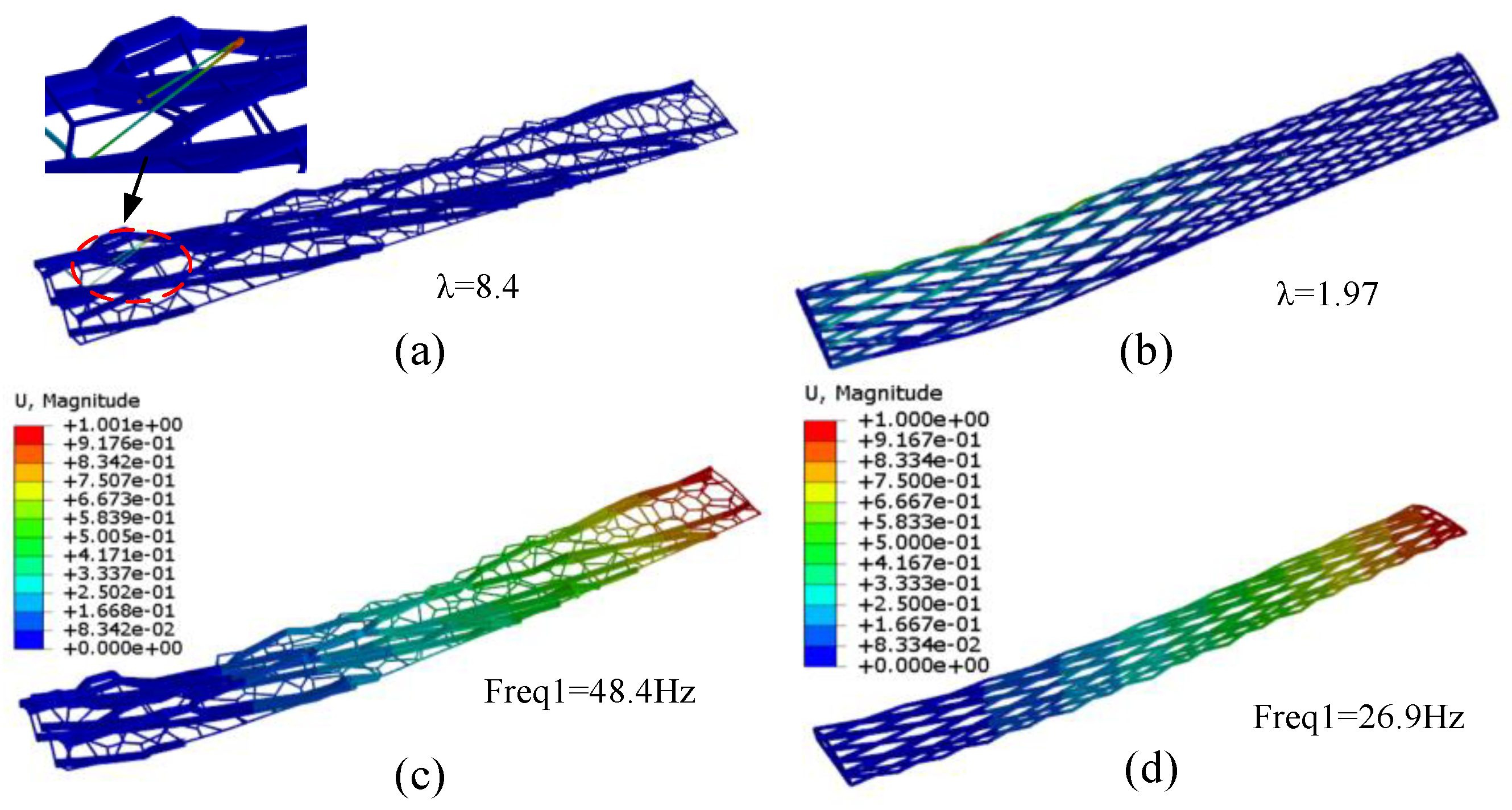
Figure 29.
The comparison between bionic vein grid structure and quadrilateral grid structure shows that the weight difference between the two structures is less than 5%, the buckling load of the folded bionic dragonfly vein structure is nearly 4 times higher, and the buckling load is mainly borne by the branch structure. The filling grid structure increases the first-order modal frequency of the whole structure by 1.8 times: (a) The buckling of biomimetic vein grid structure mainly occurs in the filled grid; (b) Quadrilateral grid structure buckling; (c) simulates the first-order mode of vein grid structure; (d) quadrilateral grid structure.
Table 1.
Material parameters.
Table 1.
Material parameters.
| Material parameters |
|
| E1 [N/mm2] |
134,000 |
| E2 = E3 [N/mm2 ] |
7,900 |
| ν12 =ν13 |
0.33 |
| G12 = G13 [N/mm2 ] |
4,620 |
| G23 [N/mm2 ] |
3,200 |