1. Introduction
In mechanical systems, the gear mechanisms play a vital role in the optimal performance of reliability and efficiency. Transmitting rotational motion and torque between the shafts are the main targets of gear mechanism systems. Nowadays, people are interested in reduced-weight gear systems that have high load capacity and increased strength in gear design and transmission based on factors such as tooth analysis, tooth modification, helix angle, etc. Among all the several types of gear used in industries, Double helical gear is mostly recognized for its unique advantages. It is quite like the herringbone gear except grooving in the center, which is a combination of right-handed and left-handed helical gears with the same helix angle and is used to transmit power in the parallel shafts. While having all the common advantages between helical gear and double helical gear, it also can cancel the axial thrust forces effectively and even has great load capacity, enhanced stability, high efficiency, reduced vibration, and noise. It is widely used in high-precision and critical machinery, automotive, aerospace applications, powerplants, marine propulsion systems, heavy-duty gearboxes, and so on. Double helical gears are the most used components for high load and high-speed applications due to the fact of balancing the maximum forces. For these types of gears, the helix angle affects mostly their overall performance and efficiency which is now a fresh topic for researchers. It is known that wrong values of helix angle can lead to decreased efficiency, failure, and increased stress. Consequently, we need to acknowledge the disadvantages and effects on the operations of double helical gears based on the variation of helix angles. Most of the works till now have tried to enhance the efficiency and performance by the optimization of the design process, FEA method, material characteristics, advanced manufacturing, and simulation techniques.
2. Literature Review
Earlier the geometry of helical gears was explained by changing the helix angle and face width with the help of quite simple mathematical equations. However, Muthu Veerappan et al and Rao et al (1992) discussed the effects of helix angle on the root stress of the gears based on the derived equations. Presently, researchers have already worked on spur and helical gears using the finite element method with the required equations to analyse the bending stress and deformation but not in the case of double helical gears. Mohanraj et al. (2019) conducted a comparative study on single and herringbone helical gears using Finite Element Analysis (FEA) and theoretical methods based on AGMA standards, emphasizing the importance of tooth bending stress in-gear performance. Studies by Wei Li et al. (2018) and Seok-chul Hwang et al. (2013) have shown that errors during machining and gear meshing significantly affect temperature distribution and contact stress, which in turn influence gear performance and durability. Lisle et al. (2017) and Peng et al. (2018) employed FEA and strain gauge techniques to investigate bending stress and load distribution respectively, proving that maximum bending stress occurs at the tooth root and is influenced by tooth geometry and modifications. Further research by Patil et al. (2017) and Jabbour and Asmar et al. (2015) explored the critical load scenarios and stress distribution along the gear tooth, highlighting the necessity of precise design to minimize stress concentrations. The effects of helix angle, friction coefficients, and gear misalignment on contact stress were studied by Santosh S. Patil et al. (2014) and Osman Asi et al. (2006), who noted that misalignment can lead to fatigue crack initiation. Jing Wei et al. (2018) and He Zeyin et al. (2017) supplied insights into dynamic transmission errors and mathematical modelling of helical gears, emphasizing the need for robust design to ensure stability and reduce transmission errors. This body of research underscores the complexity of helical gear design and the critical role of stress analysis in enhancing gear performance and reliability. Zhang et al. (1999) approached to evaluate the details of the stress distribution for spur and helical gears and said the significance of the geometrical parameters like helix angle and face width in figuring out the state of stresses during the design of gears.
While evaluating the design of a double helical gear, some basic parameters like module, helix angle, pressure angle, tool profile, face width, centre distance, number of teeth, addendum, dedendum, backlash, etc need to be carefully considered. Also, the material, lubrication, manufacturing tolerances, thermal considerations, and load distributions must be analysed and upgraded properly during the design process to improve effectiveness. However, it is an overly complicated task to achieve all the necessary properties with the desired performance.
In this paper, the primary aim is to develop the design for double helical gears and to study a comprehensive structural analysis based on simulation using SolidWorks and Ansys software respectively. Our research focuses on the key performance parameters like bending stress, strain, and deformation by varying helix angle conditions systematically and identifying the optimized helix angle for enhanced performance. It also aspires to identify the parameters that will increase the efficiency and durability of double helical gears reducing maintenance costs. This study can lead to better energy utilization, extend operational life, reduce material wastage, reliability, low manufacturing costs, and contribute to advanced mechanical engineering knowledge. It may also serve as a reference for further research and development of gearbox designs.
3. Methodology
For this paper, firstly the design of double helical gear using Solid Works software is completed. In design some parameters are constant, and some parameters are variable. Variable parameters are pressure angle and helix angle. Typically, two types of pressure angles in double helical gears like 14.5 and 20. Design variable parameter helix angle change five times under the pressure angle 20. Again, change the helix angle five times under the pressure angle of 14.5. After designing the gear structure analysis using the finite element method, the tangential force is applied directly to the gear teeth, and the assumed fixed support is the shaft diameter. The considered parameters values are given in
Table 3.1. Then, ANSYS measured the bending stress, strain, and deformation value. This numerical value is justified by the experimental value using AGMA standards equations.
Table 3.1.
Parameters considered for this study.
Table 3.1.
Parameters considered for this study.
| PARAMETERS |
SPECIFICATIONS |
| Module(m) |
16 mm |
| Face width (b) |
100 mm |
| Pitch diameter (d) |
800 mm |
| Number of teeth |
50 |
| Hub diameter |
200mm |
| Gear speed (N) |
1500 rpm |
| Power (p) |
100 KW |
| Power source |
Uniform |
| Types of loads |
Continuous |
| Safety factor |
1.1 |
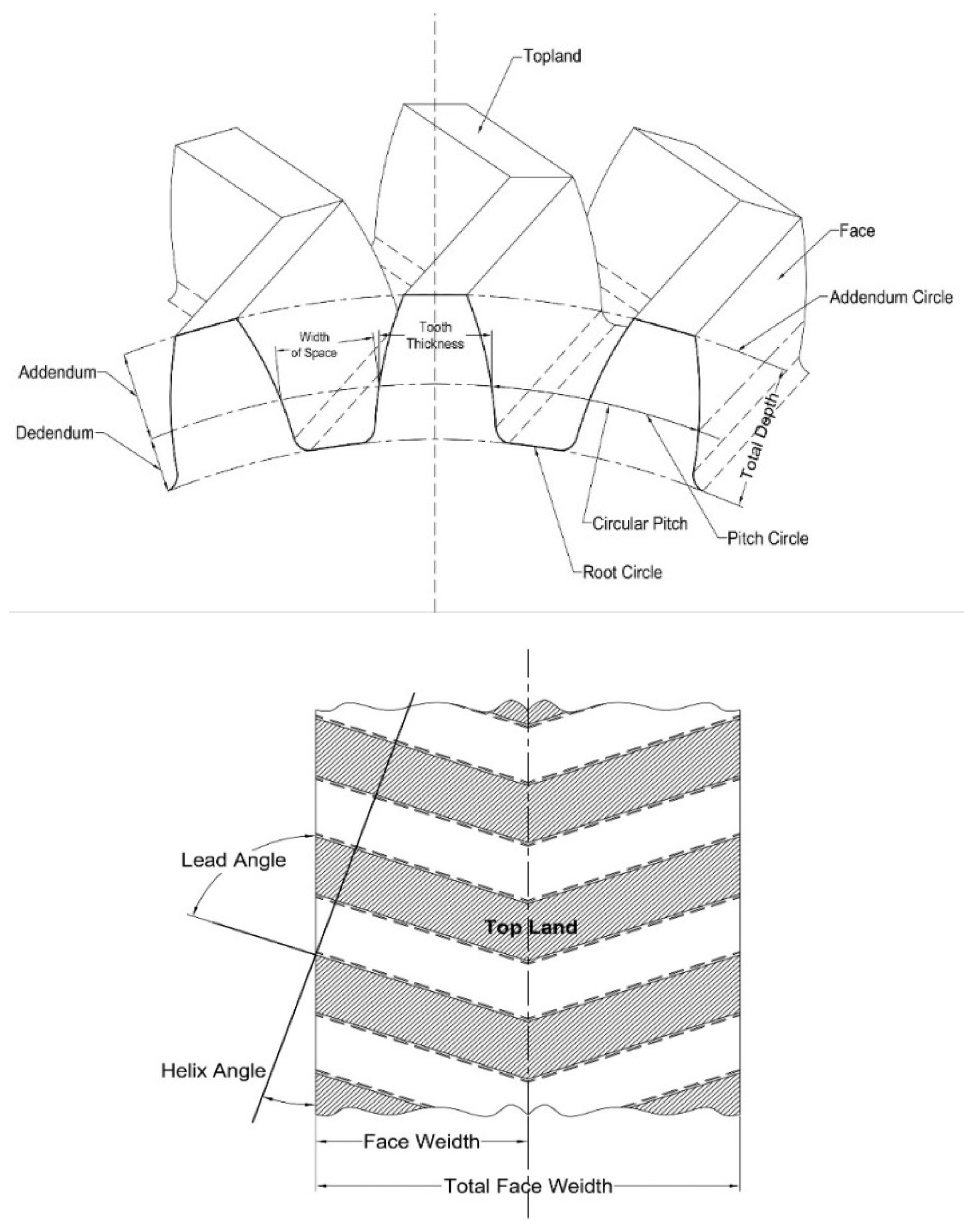
3.1. Geometry
Figure 3.1.1.
Design Parameters.
Figure 3.1.1.
Design Parameters.
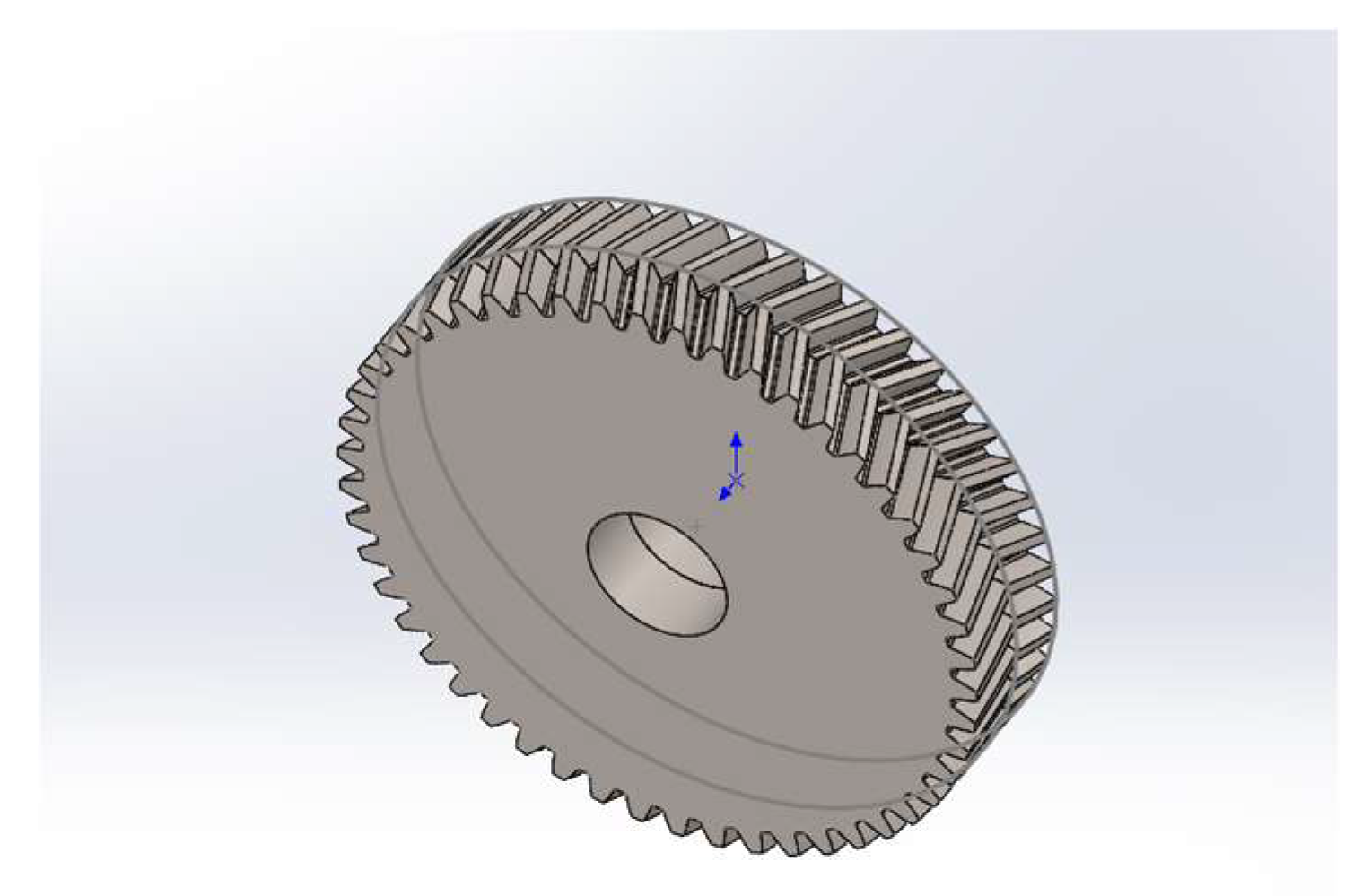
Figure 3. 1.2.
Double helical gear using Solid Works software.
Figure 3. 1.2.
Double helical gear using Solid Works software.
3.2. Boundary Conditions
There are several boundary conditions in double helical gear for measuring stress, strain, and deformation using different geometry.
Materials properties:
In the design and simulation of double helical gear using materials structural steel, the material's properties are:
Young modulus: Pa
Poisson’s ratio:0.3
Bulk modulus: Pa
Shear modulus: Pa
Condition of load:
In double helical gear, applied torque distribution along the gear teeth.
The applied force distribution directs the gear teeth due to the torque.
The shaft diameter of the double helical gear is fixed.
Assumptions:
The double helical gear teeth are perfectly shaped without manufacturing error.
The double helical gear materials are homogeneous and isentropic.
The helical gear’s helix angle changes along the tooth profile.
Uniform distribution of load along the line of action (contact line).
The gear materials properties are constant such as Young’s modulus, Poisson’s ratio, bulk modulus, etc.
3.3. Governing Equations
Double helical gear stress measuring for different helix angles using some governing equations. For a solid in equilibrium, the forces in each of the three coordinate directions (x, y, z) and the moments of each axis must satisfy the following equations:
Where:
are the normal stress components.
are the shear stress components.
are the body forces per unit volume in the x, y, and z directions, respectively.
Torque T =
Tangential force (Ft)=
Or Tangential force (Ft)=
Separate force S=
Here, α=pressure angle, β=helix angle
Stress σ=
Here, j= Double helical gear geometry factor
Kv = velocity factor.
Ko = overload factor.
Km = load distribution factor.
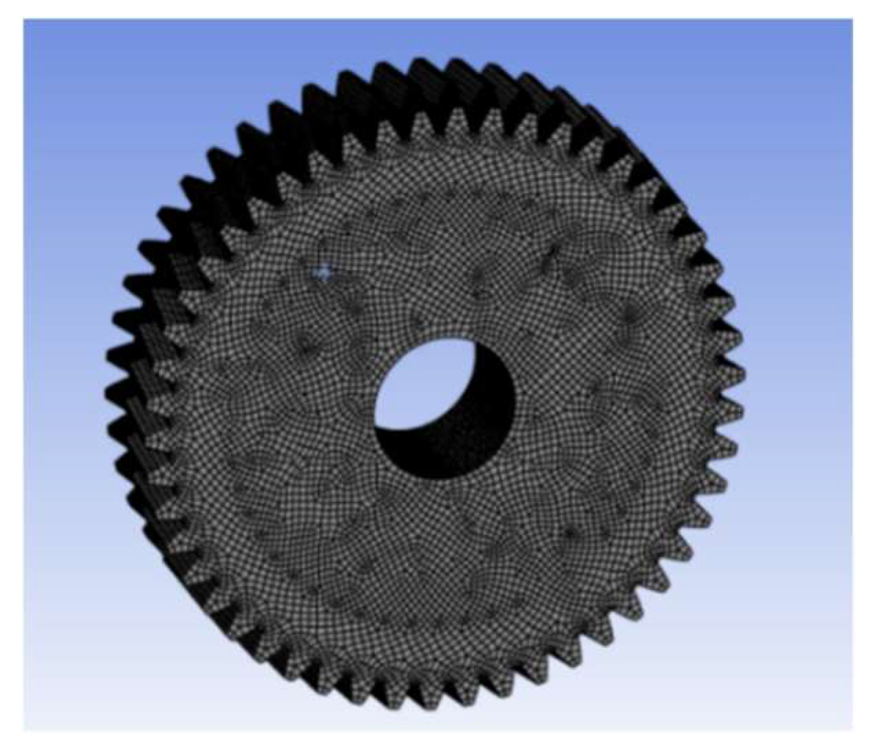
3.4. Mesh Refinement Test
Mesh generation: Initially create a general mesh in double helical gear using the Finite Element Method.
For the meshing refinement process, divide the whole design into small elements.
The element size is =0.01mm.
For different helix angles and constant face width =100mm,
The average number of elements = 412405, which is highly refined mesh.
And the average number of nodes = 865929
Figure 3.4.1.
general mesh refinement.
Figure 3.4.1.
general mesh refinement.
3.5. Code Validation
Find out the mechanical properties (stress, strain, deformation) of double helical gear for different helix angles using the Finite Element Method. On the other hand,
Calculate the experimental value by AGMA (American Gear Manufacturing Association) standard equations and validate the numerical value.
The calculation of the bending stress of the double helical gear, equation given by (Auwalu et al.2019)
Stress σ =, Here, 0.93 is the mounting constant of helical gear.
Tangential force Ft=
=
=1591.67 N ~1591 N
Now,
Face width, b=100 mm
Module, m=16 mm
Load distribution factor, Km=0.3
Velocity factor, Kv=1
Overload factor, Ko=1.25
Geometry factor for double helical gear, j=0.22, helix angle =10
0.15(small helix angle) -0.30(large helix angle)
Stress (AGMA) = =1.576 MPa
Numerical stress = 1.5436 MPa
Stress error = = = 2.22%
If varying face width, now stress calculation:
Let, face width = 150mm, and helix angle =10,
Numerical stress in 150-face width = 0.91MPa
Stress (AGMA) = =1.05MPa
Stress error = = =13.41%
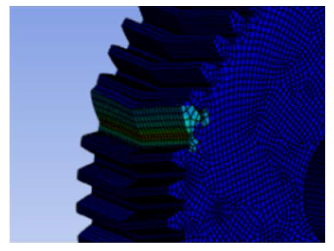
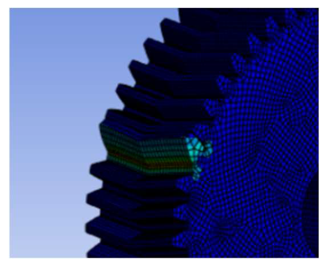
Figure 3.5.1.
Stress analysis of double helical gear teeth 50 and helix angle 10 degrees under the pressure angle 20 degrees.
Figure 3.5.1.
Stress analysis of double helical gear teeth 50 and helix angle 10 degrees under the pressure angle 20 degrees.
Figure 3.5.2.
Strain analysis for a 3D model under pressure angle 20 and helix angle 10.
Figure 3.5.2.
Strain analysis for a 3D model under pressure angle 20 and helix angle 10.
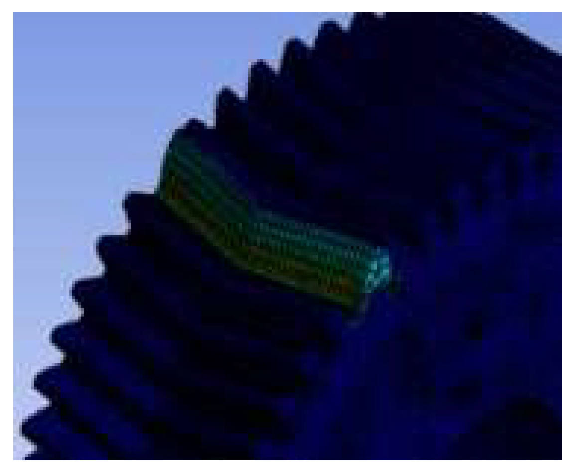
Figure 3.5.3.
Deformation analysis under pressure angle 20 and helix angle 10.
Figure 3.5.3.
Deformation analysis under pressure angle 20 and helix angle 10.
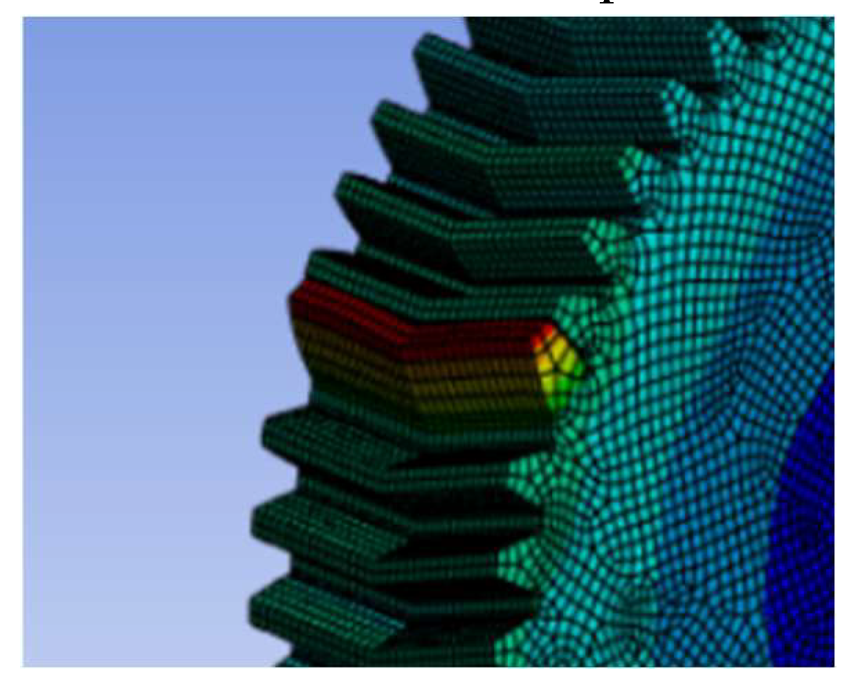
Figure 3.5.4.
Stress analysis under pressure angle 20 with face-width 150 and helix angle 10.
Figure 3.5.4.
Stress analysis under pressure angle 20 with face-width 150 and helix angle 10.
4. Result and Discussion
An analysis of double helical gears with different helix angles and pressure angles was done using ANSYS software to determine their structural performance focusing on load distribution and stress deformation. To determine the stress, strain, and deformation variation with helix angle, different models in double helical gear are made by keeping parameters constant, like face width, number of teeth, module, and pitch diameter.
Table 3.1 shows the parameters of the gear which are kept constant. On the other hand,
Table 4.1 and
Table 4.2 represent the results of bending stress, strain, and deformation of both ANSYS and AGMA with different helix angles under the pressure angle of 20 degrees and 14.5 degrees respectively. Design and simulation of double helical gear for various helix angles (10,15,20,25 and 30 degrees) under the pressure angles (20,14.5 degrees) keeping other parameters, gear speed, and applied load constant are done for analysis.
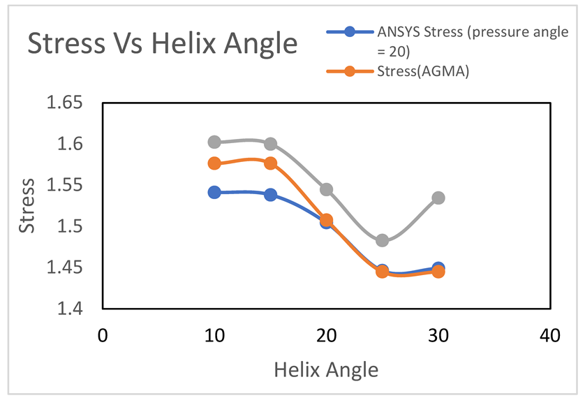
Graph-4.1
As the helix angle gets increased from 10 degrees to 30 degrees, the stresses commonly decrease in these cases. For the blue line, the stress is decreased steadily with an increase in helix angle up to 25 degrees. A similar result is observed in orange line with a higher initial stress level downward. Meanwhile, Green line followed a slightly decreasing arrangement from the highest stress level at first and then it started increasing again.
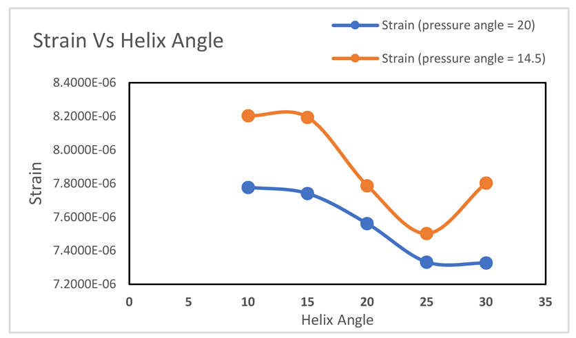
Graph-4.2.
The graph demonstrates the relation between strain and helix angle with different pressure angles which are 20 and 14.5 degrees. In the graph, strain generally decreases when helix angles increase for both pressure angles. It indicates that a higher helix angle results in a lower strain level compared to a lower helix angle. In the case of a 14.5-degree pressure angle, it follows a non-linear trend, decreasing from 10° to 25° and reaching a minimum point, and then starts again to increase after 25°.
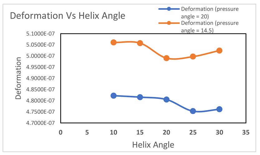
Graph-4.3
The relationship between deformation and helix angle for different pressure angles is plotted in the graph. In the case of a pressure angle of 20 degrees, deformation decreases consistently as the helix angle increases. Meanwhile, at the lower angle of 14.5 degrees, the deformation shows variable behaviours at different angles starting from 10 to 30 degrees.
Table 4.3.
Stress analysis with varying face width.
Table 4.3.
Stress analysis with varying face width.
| Helix Angle |
Face Width(mm) |
Stress (Mpa)(ANSYS) |
Stress (Mpa)(AGMA) |
| 10 |
50 |
2.8812 |
3.1526 |
| 10 |
100 |
1.5413 |
1.5763 |
| 10 |
150 |
0.9111 |
1.0509 |
| 20 |
50 |
3.1077 |
3.0156 |
| 20 |
100 |
1.5046 |
1.5078 |
| 20 |
150 |
0.98031 |
1.0052 |
| 30 |
50 |
2.54 |
2.8899 |
| 30 |
100 |
1.4491 |
1.4450 |
| 30 |
150 |
0.822 |
0.9633 |
Stress change in double helical gear is very negligible when changing the helix angle. The stress difference is greater due to changing the face width than the helix angle. Helix angle and face width are both parameters that affect the stress variation of the double helical gear.
Table 4.3 provides a comparison of the stress values (in MPa) for different helix angles and face widths, as calculated using two methods: ANSYS simulation and AGMA standards.
For every face width, stress decreases as the helix angle increases from 10° to 30° in both ANSYS and AGMA methods. Because, when increasing the helix angle reduces the axial force on the double helical gear. Thereby stress decreases. When the face width of 50 mm, the ANSYS stress value decreases from 2.8812 MPa (10°) to 2.54 MPa (30°), The AGMA stress value also decreases from 3.1526 MPa to 2.8899 MPa.
For every helix angle, increasing the face width leads to a decrease in stress. A large face-width distributes the load over an enormous area, thereby reducing the stress. For a helix angle of 10°, the ANSYS stress drops from 2.8812 MPa at 50 mm to 0.9111 MPa at 150 mm. Similarly, AGMA values decrease from 3.1526 MPa to 1.0509 MPa over the same face width range.
The efficiency improves and reduces wear and tear with a decrease of stress in gear. In both the table, when helix angle is increased, the stress seems to be reduced. However, the stress reduction is seen as very low for a change in helix angle. As the pressure angle is changed, the 20-degree pressure angle is seen to be practicable more than that of 14.5 degrees. In both tables, the stress is seen to be reduced by varying the pressure and helix angles. When the results in ANSYS software are compared to found data in AGMA, at first some differences could be seen though no more significant changes have been found later. When we changed helix angle, the result of stress was found very negligible. Then we kept the angles constant and changed the face widths to check the variations in the stresses. The differences in both ANSYS and AGMA results are greater this time due to changed face widths than fixed face widths. From the data table-2,3 & 4, it can be said that changes in face width and helix angle both affect the stress distribution though variations in face width generally impact more than helix angles.
5. Conclusions
In this analysis, we have seen that the increment of the helix angle and face width results in stress reduction. But, as we increased the face width, stress is seen to be reduced more compared to increased helix angles. For better results, both face width and helix angle need to be increased in such cases. Theoretically, a helix angle of 30 degrees and a face width of 150mm might be the best option to produce the desired gear which is the preferable scenario. However, the manufacturing of a gear that has more helix angle is more complex, thus resulting in more cost. At this point, we can use a software named DOE which helps to provide the optimum angle for the manufacturing process. In conclusion, we can say that we must choose a gear with a helix angle suitable for the design as well as financially feasible for a productive case.
Acknowledgements
The author was only responsible for the conceptualization, methodology, data collection, analysis, and writing of this research paper.
Conflict of Interest
There is no conflict of interest. No external funding was received for this research. The data supporting the findings of this study are available from the author upon reasonable request. This study does not involve human participants, animal subjects or any data that require ethical approval. All procedures performed followed relevant institutional and legal requirements.
References
- L. A. Pillai, N., Sreenivas, N., Krishnaraj, K., Unnikrishnan, V., & Ajith, M. (2018). Thermal performance evaluation of cork phenolic for nozzle external thermal protection system using 250 kW plasma jet facility. Journal of Heat Transfer, 140(7). [CrossRef]
- L. Jian-Kai. (2015). Research on cutting tool wear based on fractional Brownian motion. International Journal of Mechanical Engineering and Applications, 3(1), 1. [CrossRef]
- Zhao, E., Cheng, K., Sun, W., Zhou, Z., & Zhao, J. (2017). Buckling failure analysis of truck-mounted concrete pump’s retractable outrigger. Engineering Failure Analysis, 79, 361–370. [CrossRef]
- Journal of Advanced Research in Dynamical and Control Systems. (2021). Journal of Advanced Research in Dynamical and Control Systems. [CrossRef]
- Raman, R. K. S. (2005). Characterisation of ‘rolled-in,’ ‘fragmented,’ and ‘red’ scale formation during secondary processing of steels. Engineering Failure Analysis, 13(7), 1044–1050. [CrossRef]
- Singh, B. (2017). Hall effect on MHD flow of visco-elastic micro-polar fluid layer heated from below saturating a porous medium. International Journal of Engineering Science and Technology, 9(4), 48–66. [CrossRef]
- Taghipour, J., Dardel, M., & Pashaei, M. H. (2018). Vibration mitigation of a nonlinear rotor system with linear and nonlinear vibration absorbers. Mechanism and Machine Theory, 128, 586–615. [CrossRef]
- Rao, Ch. R. M., & Muthuveerappan, G. (1993). Finite element modelling and stress analysis of helical gear teeth. Computers & Structures, 49(6), 1095–1106. [CrossRef]
- Ibrahim, M. A., Gidado, A. Y., Hussein, A., & Tijjani, N. (2019). Comparison of bending stresses for different face width of helical gear using AGMA and ANSYS. Retrieved from https://www.akademiabaru.com/submit/index.php/aram/article/view/1835.
- Zeng, L., Zang, Y., & Gao, Z. (2017). HOPF bifurcation control for rolling mill multiple-mode-coupling vibration under nonlinear friction. Journal of Vibration and Acoustics, 139(6). [CrossRef]
- Zhang, J. J., Esat, I. I., & Shi, Y. H. (1999). Load analysis with varying mesh stiffness. Computers & Structures, 70(3), 273–280. [CrossRef]
|
Disclaimer/Publisher’s Note: The statements, opinions and data contained in all publications are solely those of the individual author(s) and contributor(s) and not of MDPI and/or the editor(s). MDPI and/or the editor(s) disclaim responsibility for any injury to people or property resulting from any ideas, methods, instructions or products referred to in the content. |
© 2024 by the authors. Licensee MDPI, Basel, Switzerland. This article is an open access article distributed under the terms and conditions of the Creative Commons Attribution (CC BY) license (http://creativecommons.org/licenses/by/4.0/).