
Submitted:
25 November 2024
Posted:
27 November 2024
You are already at the latest version
Abstract
This article explores an innovative methodology for material selection in the automotive industry, integrating the Ashby approach for mechanical performance coefficients as an initial filtering criterion. The Ashby method serves for identifying materials aligned with mechanical properties required by the specific application. Following this initial selection, the study incorporates Multi-Criteria Decision Analysis (MCDA) techniques, specifically the VIKOR method, to comprehensively rank the chosen materials. The evaluation criterion is not limited to mechanical properties, but it encompasses crucial factors for the automotive industry, such as cost considerations and environmental impact measures, this latter evaluated in terms of CO2_eq by means of the Life Cycle Assessment (LCA) methodology. The use of MCDA methods facilitates a holistic decision-making process, acknowledging the multifaceted nature of material choice in the automotive domain. By integrating performance metrics, cost factors, and environmental considerations, such a methodology strives to provide a balanced and sustainable approach to material selection, contributing to advancements in car design. Finally, the conceived method is validated by the application to a practical re-design case study, a motor bracket of a C-segment passenger electric car.
Keywords:
Lightweighting
; Redesign
; VIKOR
; ashby
; automotive
; material selection
; environmental impact
; MCDA methods
1. Introduction
In 2022 global CO2 emissions from energy and transport have increased respectively by 261 Mt and 254 Mt with respect to 2021 levels [1]. Considering the European area, the automotive industry accounts for 20 % of the overall Greenhouse Gas (GHG) emissions [2]. In the light of achieving a 60 % GHG emissions reduction in 2050 compared to 1990 levels (as mandated by European Union policies [3]), lightweighting design has recently been established as one of the most favorable strategies. Lightweight design strongly contributes to pollution reduction by lowering vehicle consumption, as provided by [4], which states that a 10 % mass decrease allows achieving a 5-8 % abatement in energy absorption. By lowering fuel consumption, lightweighting also enables reducing exhaust gas emissions, and consequently the environmental impact caused by passenger cars transportation [5,6,7]. Several case studies from both research and industry field deal with the replacement of conventional materials for specific car components through lighter solutions [8,9,10], providing several advantages in addition to consumption reduction, such as improved vehicle performances (in terms of both acceleration and top speed [11,12]), increased safety by enhancing stability, greater maneuverability, and reduced braking distances [13,14]. Current production and manufacturing technologies make available a wide range of materials that can be applied in the lightweight re-design context [15], with lightening potential which strongly varies depending on specific component and reference solution considered [16]. To date, the development of innovative design options in the area of lighweighting can be declined into the following three major approaches:
Lightweight materials. This strategy is focused on materials that offer advantageous structural characteristics while presenting very low density, especially if compared to steel which historically has been the reference in the automotive industry [17,18]. Aluminum [15,18], titanium [18], magnesium [19], high-strength steels (HSS) [20], metal and plastic matrix composites [21] (even with natural fibers [20] or recycled fibers [20,22]), graphene [23], bio-based materials [24] and sandwich materials [25] represent the most common options. In this context, much research is devoted to the characterization of properties and behavior of theese new and complex materials, with the scope to standardize their application [26];
Innovative manufacturing processes. The automotive industry is moving from traditional steel-based materials to innovative lightweight structures. This shift determines the investigation of innovative, high-performing, and economically viable manufacturing methods. New production technologies allow the realization of complex geometries and at the same time make possible materials combination, which permits a remarkable weight reduction while preserving structural integrity. Some examples of new industrial processes and methods to produce advanced materials are additive manufacturing [27], advanced sheet compression molding [28], reaction injection molding [29], injection molding used for hollow glass microspheres reinforced polypropylene [30], resin transfer molding [31,32];
Optimization and redesign of car components/assemblies. Design optimization and redesign of vehicle components represents another pillar of lightweighting. Such a strategy is based on implementing design modifications for single parts and systems (theoretically for all vehicle parts, from the body structure up to interior components), with the target of weight reduction without negatively affecting functionality and efficiency. A wide-spread simulation method in this area is topology optimization [33,34], that allows spatially optimizing material distribution within a specific domain, while fulfilling at the same time pre-defined constraints and minimizing objective cost functions. Literature provides a series of case studies dealing with the most disparate car parts, the most common being closures [35], engine compartment components [36], exterior body panels [37], floor section [38], and body-in-white [39].
As concerns materials selection in the automotive field, a widely used method is the Ashby theory [40,41,42]. As also remarked by [42], the Ashby diagrams are a valuable tool for selecting optimal materials with respect to mechanical and structural integrity requirements. That said, the theory is complex due to the mathematics behind the selection procedure, it works well when there is the need to solve only few specific problems (the increase in selection criteria strongly complicating the application), and it does not offer a ranking of materials. This last point represents an important limitation of the Ashby theory, which is not able to appropriately address potential trade-offs between different technical, economical, and environmental aspects, while maintaining performance and safety standards [43]. This is because the main different requirements often conflict with each other, thus making more complex the overall material selection process [44].
On this aspect, a valuable strategy for considering various and concurrent design criteria is represented by Multi-Criteria Decision Analysis (MCDA) methods. In addition to engineering, this kind of approach finds extensive and effective application also in many other disciplines, such as geology, economics, computer science, and urban planning [45]. MCDA methods prove to be a valid option when the issue is represented not only by the presence of multiple decisional criteria, but also the vastity of alternatives to be compared. As regards the field of materials selection for lightweighting, a wide range of MCDA methods have been applied in the past, the main discriminating point being the specific engineering problems to be addressed, such as structural integrity, thermal integrity, durability and manufacturability. In this area, MCDA methods widely used are: Technique of Order Preference by Similarity to Ideal Solution (TOPSIS), Vise Kriterijumska Optimizacija I Kompromisno Resenje (VIKOR), Complex Proportional Assessment (COPRAS), Preference Ranking Organization Method for Enrichment Evaluation (PROMETHEE), ELimination Et Choix Traduisant la REalité (ELECTRE), and Multi-Objective Optimization on the basis of Ratio Analysis (MOORA). TOPSIS is based on the research of the best option which provides the shortest Euclidean distance from the ideal solution [46], and it ranks the alternatives from the nearest to the farthest with respect to the optimal one. Introduced by [47], VIKOR is a method that handles a set of alternatives characterized by conflicting criteria, and it determines compromise solutions by establishing a ranking, which is calculated by averaging the maximum group utility and the individual regret [48]. COPRAS was developed by [49]. This method is based on the ranking of alternatives considering the ratio ideal-worst solution and the ratio alternative-ideal solution [50]. PROMETHEE in another MCDA method develop by [51]. The algorithm considered the deviations amplitude between the alternatives evaluation and considered the pairwise comparison of the alternatives [52]. The ELECTRE method [53] consists of two main procedures: aggregation procedure, to construct several outranking relations and an exploitation procedure, to produce results [54]. MOORA is another algorithm developed by [55] with the main goal to compare the normalized performance of alternative solutions with respect to a particular attribute and raking these solutions with the summatory of such a performance [56].
Literature provides a series of case studies in the automotive context where the above-mentioned MCDA methods are applied, for which some examples are [57,58,59,60,61,62,63]. [57] uses TOPSIS with an integrated approach to select the optimal materials for the exhaust manifold of a B-segment gasoline passenger car. The criteria used are surface hardness, core hardness, surface fatigue limit, bending fatigue limit, ultimate tensile strength and cost. The results show that nitrided steel is identified as the best solution through the considered case study. [58] implements the VIKOR alongside the house of quality tool to assign criteria and appropriate weights in a specific case study (valve seats of a high-performance engine), with fuzzy logic applied to manage data uncertainty. The researchers select the CuBe2 for its technical characteristics which make it the optimal solution for the considered case study. [59] adopts the VIKOR method to select materials for metallic bipolar plates for polymer electrolyte fuel cells used in electric vehicles. To define the list of acceptable materials, the authors use the following criteria: tissue tolerance, corrosion resistance, tensile strength, fatigue strength, relative toughness, relative wear resistance, elastic modulus, specific gravity, cost. The method provides 316L austenitic stainless steel as the best choice. [60] adopts the COmplex PRoportional ASsessment (COPRAS), integrated with Digital Logic Method (DLM), to analyze various materials for the intermediate layer of laminated glass in the application to windshields and windows. Based on the five key criteria selected for the assessment (failure load, deflection, weight, load ratio, cost), the poly-ethylene terephthalate with ethylene-vinyl acetate (XLAB) results to be the preferable solution, followed in the ranking by ethylene-vinyl acetate (EVA) for glass interlayer materials. [61] describes a fuzzy version of the Preference Ranking Organization Method for Enrichment Evaluation (PROMETHEE), to select materials for a car instrument internal panel. The criteria used for this case study are maximum temperature limit, recyclability, elongation, weight thermal conductivity, tensile strength, cost, and toxicity level. Styrene Maleic Anhydride and Polypropylene are determined as suitable materials for the case study. [62] applies the ELimination Et Choix Traduisant la REalité (ELECTRE) multi-criteria method to choose the materials most susceptible to corrosion in the body of a car. The criteria used are compliance with international standard EN 10111:2008, percentage of use in the bodywork, and steel thickness. The authors conclude that High Elastic Limit (HLE) steels are the most susceptible to corrosion, and worthy of further investigation on this aspect. [63] compares five MCDM methods (COPRAS, MOORA, TOPSIS, VIKOR, Additive Ratio Assessment - ARAS) for the optimal materials selection for the connecting rod of a commercial car. The following criteria are used for the evaluation: cost, tensile strength, fatigue limit, fracture toughness, machinability, and first fracture brittleness. The article emphasizes that the choice may depend on the specific MCDM method used, as different methods can produce slightly diverse rankings. The authors suggest that TOPSIS and VIKOR are the most advisable methods for the specific case study.
In the light of the above literature review, it can be summarized that:
the Ashby method describes the inherent specificities of the considered case studies, using coefficients (the so-called performance indices) obtained by combining appropriate material properties. That said, it turns out to be effective only when a few parameters (2 or 3) need to be handled, while resulting complex for managing more parameters. Indeed, although performance indices are effective and independent of the user experience, they are sufficient to properly carry out the choice of one option over the others. Additionally, as regards the cost aspect, the reference is often based on raw material acquisition, while not considering all the manufacturing processes that raise the component cost. At the same time, the environmental effect of End-of-Life (EoL) is often neglected, thus not taking into account the impacts of the entire dismantling/disposal stage (i.e. landfilling or incineration), as well as any credit from recovery processes (i.e. recycling or energy recovery);
the cited papers on MCDA methods perform materials selection based on single material properties functional to define the optimal solution based on criteria related to the specific application (i.e. failure load, deflection, tensile strength, fatigue limit, fracture toughness, cost, etc). However, such an arbitrary choice of parameters dictated by designers' experience certainly represents a valid way to treat with the problem, but it is does not allow to systematically and automatically evaluate the actual physical phenomena that characterize the specific application.
This article presents an innovative method to select materials for an automotive component from a lightweight and sustainability perspective. The conceived approach incorporates the objective functions provided by the Ashby theory as selection criteria to rank the alternatives in a VIKOR modelling environment, considering not only the lightweight issue, but also requirements of production cost and environmental impact. The main innovation of the approach is represented by the integration of the Ashby and the MCDA VIKOR methods, which enables to emphasize the interaction between selection criteria and environmental aspect, thus offering a holistic approach addressing at the same time mechanical properties, cost-efficiency, and environmental footprint. This represents a significant innovation in material selection methodology, bridging the gap between traditional selection processes and the urgent need for sustainable development in automotive engineering.
The materials and methods section explains the model under consideration, detailing design, cost, and environmental criteria used. The section dedicated to the case study illustrates the method application to a specific case study from literature, along with objectives, boundary conditions and constraints. Finally, results and their implications are critically discussed.
2. Materials and Methods
The materials and method section is split into two paragraphs: the first one describes in detail the conceived approach for materials selection, the second one provides the implementation of the method to a practical case study taken from the literature.
2.1. Method for materials selection
The conceived method explores the selection of new materials in an eco-design lightweight perspective based on the comparison with the reference material for a specific car component. For selecting new materials, the approach considers design, cost and environmental aspects, which are accounted by the following corresponding indices used by the VIKOR to rank the alternatives: Design Index (IDesign), Cost Index (ICost), Environmental Index (IEnv). The method provides that the different design solutions are compared and ranked by the VIKOR through the calculation of a single score Qi based on which alternatives are ranked from lowest to highest score. As the method considers the selection of both material and manufacturing process, the expression “design solution” means the combination between base constituting material and primary manufacturing process to produce the component.
From here onward the conceived method is described referring to the specific case study investigated in this paper, a motor mounting bracket for a C-segment electric car subject to a torque load, whose description is provided in section 2.2.
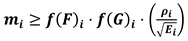
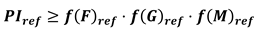
Design index (IDesign). The IDesign index coincides with the mass of the component. Mass calculation is carried out using performance indices provided by the Ashby theory [40] and based on load and stress type the component is subject to. As regards the definition of constraints and objectives, the goal for the case study considered is finding a solution which is strong and rigid, but at the same time provides the lowest possible mass. More specifically, the target is obtaining a component that does not yield under tensile loads, and resists torque bending loads. Additionally, it is essential that beyond withstanding loads, the bracket undergoes deformation as little as possible. The calculation of material property function provides inequalities which express the acceptability area for performance index and component mass, as reported in Equations 1 and 2.
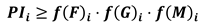
where PIi is the Performance Index of the i-th material, f(F)i are the functional requirements, f(G)i are the component geometric parameters, f(M)i are material properties.
For the design section, PIi turns out to be mi, the mass of the component made of the new material. Considering the specific case study of motor bracket, it provides tensile and compression loads: as a consequence, f(M)i turns out to be , which depends only on material type, as reported in Equation 2.
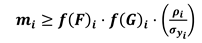
where is the material density [kg/m3] and is the material yield strength [MPa].
The same reasoning applies to component stiffness with the same nature of loads, leading to inequality in Equation 3:
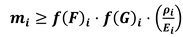
where Ei is the Young's modulus [GPa] of the new material.
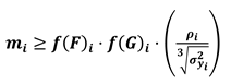
In case torque bending load are considered, the inequalities reported in Equations 2 and 3 become the following:
Objective functions must also hold for the component with the reference material. Rewriting the inequalities (1), (2), (3), (4), (5), the following relations are obtained.
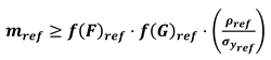
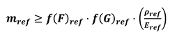
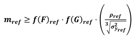
where the subscript “ref” (reference) is referred to the reference material.
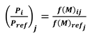
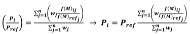
Once PIi and PIref are obtained, the method provides calculating the ratio (PIi/PIref), and using it to determine a unique value for PI referred to the new solution. To do this, the following assumptions are considered: f(F)i = f(F)ref and f(G)i = f(G)ref. This step involves evaluating and comparing Equation 6 with Equation 2, Equation 7 with Equation 3, Equation 8 with Equation 4, Equation 9 with Equation 5, and Equation 1 with Equation 10, from which the following equations are derived.
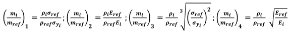
The first two equations consider tensional loads, while the other two equations consider torque bending load. Each of the four equations gives a different mass ratio depending on load type the material is subjected to, and therefore, four different mass values for the new component. To quantify a unique mass value, a weighted average is assumed as reported in Equations 13, 14 and 15.
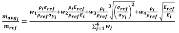
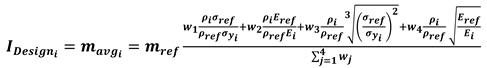
where is the mass of the lightweight component averaged based on different mass values derived from different PI ratios, while wj are the corresponding weights.
For example, if in a different case study with respect to the bracket component the tensile loads are considered more important than bending loads, weights w3 and w4 are lower than weights w1 and w2. On the contrary, in case material stiffness is assumed of lesser importance because the designer uses modification to component geometry to achieve greater stiffness, weights w2 and w4 are lower than weights w1 and w3. These corrective weights allow expanding the perimeter research of the new lightweight solutions
- without the need of considering the assumptions f(F)i = f(F)ref and f(G)i = f(G)ref
- setting parameters (PIi/PIref)j according to the needs of the specific case study.
Cost index (ICost). The cost index is defined to calculate the production cost of the component. ICost is defined as provided in Equation 16:

where k is the k-th industrial process, is the cost of raw material [€/kg], is the scrap fraction (fraction of primary material that ends up as sprues, risers, turnings, rejects or waste) [-], is the cost of tooling when it needs to be replaced [€], n is the batch size considered for the production of the component [-], is the tool life. It is the number of units that a set of tooling can produce before it has to be replaced [-], is the production rate of the k-th process [1/hr], is the Capital Cost of Equipment [€], is the Load factor, the fraction of time for which the equipment is productive [-], is the capital write-off time [years], d is the discount rate [-], is the overhead rate [€/hr].
Data characterizing both materials and industrial processes of the selected design solutions (mechanical, physical, economical, and environmental properties) are from the Granta Selector Database [64]. ICost is defined considering only the primary production process of the component, while it does not account for any secondary processes nor End-of-Life (EoL) treatments.
Environmental index (IEnv). The environmental index is defined to quantify the Climate Change (CC) effect (in kilograms of CO2_eq) due to the entire component Life Cycle (LC). The calculation of IENV is provided in Equation 17:
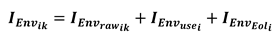
where quantifies the emissions due to raw materials acquisition considering also the increase in material quantity for primary process. is calculated through the following relation:

where is the CC due to extraction of 1 kg of the i-th material and it is taken from GrantaSelector [64].
, in Equation 17, assesses the CC caused by component use stage and it is quantified according to the following equation.
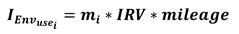
where mileage is the distance travelled during component operation [km] (assumed equal to vehicle use stage mileage) and IRV is the Impact Reduction Value, defined as the CC caused by the production of 1 kWh electricity consumed by the vehicle on which the component is mounted [kWh/100km100kg].
As provided in Table 1, the IRV coefficient depends on car mass (M), driving cycle, and grid mix assumed for electricity production.
For the motor bracket case study, the following boundary conditions are considered: 2 t car mass, 200000 km LC mileage, 28 European countries (EU28) grid mix for electricity production, and WLTP driving cycle for the operation stage. As regards EoL, the corresponding index () is calculated as follows:

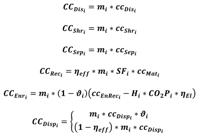
where is the CC of component disassembly [kgCO2_eq], is the CC of component shredding [kgCO2_eq], is the CC of materials separation after shredding [kgCO2_eq], is the CC credit achieved through recycling of separated materials [kgCO2_eq], is the CC credit achieved through incineration with energy recovery of separated materials [kgCO2_eq], is the CC of disposal phase of non-separated shredded materials [kgCO2_eq], is the mass-specific CC of disassembly step [kgCO2_eq/kg], is the mass-specific CC of shredding phase [kgCO2_eq/kg], is the mass-specific CC in Material stage [kgCO2_eq/kg], is the mass-specific CC of incineration with energy recovery [kgCO2_eq/kg], is the mass-specific CC of disposal phase [kgCO2_eq/kg], is the recycling substitution factor (quota of avoided primary production impact due to recycling) , is a factor that quantifies efficiency of separation in post-shredding phase, is the share of fibers in composite materials (applicable only for composite materials) , is the combustion heat in incineration with energy recovery (net value) [MJ/kg], is the specific CC of incineration with energy recovery [kgCO2_eq/MJ], is the efficiency of waste-to-energy plant .
Based on calculated values for IDesign, ICost, and IEnv, the method provides that VIKOR is applied to evaluate the above-mentioned indices and ranking the feasible design options based on pre-defined weighting criteria. After determining the pairwise matrix of dimensions mxn
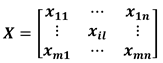
the next step is normalizing the matrix above. Considering [67], the pairwise matrix is normalized as follows:

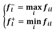
After this, the worst normalized value and the best normalized value need to be determined for all criteria. If the criterion is a beneficial attribute the following relations are considered:
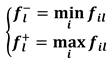
Otherwise, if the criterion is a cost attribute, the following relations are considered:
These values are used to calculate Si (group utility) and Ri (individual regret) with the following equations
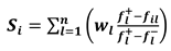
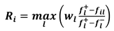
where are the weights respectively for design, cost and sustainability aspects defined as , and .
Finally, the single score Qi is calculated as follows:
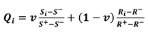
where v is a weight to support the maximum group utility strategy and varies between 0 and 1. Generally, it is assumed to be equal to 0.5 in the literature.
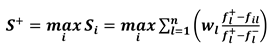
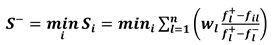
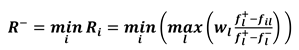
The values S+,S-,R+,R- are the defined as:

Then, the algorithm orders the alternatives in ascending order of the value of Qi : the smaller the value, the higher the ranking.
2.2. Case Study
This section deals with the validation of the conceived method by applying it to a practical case study taken from literature. As already mentioned before, the chosen application is the re-design of a motor bracket of a passenger C-segment electric car treated with by Celik et al. [68]. Table 2 reports the main technical features of the bracket component, which is chosen as reference design version for the implementation of materials selection method.
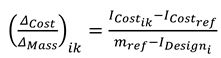
A first selection of materials applicable for lightweighting is carried out by considering the Ashby diagrams reported in Figure 1, which are built by means of the GrantaSelector software [64]. The diagrams show how materials are arranged within the database:
- the first one provides the ratio on the x-axis and the ratio on the y-axis, thus highlighting the ability of the material under tensile/compression loads to be light but at the same time rigid and strong (the lower the values, the better the material);
- the second one provides the ratio on the x-axis and the ratio on the y-axis, thus highlighting the ability of the material under torque bending loads to be light, but at the same time rigid and strong (the lower the values, the better the material).
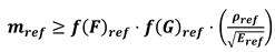
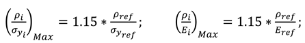
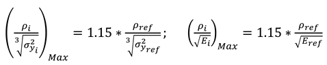
Taking into account the value of , , , in the baseline design version (bracket made of AISI 304 Stainless Steel), it is assumed that all materials which provide a maximum deterioration of indices of up to 15 % are considered as acceptable. The following equations provide the maximum acceptable value for indices above.
Due to functional features and operational conditions of the component, the following constraints are also assumed in the analysis: as the bracket is located close to an electric motor, a maximum operating temperature of 70 °C is considered, and the minimum yielding stress of the material is set at 170 MPa. Such a value is chosen based on [59], a redesign case study conducted on a similar application in terms of both component features and nature of the loads. Also, given the geometry and specifications of the bracket, only a part of the available processes in the Granta Database [53] are selected, that is only those compatible with component and materials considered. Since not all materials can be produced by means of all industrial processes (due to technological constraints, materials features, and geometric reasons), only specific processes are selected for the bracket case study (see Table 3).
The preliminary screening above provides 1151 materials. Considering the combination with industrial processes compatible with such materials, a set of 1850 possible design solutions (where a solution is intended as the association of base material with manufacturing technology) is obtained. Since the bracket equips a mass production car, a limitation is set on the increase in production cost of the lightweight alternative with respect to the baseline design. Such a limitation is defined through the coefficient expressed by Equation 33, that is the ratio between cost and mass variation due to lightweight design:
where and are the same of equation 15, is defined in equation 16 and is the value of considering the reference (AISI304 Stainless Steel and assumed the component is produced by Press Forming).
Thus, the total cost of the bracket is put in relation with the lightweight potential offered by the specific design alternative: negative values of are considered acceptable only if , while solutions which result in an increase of component mass () are discarded. As a consequence, only design options with a coefficientlower than the acceptable maximum value are compared and ranked through the VIKOR model: for the bracket component such acceptability maximum value is set to 10 Eur/kg. Regarding comparison and ranking of the selected 1850 solutions, the following considerations are made:
- parameters , , d, are those predefined by the Granta Selector software and they are assumed constant for each industrial process: , , d = 0.05, ;
- as the case study deals with a large-scale production electric vehicle, parameter n is set to 100000 units;
- it is assumed that the bracket component is manually disassembled, so the specific environmental impact of disassembly step (ccDis) is set to 0 [kgCO2_eq/kg];
- the specific impact of the shredding phase () is assumed constant for all materials selected, and it is considered an average value taking into account the shredding of the entire vehicle (0.0175 [kgCO2_eq/kg]), as provided by [65]. The same assumption is made for the disposal phase, for which is assumed 0.03 [kgCO2_eq/kg] (data from [69]);
- recycling is provided only for metals and metallic fibers. SF is considered constant for the same material, and it is assumed -0.25 for ferrous alloys and -0.15 for non-ferrous alloys. For other materials SF is assumed 0;
- is set to 0.98 for metal alloys, while for metallic fibers it is calculated as ;
- is provided by Granta Selector Database [64] for each material option explored;
- is set to 0.3;
- is derived from EcoInvent-APOS391 database considering the specific energy generation process “heat, district or industrial, natural gas | market for heat, district or industrial, natural gas/ heat and power co-generation, natural gas, conventional power plant” [70];
- since the case study deals with a large volume production component, it is chosen to give priority to the cost aspect, for which the corresponding index (ICost) is assumed to be four times more relevant than the other two indices (IDesign and IEnv). Consequently, the resulting weights for design, cost and sustainability aspects are respectively , , ;
- all three indices are considered “cost attributes”, so in the ranking performed through the VIKOR the lower the index value, the better the solution.
3. Results and discussion
Based on acceptability criteria and parameters setting described in the previous section, the number of design solutions (combination of materials and manufacturing processes) which result to be a viable option for the bracket component is 1316, which are ranked in order of preference through the VIKOR method. Table 3 shows the ranking of the first 20 lightweight options, for each of which the following parameters are reported:
- -
- component mass (corresponding to , as provided by Equation 15);
- -
- cost of raw materials (corresponding to *, as provided by Equation 16);
- -
- total component cost (, as provided by Equation 16);
- -
- cost variation in relation to weight reduction (corresponding to coefficient , as provided by Equation 33);
- -
- environmental impact of component use stage (, as provided by Equation 19);
- -
- environmental impact of entire component LC (, as provided by Equation 17);
- -
- single score , based on which the VIKOR provides the ranking.
The first discussion point is represented by the fact that negative values of correspond to an alternative with potential for cost saving, that is a solution which provides lightweighting and at the same time cost reduction. As regards the ranking of the selected lightweight options, wrought steels are placed in the top positions (from the first to the sixth), and all of these are produced through press forming as primary manufacturing process. The reason for which steels rank so high is that, despite the lower mechanical strength with respect to other materials in the ranking (such as plastic matrix composites or metal matrix composites) and the consequent smaller weight reduction offered, it is definitely more economical (1.40 €/kg raw material cost for steel, against 3.30 €/kg raw material cost for aluminum).

Table 3.
Results of materials selection: ranking of the first 20 lightweight options (only materials with a less than 10 Eur/kg and criteria weights , , )
Table 3.
Results of materials selection: ranking of the first 20 lightweight options (only materials with a less than 10 Eur/kg and criteria weights , , )
| Ranking | Design solution | Mass [kg] | Cost | CC [kgCO2_eq] | Qi | |||
|---|---|---|---|---|---|---|---|---|
| Raw Material [Eur] |
Total [Eur] |
[Eur/kg] | Use | Total LC | ||||
| Ref: Stainless steel austenitic AISI 304 annealed–Press Forming | REF: 8.91 | REF: 50 | REF: 54 | REF: 49 | REF: 105 | |||
| 1 | Low alloy steel, AISI 9255, oil quenched & tempered at 205°C - Press Forming | 4.98 | 9 | 13 | -14 | 27.6 | 40 | 0.0149 |
| 2 | Low alloy steel, AISI 5160, oil quenched & tempered at 205°C - Press Forming | 5.10 | 9 | 13 | -14 | 28.3 | 41 | 0.0195 |
| 3 | Low alloy steel, AISI 4140, oil quenched & tempered at 205°C - Press Forming | 5.12 | 10 | 14 | -14 | 28.4 | 42 | 0.0211 |
| 4 | Low alloy steel, AISI 8650, oil quenched & tempered at 205°C - Press Forming | 5.12 | 11 | 14 | -14 | 28.4 | 42 | 0.0225 |
| 5 | Carbon steel, AISI 1340, oil quenched & tempered at 205°C - Press Forming | 5.22 | 9 | 13 | -15 | 29 | 42 | 0.0242 |
| 6 | Low alloy steel, AISI 6150, oil quenched & tempered at 205°C - Press Forming | 5.25 | 10 | 13 | -11 | 28.8 | 49 | 0.0268 |
| 7 | Cast-iron, austempered ductile, ADI 1600 - Green Sand casting, automated | 5.65 | 4 | 6 | -15 | 31.3 | 50 | 0.0340 |
| 8 | Stainless steel, martensitic, AISI 440C, tempered at 316°C - Binder Jetting | 5.17 | 10 | 18 | -10 | 28.7 | 46 | 0.0352 |
| 9 | Press hardening steel, 22MnB5, austenized & H20 quenched, coated - Press Forming | 5.51 | 10 | 14 | -12 | 30.6 | 49 | 0.0396 |
| 10 | Aluminum, 5182, H19 - Press Forming | 4.34 | 19 | 22 | -7 | 24.1 | 91 | 0.0436 |
| 11 | Aluminum, 2024, T8510/T8511 - Press Forming | 4.31 | 20 | 23 | -7 | 23.3 | 88 | 0.0436 |
| 12 | Martensitic steel, YS1200, hot rolled - Press Forming | 5.59 | 12 | 16 | -11 | 31 | 52 | 0.0483 |
| 13 | Cast-iron, nodular graphite, EN GJS 900 2, hardened & tempered - Green Sand casting, automated | 6.07 | 4 | 6 | -17 | 33.7 | 53 | 0.0592 |
| 14 | Aluminum, A332.0, cast, T6 - Squeeze casting | 4.66 | 19 | 26 | -7 | 25.8 | 80 | 0.0592 |
| 15 | Aluminum, 6111, T62 - Press Forming | 4.68 | 20 | 24 | -7 | 26 | 96 | 0.0615 |
| 16 | Stainless steel, martensitic, ASTM CA-40, cast, tempered at 315°C - Green Sand casting, automated | 5.45 | 20 | 22 | -9 | 30.3 | 61 | 0.0633 |
| 17 | Low alloy steel, 24CrMo13-6, quenched & tempered - Press Forming | 5.96 | 13 | 16 | -13 | 33 | 54 | 0.0650 |
| 18 | Duralcan Al-20SiC (p) cast (F3K20S) - Squeeze casting | 3.81 | 28 | 34 | -4 | 21.1 | 70 | 0.0691 |
| 19 | Dual phase steel, YS600, cold rolled - Press Forming | 6.15 | 12 | 15 | -14 | 34.1 | 56 | 0.0716 |
| 20 | Aluminum, 3004, H38 - Press Forming | 4.94 | 21 | 24 | -7 | 27.4 | 102 | 0.0771 |
As regards the ranking of materials obtained, in the first position it is found a low alloyed steel (low alloy steel, AISI 9255, oil quenched & tempered at 205°C), manufactured through press forming. The comparison of such a lightweight option with the baseline (press formed AISI304 stainless steel) stresses a mass decrease of around 44 %, a 75 % cost saving, and CC reduction of around 60 %. The following three positions (from the 2nd to the 4th) also provide low alloy steels, which provide very similar savings for all the assessment criteria considered: mass reduction in the range 5.10 - 5.12 kg, cost decrease in the range 13 - 14 €, CC impact abatement in the range 41 - 42 kgCO2_eq. Among low alloy steel solutions, the fifth position is occupied by an alternative based on carbon steel, which involves a good lightweight potential (mass of lightweight component of 5.22 kg) due to mechanical properties comparable with the first position design (see Table 4), and also remarkable cost and CC saving (respectively 75 % and 53 %).
The seventh position provides a cast-iron (ADI 1600 austempered ductile) alternative produced by the green sand-casting automated process. Cast materials have in general lower mechanical properties than wrought materials: this involves a lower mass decrease for the cast-iron bracket to withstand the loads the component is subjected to (5.65 kg). That said, cost and CC reduction result to be very high, respectively 89 % and 52 %. The reason for the definitely strong cost reduction is the very low cost of raw material (0.44 €/kg). Another design alternative made of cast-iron is found in 13th position (nodular graphite, EN GJS 900 2, hardened and tempered), which is down in the ranking mainly because of the bigger mass despite the low cost of material acquisition. In 8th position the ranking provides a martensitic stainless-steel component (AISI 440C tempered at 316°C) produced through additive manufacturing binder jetting, that guarantees a 42 % mass saving. Despite cost reduction is very high (66 %), such a solution is the worst within the steel design options in the top 20 positions: this is due to the high cost of the additive manufacturing technology, which amounts to 8 € to produce a bracket of 5.17 kg. In 9th and in 12th positions the ranking provides respectively press hardening steel 22MnB5, and martensitic steel YS1200, both manufactured through the press forming process. These materials, typically used for crash management components, show worst mechanical properties than the low alloy-steels (as reported in Table 4), so the corresponding component mass results higher (around 5.5 kg for both alternatives), and this is reflected in little bigger cost and CC (14 € and 16 €; 49 kgCO2_eq and 52 kgCO2_eq).
Going down in the ranking, the classification provides five aluminium solutions: pressed formed 5182 aluminium - H19 (in 10th position), pressed formed 2024 aluminium - T8510/T8511 (in 11th position), squeeze cast A332.0 aluminium (in 14th position), pressed formed 6111 aluminium - T62 (in 15th position), and pressed formed 3004 aluminum - H38 (in 20th position). In general, it can be said that the use of aluminium allows achieving a bigger mass saving than the steel design options (in the range 44 - 52 %). That said, when evaluating the economical aspect, the very high costs of raw materials acquisition (definitely bigger than steels, see Table 4) partially counterbalance the low component mass, leading however to cost savings that remain very important (in the range 52 - 59 %). On the other hand, the high environmental impact due to the strong energy intensity of aluminium extraction and production makes that the CC saving is relatively limited, from a maximum of 80 kgCO2_eq for A332.0 T6 aluminium produced through squeeze casting (position n°14 in the ranking), up to an almost null reduction (3 kgCO2_eq) for press formed 3004 H38 aluminium (position n°20 in the ranking). As a confirmation, Table 3 shows a big difference in the CC between use and entire LC, meaning that the vast majority of the environmental impact is concentrated in the materials acquisition stage.
Passing to last positions, Duralcan Al-20SiC design processed by squeeze casting is found in 18th. The strength of this kind of material is the lightweight potential, which is comparable with low alloy steels (57 % mass saving), while considering cost and CC the overall reduction is around 35 %. Such an outcome is in line with literature review presented in the introduction section, stressing that high-performance materials are often discarded for high production volumes because of their notable manufacturing costs, which make those not sustainable for mass-market production.
Another design option for which similar considerations can be done is PolyAmide 66 (PA66) with 40 % long carbon fibers produced by compression molding, that ranks 35th (out of the list of top 20 design alternatives but however worthy to be mentioned). Although such a solution allows achieving a great mass saving (3.71 kg, resulting in more than 58 % reduction with respect to the reference), the main motivation for the low ranking is represented by the increase in both costs and environmental impact. Indeed, the PA66 bracket requires 69 € for its production (27 % growth), while the CC amounts to even 161 kgCO2_eq, thus proving a 53 % increase with respect to the reference.
Another relevant discussion point is the strong variability in indices among design options in the ranking. In this regard, Figure 2 provides IDesign, ICost and ICC for the best 20 solutions in terms of ratio with respect to the baseline design, allowing to evaluate how design solutions perform towards different aspects considered.
As shown in the diagram, for the first five design alternatives, all three indices are more or less aligned on the same values. This is mainly due to the fact that the base material and manufacturing process remain substantially the same (low alloy steel and press forming), with variations in mechanical properties (reported in Table 4) due to different chemical composition not involving relevant discrepancies in terms of final component mass (variability range: 4.98 - 5.22 kg).
As regards aluminium materials (both alloys and aluminium-based matrices), Figure 2 shows that they are generally characterized by lower values of the design index ratio than low alloy steels (in the range 0.42 - 0.55), while cost and environmantal indices ratios result to be definitely bigger (in the range 0.41 - 0.62). Such an outcome can be explained by the strong energy consumption of extraction and refinement processes of the allumina mineral, which on the one hand causes a strong economical expenditure, and on the other hand involves high green-house gas emissions for producing the amount of consumed energy. Differently, solutions based on martensitic, dual-phase steels and press hardening lightweight design options provide similar (or slighlty higher) design index ratio than low alloy steels, but cost and environmantal indices ratios are bigger, these latter being the main cause for backward ranking. Finally, it has to be noted that cast-iron solutions (positioned in 7th and 13th positions) present constrasting results with respect to above-mentioned design alternatives. Indeed, against decisely worst performances in terms of lightweight potential and environmental effects than low alloy steels, they provide very low cost of primary material (cost index ratio below 0.13), which involves a mid-table positioning in the ranking of the best 20 solutions.
The main innovation of the conceived approach for materials selection is represented by the integration of the Ashby and VIKOR method, which allows performing design choices evaluating at the same time different and often conflicting design aspects. This represents a significant innovation in material selection methodology, bridging the gap between traditional selection processes and the urgent need for sustainable development in automotive engineering. In the light of holistic perspective above-mentioned, the refined method represents a valuable tool to be applied in the first phases of the re-design process when the target is lightening an automotive component.
As regards future development of the work, topological optimization represents a viable strategy to define optimized design for the component, to achieve an extra weight reduction in addition to the one obtained by change in material and manufacturing process; this further mass reduction would consequently provide advantages under both cost and sustainability point of view.
5. Conclusions
The paper conceives a method for materials selection when re-designing an automotive component in a lightweight eco-design perspective. The strength of the refined method is considering at the same time the three major pillars of the design process: structural integrity, cost sustainability, and environmental sustainability, this latter assessed by means of the CC impact category. The development of the method is based on Ashby theory indices, which are used to define design indicators customized according to load and stress features of the specific case study. Cost and environmental aspects are evaluated by means of innovative indices, which enable assessing the most relevant phases within LC of the considered car part. The design solutions (intended as combination of component base material and primary manufacturing process) are ranked by a single score indicator calculated through the VIKOR MCDA model, that provides also weighting of considered aspects according to peculiarities of the specific case study. Based on such a ranking resulting from the assessment of multiple and concurring aspects, a wise and conscious selection of the optimal design solutions can be carried out.
The conceived method is validated through the application to a practical case study from literature, a motor bracket mounted on an electric passenger car, which in the reference design version is made of AISI 304 produced through press forming. Considering industrial processes compatible with chosen material options, the method provides 1850 possible alternatives. The constitutive equations of the model are applied to the case study, obtaining the selection of 1151 materials which are characterized on the basis of data from the GrantaSelector database. As regards criteria weighting, ICost is assumed to be four times more relevant than the design and environmental indices, and a first screening of acceptable design options is made by assuming a limit to cost increase of lightweight solutions by means of the parameter (cost increase against mass reduction). Results stress that a bracket made of low alloy steel (AISI 9255) processed through press forming is identified as the optimal solution in replacement of the stainless-steel baseline component. Such a design alternative allows achieving very high saving at component level, both in terms of weight (44 % decrease), cost (75 % decrease), and CC effect (61 % decrease). Other lightweight options providing notable improvement under selection criteria considered are based on aluminium, martensitic steels, dual-phase steels and cast-iron materials.
As regards future developments of the work, the application of topological optimization represents an interesting option to explore further margins of lightweighting for the selected design solutions, thus achieving an extra reduction in terms of both cost and environmental impact.
References
- IEA. CO2 Emissions in 2022. IEA 2023, Paris.
- Ferreira, V.; et al. Technical and environmental evaluation of a new high performance material based on magnesium alloy reinforced with submicrometre-sized TiC particles to develop automotive lightweight components and make transport sector more sustainabl. J. Mater. Res. Technol. 2019, 8, 2549–2564. [Google Scholar] [CrossRef]
- Commission European. White Paper: Roadmap to a Single European Transport Area—Towards a Competitive and Resource Efficient Transport System. European Commission: Brussels, Belgium. 2011, /* COM/2011/0144 final */.
- Brooke, L.; Evans, H. Lighten up! Automot. Eng. 2009, 117, 16–22. [Google Scholar]
- Goede, M. Super Light Car—Lightweight construction thanks to a multi-material design and function integration. Eur. Transp. Res. Rev. 2009, 1, 5–10. [Google Scholar] [CrossRef]
- Ferreira, V.; et al. Lightweight automotive components based on nano-diamond-reinforced aluminium alloy: A technical and environmental evaluation. Diam. Relat. Mater 2019, 92, 174–186. [Google Scholar] [CrossRef]
- Kelly, J.C.; Sullivan, J.L.; Burnham, A.; Elgowainy, A. Impacts of vehicle weight reduction via material substitution on life-cycle greenhouse gas emissions. Environ. Sci. Technol 2015, 49, 12535–12542. [Google Scholar] [CrossRef]
- Jaguar Land Rover Using Aerospace Technology to Develop Future Lightweight Vehicles. https://media.jaguarlandrover.com/news/2020/10/jaguar-land-rover-using-aerospace-technology-develop-future-lightweight-vehicles. 22 October 2020.
- The lightweight New A8 - Unique mix of materials used in the next Audi milestone. https://press.audi.co.uk/en-gb/releases/52#:~:text=Picture%20caption,A8%20for%20the%20first%20time. 5 April 2017.
- Stellantis Fosters Circular Economy Ambitions with Dedicated Business Unit to Power New Era of Sustainable Manufacturing and Consumption. https://www.stellantis.com/en/news/press-releases/2022/october/stellantis-fosters-circular-economy-ambitions-with-dedicated-business-unit-to-power-new-era-of-sustainable-manufacturing-and-consumption. 11 October 2022.
- Koffler, C.; Rohde-Brandenburger, K. On the Calculation of Fuel Savings Through Lightweight Design in Automotive Life Cycle Assessments. Int. J. Life Cycle Assess. 2010, 15, 128–135. [Google Scholar] [CrossRef]
- Kim, H.C.; Wallington, T.J. Life Cycle Assessment of Vehicle Lightweight-ing: A Physics-Based Model to Estimate Use-Phase Fuel Consumption of Electrified Vehicles. Environ. Sci. Technol. 2016, 50, 11226–11233. [Google Scholar] [CrossRef]
- Kroll, L.; et al. Lightweight Components for Energy-Efficient Machine Tools. CIRP J. Manuf. Sci. Technol. 2011, 4, 148–160. [Google Scholar] [CrossRef]
- Neugebauer, R.; et al. Structure Principles of Energy Efficient Machine Tools. CIRP J. Manuf. Sci. Technol. 2011, 4, 136–147. [Google Scholar] [CrossRef]
- Zhang, W.; Xu, J. Advanced lightweight materials for Automobiles: A review. Materials & Design 2022, 221. [Google Scholar] [CrossRef]
- Mascarin, A.; Hannibal, T.; Raghunathan, A.; Ivanic, Z.; Francfort, J. Vehicle Lightweighting: 40% and 45% Weight Savings Analysis: Technical Cost Modeling for Vehicle Lightweighting. United States: N. p.: S.n., 2015.
- Tisza, M.; Czinege, I. Comparative study of the application of steels and aluminium in lightweight production of automotive parts. Int. J. Lightweight Mater. Manuf. 2018, 1, 229–238. [Google Scholar] [CrossRef]
- Mallick, P.K. Materials, Design and Manufacturing for Lightweight Vehicles, 2nd edition, 2020.
- Kumar, D.; Kumar, R.P.; Thakur, L. A review on environment friendly and lightweight Magnesium-Based metal matrix composites and alloys. Materials Today Proceedings 2021, 38, 359–364. [Google Scholar] [CrossRef]
- Galán, J.; et al. Advanced high strength steels for automotive industry. Revista de metalurgia 2012, 48, 118. [Google Scholar] [CrossRef]
- Wazeer, A.; Das, A.; Abeykoon, C.; Sinha, A.; Karmakar, A. Composites for electric vehicles and automotive sector: A review. Green Energy and Intelligent Transportation 2023, 2. [Google Scholar] [CrossRef]
- Bourmaud, A.; Fazzini, M.; Renouard, N.; Behlouli, K.; Ouagne, P. Innovating routes for the reused of PP-flax and PP-glass non woven composites: A comparative study. Polymer Degradation and Stability 2018, 152, 259–271. [Google Scholar] [CrossRef]
- Elmarakbi, A.; Azoti, W. State of the Art on Graphene Lightweighting Nanocomposites for Automotive Applications. Experimental Characterization, Predictive Mechanical and Thermal Modeling of Nanostructures and their Polymer Composite; Marotti de Sciarra, F., Russo, P., 2018, 1-23.
- La Rosa, A.D.; et al. ; Biobased versus traditional polymer composites. A life cycle assessment perspective. J. Clean. Prod. 2014, 74, 135–144. [Google Scholar]
- Schönemann, M.; Schmidt, C.; Herrmann, C.; Thiede, S. Multi-level modeling and simulation of manufacturing systems for lightweight automotive components. Procedia CIRP 2016, 41, 1049–1054. [Google Scholar] [CrossRef]
- Iadicola, M.A.; Creuziger, A.A.; Luecke, W.E.; Banerjee, D.K.; Gnaupel-Herold, T.H. Automotive Lightweighting. NIST, 2008. Available online: https://www.nist.gov/programs-projects/automotive-lightweighting (accessed on 22 October 2020).
- Priarone, P.C.; Catalano, A.R.; Settineri, L. Additive manufacturing for the automotive industry: On the life-cycle environmental implications of material substitution and lightweighting through re-design. Prog. Addit. Manuf. 2023, 8, 1229–1240. [Google Scholar] [CrossRef]
- Dattilo, C.A.; Zanchi, L.; Del Pero, F.; Delogu, M. Sustainable design: An integrated approach for lightweighting components in the automotive sector. SDM-2017: 4th International Conference on Sustainable Design and Manufacturing, 2017.
- Simoes, C.L.; Figueiredo de Sà, R.; Ribeiro, C.J.; Bernardo, P.; Pontes, A.J.; Bernardo, C.A. Environmental and economic performance of a car component: Assessing new materials, processes and designs. J. Clean. Prod. 2016, 118, 105–117. [Google Scholar] [CrossRef]
- Delogu, M.; Zanchi, L.; Maltese, S.; Bonoli, A.; Pierini, M. Environmental and economic life cycle assessment of a lightweight solution for an automotive component: A comparison between talc-filled and hollow glass microspheres-reinforced polymer composites. J. Clean. Prod. 2016, 139, 548–560. [Google Scholar] [CrossRef]
- Vita, A.; Castorani, V.; Germani, M.; Marconi, M. Comparative life cycle assessment of low-pressure RTM, compression RTM and high-pressure RTM manufacturing processes to produce CFRP car hoods. Procedia CIRP 2019, 80, 352–357. [Google Scholar] [CrossRef]
- Zanchi, L.; Delogu, M.; Ierides, M.; Vasiliadis, H. Life cycle assessment and life cycle costing as supporting tools for EVs lightweight design. Sustain. Des. Manuf. 2016, 52, 335–348. [Google Scholar]
- Fiebig, S.; Sellschopp, J.; Manz, H.; Vietor, T.; Axmann, J.K.; Schumacher, A. Future challenges for topology optimization for the usage in automotive lightweight design technologies. 11th World Congress on Structural and Multidisciplinary Optimisation, Sydney, Australia, June 2015.
- Işık, M.; et al. Topology optimization and manufacturing of engine bracket using electron beam melting. J. Addit. Manuf. Technol. 2021, 1, 583. [Google Scholar]
- Puri, P.; Compston, P.; Pantano, V. Life Cycle assessment of Australian automotive door skins. Int. J. Life Cycle Assess. 2009, 14, 420–428. [Google Scholar] [CrossRef]
- Delogu, M.; Del Pero, F.; Romoli, F.; Pierini, M. Life cycle assessment of a plastic air intake manifold. Int. J. Life Cycle Assess. 2015, 20, 1429–1443. [Google Scholar] [CrossRef]
- Poulikidou, S.; Jerpdal, L.; Björklund, A.; Åkermo, M. Environmental performance of self-reinforced composites in automotive applications. Case study on a heavy truck component. Mater. Des. 2016, 103, 321–329. [Google Scholar] [CrossRef]
- Inti, S.; Sharma, M.; Tandon, V. An approach for performing life cycle impact assessment of pavements for evaluating alternative pavement designs. Int. Conf. on Sust. Des. Eng. and Const 2016, 145, 964–971. [Google Scholar] [CrossRef]
- Mayyas, A.T.; Qattawi, A.; Mayyas, A.R.; Omar, M.A. Life cycle assessment-based selection for a sustainable lightweight body-in-white design. Energy 2012, 39, 412–425. [Google Scholar] [CrossRef]
- Ashby, M.F.; Johnson, K. Materials and Design: The Art and Science of Material Selection in Product Design, 2nd ed.; Butterworth-Heinemann: Oxford, UK, 2013.
- Camargo, D.Z.; et al. Selection of Materials for Weight Reduction in Sports Cars. Adv. Mater. Res. 2019, 1152, 73–82. [Google Scholar] [CrossRef]
- Ashby, F. Multi-Objective Optimization in Material Design and Selection. Acta Mater. 2000, 48, 359–369. [Google Scholar] [CrossRef]
- Lewis, G.M.; et al. Green Principles for Vehicle Lightweighting. Environ. Sci. Technol. 2019, 53, 4063–4077. [Google Scholar] [CrossRef] [PubMed]
- Rao, R.V.; Patel, B.K. A subjective and objective integrated multiple attribute decision making method. Mater. Des. 2010, 37, 4738–4747. [Google Scholar] [CrossRef]
- Stojčić, M.; et al. Application of MCDM Methods in Sustainability Engineering: A Literature Review 2008–2018. Symmetry 2019, 11, 3. [Google Scholar] [CrossRef]
- Hwang, C.L.; Yoon, K. Methods for Multiple Attribute Decision Making. In: Multiple Attribute Decision Making. Lecture Notes in Economics and Mathematical Systems, vol. 186. Springer, Berlin, Heidelberg, 1981.
- Opricovic, S. Multicriteria optimization of civil engineering systems. Faculty of Civil Engineering: Belgrade, Serbia, 1998; pp. 5–21.
- Chatterjee, P.; Chakraborty, S. A comparative analysis of VIKOR method and its variants. Decis. Sci. Lett. 2016, 5, 469–486. [Google Scholar] [CrossRef]
- Zavadskas, E.K.; Kaklauskas, A.; Šarka, S. The new method of multicriteria evaluation of projects. Tech. and Economic Dev. of Ec. 1996, 1, 131–139. [Google Scholar]
- Mousavi-Nasab, S.H.; Sotoudeh-Anvari, A. A comprehensive MCDM-based approach using TOPSIS, COPRAS, and DEA as an auxiliary tool for material selection problems. Mater. Des. 2017, 121, 237–253. [Google Scholar] [CrossRef]
- Brans, J.P.; Nadeau, R.; Landry, M. L’ingénierie de la décision. Elaboration d’instruments d’aide à la décision. La méthode PROMETHEE. In: L’Aide à la Décision: Nature, Instruments et Perspectives d’Avenir, 1982, pp.183-213.
- Brans, J.P.; De Smet, Y. PROMETHEE Methods. In: Greco, S.; Ehrgott, M.; Figueira, J. (eds) Multiple Criteria Decision Analysis. International Series in Operations Research & Management Science, vol. 233. Springer, New York, NY, 2016.
- Roy, B. Classement et choix en présence de points de vue multiples. Rev. Fr. Inf. Rech. Opér. 1968, 2, 57–75. [Google Scholar] [CrossRef]
- Figueira, J.R.; Mousseau, V.; Roy, B. ELECTRE Methods. In: Greco, S.; Ehrgott, M.; Figueira, J. (eds) Multiple Criteria Decision Analysis. International Series in Operations Research & Management Science, vol. 233. Springer, New York, NY, 2016.
- Brauers, W.K.M. Optimization Methods for a Stakeholder Society. A Revolution in Economic Thinking by Multiobjective Optimization. Kluwer Academic Publishers, Boston, 2004.
- Chakraborty, S. Applications of the MOORA method for decision making in manufacturing environment. Int. J. Adv. Manuf. Technol. 2011, 54, 1155–1166. [Google Scholar] [CrossRef]
- Kumar, R.; Ray, A. Selection of material for optimal design using multi-criteria decision making. Procedia Mater. Sci. 2014, 6, 590–596. [Google Scholar] [CrossRef]
- Giorgetti, A.; Cavallini, C.; Arcidiacono, G.; Citti, P. A mixed C-VIKOR fuzzy approach for material selection during design phase: A case study in valve seats for high performance engine. Int. J. Appl. Eng. Res. 2017, 12, 3117–3129. [Google Scholar]
- Jahan, A.; Mustapha, F.; Ismail, M.; Sapuan, S.; Bahraminasab, M. A comprehensive VIKOR method for material selection. Mater. Des. 2011, 32, 1215–1221. [Google Scholar] [CrossRef]
- Manalo, M.V.; Magdaluyo, E.R. Integrated DLM-COPRAS method in material selection of laminated glass interlayer for a fuel-efficient concept vehicle. World Congress on Engineering, London, UK, 2018; Vol. 2.
- Gul, M.; Celik, E.; Gumus, A.; Guneri, A. A fuzzy logic based PROMETHEE method for material selection problems. Beni-Suef Univ. J. Basic Appl. Sci. 2018, 7, 68–79. [Google Scholar] [CrossRef]
- Aziz, C.; Taleb, M.; Zakia, R.; Rajaa, B.; El Haji, M. Electre multicriteria analysis for choosing material concerned by the corrosion problem. J. Appl. Sci. Environ. Stud. 2020, 3, 132–146. [Google Scholar]
- Sen, B.; Bhattacharjee, P.; Mandal, U. A comparative study of some prominent multi criteria decision making methods for connecting rod material selection. Perspect. Sci. 2016, 8, 547–549. [Google Scholar] [CrossRef]
- ANSYS. Available online: https://www.ansys.com/it-it/products/materials/granta-selector (accessed on 17 July 2024).
- Del Pero, F.; Berzi, L.; Antonacci, A.; Delogu, M. Automotive Lightweight Design: Simulation Modeling of Mass-Related Consumption for Electric Vehicles. Machines 2020, 8, 3. [Google Scholar] [CrossRef]
- Antonacci, A.; Del Pero, F.; Baldanzini, N.; Delogu, M. Holistic eco-design tool within automotive field. IOP Conf. Ser. Mater. Sci. Eng. 2022, 1214. [Google Scholar] [CrossRef]
- Więckowski, J.; Sałabun, W. How the normalization of the decision matrix influences the results in the VIKOR method? Procedia Comput. Sci. 2020, 176, 2222–2231. [Google Scholar] [CrossRef]
- Celik, H.K.; et al. Strength-Based Design Analysis of a Damaged Engine Mounting Bracket Designed for a Commercial Electric Vehicle. J. Fail. Anal. Prev. 2021, 21, 1315–1322. [Google Scholar] [CrossRef]
- Del Pero, F.; Berzi, L.; Dattilo, C.A.; Delogu, M. Environmental sustainability analysis of Formula-E electric motor. Proc. Inst. Mech. Eng. Part D J. Automob. Eng. 2021, 235, 303–332. [Google Scholar] [CrossRef]
- Ecoinvent. Available online: https://ecoinvent.org/ (accessed on 17 July 2024).
Figure 1.
Ashby diagrams used for material selection: ferrous metal alloys are represented in green, non-ferrous metal alloys in purple and red, plastics in blue, and composite materials with both plastic and metal matrices in brown and orange. The black lines are the maximum deterioration of parameters [53].
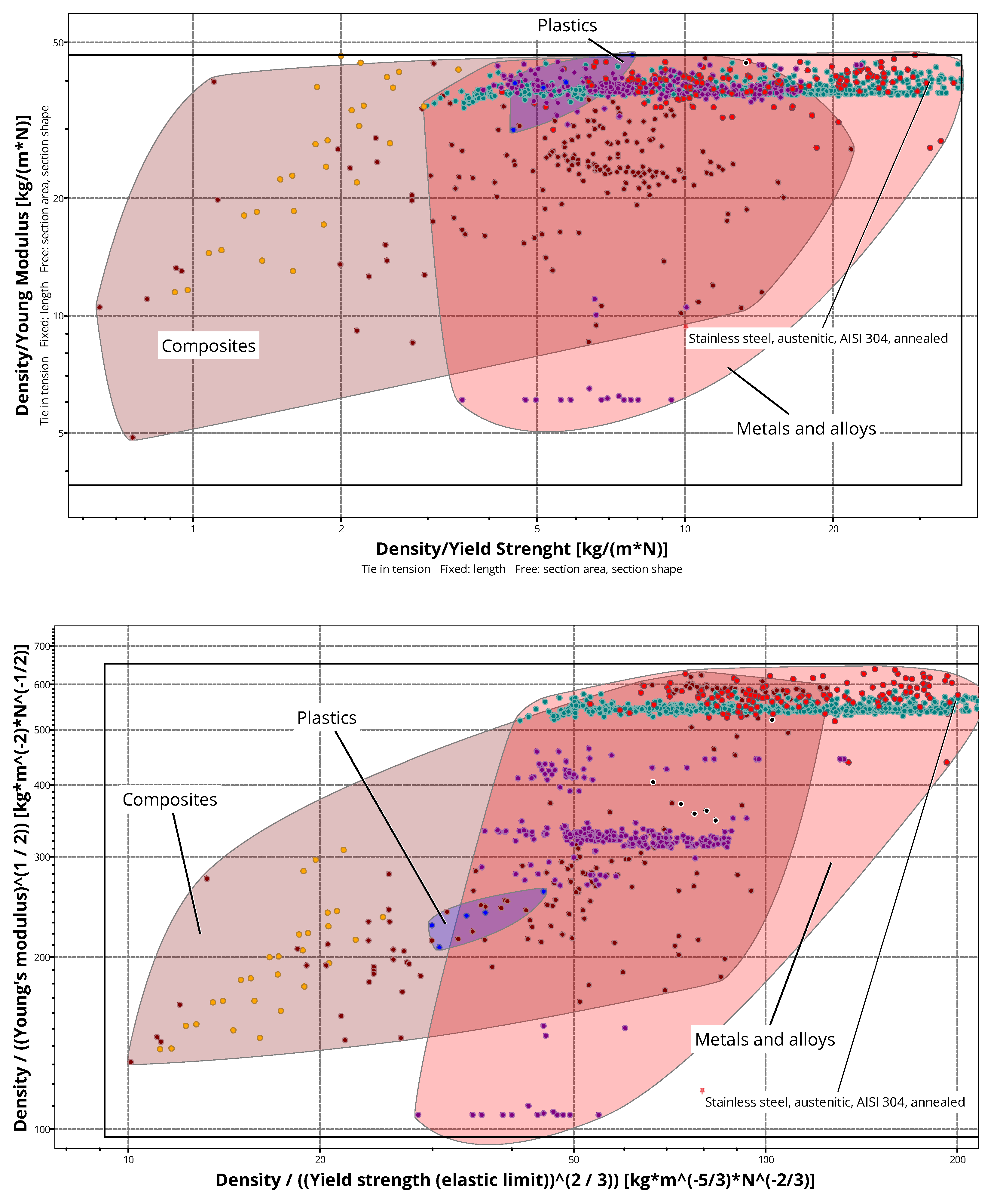
Figure 2.
Design, cost and environmental indices in relation to baseline design.
Table 1.
IRV coefficient calculated by geographical relevance (NO: Norway, EU28: 28-country European average, PL: Poland) and standard driving cycle (NEDC: New European Driving Cycle, WLTC: Worldwide harmonized Light vehicles Test Cycles, ALDC: All-Long Driving Cycle) [65,66].
| IRV (kgCO2_eq/(100km*100kg)) | |||
| NEDC | WLTP | ALDC | |
| NO | IRVNO_NEDC = 3.0*10-6M+0.0116 | IRVNO_WLT P = 4.0*10-6M+0.0121 | IRVNO_WLTP = 4.0*10-6M+0.0121 |
| EU28 | IRVEU28_NEDC = 4.7*10-5 M+0.1591 | IRVEU28_WLTP = 5.6*10-5 M+0.1655 | IRVEU28_ALDC = 1.2*10-4M+0.2231 |
| PL | IRVPL_NEDC = 1.1*10-4 M+0.3798 | IRVPL_WLTP = 1.3*10-4 M+0.3951 | IRVPL_ALDC = 2.8*10-4 M+0.5326 |
Table 2.
Main technical features of bracket component in the reference design version (data from [68]).
Table 2.
Main technical features of bracket component in the reference design version (data from [68]).
| Motor Mounting Bracket component | |
| Material | AISI304 Stainless Steel |
| Mass | 8.913 [kg] |
| Max Torque without yielding | 3x10 ^5 [N/mm] |
| Max Displacement | 0.284 [mm] |
| Max Equivalent Stress | 170 [MPa] |
Table 3.
Manufacturing processes selected for the case study (data provided by Granta Selector Database [64]).
Table 3.
Manufacturing processes selected for the case study (data provided by Granta Selector Database [64]).
| Industrial Processes | |||||
|---|---|---|---|---|---|
| Binder Jetting | 0.98 | 0.05 | 316000 | 22.40 | 361000 |
| Squeeze casting | 0.93 | 22200 | 22400 | 30.00 | 393000 |
| Gravity die casting | 0.69 | 10500 | 31600 | 15.80 | 35200 |
| Investment casting, automated (Lost Wax Process) | 0.82 | 6810 | 1580 | 44.70 | 39300 |
| Evaporative pattern casting, automated | 0.49 | 2980 | 7071 | 31.62 | 23086 |
| Shell Casting | 0.49 | 3930 | 3160 | 15.81 | 5560 |
| Ferro die Casting | 0.80 | 44500 | 7070 | 54.80 | 393000 |
| Green Sand casting, automated | 0.63 | 2150 | 31600 | 77.50 | 39300 |
| Replicast casting | 0.69 | 5560 | 3160 | 22.40 | 21500 |
| Press Forming | 0.75 | 78600 | 100000 | 77.50 | 278000 |
| Cold Isostatic Pressing (CIP) | 0.99 | 1470 | 316 | 31.60 | 141000 |
Table 4.
Material properties of the top 20 design solutions.
| Material | Price Raw Material [Eur/kg] | Density [kg/m3] | Young Modulus [GPa] | Yield Strength [MPa] | Primary production CC (virgin grade) [kg/kg] |
| Ref: Stainless steel austenitic AISI 304 annealed | 5.29 | 7850 | 196 | 252 | 5.73 |
| Low alloy steel, AISI 9255, oil quenched & tempered at 205°C | 1.38 | 7850 | 211 | 2040 | 2.33 |
| Low alloy steel, AISI 5160, oil quenched & tempered at 205°C | 1.36 | 7850 | 209 | 1780 | 2.33 |
| Low alloy steel, AISI 4140, oil quenched & tempered at 205°C | 1.44 | 7850 | 212 | 1630 | 2.33 |
| Low alloy steel, AISI 8650, oil quenched & tempered at 205°C | 1.56 | 7850 | 211 | 1660 | 2.33 |
| Carbon steel, AISI 1340, oil quenched & tempered at 205°C | 1.36 | 7850 | 207 | 1580 | 2.33 |
| Low alloy steel, AISI 6150, oil quenched & tempered at 205°C. | 1.40 | 7850 | 206 | 1680 | 3.44 |
| Cast-iron, austempered ductile, ADI 1600 | 0.50 | 7060 | 159 | 1360 | 2.43 |
| Stainless steel, martensitic, AISI 440C, tempered at 316°C | 1.89 | 7800 | 200 | 1890 | 4.31 |
| Press hardening steel, 22MnB5, austenized & H20 quenched, coated | 1.36 | 7850 | 210 | 1090 | 2.96 |
| Aluminum, 5182, H19 | 3.23 | 2650 | 70 | 392 | 13 |
| Aluminum, 2024, T8510/T8511 | 3.41 | 2770 | 76 | 398 | 12 |
| Martensitic steel, YS1200, hot rolled | 1.62 | 7850 | 210 | 1020 | 3.35 |
| Cast-iron, nodular graphite, EN GJS 900 2, hardened & tempered | 0.44 | 7150 | 172 | 749 | 2.33 |
| Aluminum, A332.0, cast, T6 | 3.74 | 2700 | 73 | 280 | 12.5 |
| Aluminum, 6111, T62 | 3.18 | 2710 | 69 | 320 | 12.6 |
| Stainless steel, martensitic, ASTM CA-40, cast, tempered at 315°C | 2.29 | 7610 | 200 | 1140 | 4.15 |
| Low alloy steel, 24CrMo13-6, quenched & tempered | 1.60 | 7800 | 200 | 831 | 3.16 |
| Duralcan Al-20SiC (p) cast (F3K20S) | 6.70 | 2810 | 101 | 355 | 11.9 |
| Dual phase steel, YS600, cold rolled | 1.42 | 7850 | 210 | 671 | 3.28 |
| Aluminum, 3004, H38 | 3.15 | 2720 | 70 | 250 | 12.6 |
Disclaimer/Publisher’s Note: The statements, opinions and data contained in all publications are solely those of the individual author(s) and contributor(s) and not of MDPI and/or the editor(s). MDPI and/or the editor(s) disclaim responsibility for any injury to people or property resulting from any ideas, methods, instructions or products referred to in the content. |
© 2024 by the authors. Licensee MDPI, Basel, Switzerland. This article is an open access article distributed under the terms and conditions of the Creative Commons Attribution (CC BY) license (http://creativecommons.org/licenses/by/4.0/).
Copyright: This open access article is published under a Creative Commons CC BY 4.0 license, which permit the free download, distribution, and reuse, provided that the author and preprint are cited in any reuse.


