
Submitted:
14 November 2024
Posted:
18 November 2024
You are already at the latest version
Abstract
Thousands of multi-span, simply supported, beam bridges with short or medium spans have been built in China. They often suffer from problems of cracks in the link slabs over piers, and deterioration and damage of deck expansion joints at abutments. To address these problems, one approach is to retrofit them by converting the simply supported box beams into continuous structures over the piers and jointless bridges over the abutments. This paper discusses the design methodology and details for retrofitting the Jinpu Bridge in Zhangzhou, Fujian, China, from a simply supported bridge into a semi-integral bridge, in which semi-fixed dowel joints are used to connect the superstructure and the substructure, including piers and abutments. Simultaneously, the finite element software is used to calculate the internal forces and displacements of the structure. The analysis reveals an 11.1% reduction in the maximum positive moment at the midspan of the main beam in the semi-integral bridge compared to the simply supported bridge. However, the shear forces at the interior pier increase by 6.4%. According to the response spectrum analysis, the maximum longitudinal displacement of the semi-integral bridge's main beam is 11.6 mm, reduced by 80.1% compared to the simply supported bridge under dead load and earthquake effects. The maximum bending moment and shear force on the pier of the semi-integral bridge are 984.7 kN·m and 312.6kN, respectively, both below their ultimate bearing capacities. The maximum displacement at the top of the pier is 7.7 mm, below the allowable 52.4 mm displacement. The calculated results conform to the design requirements specified by the code.
Keywords:
retrofitting
; semi-fixed dowel joints
; semi-integral bridge
; finite element model
; response spectrum
1. Introduction
Multi-span, simply-supported beam bridges are used widely in China. The superstructures are generally precast box beams or voided slabs. To eliminate the deck expansion joints over piers, link slabs are used to make a partially continuous structure and to eliminate water leakage, while expansion joints are commonly set between the beams and the abutments. The use of link slabs and deck expansion joints are among the primary factors affecting the durability of the bridges because they are vulnerable to damage, e.g., cracks in link slabs over piers, deterioration, and damage to deck expansion joints at abutments.
An effective solution to address these problems is to convert the simply supported beams with link slabs into really continuous structures and eliminate the expansion joints to make the bridges jointless [1,2]. Jointless bridges (JBs) are widely used not only in new bridges but also in retrofitting existing jointed bridges because JBs have a long service life and lower construction and maintenance costs. The main three types of JB are integral bridge, semi-integral bridge, and deck extension bridge [3−5]. Among them, the integral bridge has a lot of advantages, including being of excellent structural integrity, durable, and disaster resistant [6,7]. It is the preferred JB type for new construction or retrofitting [8,9]. Large flexibility of the substructure is generally required to accommodate the longitudinal movement of the bridge, so H-shaped steel piles are usually adopted as the foundation for the newly constructed integral bridge [10,11]. For existing jointed bridges with concrete piles of large stiffness, retrofitting them into semi-integral bridges may be preferred to reduce the additional forces and high stresses induced by the restrained longitudinal movement [12]. The Jinpu Bridge discussed in this paper was a jointed bridge with concrete piles and was retrofitted into a semi-integral bridge.
This paper describes the configuration and technical condition assessment of the Jinpu Bridge before retrofitting and the methodology and details for retrofitting.
2. The Existing Bridge
2.1. Bridge Configurations
The Jinpu Bridge, built in 1990, is located in Zhangzhou City, Fujian Province, China. The bridge had three spans of simply supported beam structure, each with a span of 16 m and a total length of 52.8 m as depicted in Figure 1(a). The superstructure beams were precast voided slabs, placed side-by-side in the transverse direction over piers and abutments, and jointed together by longitudinal cast-in-situ concrete joints. The total width of the bridge is 30 m, including two sidewalks of 1.50 m and traffic lanes of 26.60 m as shown in Figure 1(b). Link slabs with a depth of 120 mm were cast in-site to make the longitudinal beams partially continuous over the piers. Deck expansion joints were used in the bridge ends between the voided slabs and the abutments to allow deck movement in the longitudinal direction induced by temperature change, shrinkage, and creep of concrete of the beams, etc. The substructure of the bridge consists of reinforced concrete column piers and abutments supported on reinforced concrete piles. Each pier or abutment has three columns with diameter of 1.0 m and corresponding three bored piles with a diameter of 1.2 m, as well as a bent cap of 1.2 m in width and 1.2 m in depth as depicted in Figure 1(b).
2.2. Technical Condition Rating
After about 20 years of service, the Jingpu Bridge has deteriorated for three main problems. The first problem is associated with the appearance of transverse and longitudinal fatigue cracks in the link slabs over the piers as shown in Figure 2(a) that were induced by vehicular live load and temperature variations. The second determination problem is associated with the concrete bridge deck above the abutment being spalled and the deck expansion joints were damaged as depicted in Figure 2(b) that were induced by heavy vehicle and filler blocking in joints. The third deterioration problem appeared as a result of longitudinal cracks in the joints between the side-by-side voided slabs on the top of the bridge deck. The relatively small size and stiffness of the joint and differential deflection between adjacent precast voided slabs resulted in these longitudinal cracks.
Concrete spalling and reinforced corrosion occurred on the bottom of the precast voided slabs are shown in Figure 3(a). At the same time, noticeable water leakage through the damaged expansion joints at the abutment was found as shown in Figure 3(b). Furthermore, a few bearing pads were missing from their original positions, leading the bottom surface of the precast voided slabs to be in direct contact with the pier caps. The structural conditions of the abutments and piers were good, no lateral displacement, settlement, concrete deterioration, and steel bar corrosion were observed.
Based on the inspection results of the bridge, the structural condition of the Jingpu Bridge was rated as Level 5 according to the Chinese code for technical condition evaluation of highway bridges [13]. In this code, the structural condition level of a bridge is classified into five levels, with Level 1 being the best and Level 5 representing the worst condition. For the Jingpu Bridge being of Level 5 structural condition, the superstructure and deck system suffered serious deteriorations that affected its performance, functionality, and safety. Therefore, the bridge authority was in a position to close the bridges or retrofit it to keep it in service.
3. Retrofitting Methodology
Due to the substructure of the bridge being in good condition and still being used in service, retrofitting is an acceptable solution for the Jingpu Bridge with less cost and traffic disruptions. Such technique includes complete bridge superstructure replacement rather than repairing the deficient structural elements.
It was decided to replace all the voided slabs with new fabricated ones, and change the superstructure system from simply supported into continuous beams, as shown in Figure 4(a). The expansion joints at the abutments were eliminated in the retrofitting design to make the Jingpu Bridge jointless at its two ends. These two retrofitting techniques are meant to improve driving comfort, reduce maintenance costs, and increase the durability of the bridge. In addition, the two separate column caps at the pier, see Figure 1(a), were converted into an integral element with the precast voided slabs using connecting steel reinforcing bars embedded in the pier bents and a concrete cast-in-situ between two consecutive longitudinal voided slabs over the pier as shown in Figure 4(b). No other strengthening or rehabilitation works were done for the substructure. The retrofitting construction was completed in 2015 and the photos in Figure 5 show the bridge after retrofitting. Since then, the bridge has been in good working conditions. The retrofitting technique used in this bridge followed the outcome of an experimental study on the nonlinear stiffness of the semi-fixed dowel joints [14], the soil-pile interactions of an abutment with a semi-fixed dowel joint, and the behavior of the retrofitted semi-integral bridge with semi-fixed dowel joints [15], etc.
4. Retrofitting Details
4.1. Continouty Details of the New Voided Slabs over the Piers
The retrofitting procedure started with removing the deteriorated voided slabs. Then, new precast prestressed voided slabs were placed side-by-side over temporary supports in the form of bearing pads with a spacing of 800 mm according to the width of the cap beam. The size of the cross-section of the new precast prestressed voided slab is shown in Figure 6(b) and (c). The cast-in-situ continuous segment between longitudinal precast prestressed voided slabs over the pier shown in Figure 6(a) was designed as a reinforced concrete member, with a width of 600 mm and a depth equal to the depth of the voided slab to provided moment continuity of the precast prestressed voided slab in the direction of bridge spans. When simple spans are made continuous, the permanent bearing at the central line of the pier plays a role in supporting the slabs, and the two temporary bearings are removed. Figure 7 shows the reinforcement details of the continuous cast-in-situ segment, in which the diameter of No. 1, 2, and 6 rebars was 16 mm, while the diameter of No. 3 and 4 rebars was 12 mm, and that for No. 5 rebar was 25 mm.
4.2. Semi-Fixed Dowel Joint over Pier
The cast-in-situ concrete segment over the pier, as shown in Figure 6(a), was connected to the supporting cap beam of the pier using a semi-fixed dowel joint as shown in Figure 8(a). This added joint was composed of dowel made by a steel bar and a square rubber pad. The square rubber pad supporting the voided slabs had a thickness of 40 mm and a side length of 600 mm. The steel bars with a diameter of 32 mm and a total length of 1,520 mm were embedded into the cap beam for an anchorage length of 1,000 mm, and projected 480 mm into the continuous cast-in-situ concrete segment. The steel bars were wrapped by a rubber sleeve with an inner diameter of 32 mm, a wall thickness of 40 mm, and a length of 520 mm. Two dowels were designed for each precast voided slab with a spacing of 400 mm, as shown in Figure 8(b). A total of 24 dowels were arranged along the transverse direction for each pier. The dowels can be seen from the photo in Figure 9 in the continuous segment of the voided slab before concreting.
4.3. Semi-Fixed Dowel Joint over Abutment
The new voided slabs and the existing abutments were connected using semi-fixed dowel joints and no expansion joints between them as shown in Figure 10(a). The dowel joints used in abutment retrofit had the same details as those used over piers. To ensure the effective connection between the new precast prestressed voided slabs and the abutment, the joint gap with a 300 mm width between the abutment back wall and the voided slabs was fixed together by steel reinforcing bars and cast-in-situ concrete as shown in Figure 10. The diameter of the steel bars No. 1 and 3 depicted in Figure 10(b) was 16 mm, and 16 mm for No. 2 bar type.
4.4. Approach Slab System
The existing approach slab was replaced with a set of an approach slab and a transition slab between the abutment and roadway as shown in Figure 11(a) with each of the slab with a 4 m length in the direction of traffic. The far end of the approach slab and two ends of the transition slab were supported on sleeper beams. The approach slab was directly fastened to the new precast prestressed voided slabs by longitudinal tie bars extending from the deck to the approach slab to provide continuity. During retrofitting construction of the abutment, the abutment back wall height was reduced to let the approach slabs pass through.
A layer of fine sand was placed under the approach slab and transition slab to reduce friction between the two slabs and their base. A 20 mm wide expansion joint was set between the approach slab and the transition slab as well as between the transition slab and the roadway, as depicted in Figure 11(b) to accommodate the longitudinal thermal movement generated by the bridge superstructure (including the approach slab system).
5. Finite Element Analysis
A three-dimensional finite element model (FEM) was generated using the Midas Civil software [16]. The concrete material strength of the main beam was determined to be approximately 55.0 MPa according to the test results [17], and the concrete material strength of the substructure was determined to be approximately 35.0 MPa using the rebound method [18]. Each span of the bridge consisted of 12 beams, and each beam was modeled with 20 beam elements (a total of 3078 elements for the entire model), as shown in Figure 12. Virtual (weightless) diaphragms were used to model the transverse connection for both the beams. The applied loads included the dead load, vehicular live load, concrete shrinkage creep, and temperature action [19].
The radial stiffness, transverse stiffness, and flexural stiffness of semi-fixed dowel joints were adopted between abutments, piers, and the main beams according to the formulas [14]. The rubber bearing was modeled with its properties calculated using the Chinese code provisions [20]. The earth pressure coefficient curve of the National Cooperative Highway Research Program was adopted for the earth spring stiffness behind the abutment [21] and only the nonlinear soil spring curve under compression was considered behind the abutment. The linear soil spring was used to simulate the soil action around the pile, the soil spring stiffness was calculated according to the "m" method in the specification [22] according to the different soil properties, and the pile bottom was fixed.
5.1. Retrofitting Calculation
5.1.1. Beam Internal Forces
The models were analyzed for both the original simply-supported bridge and the transformed semi-integral bridge due to dead load, vehicular live load, concrete creep and shrinkage in combination of thermal loads. The results are summarized in Table 1.
Compared with the simply-supported bridge, the maximum positive moment decreases in the transformed semi-integral bridge, and a negative moment appears at interior support with a value of 423.8 kN·m. The maximum positive moments at the midspan decrease by 11.1% under combined load. Shear forces in the main beam decrease slightly at the abutments after the transformed semi-integral bridge, but shear forces increase at the interior pier by 6.4% under combined load.
Additionally, the simply-supported beams exhibit no axial force under combined loading conditions. Nevertheless, after transforming the simply-supported bridges into the semi-integral bridges, the most unfavorable axial force at the beam end reaches 219.2 kN under combined loading conditions.
5.1.2. Bending Moments of Pier Columns and Piles
Compared with the simply-supported bridge, due to the existence of semi-fixed dowel joints in the semi-integral bridge, there will be internal forces in the substructure under combined load. The maximum bending moments of the abutment column and pile are 341.1 kN·m and 95.8 kN·m, respectively, and the corresponding positions are on the column top and the pile top. The maximum bending moments of the pier column and pile are 32.4 kN·m and 153.5 kN·m, respectively, and the corresponding positions are on the column top and 3.5 m away from the pile top.
5.2. Response Spectrum Analysis
According to the guidelines for seismic design of highway bridges [23], the response spectrum seismic analysis of the bridge was carried out, and the longitudinal and transverse earthquake actions of the bridge were considered, respectively. The seismic resistant category is class C in the class II site, the characteristic period is 0.4s, the seismic fortification intensity is 7 degrees (acceleration 0.15g), and the damping ratio is 0.05. The design response spectrum functions of E1 (earthquake action of the engineering site with a short recurrence period corresponding to the first level of fortification ) and E2 (earthquake action of the engineering site with a long recurrence period corresponding to the second level of fortification ) can be obtained, as shown in Figure 13. The applied loads included the dead load and earthquake action [23].
5.2.1. Displacements of Beam End
Table 2 shows the longitudinal (X-direction) and transverse (Y-direction) displacements of the beam ends of the semi-integral bridge and the simply-supported bridge under the dead load and earthquake action, respectively. In Table 2, ∆1 and ∆2 are the maximum displacements at beam ends of semi-integral bridge and simply-supported bridge, respectively. It can be observed from Table 2 that the seismic response of the main beams of semi-integral bridge is much smaller than that of simply-supported bridge under the dead load and earthquake action. Compared with the simply-supported bridge, the maximum longitudinal and transverse displacements of the beam ends of semi-integral bridge decrease by 86.1% and 88.6%, respectively. It shows that the beams of simply-supported bridge are prone to fall under earthquake action.
5.2.2. Limit States Checks
According to the guideline for seismic design of highway bridges [23], elastic seismic design is employed under the E1 seismic action, primarily focusing on the strength assessment of bridge components, including piers, beams, and foundations. The requirement stipulates that bridge structures must remain in an elastic state to ensure that the structure and its components meet the specified criteria. In contrast, for bridges designed with ductile seismic design under the E2 seismic action, the primary evaluations include structural displacement and the strength of capacity-protecting components. The guideline specifies that bridges should effectively absorb and dissipate seismic energy through ductility or isolation measures during significant seismic events, thereby ensuring the safety of the bridge structure. Consequently, in accordance with these guideline, it is necessary to check the shear strength of the pier and the displacement of the pier top under the dead load and earthquake action.
Checks on Bending Moments and Shear Forces
Table 3 shows the calculated internal forces and ultimate strengths of the pier of semi-integral bridge under the dead load and earthquake action. In Table 3, Mr and Mu are the calculated and ultimate moments, respectively; Vr and Vu are the calculated and ultimate shear forces, respectively. It can be seen from Table 3 that the maximum calculated bending moment and shear force are 984.7 kN·m and 312.6 kN, respectively, which are less than the corresponding ultimate moment and shear force. It shows that the strength of pier of semi-integral bridge meets the current design and safety requirements.
Checks on Displacements
Table 4 shows the longitudinal (X-direction) and transverse (Y-direction) displacements and the allowance displacement under the dead load and earthquake action. In Table 4, Δr and Δu are the calculated and ultimate displacements, respectively. It can be seen from Table 4 that the maximum calculated displacement is 3.9 mm, which is much smaller than the allowance displacement of 52.4 mm. It shows that the displacement of the pier of semi-integral bridge meet the current design and safety requirements.
6. Summaries and Conclusions
Based on the design calculation, and construction processes, the following conclusions can be drawn.
1) The simply supported beam bridges with short or medium spans enjoy widespread use in China. Nevertheless, the presence of cracks may potentially impact their durability and safety. This study outlines the method employed in reinforcing the Jinpu bridge through the implementation of semi-fixed dowel joints to enhance its structural integrity while realizing a jointless structure.
2) The continuity of main beams not only eliminates the expansion joints between spans but also decreases the mid-span bending moment by 11%. Removal of joints over the abutments enhances bridge durability and eliminates the bump at the ends of a bridge.
3) As a result of the semi-fixed dowel joints, the pier experiences a maximum bending moment of 341.1kN·m, while the abutment column encounters 32.4 kN·m. Concurrently, the maximum axial force at the end of the main beam is 219.2 kN.
4) The response spectrum analysis demonstrates that the longitudinal and transverse displacements of the main beam in the semi-integral bridge are significantly smaller compared to those of the simply supported beam bridge under dead load and seismic activity. The maximum longitudinal displacement of the semi-integral bridge is 11.6 mm, markedly less than that of the simply supported bridge. This reduction by 80.1% under dead load and earthquake conditions signifies superior seismic performance in the semi-integral bridge compared to the simply supported beam bridge.
5) The assessments of the pier's strength and top displacement are conducted, meeting the specified criteria.
Author Contributions
All authors substantially contributed to this work. Zhen Xu wrote the paper with Xiaoye Luo and Baochun Chen. Yizhou Zhuang and Khaled Sennah revised and finalized the paper. All authors helped with the writing of the paper. All authors have read and agreed to the published version of the manuscript.
Funding
This research was funded by the National Natural Science Foundation of China with Grant Numbers 51778147 and 51278126, Doctoral Support Program of Longyan University with Program Number 0000290612 and Yancheng Yaotuo Information Science & Technology Co., Ltd.
Conflicts of Interest
The authors confirm that the data supporting the findings of this study are available within the article; No potential conflict of interest was reported by the authors.
References
- Xu, Z.; Chen, B.C.; Zhuang, Y. Z et al. Rehabilitation and retrofitting of a multi-span simply supported adjacent box girder bridge into a jointless and continuous structure. Journal of Performance of Constructed Facilities 2018, 32, 04017112. [Google Scholar] [CrossRef]
- Xu, Z.; Chen, B.C.; Huang, F. Y et al. Mechanical performance of jointless retrofitted bridge with hollow slabs. Journal of Traffic and Transportation Engineering 2019, 18, 66–76. (in Chinese). [Google Scholar]
- Chen, B.C.; Zhuang, Y.Z.; Huang, F.Y.; et al. Jointless bridges (2nd edition). China Communication Press. Beijing, China, 2019. (in Chinese).
- Zordant, T. and Briseghella, B. Attainment of an integral abutment bridge through the refurbishment of a simply supported structure. Structural Engineering International 2007, 17, 228–234. [Google Scholar] [CrossRef]
- Jayaraman, R. Integral bridge concept applied to rehabilitate an existing bridge and construct a dual-use bridge. Singapore Concrete Institute. 26th conference on our World in Concrete & Structures. Singapore: CI-Premier PTE LTD, 2001, 341-348.
- Lee, J.; Kim, W.S.; Kim, K. etc. Strengthened and flexible pile-to-pile cap connections for integral abutment bridges. Steel and Composite Structures 2016, 20, 7731–748. [Google Scholar] [CrossRef]
- Mitoulis, S.A.; Tegos, I.A. and Stylianidis, K.C. Cost effectiveness related to the earthquake resisting system of multispan bridges. Eng. Struct. 2010, 32, 2658–2671. [Google Scholar] [CrossRef]
- Kozak, D.L.; Lafave, J.M. and Fahnestock, L.A. Seismic modeling of integral abutment bridges in Illinois. Engineering Structures 2018, 165, 170–183. [Google Scholar] [CrossRef]
- Zordan, T. Analytical Formulation for Limit Length of Integral Abutment Bridges. Structural Engineering International 2011, 21, 304–310. [Google Scholar] [CrossRef]
- Huntley, S.A. and Valsangkar, A.J. Behavior of H-piles supporting an integral abutment bridge. Canadian Geotechnical Journal 2014, 51, 713–734. [Google Scholar] [CrossRef]
- Park, Y.H.; Jung, H.S.; Lee, Y.S.; et al. Lateral behavior of impact-driven H piles used in integral abutment bridge. J. KSCE 2001, 21, 207–223. [Google Scholar]
- Bhagawat, Y. Effect on superstructure of integral abutment bridge under fixed and pinned pile head connections. Civil and Environmental Research 2014, 6, 97–107. [Google Scholar]
- JTG/T H21-2011. Standards for technical condition evaluation of highway bridge[S]. China Communications Press, Beijing, China (In Chinese), 2011.
- Xu, Z.; Chen, B.C.; Huang, F.Y.; et al. Nonlinear Stiffness of Semi-Fixed Dowel Jointless in Semi-Integral Bridge. Applied Sciences 2022, 12, 2138. [Google Scholar] [CrossRef]
- Xu, Z. Retrofitting method and mechanical performance of jointless bridge of multi-span hollow-slabs. Ph.D. thesis, Fuzhou University, China (In Chinese), 2020.
- Midas Civil [Computer software]. Midas Information Technology, Beijing.
- JTG D62-2004. Code for design of highway reinforced concrete and prestressed concrete bridges and culverts[S]. China Communications Press, Beijing, China, 2004. (in Chinese)
- JGJ/T 23-2011. Technical specification for inspecting of concrete compression strength by rebound method[S]. China Building Industry Press, Beijing, China, 2011. (in Chinese)
- JTG D60-2004. General code for design of highway bridges and culverts[S]. China Communications Press, Beijing, China, 2004. (in Chinese)
- JT/T 4-2004. Plate type elastomeric pad bearing for highway bridges[S]. China Communications Press, Beijing, China, 2004. (in Chinese)
- Barker, R.M.; Duncan, J.M.; Rojiani, K.B.; et al. Manuals for the Design of Bridge Foundations: Shallow Foundations, Driven Piles, Retaining Walls and Abutments, Drilled Shafts, Estimating Tolerable Movements, Load Factor Design Specifications, and Commentary[M]. Washington, D.C: Transportation Research Board, 1991.
- Luo X., Y.; Huang F., Y.; Zhuang Y., Z.; et al. Modified calculations of lateral displacement and soil pressure of pile considering pile-soil interaction under cyclic loads[J]. Journal of Testing and Evaluation 2021, 49, 2840–2859. [Google Scholar] [CrossRef]
- JTG/T b02-01-2008. Guidelines for Seismic Design of Highway Bridges[S]. China Communications Press, Beijing, China, 2008. (in Chinese)
Figure 1.
Elevation and cross-section of the Jinpu Bridge before retrofitting (unit: mm). a) Elevation. b) Cross-section.
Figure 1.
Elevation and cross-section of the Jinpu Bridge before retrofitting (unit: mm). a) Elevation. b) Cross-section.
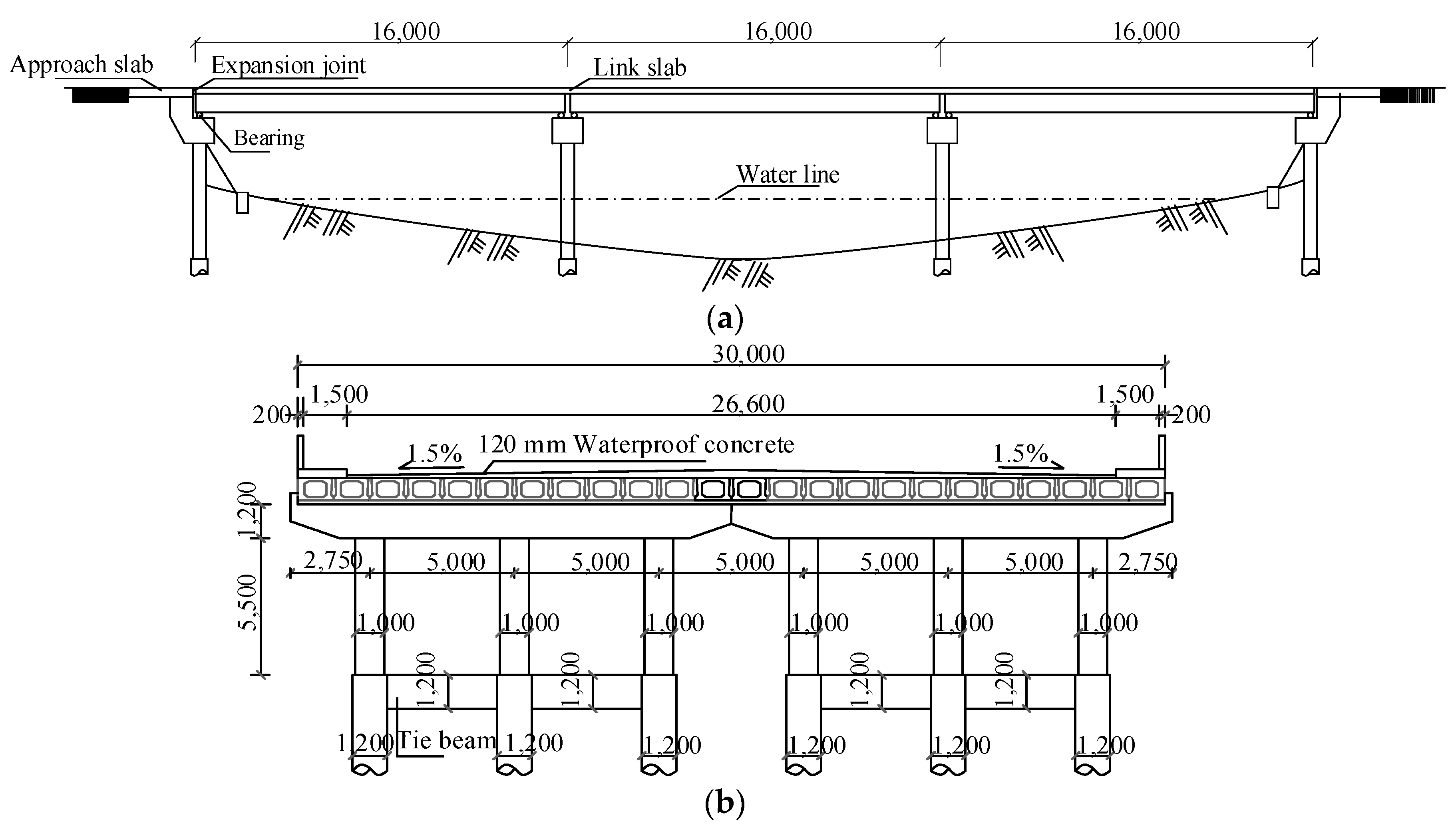
Figure 2.
Observed cracks and damage in the bridge deck. a) Cracks in the link slab. b) Damage in the expansion joint.
Figure 2.
Observed cracks and damage in the bridge deck. a) Cracks in the link slab. b) Damage in the expansion joint.
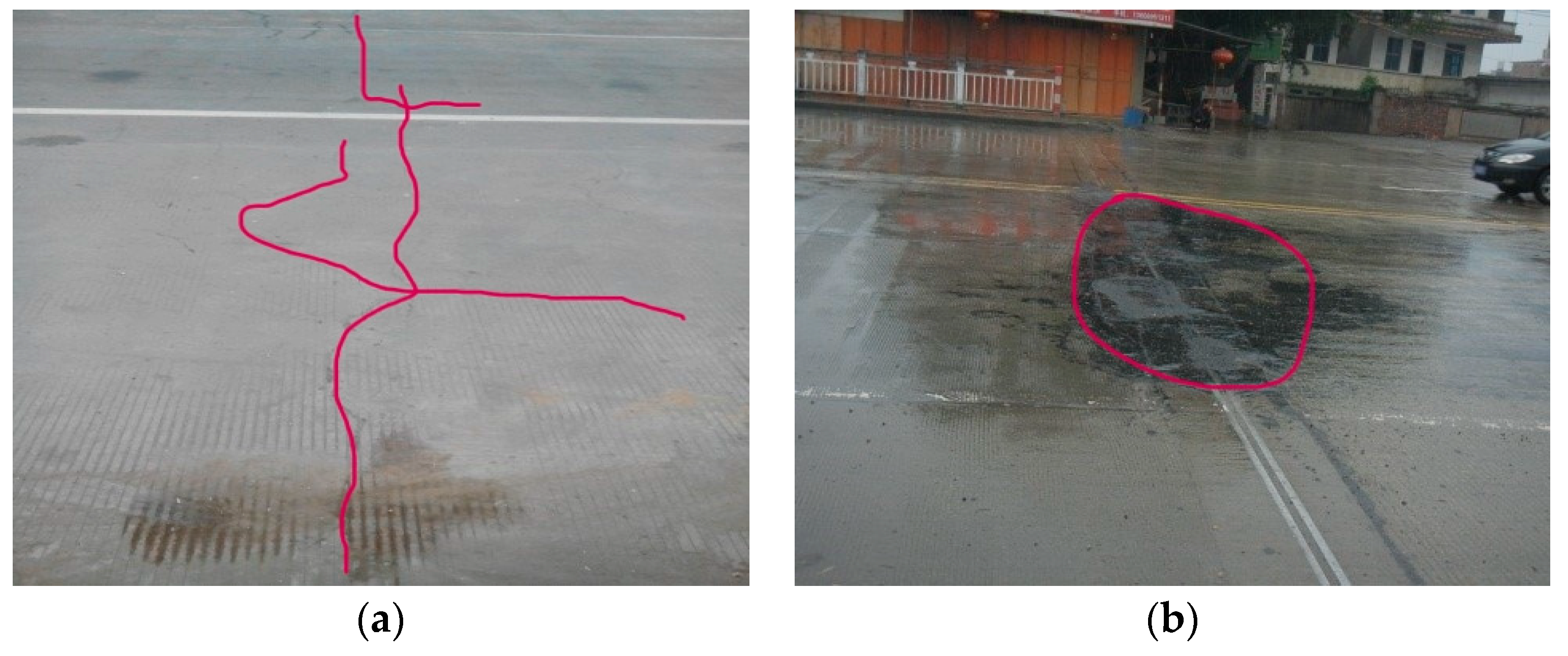
Figure 3.
Views of distress in the voided slabs and water leakage on the top of the abutment. a) Reinforcement corrosion and concrete spalling at the soffit of the voided slab. b) Water leakage on top of abutment.
Figure 3.
Views of distress in the voided slabs and water leakage on the top of the abutment. a) Reinforcement corrosion and concrete spalling at the soffit of the voided slab. b) Water leakage on top of abutment.
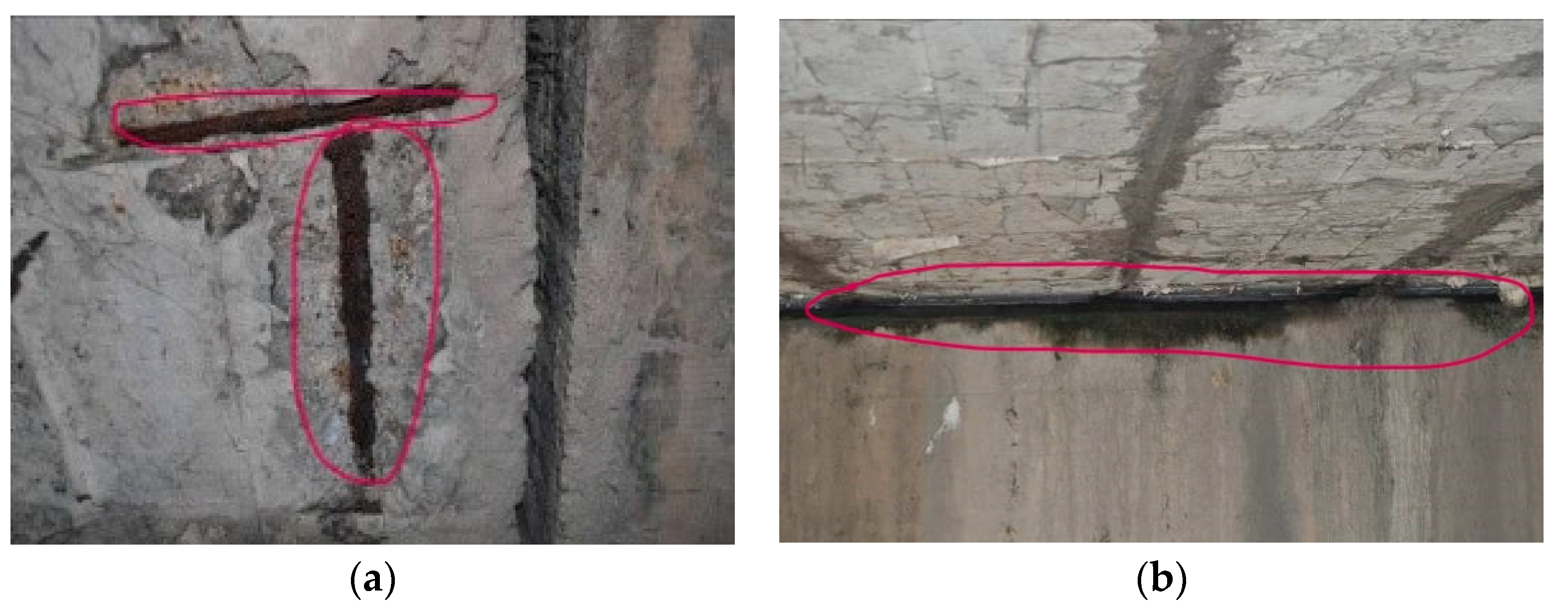
Figure 4.
Retrofitting scheme for the Jinpu Bridge (unit: mm). a) Elevation. b) Cross-section.
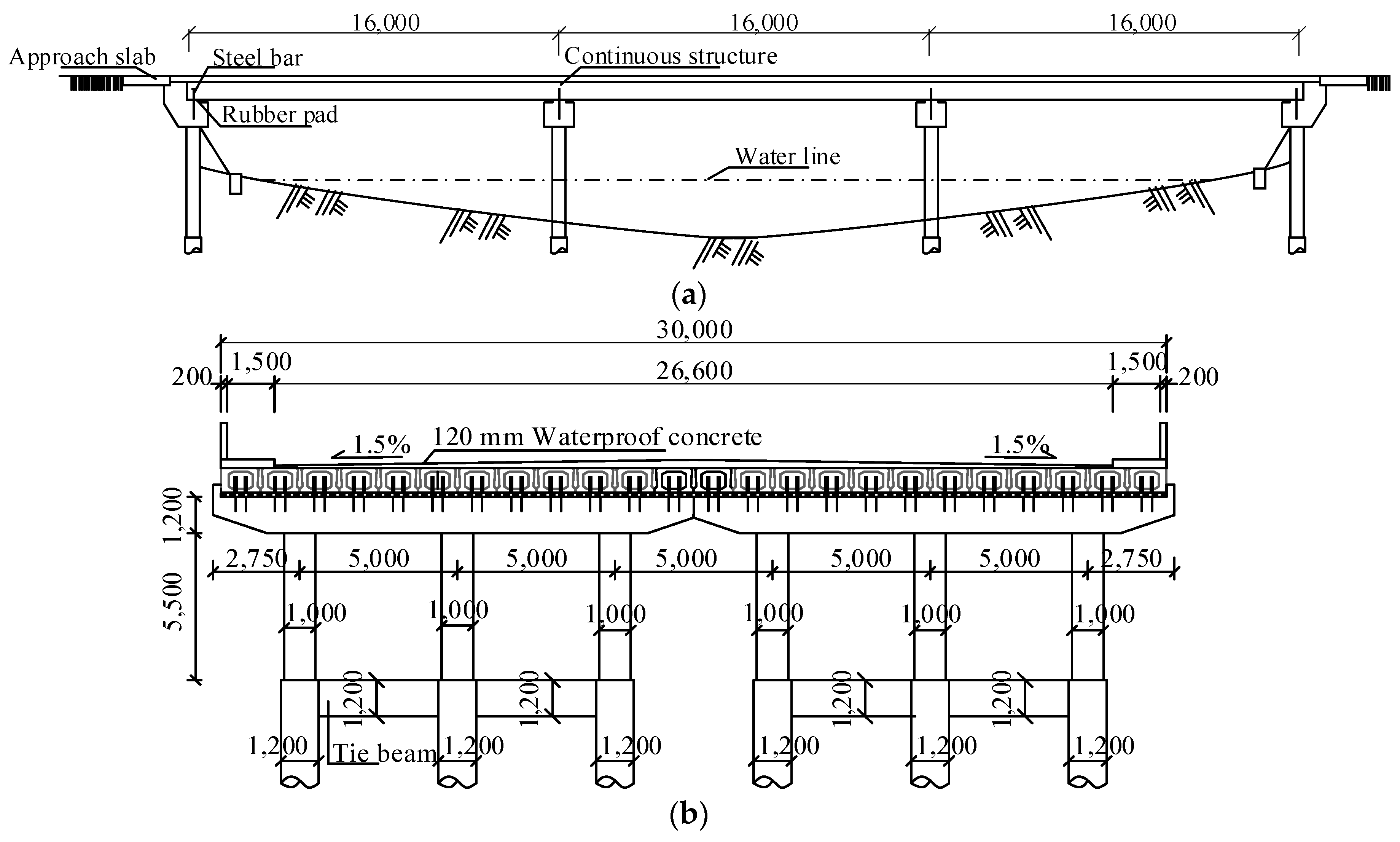
Figure 5.
Photos of the Jinpu Bridge after retrofitting. a) Side view. b) Top view of the deck.
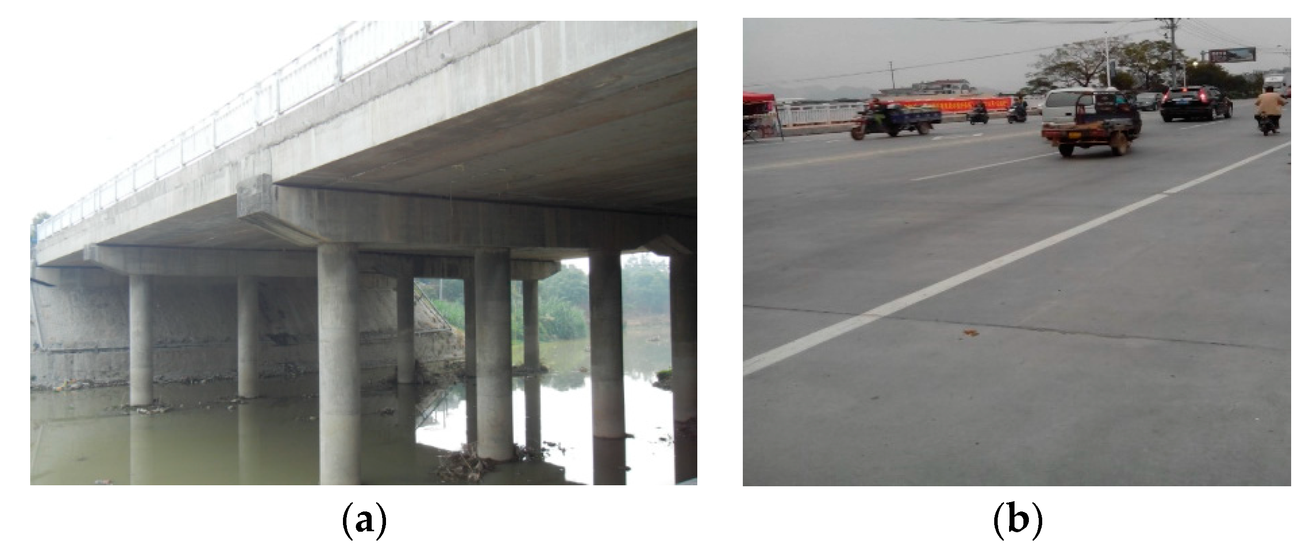
Figure 6.
Configurations of the new cast-in-situ slab portion between the new voided slabs over the pier (unit: mm). a) Elevation of the slab portion over pier. b) Cross-section I-I. c) Cross-section II-II.
Figure 6.
Configurations of the new cast-in-situ slab portion between the new voided slabs over the pier (unit: mm). a) Elevation of the slab portion over pier. b) Cross-section I-I. c) Cross-section II-II.
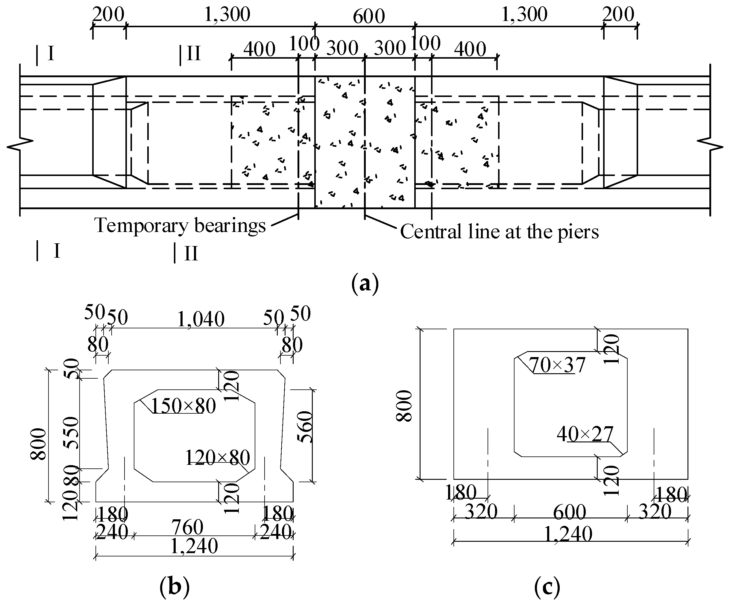
Figure 7.
Reinforcement details of the continuity segment (unit: mm).
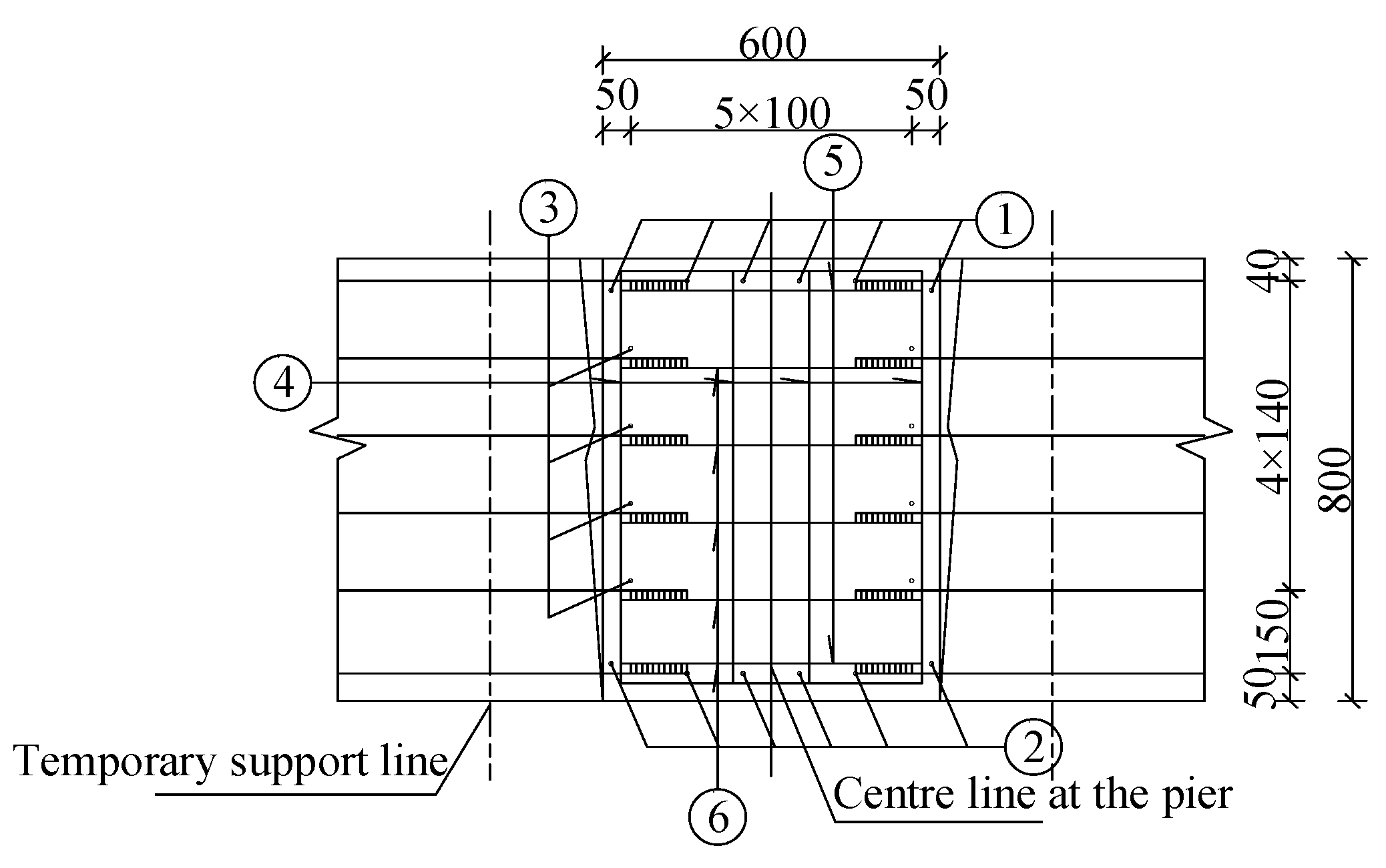
Figure 8.
Details of the semi-fixed dowel joint over pier (unit: mm). a) Details of the joint in the longitudinal direction. b) View of the joint in the transverse direction.
Figure 8.
Details of the semi-fixed dowel joint over pier (unit: mm). a) Details of the joint in the longitudinal direction. b) View of the joint in the transverse direction.
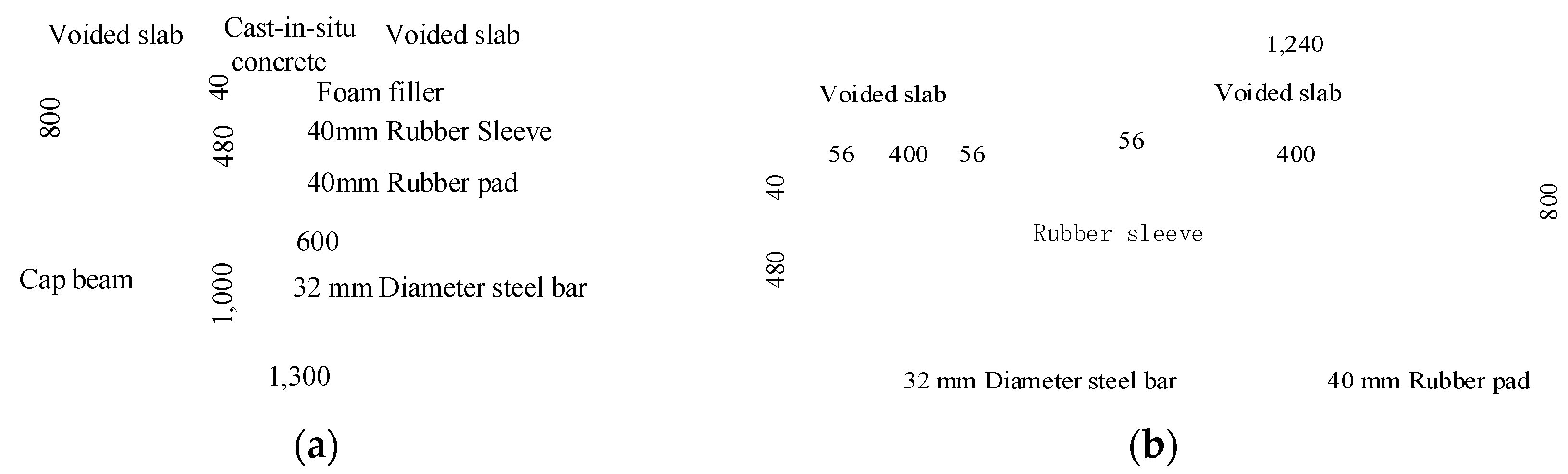
Figure 9.
Photo of the continuous segment with dowels over the pier before concrete casting.
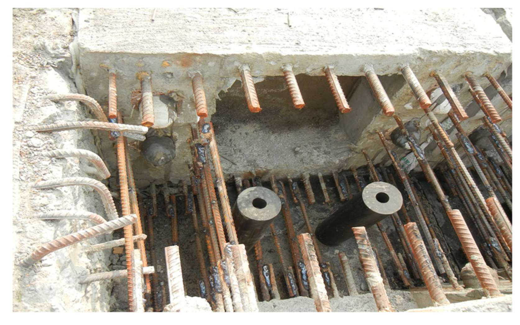
Figure 10.
Schematic diagrams of the semi-fixed dowel joint over the abutment (unit: mm). a) Joint configuration. b) Joint reinforcement.
Figure 10.
Schematic diagrams of the semi-fixed dowel joint over the abutment (unit: mm). a) Joint configuration. b) Joint reinforcement.
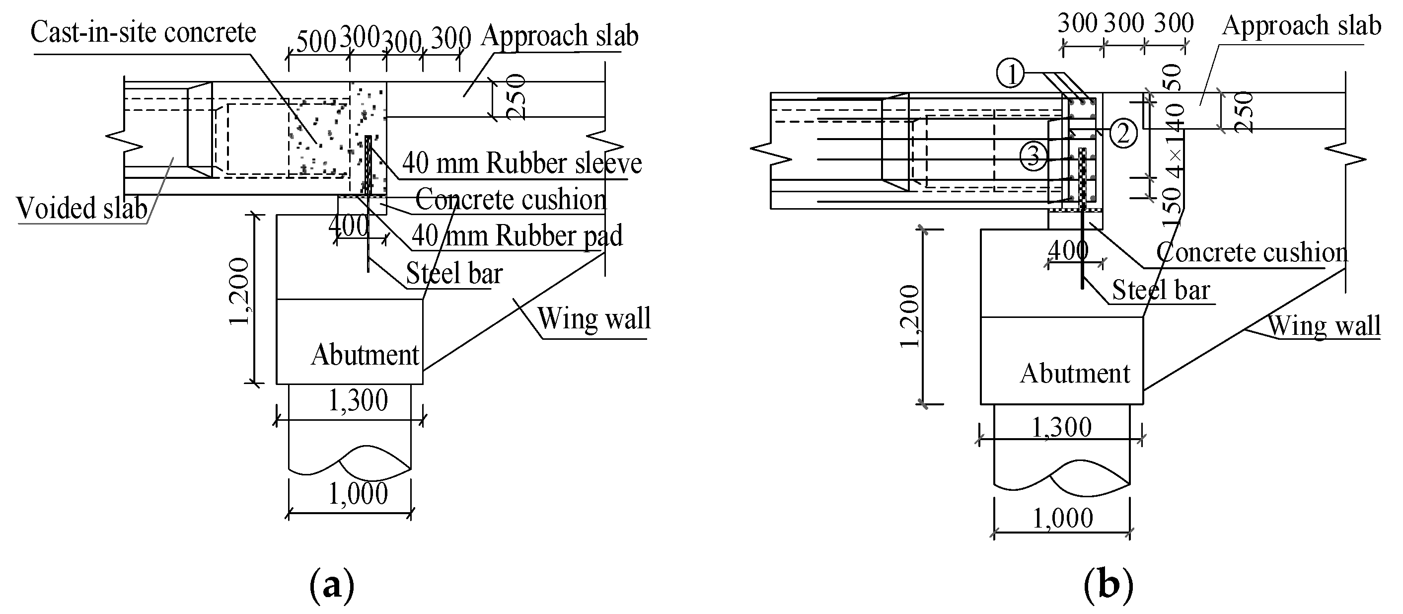
Figure 11.
Cross-section in the jointless abutment (unit: mm). a) Cross-section in the abutment and approach slabs. b) Details of the expansion joint.
Figure 11.
Cross-section in the jointless abutment (unit: mm). a) Cross-section in the abutment and approach slabs. b) Details of the expansion joint.
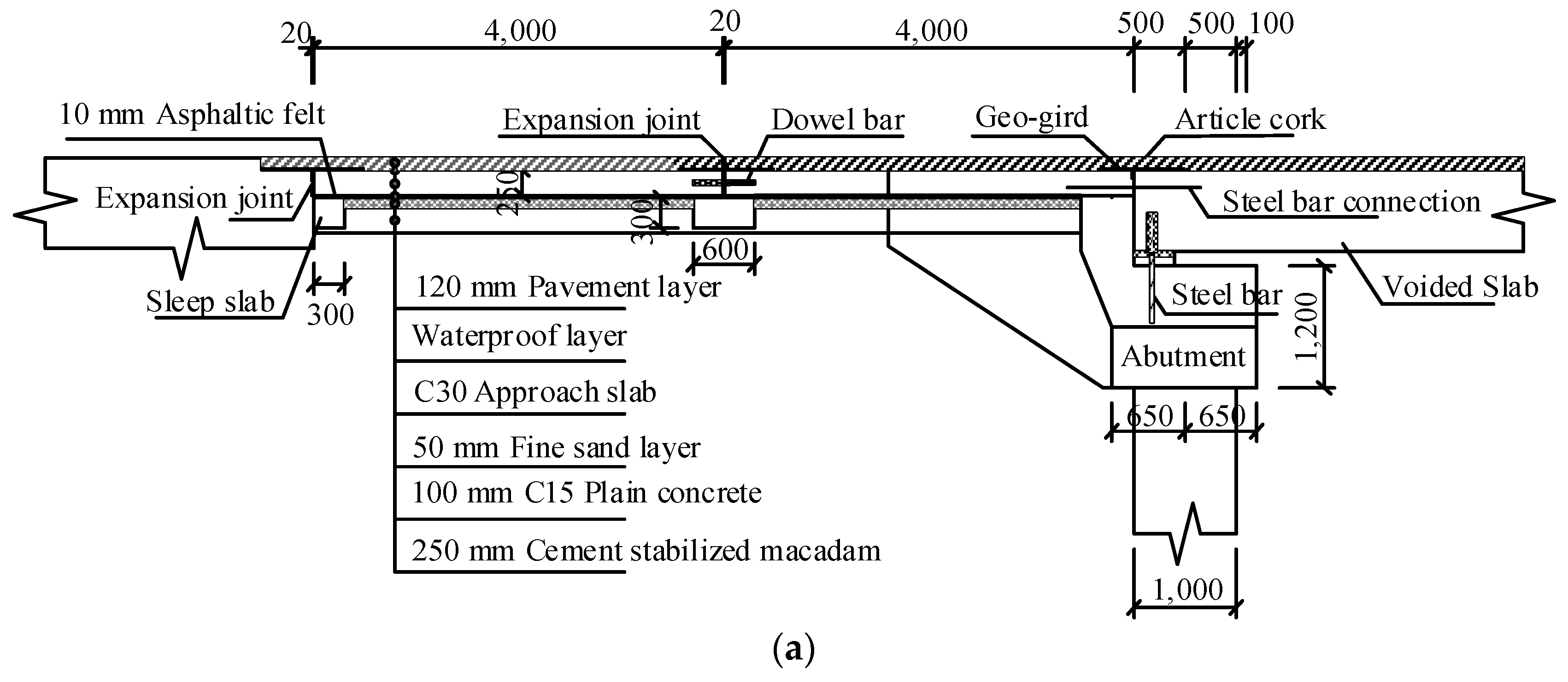
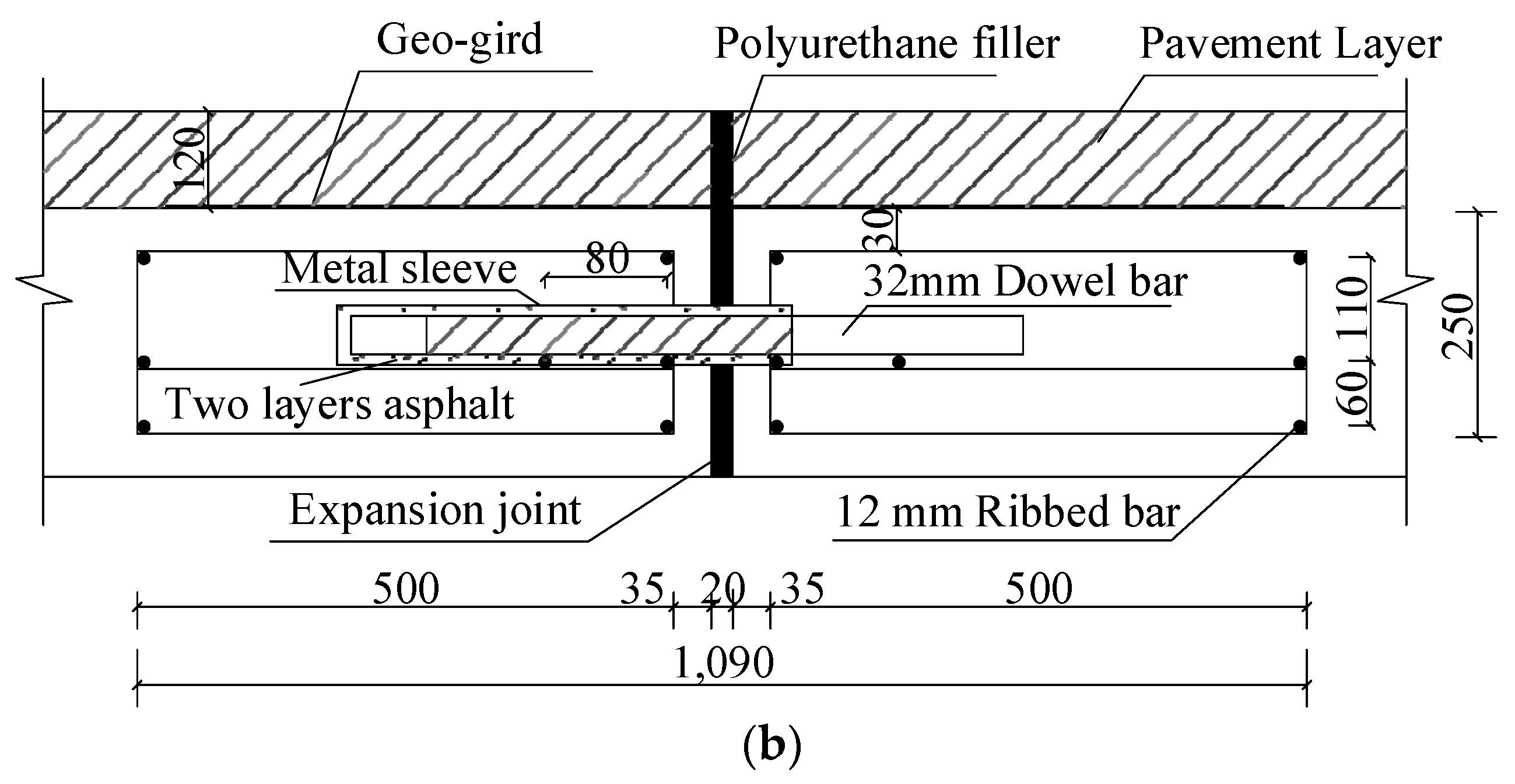
Figure 12.
Finite element model of the retrofitted bridge.
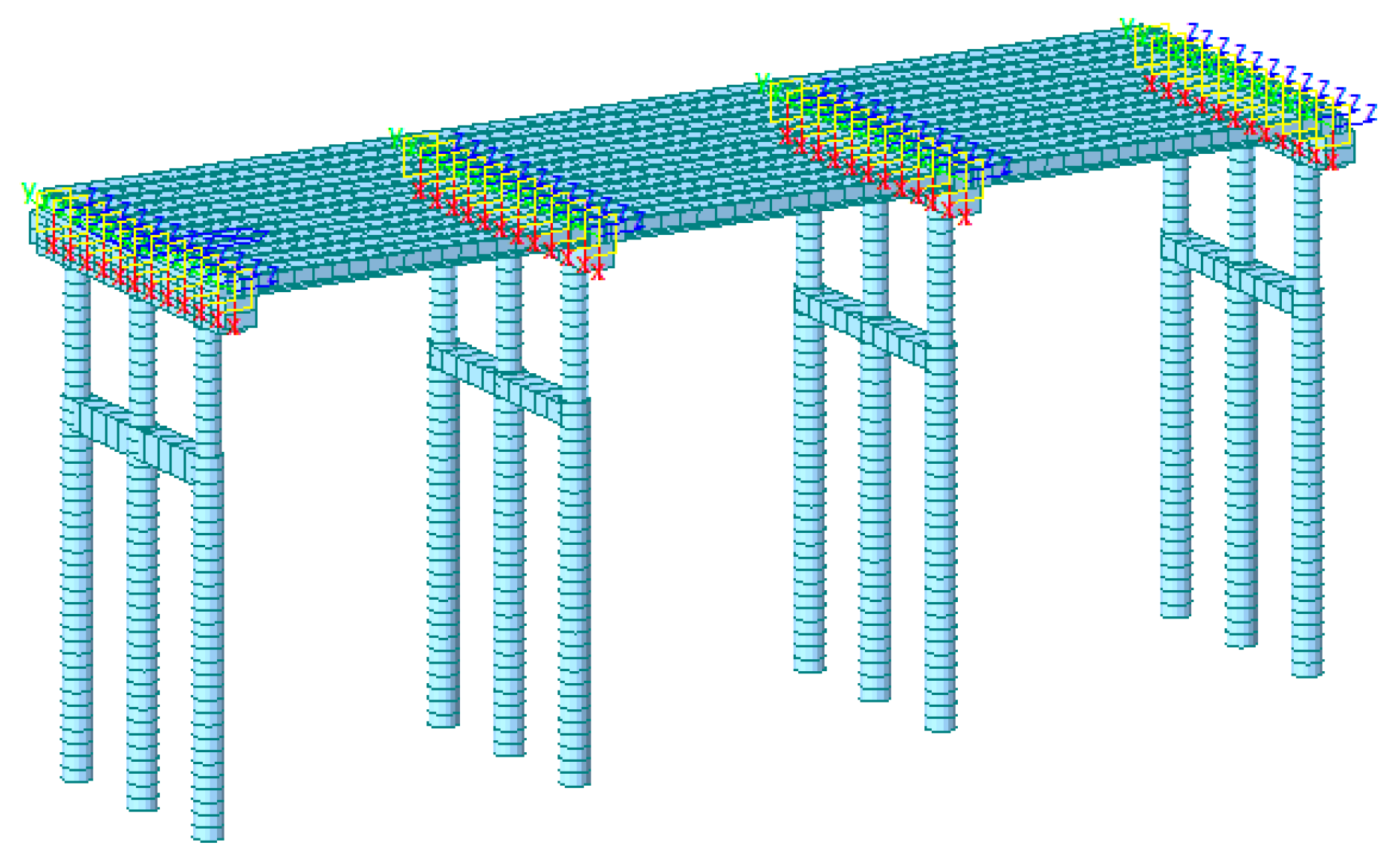
Figure 13.
Spectrum functions. a) E1. b) E2.
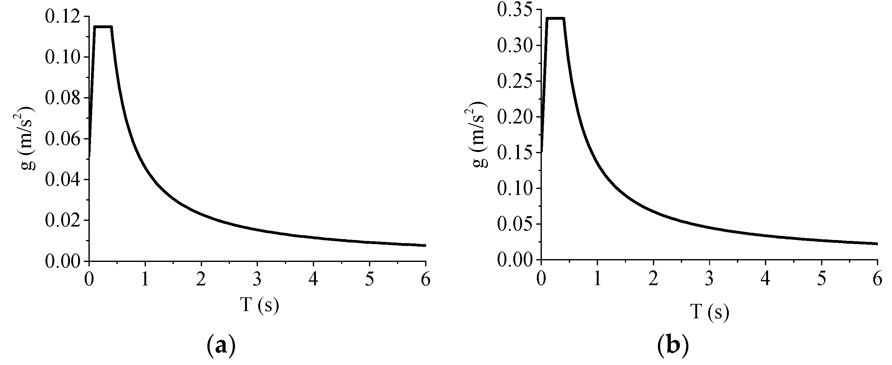

Table 1.
Comparison of beam internal forces in different bridge systems.
| Bridge-System | Abutment | Midspan | Interior Support | |
|---|---|---|---|---|
| Shear Force (kN) |
Moment (kN·m) |
Shear Force (kN) |
Moment (kN·m) |
|
| Simply-supported bridge | 505.9 | 1003.4 | 505.9 | 0 |
| Semi-integral bridge | 482.9 | 891.9 | 538.6 | -423.8 |
| Scale down (%) | 4.5 | 11.1 | -6.4 | - |
Table 2.
Maximum displacements of beam ends.
| Loading Combination | Earthquake Direction |
∆1 (mm) |
∆2 (mm) |
|
|---|---|---|---|---|
| Dead load and E1 | X | 3.9 | 28.1 | 86.1% |
| Y | 3.2 | 27.9 | 88.5% | |
| Dead load and E2 | X | 11.6 | 82.6 | 80.1% |
| Y | 9.3 | 82.1 | 88.6% |
Table 3.
Ultimate and calculated moments and shear forces of pier.
| Loading Combination | Earthquake Direction |
Mr (kN·m) |
Mp (kN·m) |
Vr (kN) |
Vp (kN) |
|---|---|---|---|---|---|
| Dead load and E1 | X | 508.9 | 2146.5 | 77.5 | 1125.9 |
| Y | 229.7 | 106.3 | |||
| Dead load and E2 | X | 984.7 | 161.8 | ||
| Y | 234.7 | 312.6 |
Table 4.
Ultimate displacement and calculated displacement of pier.
| Loading Combination | Earthquake Direction |
Δr (mm) |
Δu (mm) |
|---|---|---|---|
| Dead load and E1 | X | 2.6 | 52.4 |
| Y | 1.3 | ||
| Dead load and E2 | X | 7.7 | |
| Y | 3.9 |
Disclaimer/Publisher’s Note: The statements, opinions and data contained in all publications are solely those of the individual author(s) and contributor(s) and not of MDPI and/or the editor(s). MDPI and/or the editor(s) disclaim responsibility for any injury to people or property resulting from any ideas, methods, instructions or products referred to in the content. |
© 2024 by the authors. Licensee MDPI, Basel, Switzerland. This article is an open access article distributed under the terms and conditions of the Creative Commons Attribution (CC BY) license (http://creativecommons.org/licenses/by/4.0/).
Copyright: This open access article is published under a Creative Commons CC BY 4.0 license, which permit the free download, distribution, and reuse, provided that the author and preprint are cited in any reuse.


