
Submitted:
09 November 2024
Posted:
12 November 2024
You are already at the latest version
Abstract
As autonomous vehicle (AV) capabilities expand, it is important to assure their safety during testing and deployment for public usage. While several testing regulations have been proposed in research, US federal, and even global guidelines for low-speed vehicles in metropolitan settings, regulations for high-speed travel are mainly vacant. This is especially true for regulations relating to AV emergency obstacle avoidance maneuvers (EOAMs). With the motivation of filling this gap, research reported in this manuscript introduces a general obstacle avoidance capability assessment (GOACA) method for AVs traveling at highway speeds. This GOACA includes test modes including interactions with car and bicycle active road objects (AROs) in rural and urban highway settings. These tests are novel in their definitions, methodologies, and execution, especially in the context of AV driving at highway speeds. This research proposes a test evaluation protocol such that it could serve as a foundation for an official regulation in the future. The proposed GOACA tests include adjacent traffic vehicles which have not been utilized in the prior literature when considering EOAMs within a holistic AV system context. The use of the proposed GOACA method is illustrated using high fidelity simulations of an EOAM algorithm. Based on the assessments, vehicle-to-vehicle (V2V) communication is recommended for usage with AVs at highway speeds for critical safety. This is especially true when considering oncoming traffic and low road surface friction conditions.
Keywords:
autonomous vehicle
; active road object
; emergency obstacle avoidance maneuver
; vulnerable road user
; vehicle-to-vehicle
; V2V
1. Introduction
There have been many autonomous shuttle deployments in recent years in geo-fenced areas [1], [2]. There have also been increasing levels of public road deployment of autonomous driving. The level of autonomy in a vehicle is classified using SAE’s levels of autonomy [3]. There have been series-production vehicles with SAE-level L2+ and L3 autonomy. The most basic function of an autonomous or automated driving vehicle is to plan and track its own path [4]. Once an autonomous vehicle (AV) is able to follow a desired path, it should be able to handle obstacles along that path safely. An AV should, therefore, have a certified level of safety especially when driving at high speeds. This certified level of safety requires the AV to be able to avoid collisions with other cars and bicyclists while driving at high speeds. Such safety assessment methods for certification of AV operation especially at highway speeds have been missing which forms the motivation for the research in this paper. Consequently, this paper introduces an implementable method for general obstacle avoidance capability assessment for AVs which can be used for certification purposes before permitting public road deployment.
When considering the deployment of an AV, safety of the vehicle’s occupants, of vulnerable road users (VRUs), and of passengers in other nearby vehicles, are the highest priorities. Modern AVs have developed systems that allow them to navigate urban environments quite well, dealing with a wide variety of situations, and potential safety concerns. Likewise, Advanced Driver Assistance System (ADAS) development has upgraded human-driven vehicle safety substantially in the past 10 to 15 years. These systems are primarily used on highways as Adaptive Cruise Control (ACC), Lane-Keeping Assist (LKA), Lane Centering Assist (LCA), Lane Departure Warning (LDW), and Automated Emergency Braking (AEB), among others [5]. To provide a fuller range of capabilities, an AV should be able to effectively navigate emergency situations at higher speeds or on slippery surfaces safely, or at least recognize when those situations are unfolding and minimize injuries or fatalities for the AV’s occupants, VRUs, and occupants in other nearby vehicles. However, capabilities for AVs faced with emergency situations outside of normal driving, especially at highway speeds and/or slippery surfaces, have not been addressed in standard on-road testing and in assessment procedures used by certification bodies.
In this paper, tests are proposed that can aid validation of an AV for highway-related emergency situations. The purpose of these tests is to provide a variety of situations that require the full AV system to work in harmony to avoid striking the active road objects (ARO) or at least slow down and minimize harm to the AV’s occupants, local VRUs, and other vehicle occupants. These tests are not meant to cover every possible high-speed or slippery-surface situation that an AV might face, but rather, cover enough situations that can assure the AV will have effective and safe performance under broadly defined emergency circumstances. These validation and verification tests, their corresponding testing protocols, and scoring recommendations are provided in this paper and are denoted as General Obstacle Avoidance Capability Assessment, abbreviated as GOACA.
The various sections of this paper will review the following. Regarding the GOACA: foundational works defining AV testing terminology and nuances between the GOACA and electronic stability control (ESC) regulation test [6], the GOACA’s overall function as an assessment and why it is necessary, the specific tests included in the assessment, a sample of the GOACA using the AV and emergency obstacle avoidance maneuver (EOAM) framework borrowed from and discussed in [7], results and impressions from the test, and recommendations moving forward. This GOACA is proposed as a novel full-system AV emergency capability test that has not been previously proposed or implemented in the literature. The discussion in this manuscript provides a foundation for this recommended test which should be implemented for any AV deployed for public use in the future.
It is important to note that several efforts have already been made to address foundational test requirements for AVs. These requirements have come in the form of listing and defining key terminology (SAE – [8], NHTSA – [5], RAND – [9], NIST – [10], SAE ITC – [11] ), reference frameworks for test descriptions and metrics for measuring test outcomes ( Waymo – [12], [5] ), United States federal and state-based testing and deployment guidelines ( Texas CAV Task Force [13], [14] ), literature reviews of verification and validation activities [15], commentaries on what denotes enough testing to deploy AVs in a slow rollout [9] and what is not enough for deployment [16]. Each of these pieces are useful in the goal of understanding the capabilities of AVs and developing consistent test methodologies for which AV developers can prepare. However, most of these efforts have stopped short of defining a specific test in the form of designated rules and regulations. Some tests have been described like those in references [5] and [10], but none have tackled the emergency maneuvers for AVs. Thus, there exists an open space for suggested tests for full-system AV emergency obstacle avoidance maneuver [7] capability assessment. This paper proposes the general obstacle avoidance capability assessment (GOACA) method for AVs, to fill this high-speed assessment method need that is present in the literature.
The GOACA method presented in this paper emphasizes full AV system harmony in avoiding active road objects (AROs) which are nearby other vehicles and vulnerable road users. The full AV system includes sensing, perception, decision-making, control, and actuation. Additionally, due to the emergency nature of these GOACA maneuvers, vehicle stability is also tested as the AV’s tires are pushed to their adhesion limits during the assessment. In some ways, this can be visualized as an enhanced, full-system AV adaptation of the FMVSS 126 (ECE-13) electronic stability control (ESC) regulation test, which is designed to verify and validate the performance capability of ESC systems for all road-going vehicles, especially those which are human-driven [17]. Note that the FMVSS126 procedure was designed to test the vehicle’s dynamic ability to apply evasive steering maneuvers that mimic a double lane change (sine with dwell) that is extreme enough to engage the vehicle’s ESC system. It is not suggested that this GOACA replace the FMVSS 126 but rather be paired with it to assess an AV’s emergency maneuver capability. The caveat is that the AV should perform both the GOACA and FMVSS 126 tests autonomously. Details regarding how an AV can perform the FMVSS 126 test autonomously have been reported in [6].
Specifically, the GOACA method presented in this paper details driving scenarios that require emergency obstacle avoidance maneuver functionality to avoid striking one or more active road objects (AROs). As mentioned earlier, successful performance in the GOACA requires synchronization and accord between the various high-level functions of an AV: sensing, perception, decision-making/planning, control, and actuation. Additionally, for situations when a collision between the AV and an ARO is imminent, the AV needs to reduce its speed beyond particular threshold values, to minimize potential harm to its occupants or to nearby VRUs and other vehicle occupants. A scoring system is implemented in the GOACA to recognize the AV’s ability to mitigate collision damage when full avoidance of the ARO is not possible.
The proposed GOACA is deemed an essential addition to current AV-recommended development tests. This is because AVs deployed for public use should have the capability to drive as safely or safer than human drivers [16]. While it is apparent that modern AVs deployed for urban use are quite capable and safe in ordinary, non-extreme driving situations [18], rigorous (public) acknowledgment of matching or exceeding human driving capabilities in emergency obstacle avoidance maneuver situations has not occurred. Since the protection of an AV’s occupants, local VRUs, and other nearby vehicles’ occupants are the highest priorities in mobility, even dynamic emergency obstacle avoidance maneuvers should have standards of performance for any AV allowed to travel at highway speeds (55 km/h or greater) [19]. It is, thus, the intention of this paper to provide the initial testing definition and methodology for a GOACA targeted at AVs conducting emergency obstacle avoidance maneuvers.
It is noted that this proposed GOACA should serve as a baseline, welcoming additions, improvements, and general evolution with time and inputs/feedback from those conducting and preparing for the tests, as well as those generally vested in the promise of AVs as safe mobility solutions. The following sections will explain the recommended GOACA tests, test methodologies, scoring, and a sample of simulated results from emergency obstacle avoidance maneuvers.
2. Main GOACA Test Definitions and Methodology
2.1. General GOACA Methodology
The GOACA method proposed in this paper consists of four main test modes that the AV encounters:
- ARO ahead slowing to a stop on a two-lane highway, with and without oncoming traffic,
- ARO cutting in front of the AV on a three-lane highway with various additional traffic vehicles,
- ARO cutting out of the lane of AV on a three-lane highway, revealing a stopped vehicle ahead, with various additional traffic vehicles,
- ARO encroaching into the lane of the AV perpendicular to the AV direction of travel, on a two-lane divided rural highway with intersection (4a) involves a car ARO, and 4b) involves a bicyclist target).
For 1) – 3) the ARO is another car and for 4) a car is used for one set of tests 4a), and a bicycle is also used for a set of tests 4b). The sample test matrices for 1) (Table 1) and 2) through 4) (Table 2) can be seen below.
The details of each of these GOACA tests are provided in the following subsections.
2.1.1. High Surface Mu GOACA Testing
Each GOACA test is meant to be performed on a homogeneous dry surface in a closed track or proving ground setting, with road surface friction . The test course for 1) and 4) consists of a two-lane highway with painted lines, uniform lane widths of 2 m, and static cars parked on the right side of the right-most lane approximately 1.5 m from the right-most painted line (Figure 1).
There are 12 parked cars of various types, shapes, and sizes in the two-lane highway setup with 30 m of longitudinal spacing between them. The ARO car or bicycle that encroaches into the AV’s lane of travel perpendicularly is located halfway between the sixth and seventh parked cars.
For tests 2) and 3) a three-lane highway is used and includes uniform lane widths of 2 m (Figure 2). Parked cars can be added but are not necessary for these tests.
2.1.2. Lower Road Surface Mu GOACA Testing
For the simulated GOACA tests in this paper, the road surface friction value used is μ=1.0 and corresponds to dry road conditions. It is noted that other road surface friction levels on asphalt with rain (μ≅0.7), snow (μ≅0.3), and ice (μ≅0.1) should be used for these tests but are recommended to be tested in a virtual environment. This is because the GOACA tests require significant proving ground test space – suggested to be at least a 200 m by 400 m rectangle – and this space can be difficult to achieve with wet, snowy, and icy surfaces, especially with repeatable homogeneity. Various warm weather-proving grounds have asphalt that can be wet with sprinkler systems, along with wet Jennite surfaces, basalt tiles, and ceramic tiles [20], all of which can be used to simulate lower surface friction in a proving ground setting. However, these are usually not in a large enough space to satisfy the requirements of the GOACA. Additionally, cold weather proving grounds exist [21] with large snowy and icy surfaces, but the surfaces cannot guarantee repeatable homogenous properties throughout several tests. Thus, it is recommended that the GOACA tests on these surfaces are conducted virtually, with either software-in-the-loop (SIL) or hardware-in-the-loop (HIL) methods, like those stipulated in the ECE-13 regulation test for ESC (similar to FMVSS 126, created by United Nations Economic Commission for Europe, or ECE) [22].
2.1.3. Active Road Objects (AROs)
The active road objects (AROs) consist of vehicle objects in CarSim for tests 1) through 4a), as well as a bicyclist VRU target for test 4b) with dimensions, colors, and reflectivity as specified by the European Automotive Manufacturer’s Association [23]. This same bicyclist VRU target is used in the AEB VRU Euro NCAP tests, among others [24]. This bicyclist target is represented as a detectable object and animator asset in CarSim (CarSim 2021.0). The preferred ARO vehicle object is the official global vehicle target (GVT) used in Euro NCAP AEB VRU, and ACC highway assist tests [19]. The GVT was not used in the GOACA tests featured in this paper because it was not included as an object with the version of CarSim that was used in these experiments (CarSim 2021.0); however, it is noted that GVT is included in future versions of CarSim (CarSim 2021.1) and later [25]). The unique features regarding the GVT that make it quite useful for ADAS and AV safety system tests are that it has infrared reflectivity that matches road vehicles, will break into discrete parts upon impact that are made to be reassembled several times (i.e., it is reusable with vehicle collisions) [26].
The GVT motion is provided by a motorized, low-profile, platform (Low Profile Robotic Vehicle or LPRV), on which the GVT sits, that can sustain the weight of common road vehicles. The GVT can be contacted by a road vehicle during a test, and the platform can be run over by the vehicle under test [27]. The GVT with LPRV should be used as the ARO in motion, traffic objects, and parked vehicles in the physical manifestation of GOACA because they are of uniform, standardized size, and they can easily be reassembled (within 15 minutes) if the AV collides with the GVT, and they have known reflectivity detectable by common radar, lidar, and infrared sensors used in modern road vehicles. It is also recommended that the GVT is utilized in simulation platforms, when available.
For the simulation experiments in this paper, the ARO for tests 1) through 3) was a D-Class minivan with detectable length, width, and height of 3000, 2020, and 1554 mm respectively (Figure 3), where the ARO car used in 4a) was a Full-Size SUV with a detectable length, width, and height of 3140, 2384, and 1677 mm respectively (Figure 4).
2.1.4. Autonomous Vehicles (AV)
The autonomous vehicle (AV) used in the GOACA simulation experiments within this paper is the E-Class sedan, rear-wheel-drive, without ABS or ESC. One feature that was added for the AV was the addition of a left-facing and right-facing sensor that can be thought of as a camera sensor with computer vision capabilities. The computer vision capabilities are shown in the sensor's ability to detect multiple object types including cars, bicycles, and pedestrians. These sensors were added so that the AV can detect secondary AROs in adjacent lanes in the form of traffic vehicles. The original front-facing sensor in addition to the left and right-facing sensors can be visualized in location and field-of-view on the AV in the CarSim Visualizer (animation) (Figure 5)
Many modern vehicles, and especially AVs, have these types of side-detection sensors in addition to even more sensors on the sides and rear of the vehicle body. An AV logic update was the utilization of the side-facing sensor inputs data to recognize if AROs were in adjacent lanes and traveling in the same direction of travel as the AV. If this is true, the AV will not attempt an emergency obstacle avoidance lane change into that adjacent lane.
2.2. Cut-in Tests
The Cut-In GOACA tests (Table 2) consist of the AV traveling in the center lane of a three-lane highway with the ARO traveling in the adjacent lane to the right of the AV. The ARO then cuts into the middle lane where the AV is driving while traveling at half the speed of the AV. The AV must perform an emergency obstacle avoidance maneuver to avoid hitting the ARO. The trajectory that the ARO uses to enter the middle lane is based on a fifth-order polynomial geometric path, with constant speed. A top-view illustration of the Cut-In test scenario can be seen in Figure 6.
The parameters of the polynomial path used depend on the scenario (initial speed of the AV) and can be seen in the table below (Table 3). It should be noted that the same ARO trajectories were used for the Cut-In and Cut-Out-and-Reveal scenarios, based on initial AV speed, but only the time-to-collision (TTC) between the ARO and AV changed.
The target TTC between the AV and ARO upon the ARO’s encroachment into the lane of the AV helps determine where the ARO should start the scenario relative to the AV and at what time the ARO should begin its Cut-In maneuver. An example of the geometric path used for the Cut-In ARO can be seen in Figure 7 which was used for the 120 km/h AV initial speed scenario.
The timing of ARO’s encroachment into the lane of the AV was such that the time-to-collision (TTC) upon entering the lane of the AV was between 2 to 3 s for the 165, 120, and 90 km/h scenario, and 3 to 4 s for the 55 km/h scenario (Table 3). Also, the target lateral acceleration for the ARO during its Cut-In maneuver, regardless of the speed of travel, was 1.5 m/s2. It is noted that the same ARO trajectories for the Cut-In tests are used for the Cut-Out tests, with the difference being that for the Cut-Out-and-Reveal tests, the ARO begins in the same (middle) lane as the AV.
The visualization of the ARO beginning to cut into the middle lane where the AV is driving during the 120 km/h scenario can be seen in Figure 8.
2.3. Cut-Out-and-Reveal Test
The Cut-Out-and-Reveal test was also performed on the three-lane highway like the Cut-In test. It featured the ARO starting each test in the same middle lane as the AV, also traveling at the same longitudinal speed as the AV. At a specified time in the scenario, the ARO cuts out of the middle lane to reveal a stopped vehicle ahead. The timing for which the ARO would cut out of the AV’s lane to reveal the stopped vehicle should be such that for the 165, 120, 90, and 55 km/h scenarios, the initial TTC between the AV and the stopped vehicle should be between 1 – 2 s, 1 – 2 s, 1 – 2 s, and 2 – 3 s (Table 4).
Upon perception of the stopped vehicle, the AV must then perform an emergency obstacle avoidance maneuver to avoid hitting the stopped vehicle. The trajectories used for the ARO cutting out of the AV’s lane are the same as those used in the Cut-In tests, with the difference being the TTC between the AV and stopped vehicle upon initial perception (Table 4).
A top-view illustration of the Cut-Out-and-Reveal test scenario can be seen in Figure 9.
An example of the initial perception of the stopped vehicle by the AV in the 90 km/h scenario can be seen in Figure 10.
2.4. Additional Traffic
Traffic vehicles were added to each of the tests 2) through 4) to simulate a larger variety of highway driving traffic situations. One traffic scenario includes one traffic vehicle in the left adjacent lane (Figure 11), and another traffic scenario includes two traffic vehicles in the left adjacent lane (Figure 12); these additional traffic scenarios are included for each test speed (Table 2).
The additional traffic vehicles prevent the AV from safely (without collision) performing a lane change into the leftmost lane. This suggests that the AV must perceive the left lane is occupied. So, instead of performing a lane-change maneuver, the AV must perform limit braking to mitigate the severity of the potential collision with the vehicle (either Cut-In ARO or stopped vehicle from the Cut-Out scenario) ahead.
2.5. Perpendicular Encroachment on Divided Rural Highway with Intersection Test
Scenarios meant to emulate AV travel on a divided four-lane rural highway with two lanes of forward traffic per side were also included in the GOACA test matrix (Table 2). These divided rural highways can include a median and intersections which allow for traffic to travel perpendicular to the main four lanes, to either enter the highway main flow or get from one side of the highway to the other. A top-down view of this type of rural highway including an intersection, along with entrance and exit lanes, and noted directions of travel can be seen in Figure 13 [28].
A 3D rendering of a similar type of divided rural highway with an intersection can be seen in Figure 14 [29].
These types of divided rural highways with intersections can prompt potentially dangerous traffic scenarios for human-driven vehicles as well as AVs, especially if a vehicle is attempting to cross the highway, perpendicular to the direction of travel of the four main lanes. It was therefore important to include a representation of this situation in the GOACA tests. While an intersection was not utilized in the virtual proving ground setup of this scenario, a potentially more difficult setup with parked cars lined up along the right side of the road was implemented, with the ARO emerging from the line of parked cars (Figure 1), perpendicular to the direction of travel of the AV, as illustrated in Figure 15.
The Perpendicular Encroachment on the Divided Rural Highway with Intersection GOACA scenarios consisted of versions where a car (full-size SUV) would encroach into the AV’s lane-of-travel (Figure 15), and scenarios where a bicyclist target would encroach as illustrated in Figure 16.
The scenario with the bicyclist target is sadly representative of a real situation where the pedestrian with bicycle (VRU) crossed a rural Arizona highway and was fatally struck by an Uber semi-autonomous Volvo XC 90 [30]. An aerial view and visual representation of the fatal collision, along with the vehicle which struck the VRU can be seen in Figure 17.
It was noted that the sensors and perception logic within the semi-autonomous vehicle recognized the VRU crossing the street, up to 6 seconds before the collision occurred, but the automatic emergency braking (AEB) system was not turned on at the time and the operator of the vehicle did not apply braking in the vehicle until it was too late to avoid the collision [30]. This situation should be avoided with the implementation of AVs on public roads, and, thus, this type of scenario was deemed important to include in the GOACA tests.
CarSim visualizations of the Perpendicular Encroachment on the Divided Rural Highway with Intersection GOACA scenarios with the car ARO, and bicyclist ARO, can be seen in Figure 18 and Figure 19, respectively.
The starting distance of the ARO from the AV, ARO speed of travel, and AV trigger distance to stop and start ARO perpendicular encroachment into the roadway can be seen in (Table 5).
2.6. Successful Result Definition
The ideal result for each GOACA test is noted as follows:
- The AV sensing and perceiving the ARO successfully, and
- The AV performing an emergency obstacle avoidance maneuver to avoid contacting the ARO, and
- The AV ending the emergency obstacle avoidance maneuver in the original lane that it started without colliding with the ARO.
When these steps are completed in this order, the AV has successfully completed the test. However, other potential outcomes can denote partially successful test runs. Therefore, a scoring system was developed to denote the various potential outcomes between the AV, ARO, and potential traffic or parked cars in each scenario.
2.6. GOACA Scoring
A set of scoring guidelines was created and implemented for each test in the GOACA test matrices shown in Table 1 and Table 2. For a successfully completed run, the AV would achieve a full point for its score. If contact with an ARO, moving traffic vehicle, or parked car was made, partial points would be awarded if the AV’s speed at the time of contact was reduced by 20% or more, compared to the initial starting scenario speed. The point breakdown for each GOACA test can be seen in Table 6.
In the reported results, each score is reported with a corresponding color for better understanding, where 1.0 is green, 0.75 is yellow, 0.5 is orange, and 0.25 and 0.0 are both red.
3. Results and Discussion
In the implementation of the tests, we used the E-Class sedan AV in CarSim with the emergency obstacle avoidance maneuver method in our earlier work [7] with logic updates presented earlier in the paper as it performed well in the assessments. Though additional AV emergency obstacle avoidance maneuver logic updates could potentially result in better scores, the primary point of this paper is to introduce the GOACA test definitions and methodology and demonstrate its effectiveness using simulated examples. The various GOACA tests noted in the test matrices in Table 1 and Table 2 were completed, and the scores were compiled in Table 7 and Table 8, below.
3.1. Slow-to-Stop Tests
As noted earlier, the official GOACA test results are designed for a proving ground setting with a dry asphalt surface. It was discussed earlier that the GOACA test could also be conducted and verified in a simulated environment for the non-dry surfaces, to aid in reducing testing costs while increasing feasibility and safety. The Slow-to-Stop results for the simulated dry surface with can be seen in Table 7.
These results show that out of a possible 16 points, the E-Class sedan AV with the emergency obstacle avoidance maneuver of reference [7] scored 14 points. Half-point deductions occurred in the 500 m and 400 m oncoming vehicle test segments where the AV exhibited lateral contact with the oncoming vehicle after the initial lane-change maneuver. With 300 m oncoming tests, the AV was able to perceive the oncoming vehicle, remain in the original lane, and apply limit braking to decrease the magnitude of the impact with the ARO. For the other oncoming tests, the AV was either able to 1) perform an emergency obstacle avoidance lane change maneuver before the oncoming vehicle arrived, or 2) perceive the oncoming vehicle and wait until it passed, to then perform the emergency obstacle avoidance maneuver successfully. One third of successful runs with oncoming traffic occurred when the distance between the oncoming vehicle and the AV was short enough that the oncoming vehicle passed the AV before it needed to perform the emergency obstacle avoidance maneuver. In that case, after the oncoming vehicle passed, the test was largely the same as that without an oncoming vehicle.
The full Slow-to-Stop test results can be seen in Table 8. The primary takeaway from the full Slow-to-Stop test data on all surfaces is that Vehicle-to-Vehicle (V2V) communication alerting the AV of oncoming traffic before it can sense and perceive it is exceptionally important. The various test results with a value of 0.25 denoting a collision with an oncoming vehicle would amount to severe damage to the AV and likely serious injuries to the occupant if not fatalities; even though the 0.25 score shows that the AV slowed beyond the noted threshold values. The threshold values were adjusted for the lower surface friction levels, as shown in Table 9.
Thus, any oncoming collision in the GOACA test should be avoided with either better sensing and perception capabilities or added V2V capabilities for the AV notifying it of oncoming traffic and not allowing it to perform the emergency obstacle avoidance lane-change maneuver when any oncoming traffic is detected. If V2V capabilities were added for the E-class AV featured in the GOACA experiments of this paper and if it were capable of flawlessly alerting the AV of oncoming traffic before it passed the emergency obstacle avoidance maneuver point-of-no-return, then all the oncoming vehicle GOACA tests would result in a score of 0.75. Some tests might result in a score of 1.0 if the AV was able to completely stop before hitting the ARO ahead. This conservative approach would avoid taking the chance of performing a lane-change emergency obstacle avoidance maneuver even if the AV might be able to conduct it successfully without hitting the oncoming vehicle. This ethical feature within the AV emergency obstacle avoidance maneuver logic would ultimately be worth it to eliminate the deliberate possibility of putting the AV occupant into an oncoming collision situation.
3.2. Cut-In and Cut-Out-and-Reveal Tests
The summarized outputs from the Cut-In and Cut-Out-and-Reveal tests can be seen in Table 10.
Overall, the AV with emergency obstacle avoidance maneuver performed well in Cut-In and Cut-Out-and-Reveal tests with scores of 11.75 out of 12 and 10.25 out of 12, respectively. While it was expected that the emergency obstacle avoidance maneuver logic would yield successful outputs for the tests without traffic, the tests with either one or two adjacent vehicles were expected to yield frontal collisions with reduced speed, resulting in individual scores of 0.75 per test. Most of the Cut-In tests with one or two adjacent traffic vehicles and one of the Cut-Out-and-Reveal tests (55 km/h with two adjacent traffic vehicles) yielded successful run results.
One AV behavior mode that yielded a successful run with traffic came when the AV was slowing down upon the Cut-In or Cut-Out-and-Reveal events, enough that the traffic vehicles passed the AV and the adjacent lane was open for the AV to perform a lane-change maneuver. This can be seen with the 90 km/h Cut-In test with two adjacent traffic vehicles with the initial braking during the ARO Cut-In and adjacent traffic detection (Figure 20). A lane change maneuver is conducted after the AV perceives the adjacent lane is vacant (Figure 21), and successfully returns to the original lane behind the original ARO (Figure 22). The AV is behind the ARO by the time it returns to the original lane because of the significant speed reduction the AV performs while waiting for the adjacent traffic to pass before conducting the emergency obstacle avoidance maneuver.
It is also noted that including emergency obstacle avoidance maneuver lane-change lookup table data for lower speeds was important for the AV to avoid the ARO after slowing down. Thus, even though the emergency obstacle avoidance maneuver is meant for higher (highway) speeds and slippery conditions, in the situation when the AV slows down to lower speeds but still needs to perform an evasive maneuver, it was useful to have a lookup table data at the lower speeds.
3.3. Perpendicular Encroachment Car and Bicycle Tests
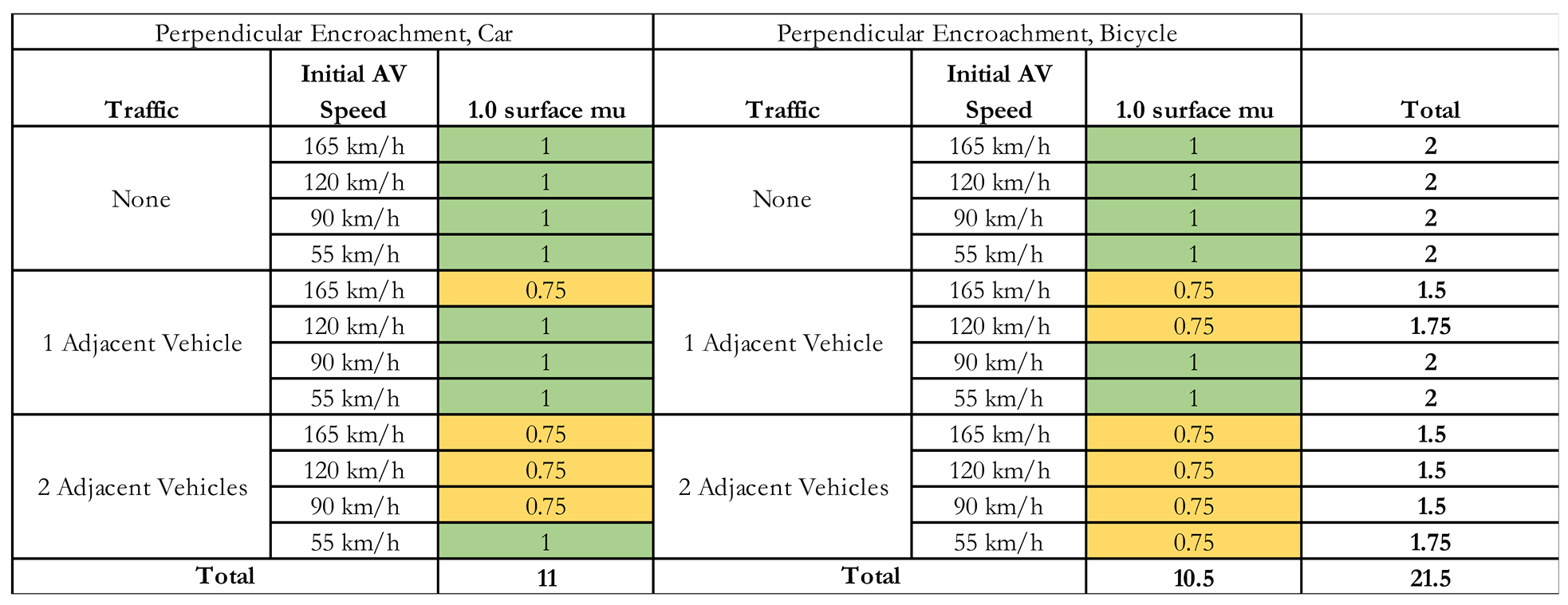
The summarized outputs of the perpendicular encroachment car and bicycle tests from the Cut-In and Cut-Out-and-Reveal cases are displayed in Table 11.
The AV with emergency obstacle avoidance maneuver logic also performed well in the Perpendicular Encroachment tests with both a car and bicycle ARO. There were no lateral collisions or collisions with speed reduction percentages less than 15. Additionally, there were tests with both the car ARO and the bicycle ARO and additional traffic where the AV either performed a successful lane-change maneuver or came to a complete stop without contacting the ARO. When a successful lane-change maneuver was performed by the AV during perpendicular encroachment by the ARO with traffic in the adjacent lane, the behavior mode was like that shown with the Cut-In and Cut-Out-and-Reveal successful lane-change modes. One example of this mode with the bicycle target ARO and one adjacent traffic vehicle can be seen in (Figure 23).
An example of EOAM behavior mode when the AV came to a complete stop to avoid the ARO, with adjacent traffic, can be seen in the 55 km/h Perpendicular Encroachment test with car ARO and two adjacent traffic vehicles in Figure 24.
The other Perpendicular Encroachment test results were mostly as expected, with the AV avoiding the perpendicularly encroaching ARO car or bicycle target for tests without traffic, and colliding with the ARO in tests with traffic, only after reducing its speed by at least 15%.
5. Conclusions
The general obstacle avoidance capability assessment (GOACA) introduced in this paper provides a foundation of emergency obstacle avoidance maneuver performance tests for AVs that can be conducted in a proving ground setting. These GOACA tests are comprehensive and challenging for the AV emergency obstacle avoidance maneuver logic, especially those that include traffic vehicles in lanes adjacent to the AV during the test. The GOACA tests definitions and methodology with scoring guidelines are novel additions to the verification and validation (V&V) landscape for AVs intending to travel at highway speeds or in slippery conditions, though it is suggested that slippery condition testing be conducted through simulation only. These tests extend beyond most emergency obstacle avoidance maneuver validation procedures that either do not include additional traffic vehicles or do not require real-time computations to perform an EOAM at highway speeds. The GOACA testing methodology presented in this paper also rewards seamless full-system AV functionality — including sensing, perception, decision-making, control, and actuation — by requiring smooth hand-offs between the AV high-level system used during normal driving, and specific dynamic driving tasks (DDTs) like an emergency obstacle avoidance maneuver.
The results in this paper showed example outputs and scoring for the GOACA tests based on the AV emergency obstacle avoidance maneuver logic of reference [7]. Moving forward, the GOACA test methodology for AVs performing emergency obstacle avoidance maneuvers should be considered for any AV intended for public use on roadways allowing highway speeds, to complement existing AV validation tests meant for lower, urban speeds (less than 55 km/h).
Concerning the results of this particular simulation experiment, at higher vehicle speeds and lower surface mu, V2V communication would be exceptionally important to alert the AV of oncoming traffic before it can sense and perceive it. While vehicle dynamic behavior varies between vehicle makes, models, loading conditions, and environmental conditions, these simulation results show that for AVs traveling at high speeds, including functioning V2V communication could equate to a matter of life and death.
Author Contributions
Conceptualization, E.L., L.G.; methodology, E.L.; software, E.L.; validation, E.L.; formal analysis, E.L.; investigation, E.L.; resources, E.L., L.G.; data curation, E.L.; writing—original draft preparation, E.L.; writing—review and editing, L.G.; visualization, E.L.; supervision, L.G.; project administration, E.L., L.G.; funding acquisition, E.L., L.G. All authors have read and agreed to the published version of the manuscript.
Funding
This research received no external funding.
Acknowledgments
The authors thank the Automated Driving Lab at the Ohio State University.
Conflicts of Interest
The authors declare no conflict of interest.
References
- Gelbal, S.Y.; Guvenc, B.A.; Guvenc, L. ; SmartShuttle: a unified, scalable and replicable approach to connected and automated driving in a smart city, in Proceedings of the 2nd International Workshop on Science of Smart City Operations and Platforms Engineering, New York, 2017.
- Wen, B.; Gelbal, S.Y.; Guvenc, B.A.; Guvenc, L. , Localization and Perception for Control and Decision Making of a Low Speed Autonomous Shuttle in a Campus Pilot Deployment, in SAE Technical Paper 2018-01–1182, Warrendale, 2018.
- Guvenc, L.; Guvenc, B.A.; Emirler, M.T. , Connected and Autonomous Vehicles, in Internet of Things and Data Analytics Handbook, John Wiley & Sons, 2017, pp. 581-595.
- Guvenc, L.; Aksun-Guvenc, B.; Zhu, S.; Gelbal, S.Y. , Autonomous Road Vehicle Path Planning and Tracking Control., Hoboken, NJ: John Wiley & Sons, 2022.
- Thorn, E.; Kimmel, S.; Chaka, M. , The effects of medical conditions on driving performance (Report No. DOT HS 812 623), National Highway Traffic Safety Administration, Washington D.C., 2018.
- Lowe, E.; Zhu, S.; Guvenc, B.A.; Guvenc, L. , FMVSS 126 sine with dwell ESC regulation test for autonomous vehicles, in SAE Technical Paper 2019-01-1011, Warrendale, 2019.
- Lowe, E.; Guvenc, L. , Autonomous Vehicle Emergency Obstacle Avoidance Maneuver Framework at Highway Speed. Electronics 2023, 12, 4765. [Google Scholar] [CrossRef]
- SAE, Taxonomy and Definitions for Terms Related to Driving Automation Systems for On-Road Motor Vehicles (SAE J3016), SAE International, Warrendale, 2016.
- Blumenthal, M.S.; Fraade-Blanar, L.; Best, R.; Irwin, J.L. , Safe Enough: Approaches to Assessing Acceptable Safety for Automated Vehicles (No. RR-A569-1), Santa Monica: RAND Corporation, 2020.
- Griffor, E.; Wollman, D.; Greer, C. Automated Driving System Safety Measurement Part I: Operating Envelope Specification. NIST Special Publication, 1900, 301, National Institute of Standards and Technology, Washington D.C., 2021.
- Automated Vehicle Safety Consortium, Best Practice for Metrics and Methods for Assessing Safety Performance of Automated Driving Systems (ADS), SAE Industry Technology Consortium, Warrendale, 2021.
- Webb, N.; Smith, D.; Ludwick, C.; Victor, T.; Hommes, Q.; F. F.; Ivanov, G.; Daniel, T.; Webb, N.; Smith, D.; Ludwick, C.; Victor, T.; Hommes, Q.; Favarò, F.; Ivanov, G.; Daniel, T., Waymo's Safety Methodologies and Safety Readiness Determinations., 12 March 2022. [Online]. Available: www.waymo.com/safety.
- Chin, K.; Gold, A.; Moore, M., Automated Vehicle Safety Validation, Data, and Metrics, 12 March 2022. [Online]. Available: https://cavtaskforce.texas.gov/wp-content/uploads/2021/08/VotingDistribution_WhitePaper_FINAL_Texas_CAVTF_CAV_Safety_060321.pdf.
- Diehl, R.; Thue, M.I. , Autonomous Vehicle Testing Legislation: A Review of Best Practices from States on the Cutting Edge. Journal of Technology Law & Policy 2016, 21, 197–220. [Google Scholar]
- Wishart, J.; Como, S.; Forgione, U.; Weast, J. , Literature review of verification and validation activities of automated driving systems. SAE Int. J. Connect. Automat. Veh 2020, 3, 267–323. [Google Scholar] [CrossRef]
- Widen, W.H. Autonomous Vehicles, Moral Hazards & the 'AV Problem', Paper No. 3902217, University of Miami School of Law Legal Studies Research Paper Series, pp. i-38, 9 August 2021.
- NHTSA, Laboratory Test Procedure for FMVSS 126, Electronic Stability Control Systems, U.S Department of Transportation, Washington D.C., 2008.
- Schwall, M.; Daniel, T.; Victor, T.; Favaro, F.; Hohnhold, H. , Waymo public road safety performance data. arXiv 2020, arXiv:2011.00038, 1–15. [Google Scholar]
- European New Car Assessment Programme, Protocols - General, 30 September 2020. [Online]. Available: https://www.euroncap.com/en/for-engineers/protocols/general/.
- Transportation Research Center. Transportation Research Center Proving Ground, TRC Inc. , 11 February 2018. [Online]. Available: https://www.trcpg.com. [Accessed 14 January 2022].
- Smithers, The Smithers Winter Test Center (SWTC), 10 September 2019. [Online]. Available: https://www.smithers.com/industries/transportation/automotive/winter-proving-grounds. [Accessed 4 November 2024].
- United Nations Economic Commission for Europe (United Nations Economic and Social Council, Regulation No 140 of the Economic Commission for Europe of the United Nations (UN/ECE) — Uniform provisions concerning the approval of passenger cars with regard to Electronic Stability Control (ESC) Systems [2018/1592] (OJ L 269 26.10.2018, p. 17, CELEX:, 26 October 2018. [Online]. Available: https://eur-lex.europa.eu/legal-content/EN/TXT/?uri=CELEX:42018X1592. [Accessed 7 November 2024].
- European Automotive Manufacturer’s. Association (ACEA), Bicyclist Target ACEA Specifications, 8 November 2018. [Online]. Available: https://www.acea.auto/publication/bicyclist-target-acea-specifications/.
- AB Dynamics, LaunchPad - ADAS testing for Vulnerable Road Users [video], 1 June 2018. [Online]. Available: https://youtu.be/x7-SS1LxjPw.
- Mechanical Simulation, Using CarSim to Simulate Euro NCAP ACC Tests [Video], 21 September 2021. [Online]. Available: https://youtu.be/8_jsZ4OppqY.
- Dynamic Research Inc., Soft Car 360 - Global Vehicle Target (GVT) for Driver Assistance and Autonomous Driving Systems, 3 June 2017a. [Online]. Available: https://www.dri-ats.com/soft-car-360/.
- Dynamic Research Inc., Low Profile Robotic Vehicle by Dynamic Research Inc., 22 June 2017b. [Online]. Available: http://www.dri-ats.com/lprv/.
- Maze, T.H.; Hochstein, J.L.; Souleyrette, R.R.; Preston, H.; Storm, R. , Median intersection design for rural high-speed divided highways (No. Project 15-30)., Transportation Research Board, Washington D.C., 2010.
- Federal Highway Administration , Intersection Conflict Warning System Human Factors: Final Report, 31 May 2017. [Online]. Available: https://www.fhwa.dot.gov/publications/research/safety/16061/002.cfm.
- Bhuiyan, J. Uber’s semi-autonomous car detected the pedestrian six seconds before the fatal crash, a federal agency says, 24 May 2018. [Online]. Available: https://www.vox.com/2018/5/24/17389120/uber-fatal-crash-arizona-semi-autonomous-ntsb-report.
- European New Car Assessment Programme, Euro NCAP, 30 May 2018. [Online]. Available: https://cdn.euroncap.com/media/39159/tb-025-global-vehicle-target-specification-for-euro-ncap-v10.pdf.
Figure 1.
GOACA two-lane highway test course with parked cars on the right.
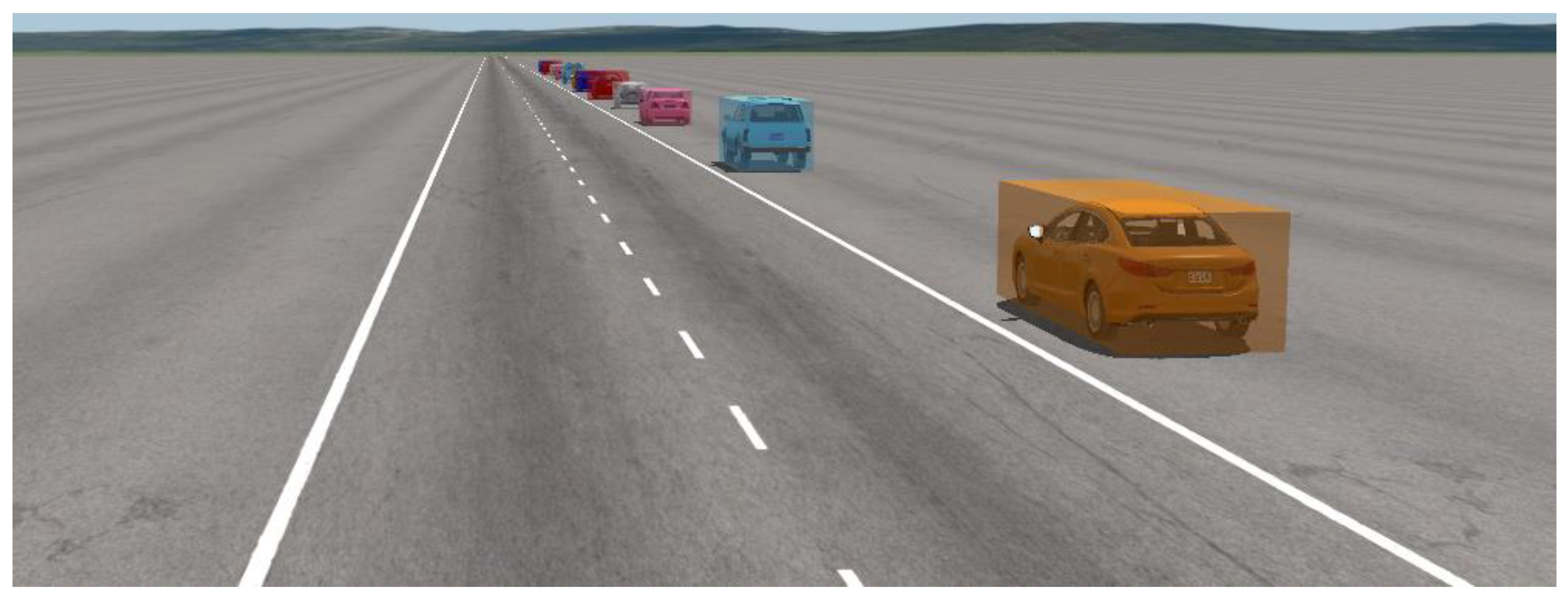
Figure 2.
GOACA three-lane highway test course.
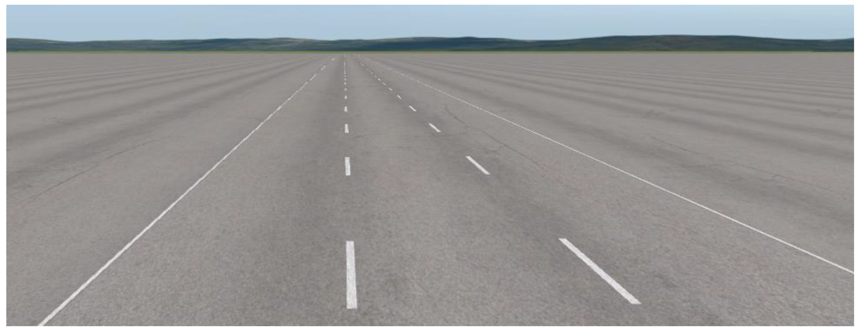
Figure 3.
D-Class Minivan ARO used for tests 1) through 3) in the GOACA (CarSim 2021.0).
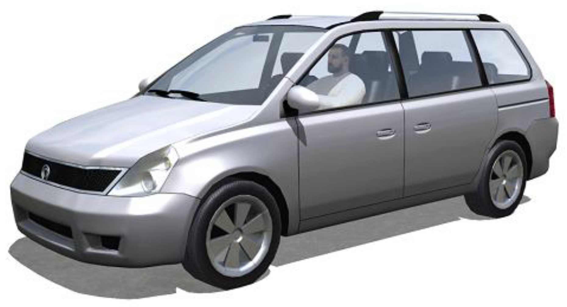
Figure 4.
ARO car used in test 4a) of the GOACA (CarSim 2021.0).
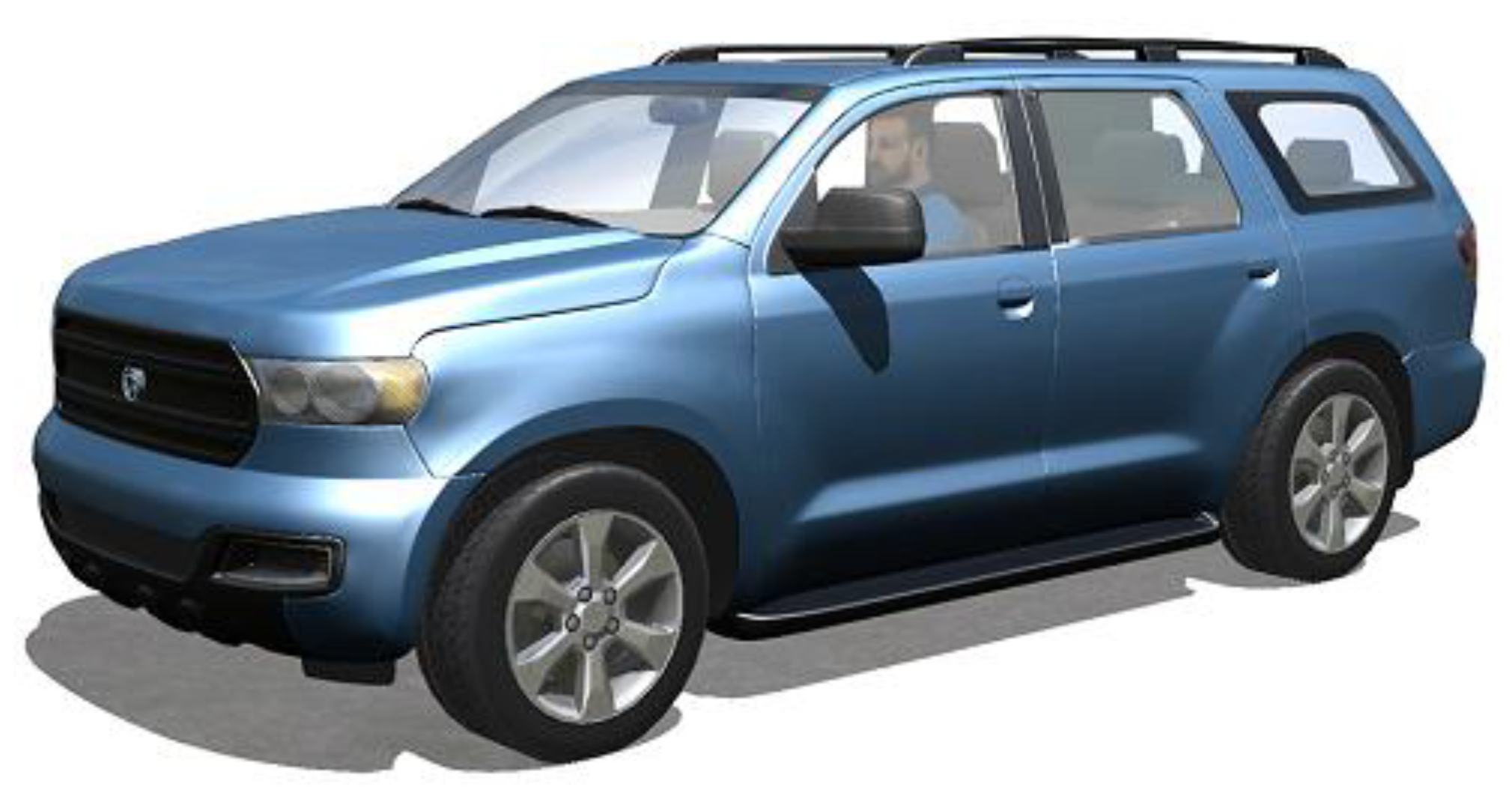
Figure 5.
AV with front, left, and right-facing sensors.
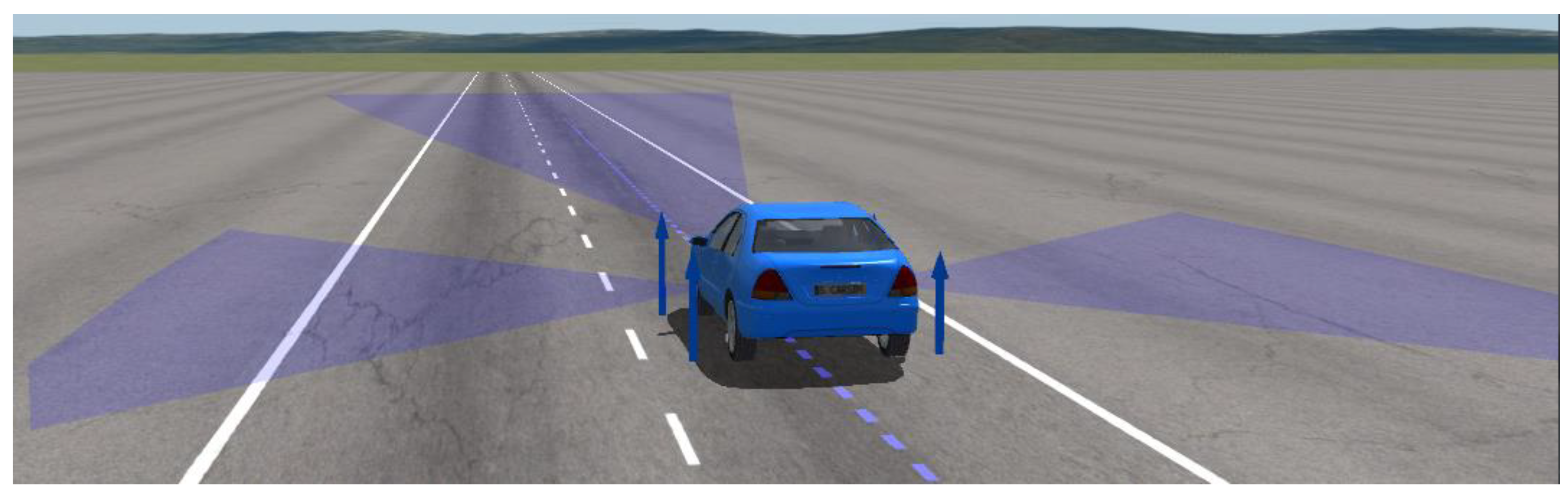
Figure 6.
Top view of Cut-In scenario, with AV (blue), ARO (red), and potential traffic in adjacent lane (orange).
Figure 6.
Top view of Cut-In scenario, with AV (blue), ARO (red), and potential traffic in adjacent lane (orange).
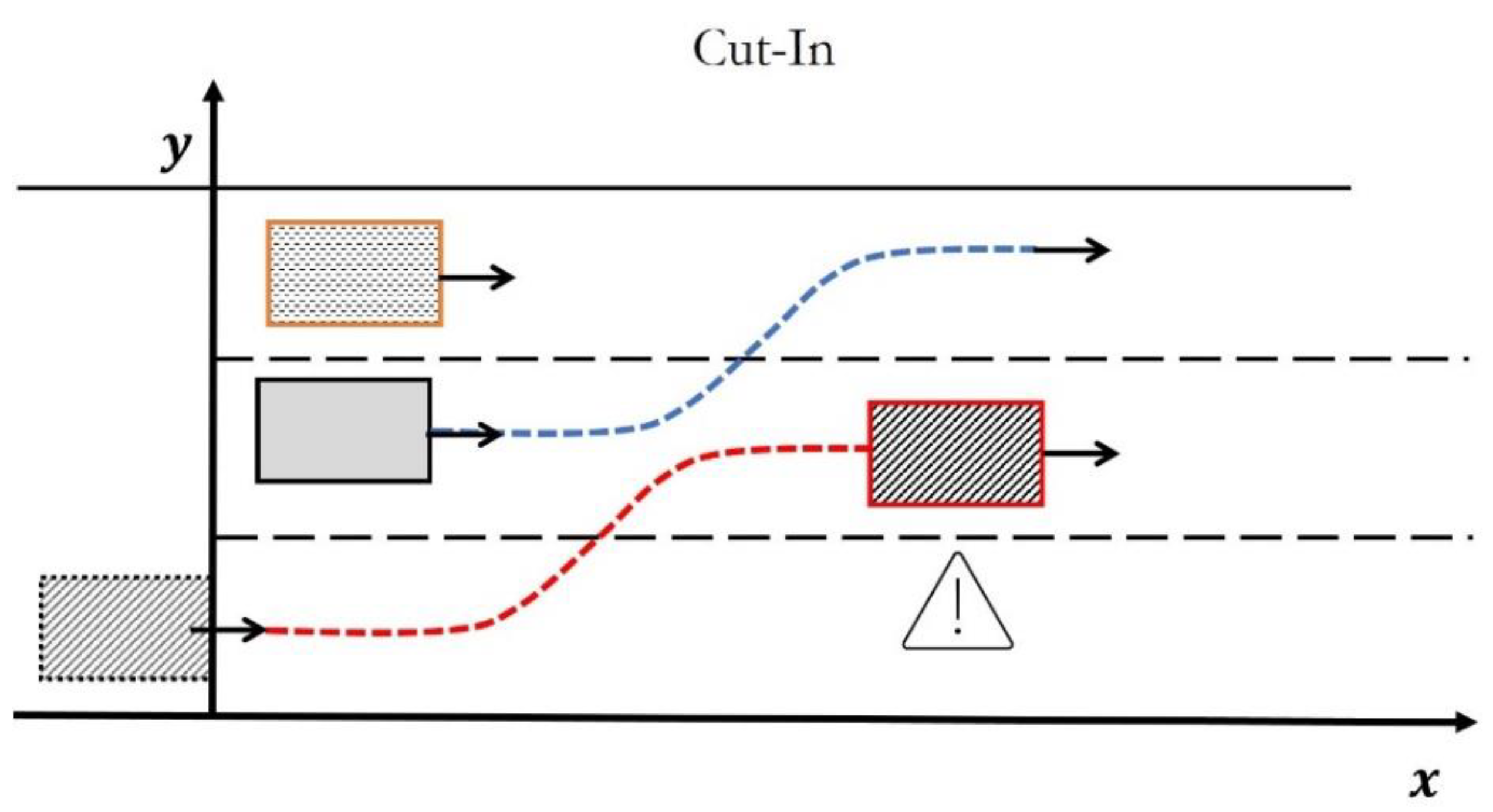
Figure 7.
Example fifth-order polynomial input used for the Cut-In ARO, traveling at 60 km/h.
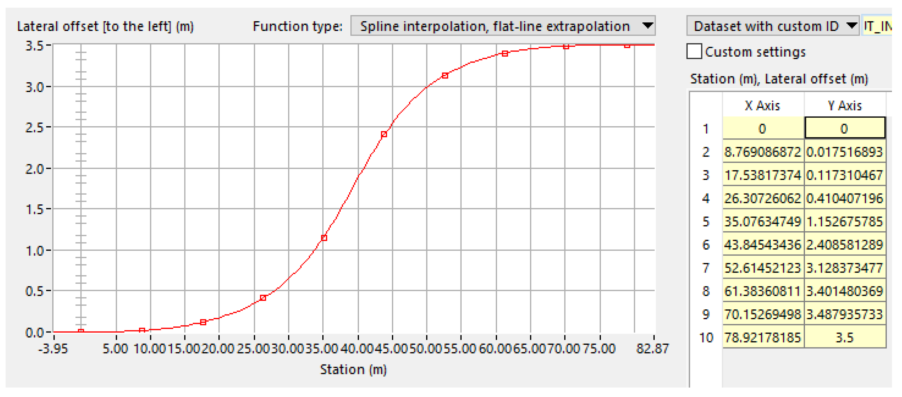
Figure 8.
CarSim visualization of the initial encroachment of the ARO into AV lane-of-travel, 120 km/h example.
Figure 8.
CarSim visualization of the initial encroachment of the ARO into AV lane-of-travel, 120 km/h example.
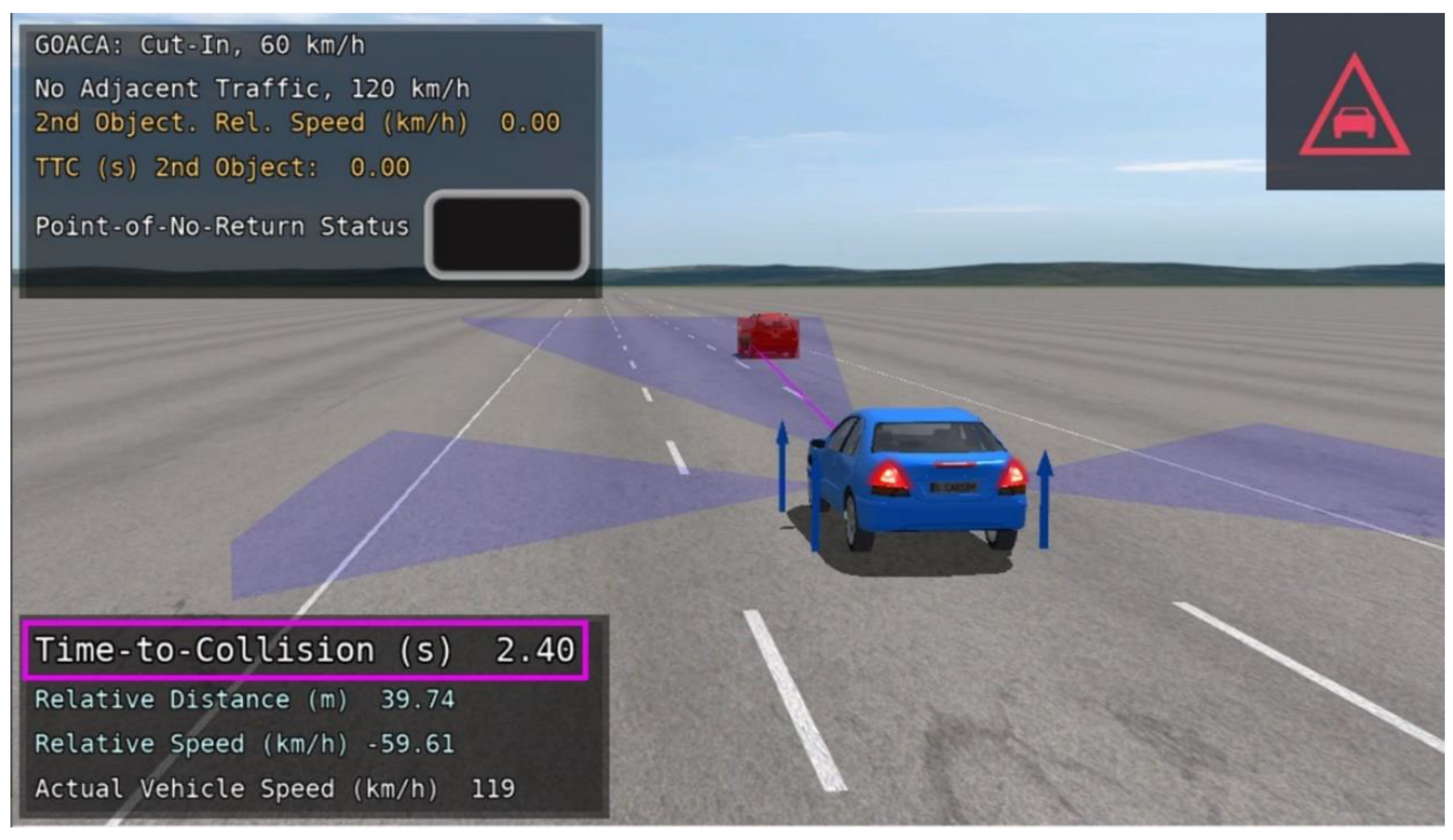
Figure 9.
Top view of Cut-Out-and-Reveal scenario, with AV (blue), ARO (red), and potential traffic in adjacent lane (orange).
Figure 9.
Top view of Cut-Out-and-Reveal scenario, with AV (blue), ARO (red), and potential traffic in adjacent lane (orange).
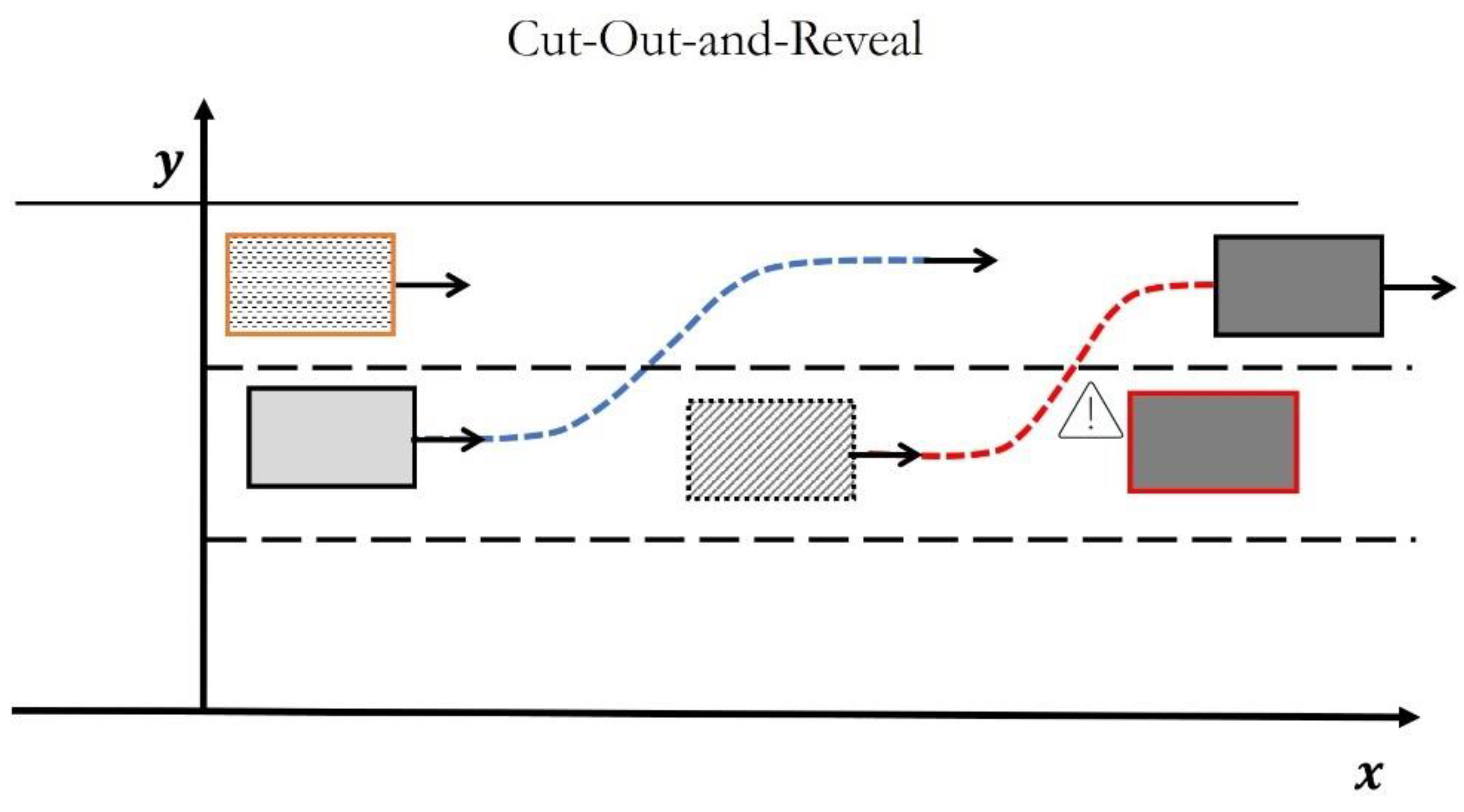
Figure 10.
CarSim visualization of the AV perceiving the ARO cutting out of the middle lane and the stopped vehicle revealed.
Figure 10.
CarSim visualization of the AV perceiving the ARO cutting out of the middle lane and the stopped vehicle revealed.
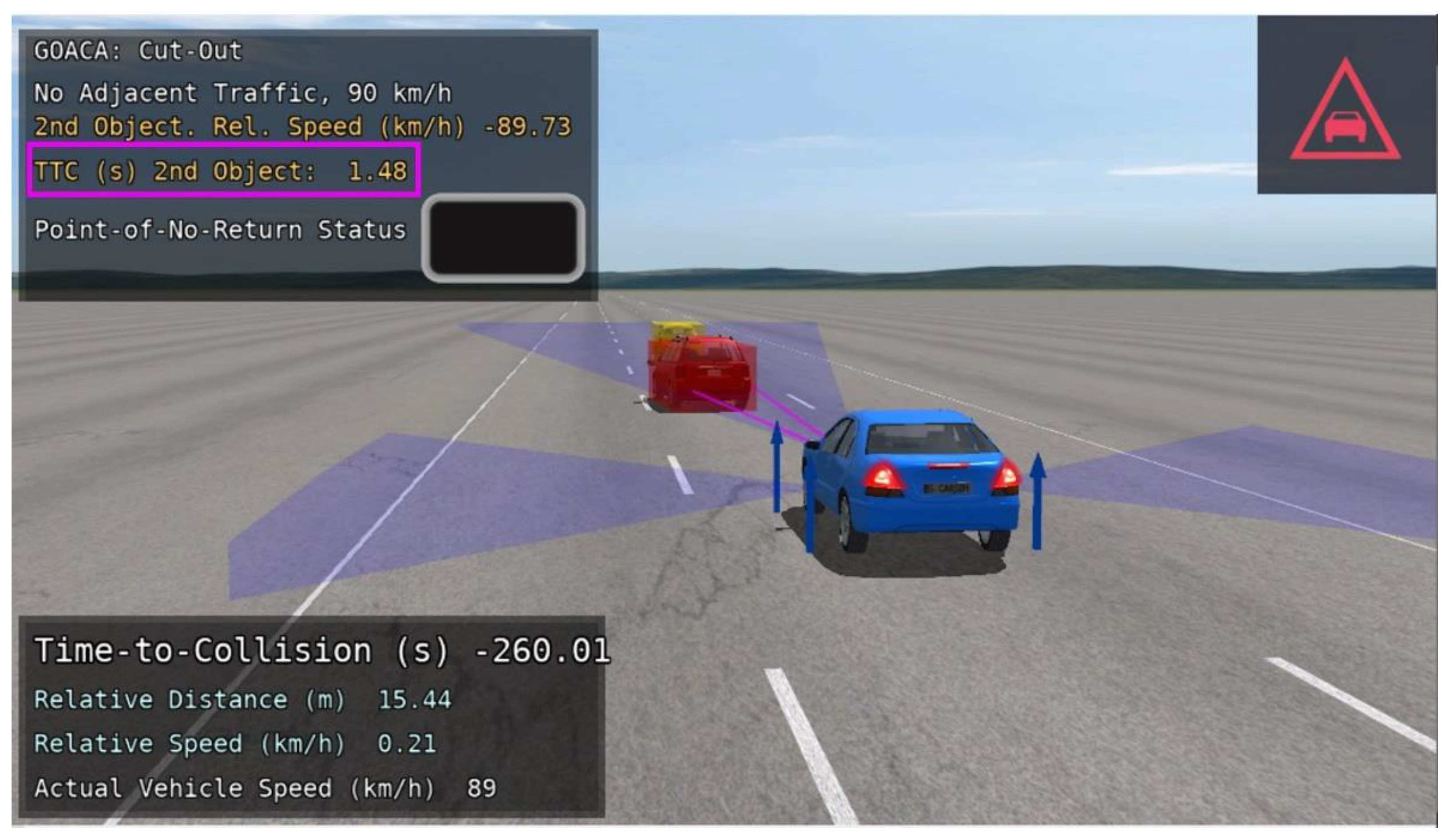
Figure 11.
Cut-In scenario with one additional traffic vehicle in the left adjacent lane to the AV.
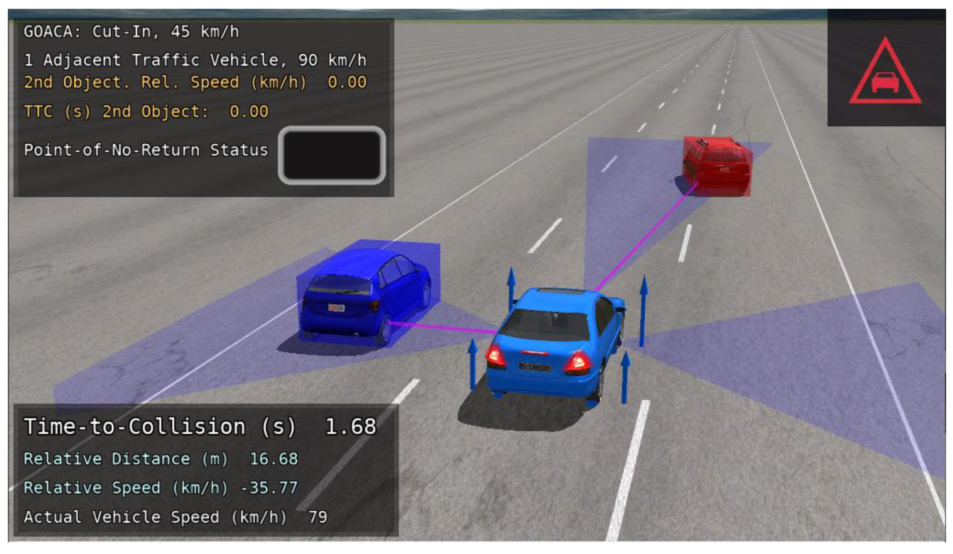
Figure 12.
Cut-Out scenario with two additional traffic vehicles in the left adjacent lane to the AV.
Figure 12.
Cut-Out scenario with two additional traffic vehicles in the left adjacent lane to the AV.

Figure 13.
Median Intersection Design for Rural High-Speed Divided Highways top view illustration [28].
Figure 13.
Median Intersection Design for Rural High-Speed Divided Highways top view illustration [28].
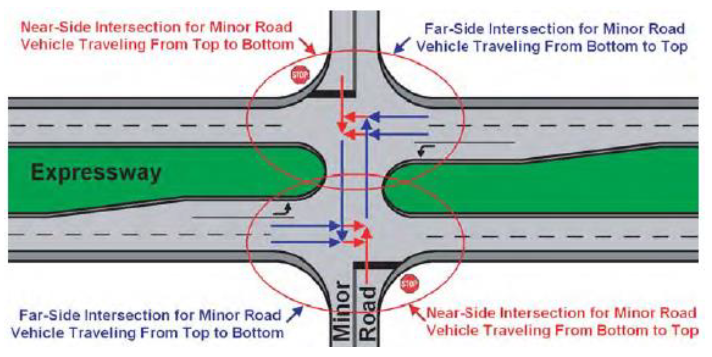
Figure 14.
3D rendering of divided rural highway with intersection [29].
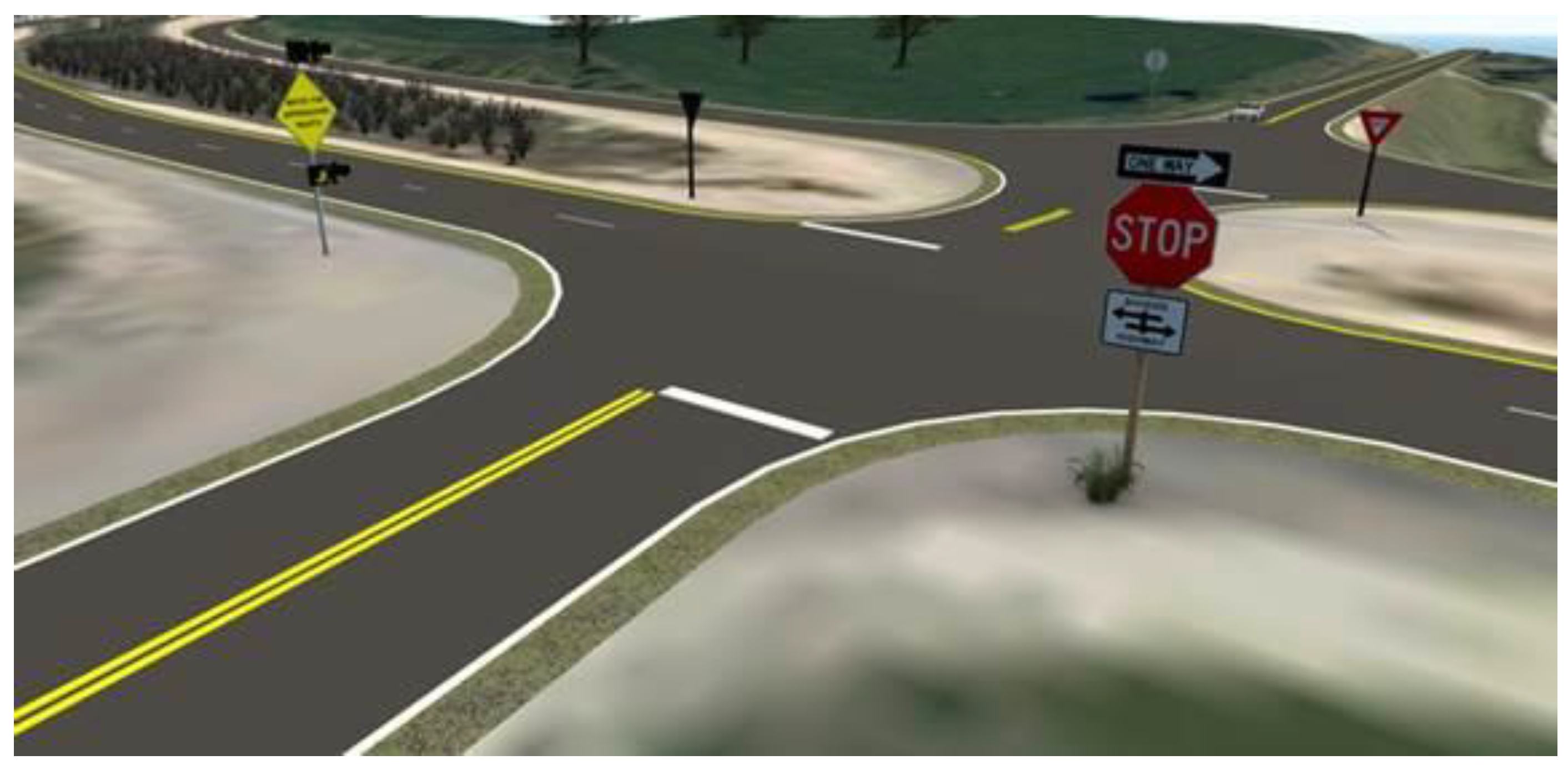
Figure 15.
Illustration of GOACA proving ground setup for the Perpendicular Encroachment on the Divided Rural Highway with Intersection scenario; included vehicles are the AV (blue), ARO car (red), potential traffic (orange), and parked cars (black).
Figure 15.
Illustration of GOACA proving ground setup for the Perpendicular Encroachment on the Divided Rural Highway with Intersection scenario; included vehicles are the AV (blue), ARO car (red), potential traffic (orange), and parked cars (black).
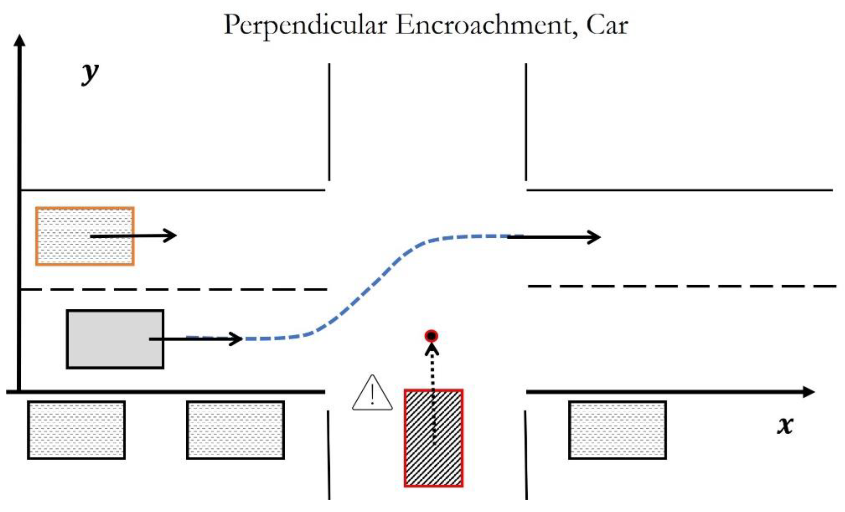
Figure 16.
Illustration of GOACA proving ground setup for the Perpendicular Encroachment on the Divided Rural Highway with Intersection scenario; included vehicles are the AV (blue), ARO bicyclist (red), potential traffic (orange), and parked cars (black).
Figure 16.
Illustration of GOACA proving ground setup for the Perpendicular Encroachment on the Divided Rural Highway with Intersection scenario; included vehicles are the AV (blue), ARO bicyclist (red), potential traffic (orange), and parked cars (black).

Figure 17.
(Left) Top-down view of rural highway and crossing scenario when semi-autonomous Uber vehicle (right) fatally struck bicyclist [30].
Figure 17.
(Left) Top-down view of rural highway and crossing scenario when semi-autonomous Uber vehicle (right) fatally struck bicyclist [30].
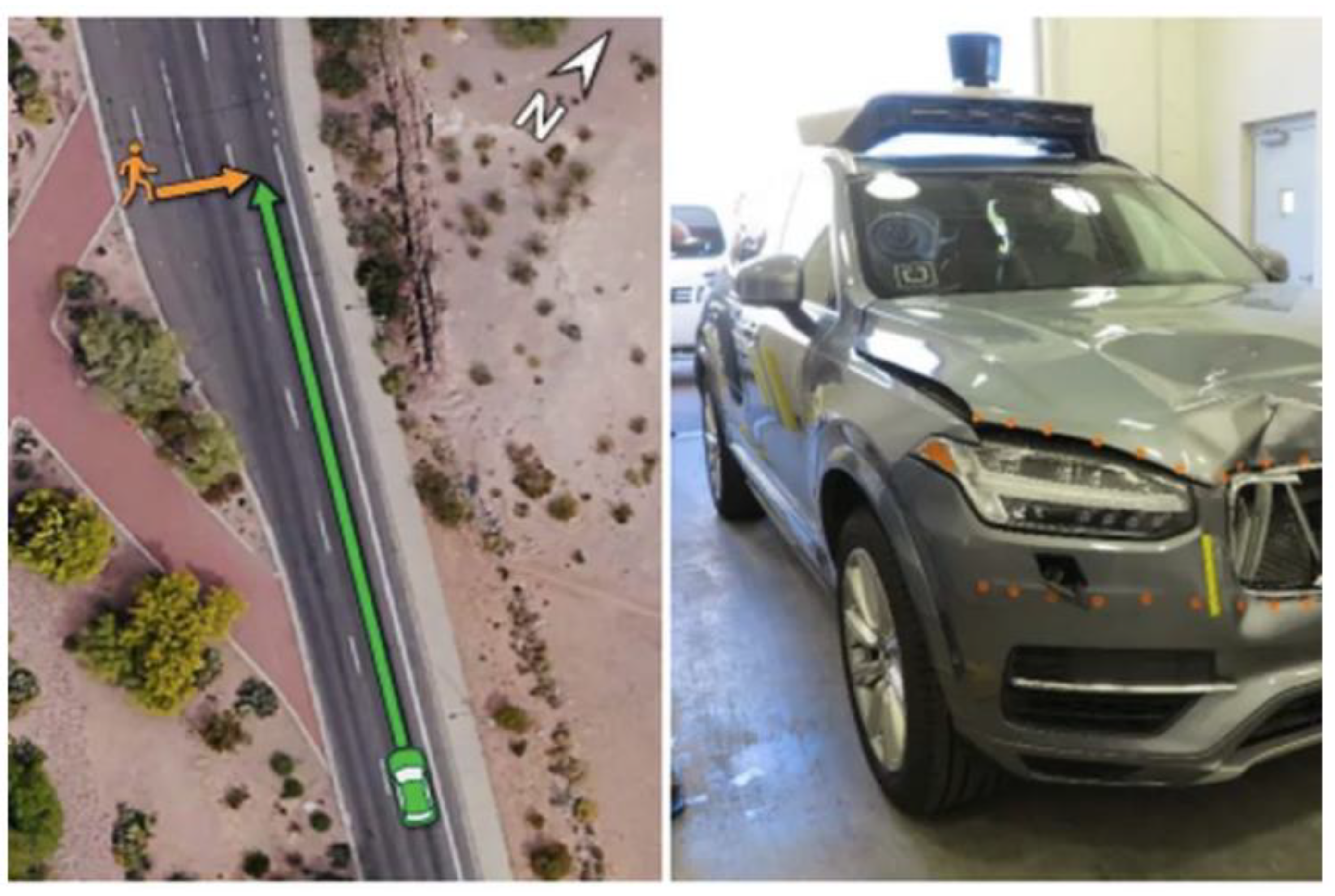
Figure 18.
CarSim visualization of the Perpendicular Encroachment on the Divided Rural Highway with Intersection scenario with car ARO.
Figure 18.
CarSim visualization of the Perpendicular Encroachment on the Divided Rural Highway with Intersection scenario with car ARO.
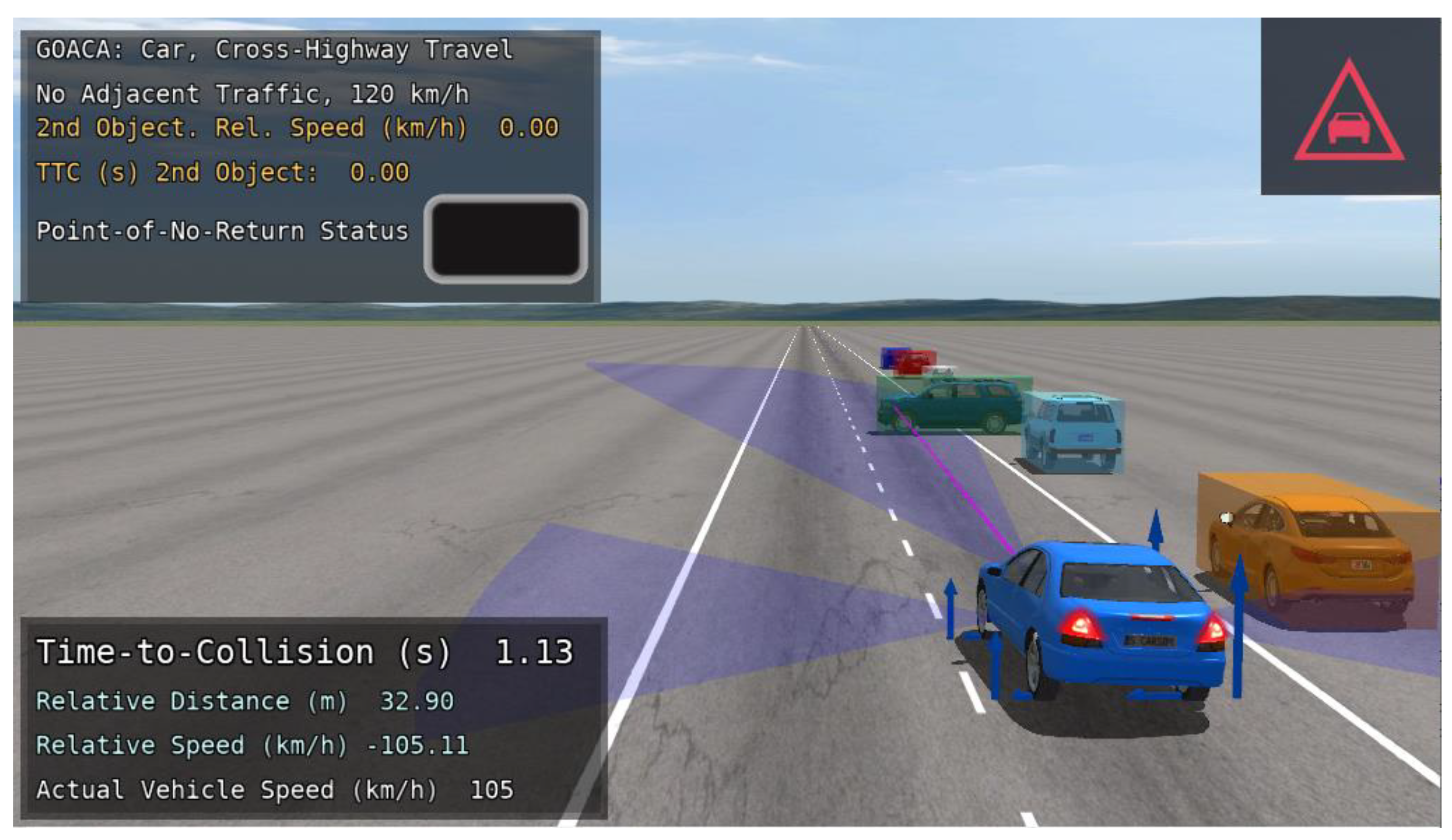
Figure 19.
CarSim visualization of the Perpendicular Encroachment on the Divided Rural Highway with Intersection scenario with bicyclist ARO.
Figure 19.
CarSim visualization of the Perpendicular Encroachment on the Divided Rural Highway with Intersection scenario with bicyclist ARO.
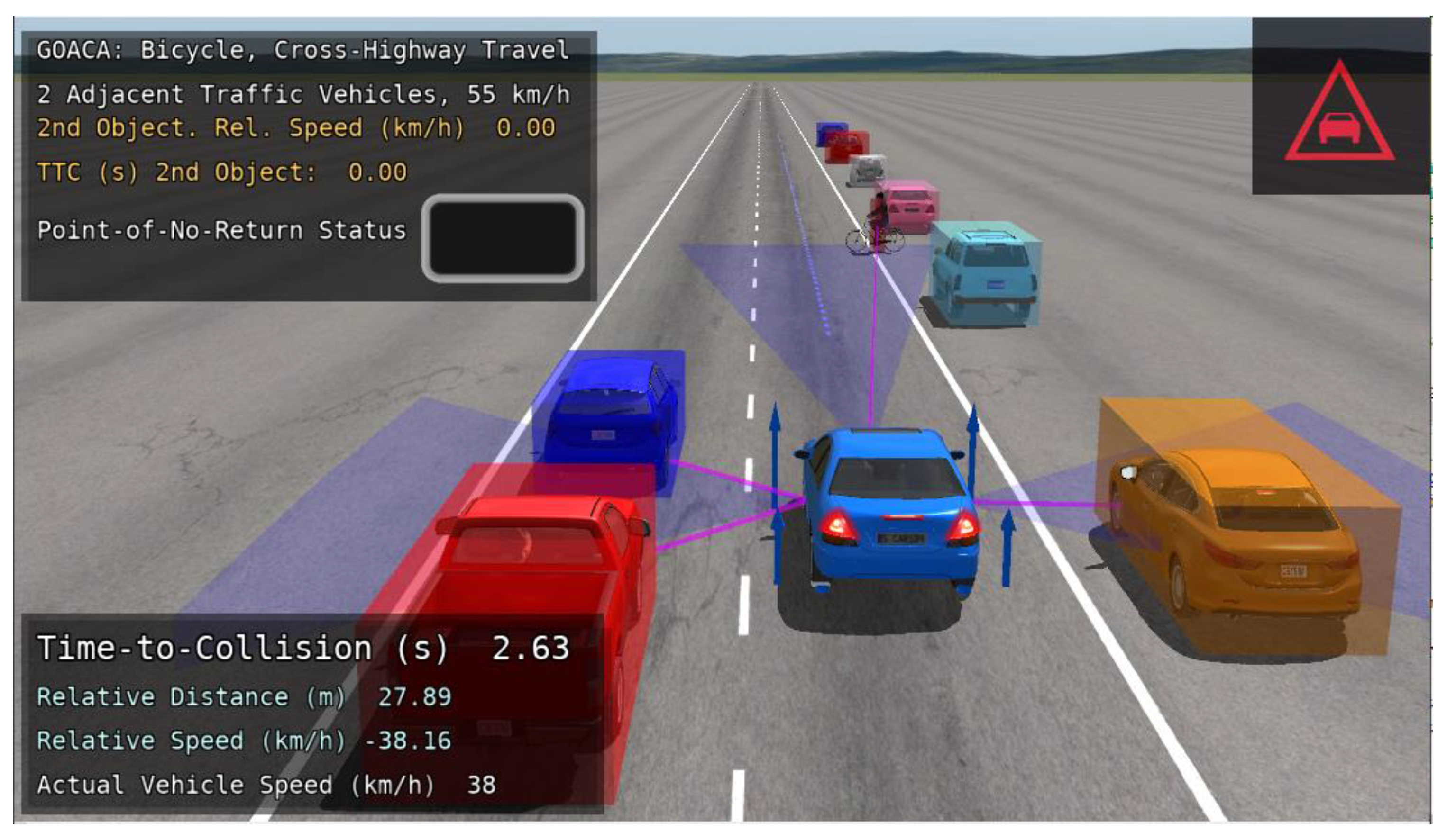
Figure 20.
Example of the AV slowing down to avoid colliding with a Cut-In ARO while not performing a lane change, due to adjacent traffic.
Figure 20.
Example of the AV slowing down to avoid colliding with a Cut-In ARO while not performing a lane change, due to adjacent traffic.
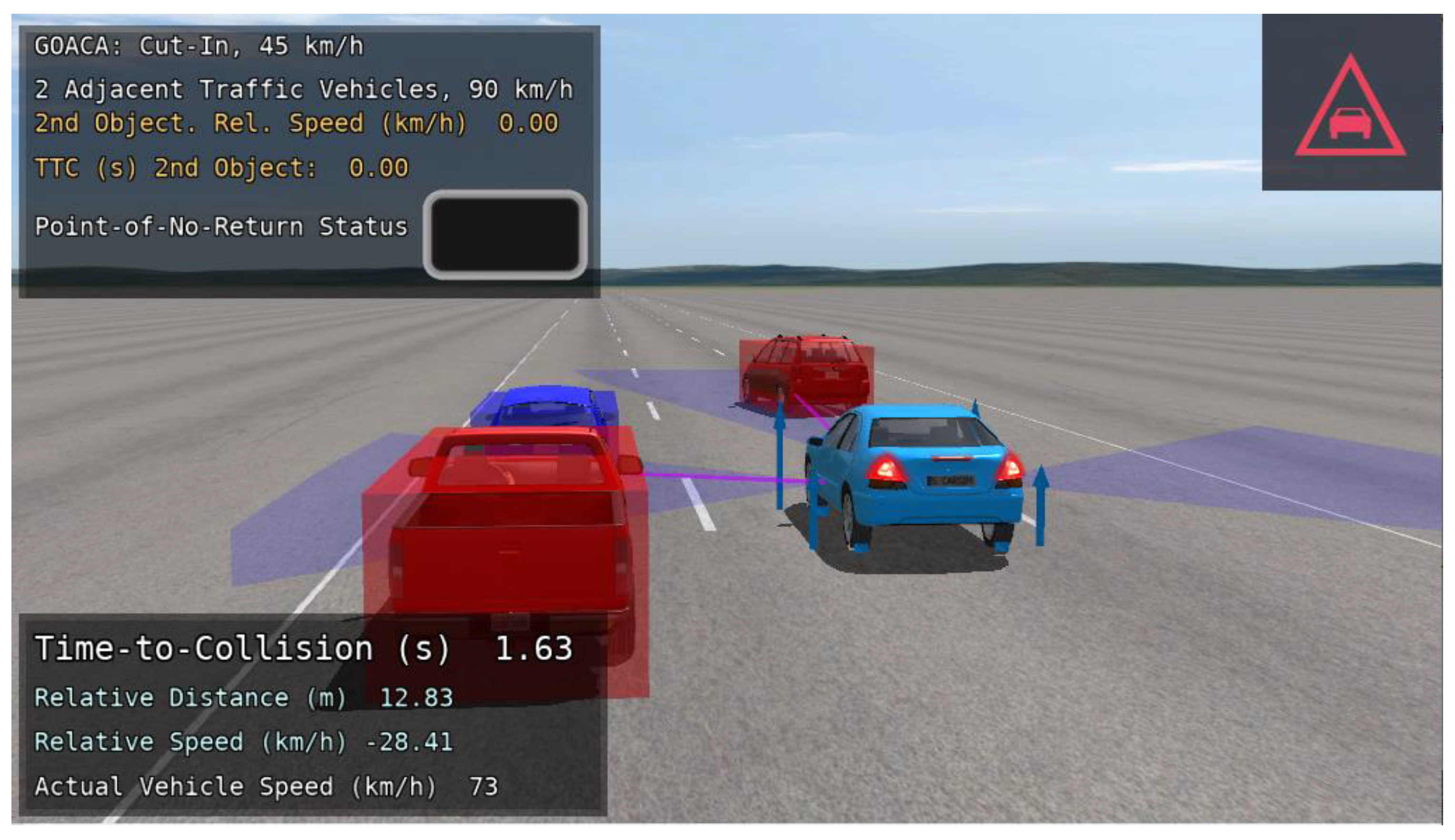
Figure 21.
AV performing a lane change maneuver after braking enough to allow two adjacent traffic vehicles to pass, in a Cut-In test.
Figure 21.
AV performing a lane change maneuver after braking enough to allow two adjacent traffic vehicles to pass, in a Cut-In test.
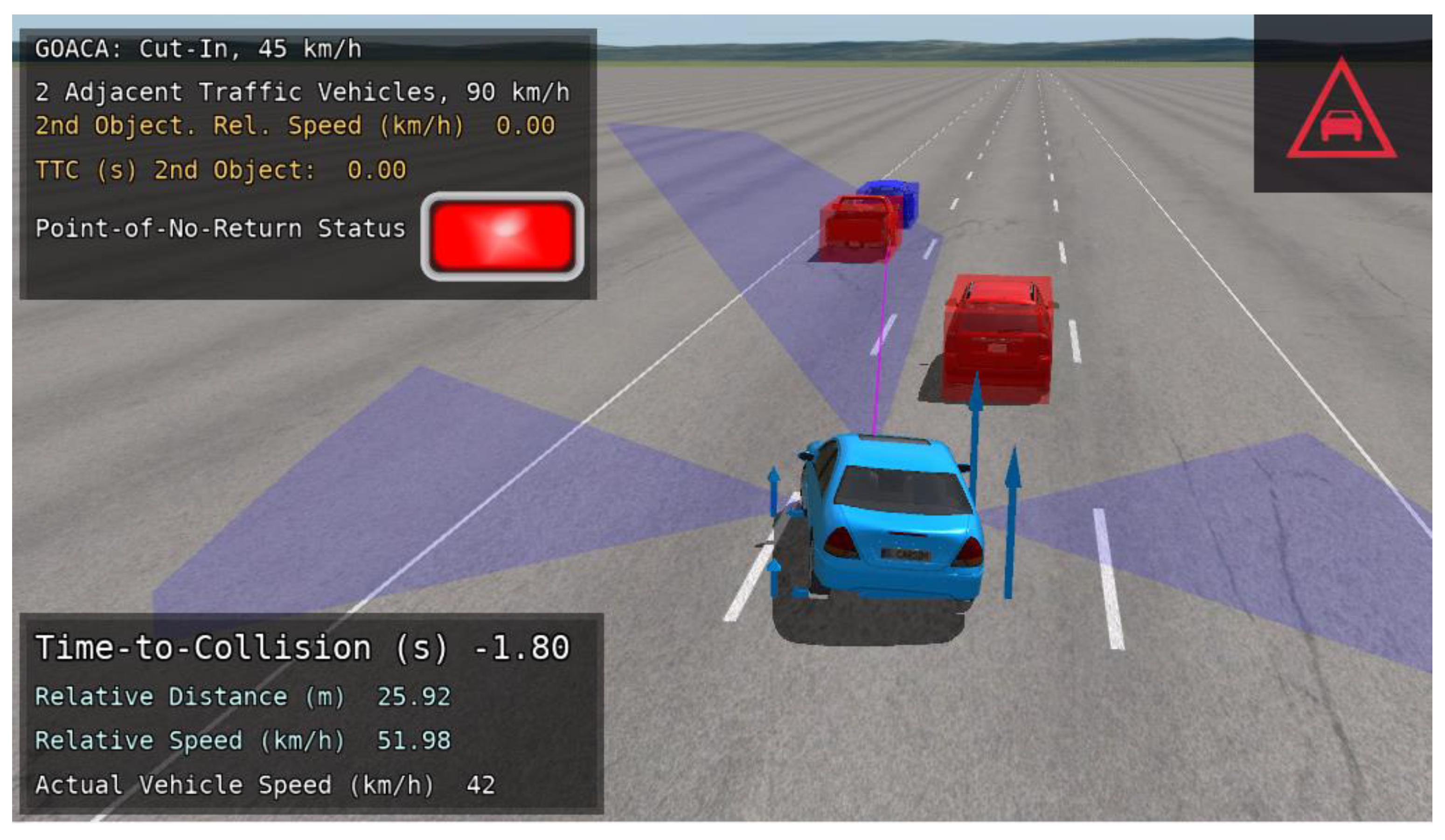
Figure 22.
AV returning to the original lane successfully after the lane-change maneuver in the Cut-In test.
Figure 22.
AV returning to the original lane successfully after the lane-change maneuver in the Cut-In test.
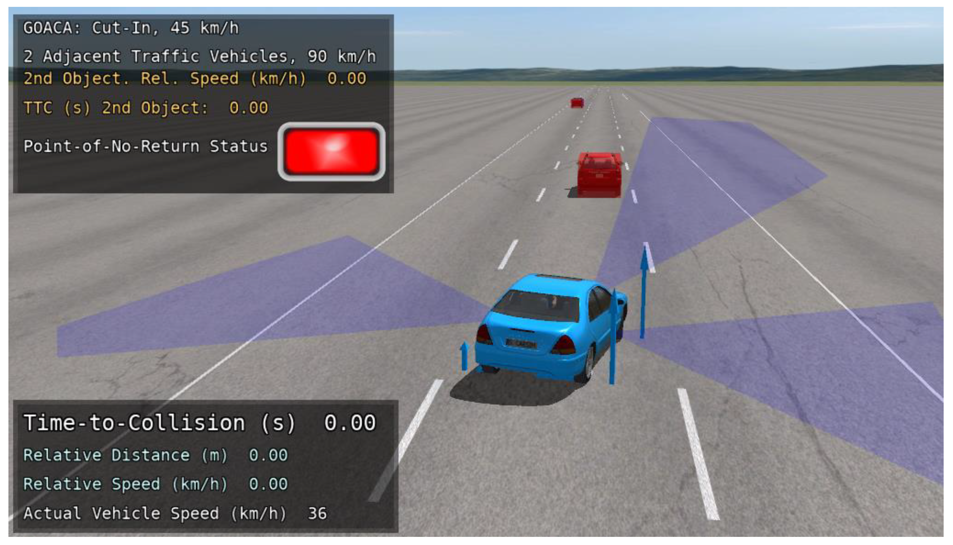
Figure 23.
AV avoiding a perpendicularly encroaching ARO and one adjacent traffic vehicle via braking, then lane-change maneuver.
Figure 23.
AV avoiding a perpendicularly encroaching ARO and one adjacent traffic vehicle via braking, then lane-change maneuver.
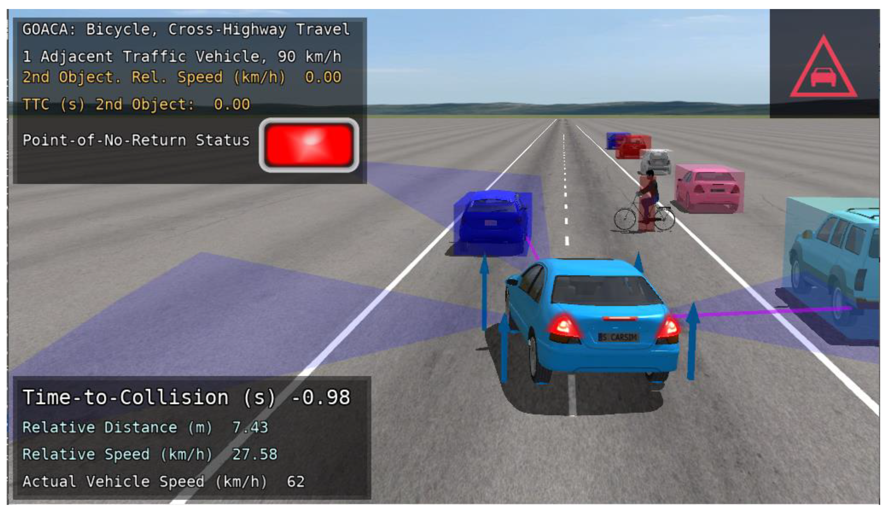
Figure 24.
AV full stop to successfully avoid colliding with a perpendicularly encroaching ARO and two adjacent traffic vehicles.
Figure 24.
AV full stop to successfully avoid colliding with a perpendicularly encroaching ARO and two adjacent traffic vehicles.
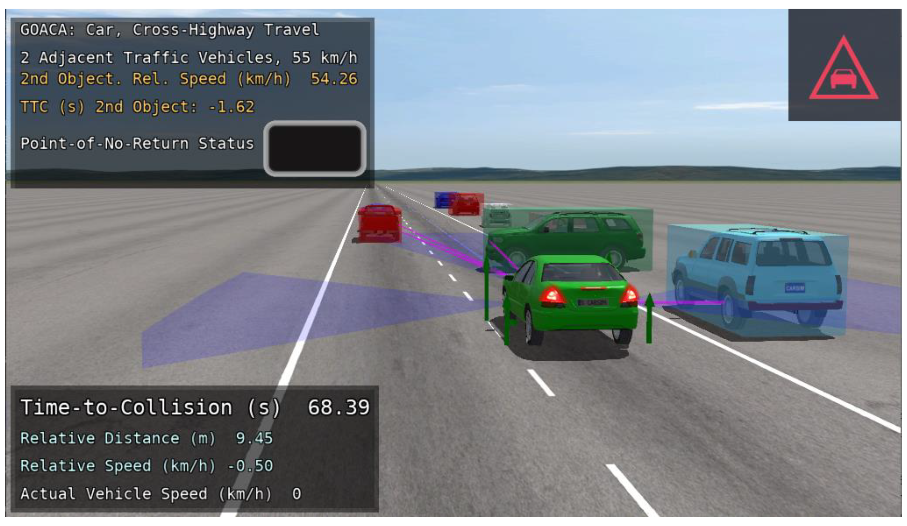

Table 1.
Test matrix for the Slow-to-Stop test.
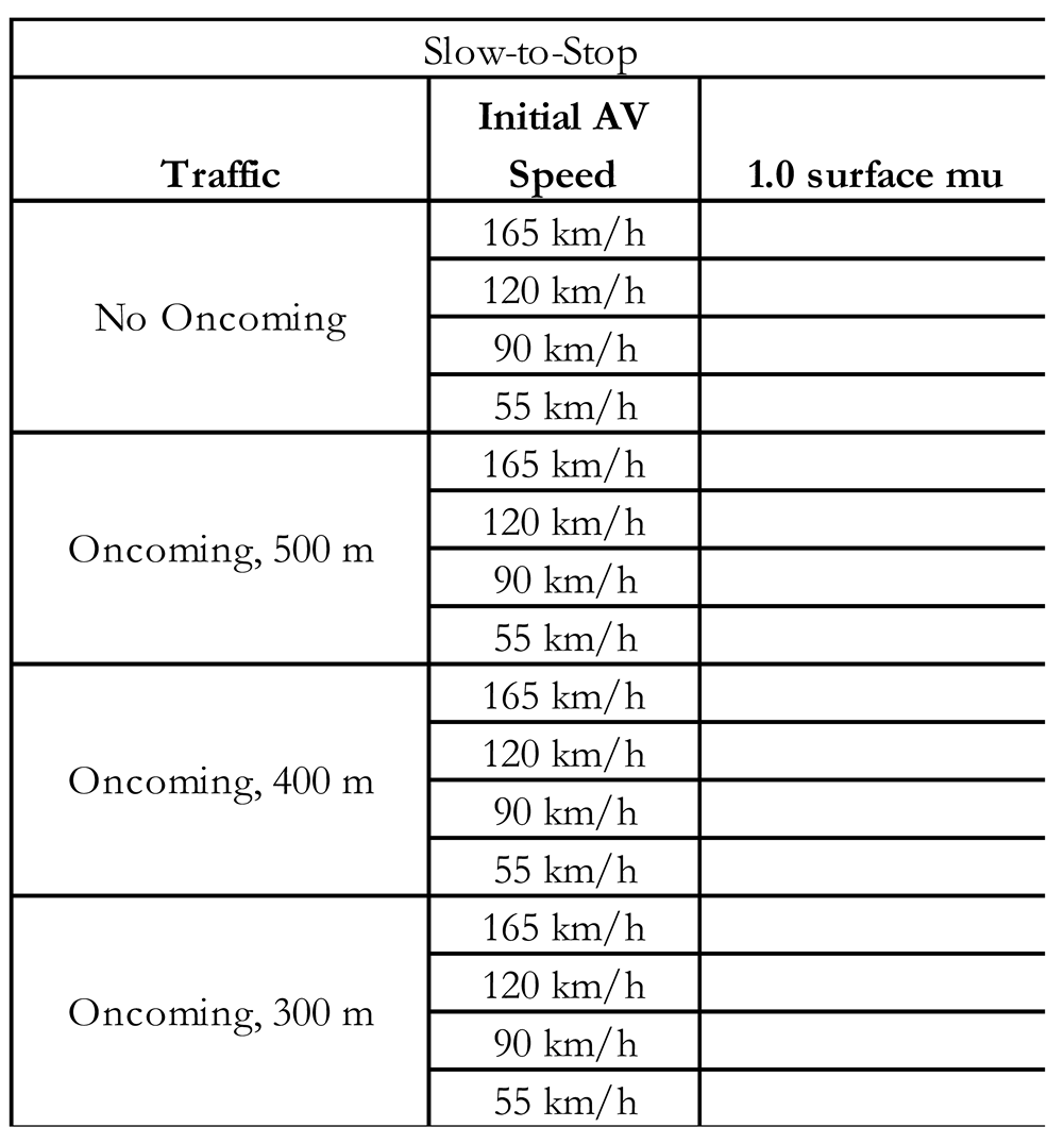 |
Table 2.
Test matrix for the Cut-In, Cut-Out-and-Reveal, and Perpendicular Encroachment tests.
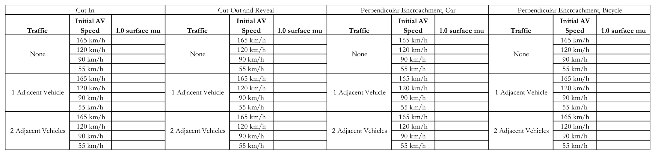 |
Table 3.
Parameters for entry Cut-In ARO trajectories, along with target lateral acceleration during
the maneuver and TTC upon entering the lane of the AV.
Table 3.
Parameters for entry Cut-In ARO trajectories, along with target lateral acceleration during
the maneuver and TTC upon entering the lane of the AV.
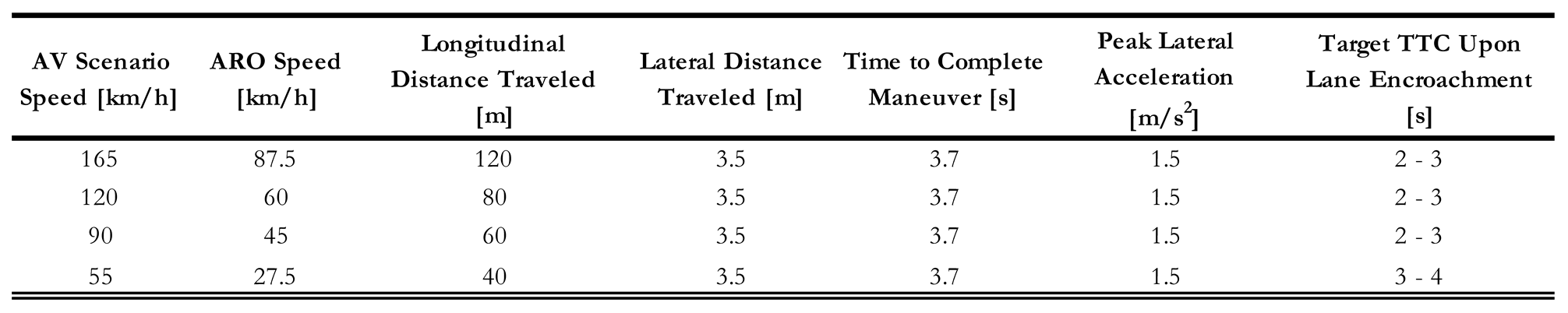 |
Table 4.
Parameters for entry Cut-Out ARO trajectories, along with target lateral acceleration during
the maneuver and TTC upon the AV’s perception of the stopped vehicle.
Table 4.
Parameters for entry Cut-Out ARO trajectories, along with target lateral acceleration during
the maneuver and TTC upon the AV’s perception of the stopped vehicle.
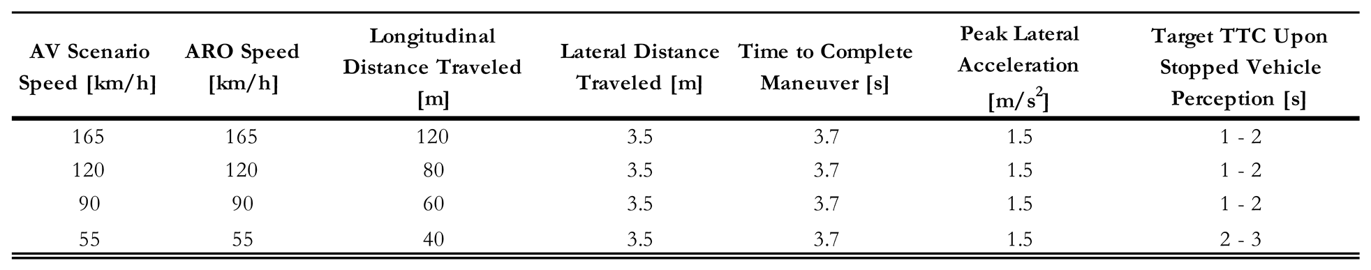 |
Table 5.
Start distance, start and stop trigger distances, and speed of travel for the ARO in the
Perpendicular Encroachment on the Divided Rural Highway with Intersection GOACA tests.
Table 5.
Start distance, start and stop trigger distances, and speed of travel for the ARO in the
Perpendicular Encroachment on the Divided Rural Highway with Intersection GOACA tests.
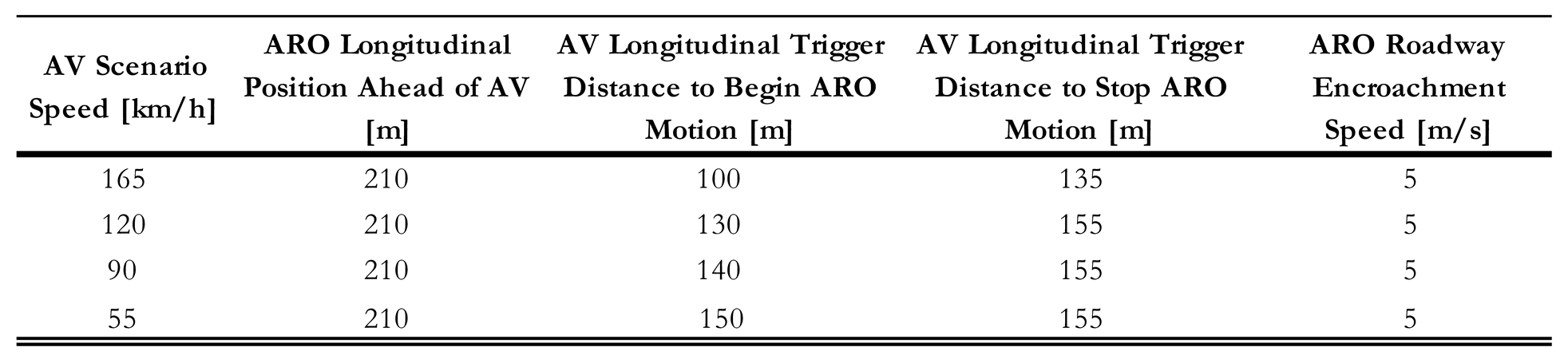 |
Table 6.
GOACA Scoring Rubric for the dry testing surface.
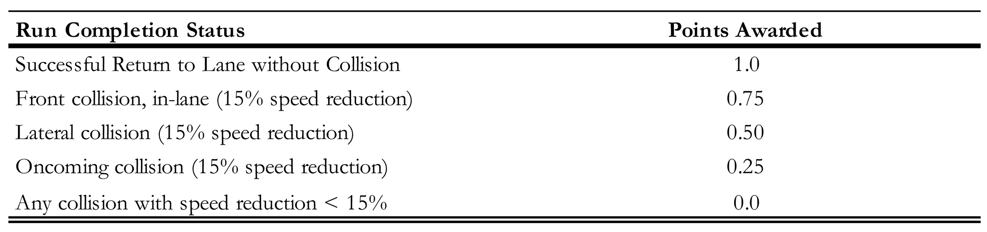 |
Table 7.
Slow-to-Stop GOACA Test Scores.
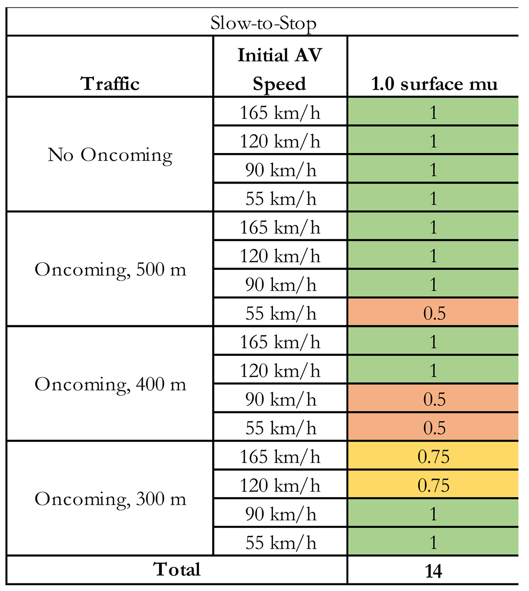 |
Table 8.
Full Slow-to-Stop test results on multiple surface friction levels.
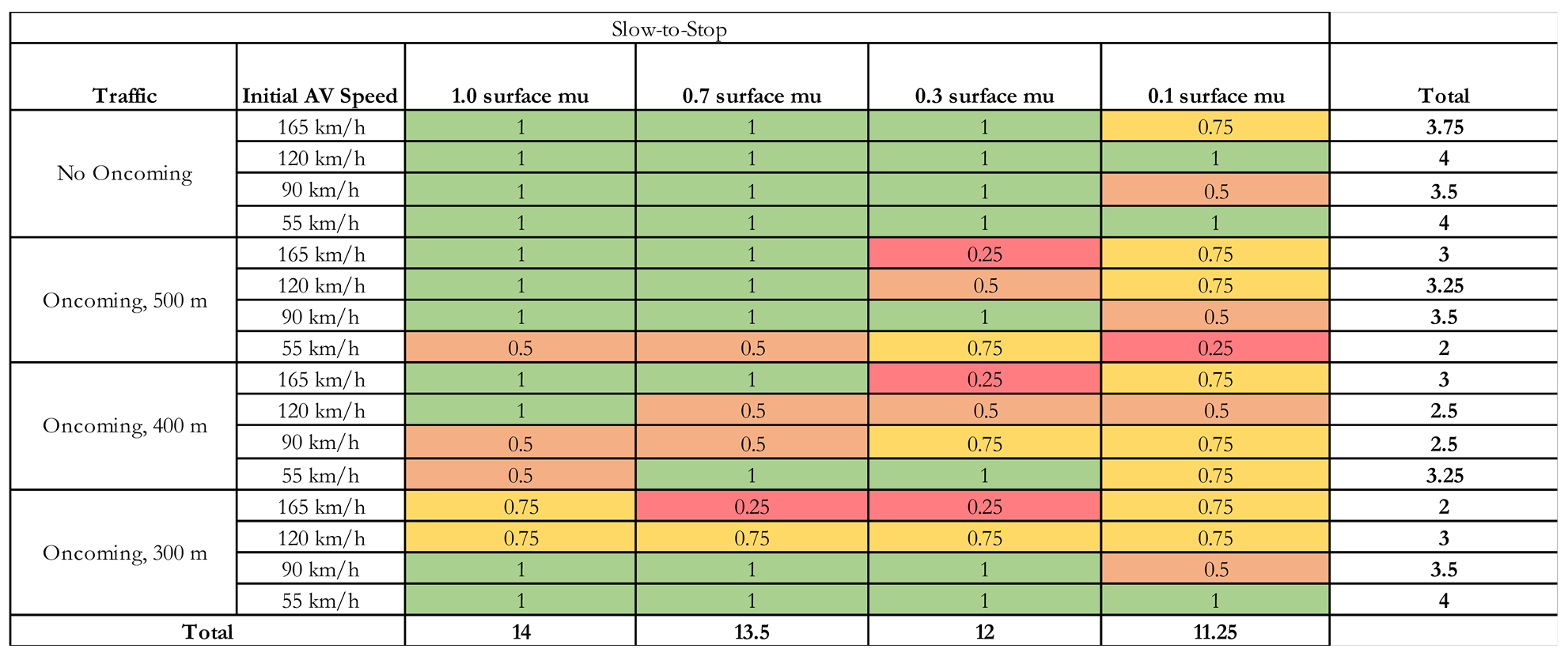 |
Table 9.
Required speed reduction % during GOACA tests with collisions for various surface fiction
levels.
Table 9.
Required speed reduction % during GOACA tests with collisions for various surface fiction
levels.
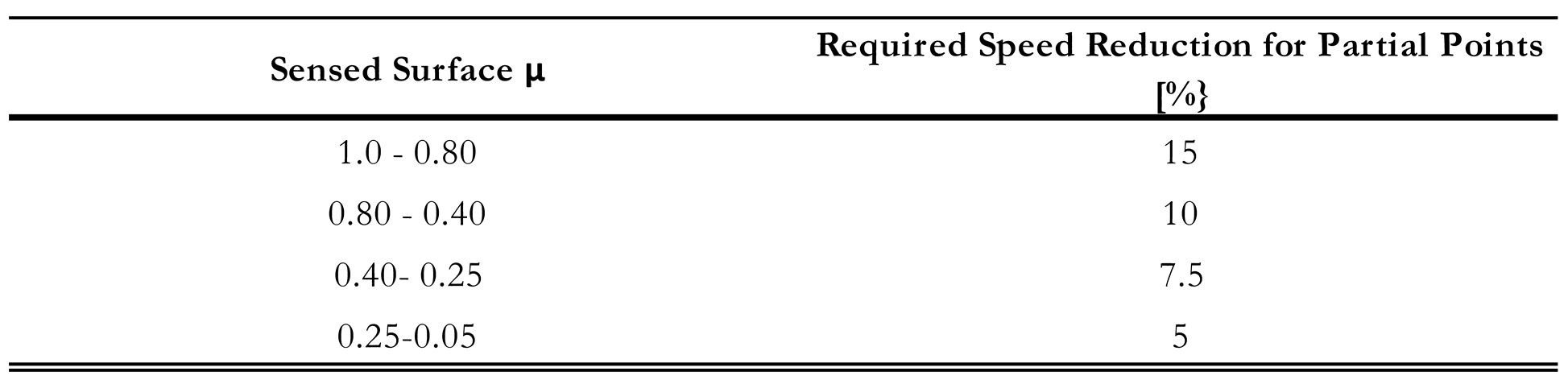 |
Table 10.
Cut-In and Cut-Out-and-Reveal GOACA Test Scores.
 |
Table 11.
Perpendicular Encroachment Car and Bicycle GOACA Test Scores.
 |
Disclaimer/Publisher’s Note: The statements, opinions and data contained in all publications are solely those of the individual author(s) and contributor(s) and not of MDPI and/or the editor(s). MDPI and/or the editor(s) disclaim responsibility for any injury to people or property resulting from any ideas, methods, instructions or products referred to in the content. |
© 2024 by the authors. Licensee MDPI, Basel, Switzerland. This article is an open access article distributed under the terms and conditions of the Creative Commons Attribution (CC BY) license (http://creativecommons.org/licenses/by/4.0/).
Copyright: This open access article is published under a Creative Commons CC BY 4.0 license, which permit the free download, distribution, and reuse, provided that the author and preprint are cited in any reuse.


