Submitted:
14 December 2023
Posted:
15 December 2023
You are already at the latest version
Abstract
Ceramic composites have good strength, fracture toughness and hardness characteristics and are widely used in industry, medicine. The properties of ceramic composites can be controlled at the production stage by setting the internal structure. This is made possible by the development of additive manufacturing. However, not all properties are well understood, especially dynamic fracture resistance and fracture toughness. In order to predict the mechanical behavior of ceramic composites in the manufacturing phase with a controlled structure under dynamic loads, it is convenient to use methods of numerical analysis. The aim of this work was to investigate the influence of loading speed and internal structure on dynamic resistance and fracture toughness of ATZ nanocomposites. Within the framework of the study physical and mathematical model that is used in computational mechanics of materials is developed. In the paper is shown the influence of the loading rate on the strain rate in the region of the shock transition for materials based on ZrO2 - Al2O3 system. The research shows nonlinear effects under intense dynamic loads in the shown composite materials are bound up with either the processes of self-organisation of deformation modes at the mesoscopic level or the occurrence of martensitic phase transformations in matrix volumes adjacent to the strengthening particles.
Keywords:
dynamic loading
; ceramic materials
; composite structure
; transformation hardening
; additive technologies
1. Introduction
Ceramic composites based on alumina and zirconia systems are a class of functional materials characterized not only by strength properties, but also by chemical and thermal stability. They are also used in biological applications, to manufacture electric, magnetic and other products [1,2]. One of the best known and actively studied classes of functional ceramic composites with transformation hardening are ATZ composites (zirconia reinforced with alumina), a matrix of zirconia. They are used not only in engineering as structural materials [3] for the manufacture of cutting tools and wear parts, but also in medicine (especially in orthopedic prostheses). When preparing such composites, the high temperature phase (tetragonal or cubic) is partially stabilized by small additional impurities of Y2O3, MgO and CeO oxides [4]. The tetragonal phase can undergo a martensitic phase transition to a monoclinic phase under the influence of tensile stresses in the region of microconcentrators (at the boundaries of the particles of the hardening phases, at the tops of cracks, etc.). The transition from the tetragonal to the monoclinic phase is accompanied by a 4% increase in the volume of the phase [4,5]. At a pressure of 12.5 GPa, the tetragonal phase becomes monoclinic [6]. The phase transition is accompanied by the development of shear and volume deformations. These deformations provide stress relaxation and crack surface closure. The local martensitic transformation t → m in ZrO2 contributes to closing crack edges or collapsing micropores, thereby reducing the intensity of stress concentrators near defects. This effect, known as transformational hardening [7], stabilizes existing or newly formed microcracks while maintaining the level of external loading. Realizing the hardening effect makes it possible to achieve strength properties (crack resistance, strength) of ceramic materials comparable to those of structural alloys. It should be noted that the ATZ composites obtained by means of additive technologies are particularly interesting for study, have high crack resistance and strength under static loading conditions [8,9], and have high prospects of application in industry. Remember that ceramics are generally the most difficult materials to work with [10], and ATZ composites are no exception. Conventional bulk ceramic production techniques are very primitive and severely limited by mold geometry. In addition to the limited geometric freedom in the manufacturing process, the same problem exists in the post-heat treatment process, as it is extremely difficult to change their geometry by machining or other subtractive manufacturing methods. This geometric constraint imposed by the manufacturing process has been studied for many years.
The most promising method to mitigate this problem is additive manufacturing (AM) [11,12]. The geometric limitations inherent in traditional manufacturing methods can be eliminated by introducing additive manufacturing for the fabrication of CE-RAMIC composite structures. In recent years, extensive research efforts have been devoted to the development and demonstration of the feasibility of the use of rational geometry design to tune the properties of various structures [13,14,15,16]. On the other hand, the mechanical properties of ceramic composite materials that undergo transformation hardening under energetic influences are not well understood.
The evaluation of the dynamic behavior of such composites is a serious problem. It can be solved by computer modeling methods. This has been due to the lack of understanding of the processes involved in the evolution of the structure of composite materials under dynamic loading and the lack of adequate models of the mechanical behavior of composite materials which can take account of the characteristics of the deformation process, phase transitions, damage development and destruction of the material. The aim of this work was to develop an approach from the point of view of computational mesomechanics to study the mechanical behavior of ceramic composites with a hardened transformation matrix under dynamic effects. This approach will make it possible to create intelligent ceramic composite materials by means of additive technologies that will operate in a wide range of loading speeds.
2. Materials and Methods
In order to predict the mechanical behavior of ceramic composites with a transformation-hardenable matrix under intense dynamic effects, the computational mechanics of materials has been used in this study [17]. Numerical simulation in Lagrangian coordinates using explicit integration schemes is a commonly-utilized tool for studying features of dynamic mechanical behavior of materials, including fracture dynamics. The finite element method (FEM) [18,19] is a widely used "Lagrangian" numerical method for solving such problems. With its well-developed mathematical tools, this method enables the implementation of complex rheological models to analyze the mechanical response of materials and solve intricate problems related to the mechanics of deformable solids. It is important to note that utilization of this method for dynamic problem-solving poses significant challenges in the modeling of multiple fractures that are accompanied by intense mass transfer and mixing. In addition to the finite element method (FEM), numerical methods using discrete elements (MDE) are currently used to simulate dynamic processes involving multiple fractures and fragment transfer. These methods provide a discrete approach to describing the medium and have been actively used in [20,21,22]. Despite their well-known advantages in fracture modeling, MDEs have limitations such as reduced spatial accuracy compared to traditional FEM and insufficient mathematical formalism due to using quasi-static material models. The brittle inelastic behavior of materials is mainly associated with the accumulation of microdamage (the formation of pores and cracks of various sizes, their growth or healing, consolidation, collapse, etc.) [23,24,25]. These phenomena are discussed in [23,24,25]. The presence of defects in the crystal lattice during plastic deformation of such materials occurs only under high pressure and high temperature conditions as mentioned in [26,27]. Therefore, to explain the dynamic inelastic behavior of brittle materials, modified plasticity models are utilized. These models consider the sensitive nature of inelastic response parameters to pressure values, as well as the complicated relationship between shear and volumetric plastic deformations (unassociated flow laws). In addition, the properties of the plastic potential and the boundary surface are also important in the determination of the model's scope.
The Taylor-Chen-Kuszmaul model [28,29], Holmquist-Johnson-Cook model [30], Continuous Surface Cap (CSC) model [31], Riedel-Thom-Hermaier (RHT) model [32], and several others [33] are among the dynamic models for brittle isotropic materials. These models include a considerable number of parameters which, once accurately determined, sufficiently describe the characteristics of the dynamic deformation and fracture of brittle materials, while also taking into account the sensitivity of the properties to pressure and loading rate.
In these models, the traditional method is to take into account the sensitivity of the inelastic response of the material to changes in the local stress-strain state dynamics by incorporating the dependence of the plasticity and fracture model parameters on the strain rate. Experimental determination of the relationship between plasticity or fracture model parameters and strain rate is generally based on the average values of the entire specimen. However, the individual strain rate values may differ significantly from the overall average. Changes in the effective shear strength of the condensed phase have been determined by considering the current value of the shear strength of the damaged material and the changes in the shear strength of the condensed phase.
A hierarchical model of a structured environment can be constructed from optical, probe scanning, and electron microscopy data to provide a realistic representation of the environment. Figure 1a shows a model of a representative volume of material containing a stochastic system of Al2O3 particles. The cross section is 5 × 5 × 5 μm. The matrix particles and inclusions are almost tetrahedral in shape, having a characteristic size of approximately 0.5 μm. The concentration of aluminum oxide in the cell corresponds to the average concentration in the macroscopic sample. The data on the structure of the composite have been obtained by studying the properties of the composite produced by means of additive technologies [9,10].
The kinematics of the structured medium can be described by the mass velocity parameter ui and the strain rate ij in a representative cell with dimensions exceeding 10 nm. The continuum representation can be used to describe inelastic deformations because the microparticles of the material are in the tens of nm.
Temperature and mass velocity stresses are distributed in the cell. Taking into account the distribution of the local mass density of the matrix and the reinforcing particles, equation (1) determines the mean mass density. Equations (1) to (4) determine the effective mechanical parameters. The effective tensors of strain rate and bending torsion rate are calculated using expressions from Equation (3), while the effective stress tensor is derived from Equations (4)
here - the average mass velocity; ui – the local mass velocity in a representative cell; V – the volume.
here – the total specific internal energy in a representative cell.
Obtaining the information necessary to construct the governing equation at the macroscopic level is a major challenge when studying the deformation and fracture patterns of ceramic composites under intense dynamic loading. In this framework, information about the response of a structured medium under different forms of deformation is obtained by modifying the loading conditions of a representative cell within the composite.
For example, the boundary conditions for a typical cell deformed at the front of a planar shockwave are shown in Figure 1b.
At the initial moment of time, the medium of the computational domain is in an unstressed state at a temperature T0 = 293 K, the strains and the velocity of the material particles of the condensed phase are zero. The computational domain is loaded on the surface S1 by setting the velocity of material particles directed inside the sample.
here ρ - the mass density near the boundary, un – mass velocity in the direction normal to the boundary, the value of parameter C decreases from the longitudal sound velocity in the elastic precursor to CB, F(xk, t) – the function that determines the shape and duration of pulse loading, precursor to CB, F(xk, t) – the function that determines the shape and duration of pulse loading.
On the boundaries of the inclusion-matrix are given conditions:
here - components of the normal vector to the outer and inner surfaces of the interface.
The boundary conditions take the form in violation of the interphase interface of the matrix and inclusion:
here σn, στ - normal and tangential stresses at points at the interface, η - the coefficient of friction.
The initial conditions for the computational domain for the case under consideration are taken in the form:
Effective elastic modulus was determined using (9) from the calculated longitudinal CL and volume CB sound velocities:
here – the average mass density in the loaded region of the cell behind the front of the corresponding wave.
The dynamics of a structured medium in a cell is described in the Lagrangian reference frame by the equations of conservation of mass, momentum and energy [34]:
here σij – the microstress tensor components, ρ - mass density, ui – the components of displacement vector, εij – the components of the strain rate tensor, E – the local specific internal energy per unit mass.
The increments of the components of the strain tensor are represented as the sum of the elastic and inelastic components:
here - components of the strain rate tensor.
The components of the inelastic strain rate tensor are presented in the form of components related to dislocation plasticity mechanisms and mechanically activated mechanisms of martensitic phase transformations:
Such a representation takes into account dilatancy caused only by the increment of the bulk inelastic deformation of the martensitic transformation, and the deviator of the rate of inelastic deformation is determined by the contributions of shears from both plasticity:
here - Kronecker symbol.
here Sij - stress tensor deviator components.
The components of the Kirchhoff stress tensor are represented as the sum of the pressure p and the deviator Sij:
Pressure p in the range up to 10 GPa can be calculated using the equation of state:
here K1, K2, K3 - material constants, θ = (ρ/ρ0) - 1, Γ - Gruneisen coefficient.
The values of the constants for the mixture of phases of zirconium dioxide can be, to a first approximation, obtained within the framework of the mixed model. The stress tensor deviator is calculated from the solution of the relaxation equation:
The defining equation in a damaged medium can be represented as
here - increment of the damage parameter over a period of time Δt, - inelastic strain rates, εf - ultimate strain at the time of macroscopic fracture.
The ultimate strain at the time of failure for a particular medium is considered as a function of pressure and temperature. To describe the ultimate strain at the moment of destruction of the material point of a condensed medium imitating oxide ceramic materials, the relation proposed in [35] was used:
here D1, D2 – material coefficients; P* = P/PHEL, PHEL - pressure corresponding to the Hugonios elastic limit of the main condensed phase of the ceramic; T* = (T-Tr)/(Tm-Tr), T - temperature of a material point (representative volume) on an absolute scale, Tr – room temperature, Tm - melting point or dissociation of the main condensed phase of the medium.
The current shear strength of the damaged material incorporates changes in shear resistance of the condensed phase. Relations [36] determine the shear resistance at the material point of the damaged medium:
When solving dynamic problems and problems associated with thermomechanical effects on ceramic structured materials, it is necessary to take into account the influence of pressure, temperature and strain rate on the effective shear strength of the material. In this work, to simulate the deformation of oxide ceramic materials, we used the relations:
here A1, B2, C1, C2, m1, m2 – material coefficients, - normalized strain rate tensor intensity.
The elastic modulus, mass velocity, and coefficients of α-Al2O3 and t-ZrO2 crystalline phases' equations are dependent on the concentration of chemical impurities, presence of nanoscale inclusions, and submicron-level defects [32, 36,37,38,39,40]. The coefficients chosen for calculations are listed in Table 1 and Table 2.
The finite difference method was used to simulate a microsecond pulse load on a cell using the ANSYS-19 / AUTODYN software package.
3. Results
To investigate the effect of loading rate on the fracture toughness and resistance to cracking of t-ZrO2-n% Al2O3 ceramic composites with submicron Al2O3 particles, rapid compression and tensile tests were performed on specimens exposed to shock waves and unloading wave interaction regions. In this case n is 5, 10, 15.
Figure 2 shows the effective plastic strain rate distribution throughout the model volume of the t-ZrO2-15% Al2O3 composite during 1200 m/s shock front compression at various time intervals.
The simulation results show that the effective rate of plastic deformation is localized at the mesoscopic level in the region of reinforcing submicron alumina particles and is weakly dependent on the shape and size of these particles (within the studied range of variation). The overall picture of the evolution of the structure under the influence of high-speed loading is also not significantly affected by areas of representative volume in the pores. In this case, the reinforcing particles are completely destroyed, forming pore structures filled with the volume of the reinforcing particle material, while maintaining the overall shape of the matrix. This indicates the viscous behavior of the destruction of the representative cell.
Figure 3a shows the damage parameter distribution throughout the model volume of the t-ZrO2-15% Al2O3 composite during 1200 m/s shock front compression. The zirconia dioxide matrix is hidden from view for better visualization of the material. The dependence of the specific destruction work is shown in Figure 3b.
The simulation results on Figure 3a show that when the shock front passes through a representative cell, the reinforcing particles of alumina are completely destroyed, but the shape of the domains remains unchanged. A fragile collapse of inclusions is observed simultaneously Figure 3b shows an increase in the specific work of destruction due to an increase in the contribution of the open-hearth transition, which is characteristic of zirconia.
Figure 4 shows the distribution of damage parameters in the model volume in the t-ZrO2-15% Al2O3 composite upon compression in the shock front with an amplitude of 1200 m/s at successive time intervals.
The results shown in Figure 4 for successive time intervals demonstrate the formation of local ceramic matrix damage in the shock transition zone. After the increase of the time of hydrostatic compression by the shock wave front, no significant changes in the size and configuration of the local damage areas were detected. In the region of reinforcing particles, microdamages are localized at the mesoscopic level. In the region beyond the elastic precursor, microcrack regions are observed in the ceramic matrix. While the hardening particles are completely destroyed, the ceramic matrix retains its integrity until the plastic rarefaction wave.
The simulation results of the specific fracture work for ATZ ceramic composites loaded at different velocities are shown in Figure 5, Figure 6 and Figure 7.
The simulation results shown in Figure 5, Figure 6 and Figure 7a indicate an increase in the contribution to the total work of specific fracture of composite inclusions with increasing percentage of particles. At that, at the initial stages of the shock front passage through the composite material, the work of fracture is realized first of all in the material of aluminum inclusions, which corresponds to the time of 4 ns. Further passage of the impact front deep into the composite structure leads to redistribution of the specific fracture work to the zirconium dioxide composite matrix, increasing the contribution of the martensitic transition to the fracture toughness. The results of specific fracture work for zirconium dioxide presented in Figure 5, Figure 6 and Figure 7b, the sharp spikes in values correspond to the formation of cracks within the material and possible dissipation of energy associated with the martensitic phase transition and crack healing. At low loading rates, the contribution of the reinforcement particles to the total work of fracture is insignificant, but there is a slight increase in the strength of the specimens.
4. Discussion
The analysis of the results of the composite modeling showed that the volume content of the alumina particles leads to the formation of an inhomogeneous front and has an effect on the width of the transition. The strain rate in the impact transition region is affected by the value of the loading rate for the composites considered. In this case, a part of the fracture energy will be dissipated in the region of the hardening particles. In this case, the type of fracture is purely brittle. In this case, the hardening particles are completely destroyed within the composite matrix. The formation and nucleation of cracks in the matrix is carried out mainly at the boundaries of the reinforcing particles and between the reinforcing particles. A sharp increase in the specific fracture work is observed, which corresponds to the transition to the martensitic phase. It is noteworthy that the size and shape of the fragments beyond the unloading front does not change significantly as a result of the increase in shock front passage time.
Analysis of the simulated results has shown that the strain rate-dependent strength characteristics of the ceramic composite are strongly nonlinear. It generally corresponds to modelling data obtained on a similar class of brittle materials [41]. Increasing the strain rate leads to an increase in the energy dissipation rate, which is realized by accumulating microdamage at the front of the elastic precursor. Moreover, the destroyed regions continue to have a deterrent value in the development of further damage to the composite matrix for the composites considered above in terms of the front of the elastic precursor.
The overall fracture performance was not significantly affected by the presence of pores in the structure (up to 3%). This is probably due to the fact that the composite matrix acts as a restraint on the crack propagation due to the dilatancy effect inherent in the zirconia [42].
In this case, the fracture work, corresponding to the time of 4 ns, is realized first in the material of aluminum inclusions during the initial stages of the impact front passage through the composite. As the impact front continues to penetrate deeper into the composite structure, the specific fracture work is redistributed to the zirconia composite matrix. This increases the contribution of the martensitic transition to the fracture toughness. The sharp peaks in the values correspond to the formation of cracks in the material and the possible dissipation of energy associated with the martensitic phase transition and the healing of the cracks. At low loading rates, the contribution of the reinforcement particles to the total fracture work is insignificant, but there is a slight increase in specimen strength. In dynamic modeling of brittle media, the results show a qualitative dependence of the type of energy dissipation on the loading rate [43].
As a result, the dispersed Al2O3 particles are completely destroyed and clamped by the composite matrix while playing the role of weakly deformable particles during intense deformation in the crack nucleation and propagation zone.
The decrease in crack resistance is due to the intensive nucleation of microcracks, both in the volume of the reinforcing inclusions and in the volume of the nanostructured matrix, according to the model concepts used in this study. The nature of fracture under these conditions is not related to increasing mesoscopic crack size, but rather to merging of multiple submicron cracks formed in the bulk of the composite. Damage occurs both in the nanostructured matrix and in the submicron reinforcing particles. However, a significant portion of the energy is expended on phase transitions. As a result, a strengthening effect occurs. A quantitative comparison of fracture energy and fracture toughness of composites has also been made in some studies [44]. In this paper, we have departed from this formalism and used the concept of specific work of destruction, and the contribution of the work of destruction of each component of the composite has been shown. This approach is original and allows the evaluation of the contribution of each component of the composite to the work of destruction over a wide range of loading rates. This approach will make it possible to predict the dynamic properties of the material at the design stage of ceramic composites. It will also allow the development of "smart" materials for a wide range of applications.
Within the framework of the proposed model, an increase in the fracture toughness of composites achieved by additive technology may occur by reducing the grain size of the matrix below 500 nm. At the same time, the question of the influence of the size and shape of the brittle inclusions needs to be further investigated.
Funding
This research was funded by Russian Science Foundation, grant number 23-29-00983.
Institutional Review Board Statement
Not applicable.
Informed Consent Statement
Not applicable.
Data Availability Statement
The data presented in this study are available on request from the corresponding author. The data are not publicly available due to privacy.
Conflicts of Interest
The funders had no role in the design of the study; in the collection, analyses, or interpretation of data; in the writing of the manuscript; or in the decision to publish the results.
References
- Yin, Q.; Zhu, B.; Zeng, H. Microstructure, Property and Processing of Functional Ceramics; Metallurgical Industry Press, and Springer: Heidelberg, Berlin, 2010; pp. 1–363. [Google Scholar]
- Promakhov, V.V.; Zhukov, I.A.; Vorozhtsov, S.A.; Zhukov, A.S.; Vorozhtsov, A.B. Thermal Shock-Resistant Ceramic Composites Based on Zirconium Dioxide. Refract. Ind Ceram. 2016; 610–614. [Google Scholar] [CrossRef]
- Korobenkov, M.V.; Kulkov, S.N. Structure and properties of ZTA composites for joint replacement. AIP Conf. Proc. 2017, 1882, 020035. [Google Scholar] [CrossRef]
- Evans, A.G.; Cannon, R.M. Toughening of brittle solids by martensitic transformation. Acta Metall 1986, 34-5, 761–800. [Google Scholar] [CrossRef]
- Hannink, R.H.J.; Kelly, P.M.; Muddle, B.C. Transformation toughening in zirconia-containing ceramics. J. Am. Ceram. Soc. 2000, 83-3, 461–487. [Google Scholar] [CrossRef]
- Ohtaka, O.; Fukui, H.; Kunisada, T.; Fujisawa, T. Phase relations and equations of state of ZrO2 under high temperature and high pressure. Phys. Rev. B. 2001, 63, 174108. [Google Scholar] [CrossRef]
- Basu, B.; Vleugels, J.; Van Der Biest, O. Transformation behavior of tetragonal zirconia: role of dopant content and distribution. Mater. Sci. and Eng. A 2004, 366-2, 338–347. [Google Scholar] [CrossRef]
- Diaz, O.G.; Luna, G.G.; Liao, Z.; Axinte, D. The new challenges of machining ceramic matrix composites (CMCs): Review of surface integrity. Int. J. Mach. Tools Manuf. 2019, 139, 24–36. [Google Scholar] [CrossRef]
- Promakhov, V.V.; Savinykh, A.S.; Dubkova, Y.; Schulz, N.; Zhukov, A.S.; Razorenov, S.V. The Dynamic Strength of ZrO 2-Based Ceramic Materials Manufactured by Additive Technology. Technical Physics Letters 2019, 45, 984–988. [Google Scholar] [CrossRef]
- Promakhov, V.; Zhukov, A.; Dubkova, Y.; Zhukov, I.; Kovalchuk, S.; Zhukova, T.; Olisov, A.; Klimenko, V.; Savkina, N. Structure and Properties of ZrO2–20%Al2O3 Ceramic Composites Obtained Using Additive Technologies. Materials 2018, 11, 2361. [Google Scholar] [CrossRef] [PubMed]
- Cui, H.; Hensleigh, R.; Chen, H.; Zheng, X. Additive manufacturing and size-dependent mechanical properties of three-dimensional microarchitected, high-temperature ceramic metamaterials. J. Mater. Res. 2018, 33, 360–371. [Google Scholar] [CrossRef]
- Chen, Z.; Song, X.; Lei, L.; Chen, X.; Fei, C.; Chiu, C.T.; Qian, X.; Ma, T.; Yang, Y.; Shung, K.; Chen, Y.; Zhou, Q. 3D printing of piezoelectric element for energy focusing and ultrasonic sensing. Nano Energy 2016, 27, 78–86. [Google Scholar] [CrossRef]
- Babaee, S.; Shim, J.; Weaver, J.C.; Chen, E.R.; Patel, N.; Bertoldi, K. 3D Soft Metamaterials with Negative Poisson’s Ratio. Adv. Mater 2013, 25, 5044–5049. [Google Scholar] [CrossRef] [PubMed]
- Cox, S.C.; Thornby, J.A.; Gibbons, G.J.; Williams, M.A.; Mallick, K.K. 3D printing of porous hydroxyapatite scaffolds intended for use in bone tissue engineering applications. Mater. Sci. Eng. C 2015, 47, 237–247. [Google Scholar] [CrossRef] [PubMed]
- Skripnyak, V.A.; Skripnyak, E.G.; Nazarov, M.N. Mechanical behavior of nanostructured materials at high strain rates. Computer simulation. AIP Conf. Proc. 2006, 845, 503–506. [Google Scholar]
- Tai, Y.S.; Tang, C.C. Numerical simulation: The dynamic behavior of reinforced concrete plates under normal impact. Theor. Appl. Fract. Mec. 2006, 45-2, 117–127. [Google Scholar] [CrossRef]
- Panteki, E.; Máca, P.; Häussler-Combe, U. Finite element analysis of dynamic concrete-to-rebar bond ex-periments in the push-in configuration. Int. J. Impact. Eng. 2017, 106, 155–170. [Google Scholar] [CrossRef]
- Potyondy, D.O.; Cundall, P.A. A bonded-particle model for rock. Int J Rock Mech Min Sci. 2004, 41-8, 1329–1364. [Google Scholar] [CrossRef]
- Jing, L.; Stephansson, O. Fundamentals of discrete element method for rock engineering: theory and applications. Int. J. of Rock Mech. and Mining Sc. 2008, 45-8, 1536–1537. [Google Scholar]
- Kuznetsov, V.P.; Tarasov, S.Yu.; Dmitriev, A.I. Nanostructuring burnishing and subsurface shear instability. Journal of Materials Processing Technology 2015, 217, 327–335. [Google Scholar] [CrossRef]
- Goldstein, R.V.; Osipenko, N.M. About brittle fracture in the vicinity of filled pores. Continuum Mechanics and Thermodynamics 2010, 27, 555–569. [Google Scholar] [CrossRef]
- Wong, T.; David, C.; Zhu, W. The transition from brittle faulting to cataclastic flow in porous sandstones. J. Geophys. Res. 1997, 102-B2, 3009–3025. [Google Scholar] [CrossRef]
- Wong, T.; Baud, P. The brittle-ductile transition in porous rock: A review. J. Struct. Geol. 2012, 44, 25–53. [Google Scholar] [CrossRef]
- Stefanov, Y.P.; Chertov, M.A.; Aidagulov, G.R.; Myasnikov, A.V. Dynamics of inelastic deformation of porous rocks and formation of localized compaction zones studied by numerical modeling. Journal of the Mechanics and Physics of Solids 2011, 59-11, 2323–2340. [Google Scholar] [CrossRef]
- Walton, G.; Hedayat, A.; Kim, E.; Labrie, D. Post-yield strength and dilatancy evolution across the brittle-ductile transition in indiana limestone. Rock Mech Rock Eng. 2017, 50, 1691–1710. [Google Scholar] [CrossRef]
- Taylor, L.M.; Chen, E.P.; Kuszmaul, J.S. Microcrack-induced damage accumulation in brittle rock under dynamic loading. Computer Methods in Applied Mechanics and Engineering 1986, 55-3, 301–320. [Google Scholar] [CrossRef]
- Shahzamanian, M. M Implementation of a rate dependent tensile failure model for brittle materials in ABAQUS. International Journal of Impact Engineering 2016, 97, 127–147. [Google Scholar] [CrossRef]
- Holmquist, T.J.; Johnson, G.R. A Computational Constitutive Model for Glass Subjected to Large Strains, High Strain Rates and High Pressures. J. Appl. Mech. 2011, 78-5, 051003. [Google Scholar] [CrossRef]
- Feli, S.; Asgari, M.R. Finite element simulation of ceramic/composite armor under ballistic impact. Composites: Part B, 2011; 42(4), 771–780. [Google Scholar] [CrossRef]
- Riedel, W.; Thoma, K.; Hiermaier S.; Schmolinske E. Penetration of Reinforced Concrete by BETA-B-500, Numerical Analysis using a New Macroscopic Concrete Model for Hydrocodes. Proceedings of the 9th international symposium on interaction of the effects of munitions with structures 1999, Berin, 315-322.
- Lu, D.; Wang, G.; Du, X.; Wang, Y. A nonlinear dynamic uniaxial strength criterion that considers the ultimate dynamic strength of concrete. International Journal of Impact Engineering 2017, 103, 124–137. [Google Scholar] [CrossRef]
- Korobenkov, M.V.; Kulkov, S.N. Simulation of fracture of the bone implant with the porous structure. AIP Conf. Proc. 2016, 1760, 020033. [Google Scholar] [CrossRef]
- Cesari, F.; Esposito, L.; Furgiuele, F.M.; Maletta, C.; Tucci, A. Fracture toughness of alumina–zirconia composites. Ceramics International 2006, 32(3), 249–255. [Google Scholar] [CrossRef]
- Johnson, G.R.; Holmquist, T.J. An Improved Computational Constitutive Model for Brittle Materials. AIP Conf. Proc. 1994, 309, 981–984. [Google Scholar]
- Cronin, D.S.; Bui, K.; Kaufman C. Implementation and Validation of the Johnson-Holmquist Ceramic Material Model in LS-Dyna. 4th European LS-DYNA Users conference 2003, Ulm, Germany.
- Guimaraes, F.A.T.; Silva, K.L.; Trombini, V.; Pierri, J.J.; Rodrigues, J.A.; Tomasi, R.; Pallone, E.M.J.A. Correlation between microstructure and mechanical properties of Al2O3/ZrO2 nanocomposites. Ceramics International 2009, 35(2), 741–745. [Google Scholar] [CrossRef]
- Tuan, W.H.; Chen, R.Z.; Wang, T.C.; Cheng, C.H.; Kuo, P.S. Mechanical properties of Al2O3/ZrO2 composites. J. European Ceramic Society 2002, 22(16), 2827–2833. [Google Scholar] [CrossRef]
- Gust, W.H.; Royce, E.B. Dynamic Yield Strengths of B4C, BeO, and Al2O3 Ceramics. J. Appl. Phys. 1971, 42, 276–295. [Google Scholar] [CrossRef]
- Casellas, D.; Nagl, M.M.; Llanes, L.; Anglada, M. Fracture toughness of alumina and ZTA ceramics; microstructural coarsening effect. Journal of Materials Processing Technology 2003, 143-144, 148–152. [Google Scholar] [CrossRef]
- Rao, P.G.; Iwasa, M.; Tanaka, T.; Kondoh, I.; Inoue, T. Preparation and mechanical properties of Al2O3-15%ZrO2 composites. Scripta Materialia 2003, 48(4), 437–441. [Google Scholar] [CrossRef]
- Grigoriev, A.S.; et al. The numerical study of fracture and strength characteristics of heterogeneous brittle materials under dynamic loading. AIP Conf. Proc. 2014, 1623, 175–178. [Google Scholar] [CrossRef]
- Korobenkov, M.V.; Kulkov, S.N.; Naymark, O.B.; Khorechko, U.V.; Ruchuna, A.V. Deformation and Damage Accumulation in a Ceramic Composite under Dynamic Loading. IOP Conf. Ser.: Mater. Sci. Eng. 2016, 112, 012044. [Google Scholar] [CrossRef]
- Lloberas-Valls, O.; Huespe, A.E.; Oliver, J.; Dias, I. Strain injection techniques in dynamic fracture modelling. Comput. Methods Appl. Mech. Engrg. 2016, 308, 499–534. [Google Scholar] [CrossRef]
- Yue, K.; Lee, H.P.; Olson, E.J.; Schultz, R. A Apparent fracture toughness for LEFM applications in hydraulic fracture modeling. Engineering Fracture Mechanics 2020, 230, 106984. [Google Scholar] [CrossRef]
Figure 1.
Representative cell: (a) Al2O3 particle filling; (b) The elementary volume of a structured cell with boundary conditions.
Figure 1.
Representative cell: (a) Al2O3 particle filling; (b) The elementary volume of a structured cell with boundary conditions.
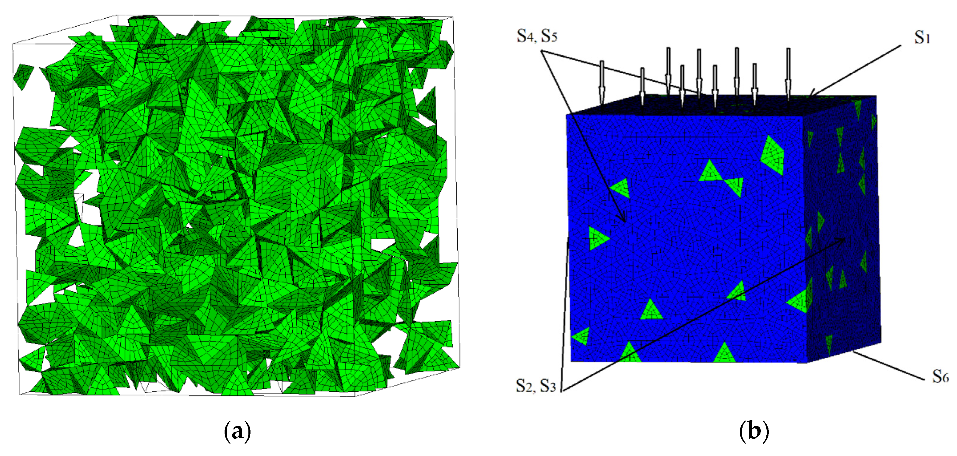
Figure 2.
Effective plastic strain rate in the ZrO2-15%Al2O3 composite upon compression in the shock front with an amplitude of 1200 m/s at successive intervals: (a) 25 ns; (b) 50 ns.
Figure 2.
Effective plastic strain rate in the ZrO2-15%Al2O3 composite upon compression in the shock front with an amplitude of 1200 m/s at successive intervals: (a) 25 ns; (b) 50 ns.
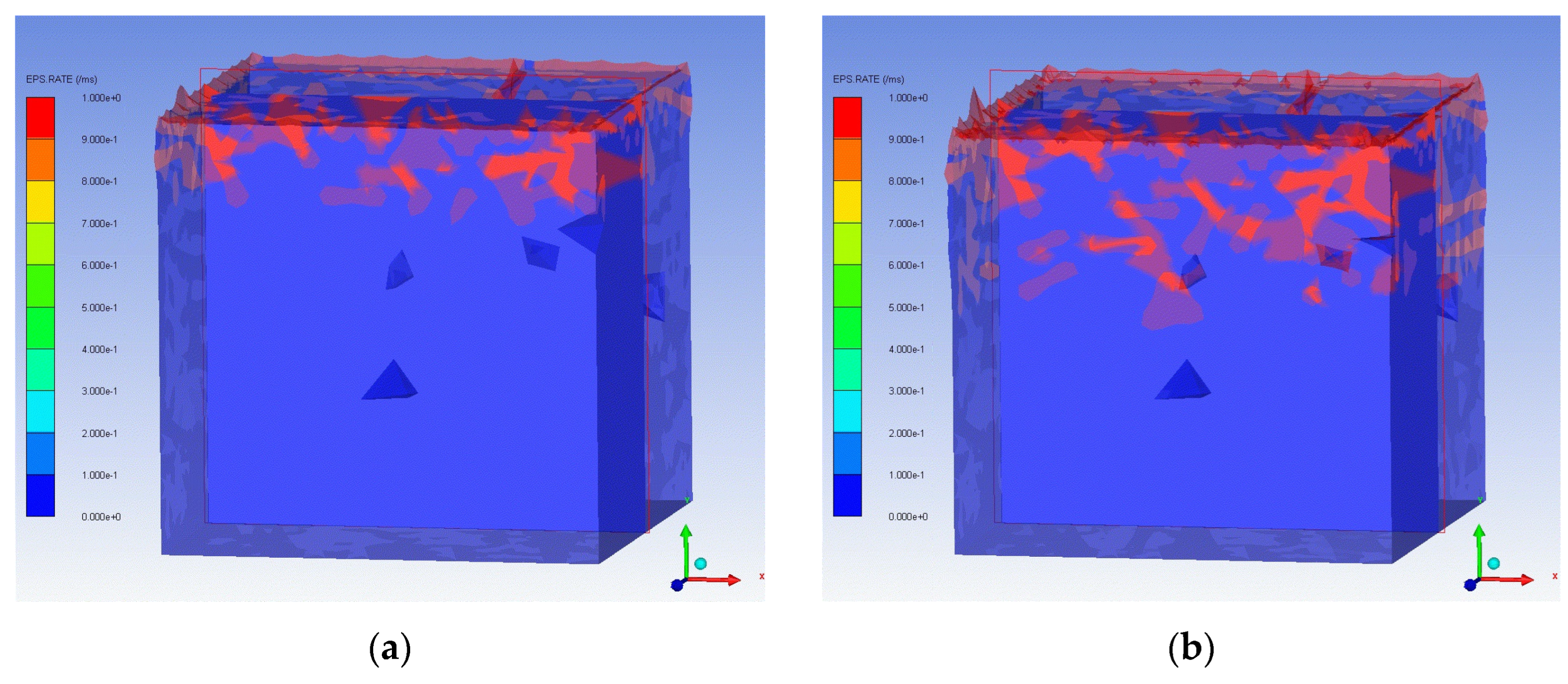
Figure 3.
Damage parameter (a) and specific destruction work (b) in the ZrO2-15%Al2O3 composite upon compression in the shock front with an amplitude of 1200 m/s.
Figure 3.
Damage parameter (a) and specific destruction work (b) in the ZrO2-15%Al2O3 composite upon compression in the shock front with an amplitude of 1200 m/s.
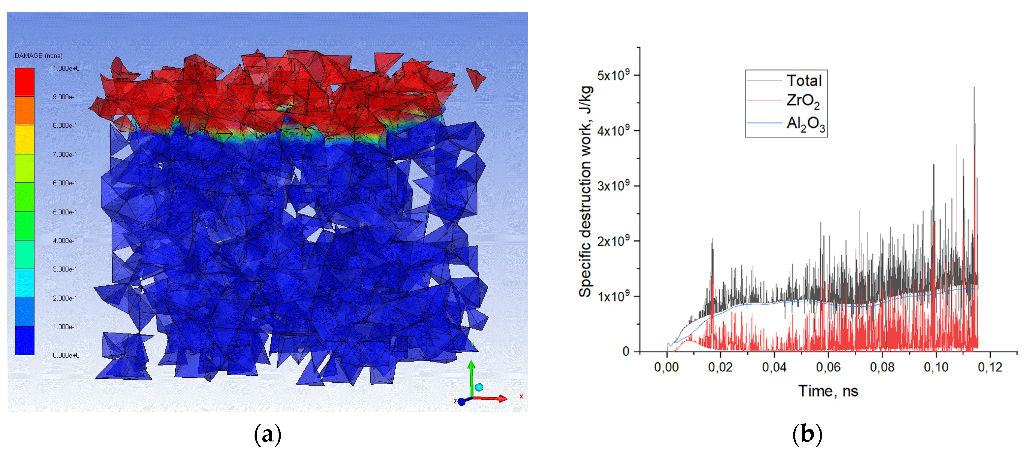
Figure 4.
Damage parameters in the model volume in the ZrO2-15%Al2O3 composite upon compression in the shock front with an amplitude of 1200 m/s at successive time intervals: (a) 25 ns; (b) 50 ns.
Figure 4.
Damage parameters in the model volume in the ZrO2-15%Al2O3 composite upon compression in the shock front with an amplitude of 1200 m/s at successive time intervals: (a) 25 ns; (b) 50 ns.
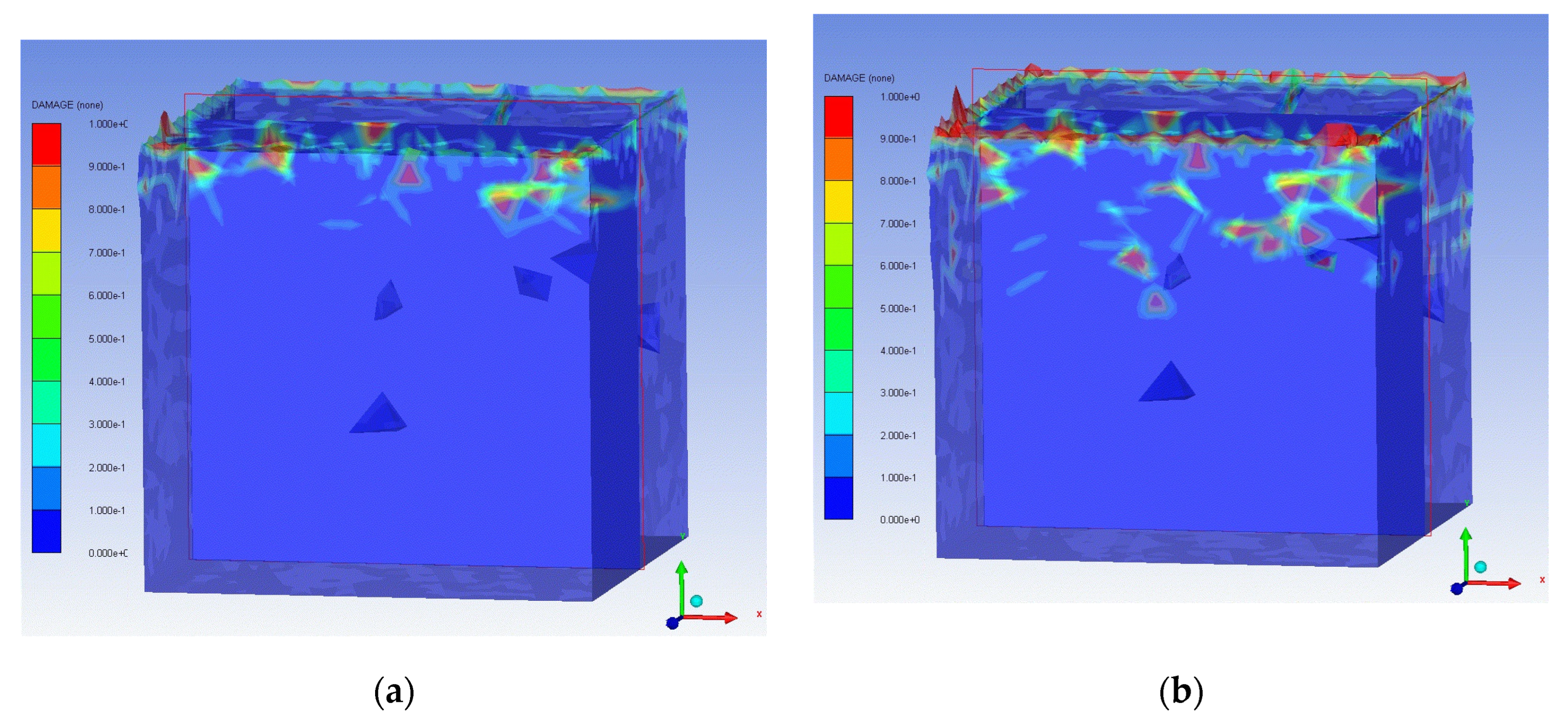
Figure 5.
Specific destruction work for ceramic composite phases for different loading speeds in the model volume in the ZrO2-5%Al2O3 composite: (a) Al2O3 phase; (b) ZrO2 phase.
Figure 5.
Specific destruction work for ceramic composite phases for different loading speeds in the model volume in the ZrO2-5%Al2O3 composite: (a) Al2O3 phase; (b) ZrO2 phase.
Figure 6.
Specific destruction work for ceramic composite phases for different loading speeds in the model volume in the ZrO2-10%Al2O3 composite: (a) Al2O3 phase; (b) ZrO2 phase.
Figure 6.
Specific destruction work for ceramic composite phases for different loading speeds in the model volume in the ZrO2-10%Al2O3 composite: (a) Al2O3 phase; (b) ZrO2 phase.
Figure 7.
Specific destruction work for ceramic composite phases for different loading speeds in the model volume in the ZrO2-15%Al2O3 composite: (a) Al2O3 phase; (b) ZrO2 phase.
Figure 7.
Specific destruction work for ceramic composite phases for different loading speeds in the model volume in the ZrO2-15%Al2O3 composite: (a) Al2O3 phase; (b) ZrO2 phase.

Table 1.
Elastic modulus and coefficients of equations of state for low-temperature crystalline phases.
Table 1.
Elastic modulus and coefficients of equations of state for low-temperature crystalline phases.
| Phase | α-Al2O3 | t-ZrO2 |
|---|---|---|
| Density ρ0, kg/m3 | 3890 | 6050 |
| Tm, K | 2327 | 2950 |
| Bulk modulus K1 (D0), GPa | 130.95 | 235 |
| K2, GPa | 0 | 0 |
| K3, GPa | 0 | 0 |
| B1 | 4.19 | 5.2 |
| Shear modulus µ, GPa | 90.16 | 76 |
| Gruneisen coefficient γ | 1 | 1 |
Table 2.
The coefficients of the model of the damaged medium for low-temperature crystalline phases.
Table 2.
The coefficients of the model of the damaged medium for low-temperature crystalline phases.
| Phase | α-Al2O3 | t-ZrO2 |
|---|---|---|
| Stress σHEL, GPa | 9.95 | 8.9 |
| Pressure PHEL, GPa | 14.6 | 5.66 |
| σS, GPa | 1.37 | 4.86 |
| A1, GPa | 0.93 | 0.9 |
| B2, GPa | 0.31 | 0.8 |
| C1 | 0.001 | 0 |
| C2 | 0.002 | 0 |
| m1 | 0.6 | 0.5 |
| m2 | 0.6 | 0.6 |
| D1 | 0.005 | 0.01 |
| D2 | 1 | 0.7 |
Disclaimer/Publisher’s Note: The statements, opinions and data contained in all publications are solely those of the individual author(s) and contributor(s) and not of MDPI and/or the editor(s). MDPI and/or the editor(s) disclaim responsibility for any injury to people or property resulting from any ideas, methods, instructions or products referred to in the content. |
© 2023 by the authors. Licensee MDPI, Basel, Switzerland. This article is an open access article distributed under the terms and conditions of the Creative Commons Attribution (CC BY) license (http://creativecommons.org/licenses/by/4.0/).
Copyright: This open access article is published under a Creative Commons CC BY 4.0 license, which permit the free download, distribution, and reuse, provided that the author and preprint are cited in any reuse.


