
Submitted:
11 December 2025
Posted:
12 December 2025
You are already at the latest version
Abstract
Additive manufacturing is one of the most efficient approaches for fabricating components with complex geometries. Among the wide variety of additive manufacturing technologies, extrusion-based processes using gel materials are attracting increasing attention from researchers. In this work, we consider the extrusion of gel materials for 3D printing and propose a method for calibrating additive manufacturing equipment based on optimization of the pre-extrusion and retraction parameters. Experimental studies were carried out on the extrusion of materials with different rheological properties. The capabilities of the proposed calibration method to improve printing quality are demonstrated using gel materials based on partially crosslinked sodium alginate with a viscosity of 1053 Pa·s. A multi-material 3D printing process was also implemented, enabling the combination of different materials within a single fabrication process. To realize the proposed 3D printing approach, we present a custom-built setup that allows the use of two extrusion modules for materials with different physicochemical properties. The capabilities of the developed system are demonstrated by fabricating a structure with an internal hollow channel and a structure based on a sodium alginate–chitosan polyelectrolyte complex.
Keywords:
extrusion-based 3D printing
; direct ink writing (DIW)
; hydrogel inks
; multi-material 3D printing
; hydrogel–thermoplastic hybrid scaffolds
; tissue engineering
; printability and dosing accuracy
; process parameters
1. Introduction
The implementation of modern technologies and equipment is a key factor in increasing the efficiency of manufacturing processes, improving product quality, and reducing costs. One of the most promising directions in this context is the use of additive manufacturing technologies, or 3D-printing processes [1]. Additive manufacturing encompasses processes based on the layer-by-layer fabrication of parts by depositing material onto a build platform. 3D printing makes it possible to obtain objects with complex geometries and internal architectures that are difficult or impossible to produce using traditional manufacturing methods such as casting or machining [2].
The most widespread additive manufacturing technologies are those based on extrusion processes [3]. In this case, the formation of a solid structure can occur via various physicochemical transformations such as crystallization, photopolymerization, chemical crosslinking, removal of a volatile solvent, etc. [4,5,6]. At present, two main extrusion-based 3D-printing technologies are distinguished: fused deposition modeling (FDM) and direct ink writing (DIW) [7].
FDM is used to fabricate parts from thermoplastic polymers—high-molecular-weight compounds that soften upon heating and transition to a viscous-flow state, while recovering their initial characteristics upon cooling [8]. In turn, when fabricating parts from thermolabile materials, viscous gels, or dispersed systems, direct ink writing is employed [9,10]. The key distinction of this approach is the absence of any need to heat the polymer prior to its deposition onto the build platform. In DIW, the geometry of the final part is formed due to the specific rheological properties of the used materials, namely shear-thinning behavior, thixotropy, and the presence of a yield stress [11,12,13].
In recent years, extrusion-based additive manufacturing has attracted growing attention from researchers for the fabrication of parts with functional properties by combining several materials within a single technological process. One way to achieve this is to employ two independent extruder modules that process materials with different physicochemical characteristics within one printing run [17]. The multi-material 3D-printing process is based on the sequential deposition of materials, which allows the part to be divided into functional zones with tailored properties. This approach significantly broadens the application area of the fabricated parts by improving their biological performance, electrical conductivity, and mechanical characteristics [18].
For example, in [19] scaffolds for tissue engineering applications were obtained using viscous inks based on sodium alginate in combination with a thermoplastic polymer, polycaprolactone, which was employed to enhance the mechanical properties of the final construct. In addition, the material formulations for multi-extrusion 3D printing can be selected such that a chemical reaction occurs between them, which can be used to fix the structure and eliminate the need for additional post-processing steps [20].
A key factor determining the quality of printed parts is precise control over material dosing during 3D printing. However, the extrusion of viscous gel materials through small-diameter nozzles is associated with technological challenges caused by the inertia of the feeding mechanism and the viscoelastic behavior of the materials [21,22]. These phenomena and processes may lead to insufficient material extrusion during part formation, resulting in thinning and breakage of deposited filaments, as well as spontaneous oozing of the material after extrusion is stopped. To improve print quality, various approaches are used to select process parameters, including methods based on machine learning [23], mathematical modeling [24,25], and the implementation of additional control loops [26]. Of particular interest are calibration methods based on the sequential variation of the system control parameters. Their use makes it possible to avoid complex analytical studies, since the required operating mode of the equipment is determined experimentally by comparing the actual and target dosed mass, which greatly simplifies process setup.
In this work, we present equipment for implementing additive manufacturing processes, namely a multi-extrusion 3D-printing process using thermoplastics and biopolymer-based gel materials. In addition, we propose a calibration procedure for the gel extruder based on optimizing the pre-extrusion and retraction length parameters. To assess the applicability of the proposed calibration method and the technical capabilities of the developed setup, a 3D-printing study was carried out in which complex-shaped parts were fabricated, namely: (1) a part with an internal hollow channel based on sodium alginate and the thermoplastic polymer polycaprolactone; and (2) a part based on a polyelectrolyte complex formed by sequential extrusion of sodium alginate– and chitosan-based gel materials..
2. Results and Discussion
The fabrication of parts using multi-material 3D-printing technology is a process of sequentially building the geometry by depositing layers of materials with different compositions. The 3D-printing process involving gel-based materials can be represented in the form of a block diagram that describes the sequence of the required operations (Figure 1).
The 3D-printing process begins with the design of a digital model with complex geometry using computer-aided design (CAD) systems. Next, depending on the required macro- and mesoporous structure of the final part, suitable materials are selected for the printing process. At the following stage, the process parameters are defined, namely the printing head travel speed, the nozzle orifice diameter, and the layer height. These parameters are specified by the user and depend on the desired properties of the final product. It should be noted that the flow rate of the gel materials during extrusion, which is governed by the rheological properties of the material and the process conditions, has a significant influence on the printing process. Based on the selected process parameters, a sequence of G-code commands is generated and sent to the 3D printer control board, after which the part fabrication process is carried out.
2.1. Calibration Process of Extrusion Gel-Like Materials
Stepwise extrusion experiments (Section 4.4) were carried out for partly crosslinked alginate based on 2 wt% sodium alginate with added CaCl₂, as well as for a reference sample of pure water. The experiment consisted of 7 extrusion cycles, each delivering 0.3 g of material at a constant plunger speed of 0.0035 mm/s, with a 5 s pause between cycles. This setup makes it possible to assess the accumulation of mass deviation when using gel materials with different rheological properties (Figure 2).
The largest deviation from the theoretical curve is observed for the material with the addition of 0.2 wt% calcium chloride (Figure 2c). The shape of the obtained curves and the magnitude of their deviation from the theoretical dependence reflect the differences in the rheological properties of the materials (Figure 3).
An increase in calcium chloride concentration markedly raises the solution viscosity due to the formation of a stable polymer gel network. In addition, the flow behavior of the “ink” changes, and an increase in the degree of shear-thinning is observed, which is reflected in the slope of the flow curves. However, establishing a direct quantitative relationship between the rheological parameters of the material and the magnitude of the extrusion deviation is a complex analytical task, owing to the multitude of concurrent processes during extrusion—local pressure losses, viscosity reduction of the ink followed by relaxation, and the inertia of the feeding mechanism. To ensure accurate dosing of gel materials, an algorithm for extruder calibration was proposed.
Based on the preliminary studies, the printing parameters were optimized for the gel formulation exhibiting the highest degree of shear-thinning behavior, namely 2 wt% sodium alginate and 0.2 wt% CaCl₂. The determination of the additional displacement length EPr/R was carried out with a step ΔEPr/R of 0.001 mm and a required accuracy ε of 0.01. For the selected formulation, experimental curves of the deposited mass as a function of time were obtained. In addition, to assess the applicability of the proposed approach, a direct ink writing process was performed to fabricate a lattice structure with dimensions of 10 × 10 × 0.5 mm and a spacing of 1.2 mm between adjacent filaments at different displacement values EPr/R (Figure 4).
When analyzing the performance of the algorithm and varying the controlled parameter, the experimental values approached the prescribed mass setpoints, and the target accuracy was achieved at a displacement value of 0.115 mm. In this case, the mass deviation, calculated as the average over all extrusion cycles, was 0.006 g.
The printed samples, in turn, demonstrate that pre-extrusion and retraction have a pronounced effect on part formation and make it possible to improve the quality of 3D printing. At EPr/R = 0 (Figure 4a), virtually no continuous extrusion was observed, and only isolated segments of material were deposited on the build platform, which did not form an integral lattice. When the displacement was increased to EPr/R = 0.051 mm (Figure 4b), the extrusion process became more stable; however, gaps between the filaments remained in the resulting structure, indicating an insufficient volume of extruded gel material. At EPr/R = 0.115 mm (Figure4c), the lattice structure was formed uniformly, with well-defined filaments of uniform thickness and an adequate material supply throughout the entire process. These results indicate that the proposed solution can significantly improve the quality of the printed parts and stabilize the extrusion of gel materials during 3D printing process.
3.2. Multimaterial 3D Printing Process
The proposed extrusion calibration approach was used for the experimental investigation of the formation of complex-shaped parts by multi-material extrusion-based 3D printing. Within this study, two fundamentally different part configurations were fabricated:
Parts with internal hollow channels formed using gel materials based on partially crosslinked sodium alginate, with a supporting framework made of a thermoplastic polymer.
Parts based on a polyelectrolyte complex (PEC) of the sodium alginate–chitosan system, obtained by sequential extrusion of the corresponding polymer solutions.
3.1.1. Object with Hollow Channels
In the implementation of the multi-material 3D-printing process aimed at fabricating a part with an internal hollow channel, extrusion modules for both the thermoplastic polymer and the gel materials were employed. Partially crosslinked sodium alginate was used as the primary material of the construct. It should be noted that, despite its suitable rheological properties, the formation of channels using only the gel material is not feasible. To prevent channel collapse during the fabrication of overhanging structures, the thermoplastic polymer polycaprolactone was used to form the channel walls. The proposed three-dimensional part geometry was imported into dedicated slicing software (Ultimaker Cura) to generate the corresponding set of control commands for the 3D printer (Figure 5).
Regardless of the physicochemical properties of the materials, the printing process was carried out at a printing speed of 10 mm/s and a layer height of 0.4 mm. To form the main framework of the part based on partially crosslinked sodium alginate, the plunger speed of the gel extruder was set to 0.035 mm/s, with a nozzle orifice diameter of 0.41 mm and a calibration value EPr/R of 0.115. The walls of the hollow channel made of polycaprolactone were printed at an extruder temperature of 80 °C and a nozzle diameter of 0.4 mm.
The formation of a stable three-dimensional structure after printing was completed by inducing gelation of sodium alginate in a 1 wt% calcium chloride crosslinking solution for 1 hour (Figure 6).
To remove the rigid polycaprolactone framework forming the channel walls, it is dissolved by repeated washing with the solvent dichloromethane.
3.2.2. Object Based on a Polyelectrolyte Complex
In the fabrication of the part based on a polyelectrolyte complex, two gel-extrusion modules were used. The stability of the construct during printing is ensured by the formation of a hybrid structure due to the chemical reaction between the polyanion sodium alginate and the polycation chitosan, resulting in the corresponding polyelectrolyte complex.
For the printing process, a geometry with characteristic dimensions of 20 × 20 × 5 mm (L × W × H) was designed in a computer-aided design system. The printing procedure involved the sequential deposition of sodium alginate and chitosan layers with equal layer thickness (Figure 7).
Experimental studies of the printing process were carried out under the following conditions: layer height 0.4 mm, nozzle orifice diameter 1.67 mm, and printing speed 10 mm/s. The pre-extrusion and retraction length EPr/R, determined in accordance with the proposed calibration procedure, was 0.085 for sodium alginate and 0.009 for chitosan.
Upon completion of the printing process, a stable construct was obtained that required no additional post-processing, which indicates that the formation of the polyelectrolyte complex had been completed (Figure 8).
To generate a porous structure, the obtained part can be subjected to supercritical or freeze-drying processes, including the necessary preparatory steps.
3. Conclusions
Additive manufacturing is a versatile tool for solving a wide range of problems, including in medicine, pharmaceutics, and chemical engineering. A promising and relevant direction is the use of additive manufacturing technologies for the design and development of new materials with tailored functional properties, which can significantly broaden their application areas. The present study investigates multi-material 3D printing processes aimed at creating composite or hybrid structures using materials with different physicochemical properties within a single technological process. To implement this approach, an additive manufacturing setup was designed and constructed. It provides a large build volume for the fabrication of final parts and allows processing both thermoplastic materials (with melting temperatures up to 280 °C) and viscous inks of various compositions with viscosities up to 2500 Pa·s.
To determine the flow rate of gel materials during the printing process, a calibration method was developed. The applicability of the proposed method was demonstrated in experimental studies and in the optimization of printing parameters for parts fabricated using gel materials based on partially crosslinked sodium alginate. The developed approach was subsequently employed for the implementation of multi-material 3D printing.
Using the setup architecture and extruder calibration method presented in this work, a multi-material 3D printing process was implemented. The possibility of fabricating a part with an internal hollow channel based on partially crosslinked sodium alginate and a thermoplastic polymer (polycaprolactone) is demonstrated. In addition, to illustrate the possibility of combining viscous inks within a single process, the fabrication of parts based on a polyelectrolyte complex is demonstrated. The resulting complex-shaped parts can be subjected to supercritical or freeze-drying to form a highly porous internal structure, which may promote cell proliferation and growth.
4. Materials and Methods
4.1. Materials
Sodium alginate (CAS Number: 9005-38-3, Sigma-Aldrich, St. Louis, MO, USA) and acid-soluble chitosan with a molecular weight of 111 kDa (Sigma-Aldrich, St. Louis, MO, USA) were used as precursors for the gel materials. The fused deposition process was carried out using a commercially available thermoplastic polycaprolactone (eSUN, China) supplied as a filament. Other materials, including distilled water and calcium chloride, were purchased from RusChem (Moscow, Russia)..
4.2. Method of Ink Preparation and Rheology Measurement
Gel materials based on partially crosslinked sodium alginate for extrusion experiments and 3D-printing were prepared using a rotor–stator homogenizer (T 25 digital ULTRA TURRAX, IKA, Germany). A predetermined amount of calcium chloride was dissolved in water to obtain a concentration of 0.2 wt% and stirred until the salt was completely dissolved. Sodium alginate was then added to the resulting solution to reach a concentration of 2 wt%, while mixing at 13,000 rpm for 7 min.
For the multi-material printing experiments, sodium alginate solution with a concentration of 4 wt% (viscosity 5.7 Pa·s) and chitosan solution with a concentration of 2 wt% (viscosity 0.2 Pa·s) were selected. The chitosan-based formulation was prepared by dissolving 2 wt% chitosan in 0.1 M acetic acid. Similarly, the 4 wt% sodium alginate solution was obtained by dissolving sodium alginate in distilled water.
Before starting the 3D-printing process, air bubbles formed during gel preparation were removed from all materials using a centrifuge (C 2201 S-20-15, ELMI, Latvia) operated at 2500 rpm for 5 min.
The viscosity of the polymer solutions used was measured with a rotational rheometer (SmartPave 102e, Anton Paar, Switzerland) equipped with a cone–plate geometry (diameter 50 mm), at a constant temperature of 20 °C and a shear rate of 0.1 s⁻¹.
4.3. Installation for 3D Printing Process
In this study, a custom-built setup was used to implement the multi-material 3D-printing process (Figure 9).
The multi-material 3D-printing setup provides a build volume of 300 × 300 × 350 mm (L × W × H). A distinctive feature of the design is its modular mounting system, which enables rapid reconfiguration of the 3D printer to address different manufacturing tasks. To achieve this, a carriage design was proposed, on which the extruders are mounted using a slot-type connection (Figure 10).
The required module is installed on the moving carriage (Figure 10a) using a specially designed slot connection (1). For the positioning mechanism, the carriage is attached to the rail guide (2) and the trapezoidal nut (3) by bolted joints. In addition, a matching counterpart of the slot connection was designed (Figure 10b), which is subsequently used in the extruder modules.
4.3.1. Description of Extruder for Thermoplastic Polymer
For 3D printing with thermoplastic polymers, a filament-fed extruder was used due to its simple design and the broad commercial availability of filament materials (Figure 11).
Initially, the material (1) in the form of a filament enters the feeding mechanism (2) and gradually moves along the extruder until it reaches the heating block (4). In this zone, the polymer melts and is delivered onto the build platform through the nozzle (5). Heating is provided by an integrated cartridge heater and a thermistor-based temperature sensor. In addition, the design is equipped with a heat sink (4) to remove excess heat outside the heating zone. In the presented configuration, material feeding is achieved by the rotation of gears that grip the filament between them (Figure 12).
During material loading, the polymer filament (2) is clamped between the pressure roller (5) and the idler gear (4) using the adjustment screw (3). Feeding of the polymer filament occurs when the drive gear (6), which is mounted on the stepper motor (1), rotates. The assembly is enclosed in a housing; after the main components are installed, the cover (7) is mounted.
3.3.2. Description of Extruder for Gel-Like Materials
For the direct ink writing process, a piston-driven extruder configuration was developed (Figure 13).
In the upper part of the module housing (2), mounting holes are provided for attaching the stepper motor (1) using four M3×25 bolts. To transmit torque from the stepper motor to the trapezoidal screw (5), a belt drive with a 1:3 ratio (3) is used, consisting of two pulleys with diameters of 12 and 36 mm, respectively. The rotational motion is then transferred to the lead screw (5), which drives the plunger element (4). As it moves downward along the linear guides (6), material is dispensed from the reservoir (8), which is fixed to the module housing (2) by a dedicated holder (7).
The plunger element is a composite assembly consisting of two parts: a carriage and an adapter for a 10 mL syringe (Figure 14).
The carriage of the plunger assembly is a composite structure consisting of two parts fastened together with thirteen M3×18 screws (Figure 14a). The internal space of the assembly is designed to accommodate two M8 nuts (1), which provide motion of the carriage along the Z-axis, as well as two rolling bearings (2) for the linear guides. To secure the reservoir for the gel materials, a dedicated syringe adapter was designed, which is mounted on the carriage (Figure 14b). Owing to the absence of threaded connections, the proposed design enables rapid replacement of the material and allows syringes of different volumes to be used for loading.
4.4. Method of Extrusion Calibration
Calibration of the equipment for direct ink writing is carried out on the basis of experimental studies of the extrusion process. During calibration, a stepwise material feed is considered, in which extrusion occurs periodically. This method is close to real printing conditions: each step corresponds to the deposition of an individual filament and makes it possible to quantitatively assess how the mass of extruded material changes under repeated on/off switching of the feed. The dosing accuracy is evaluated by comparing the actual mass of the deposited material with the prescribed theoretical value.
The extruder with the mounted syringe was fixed above an analytical balance (Ohaus PR 200, Ohaus, New Jersey, USA). A beaker filled with water was placed on the balance, and the extruder nozzle was partially immersed in the water to reduce surface tension forces acting on the gel materials during extrusion.
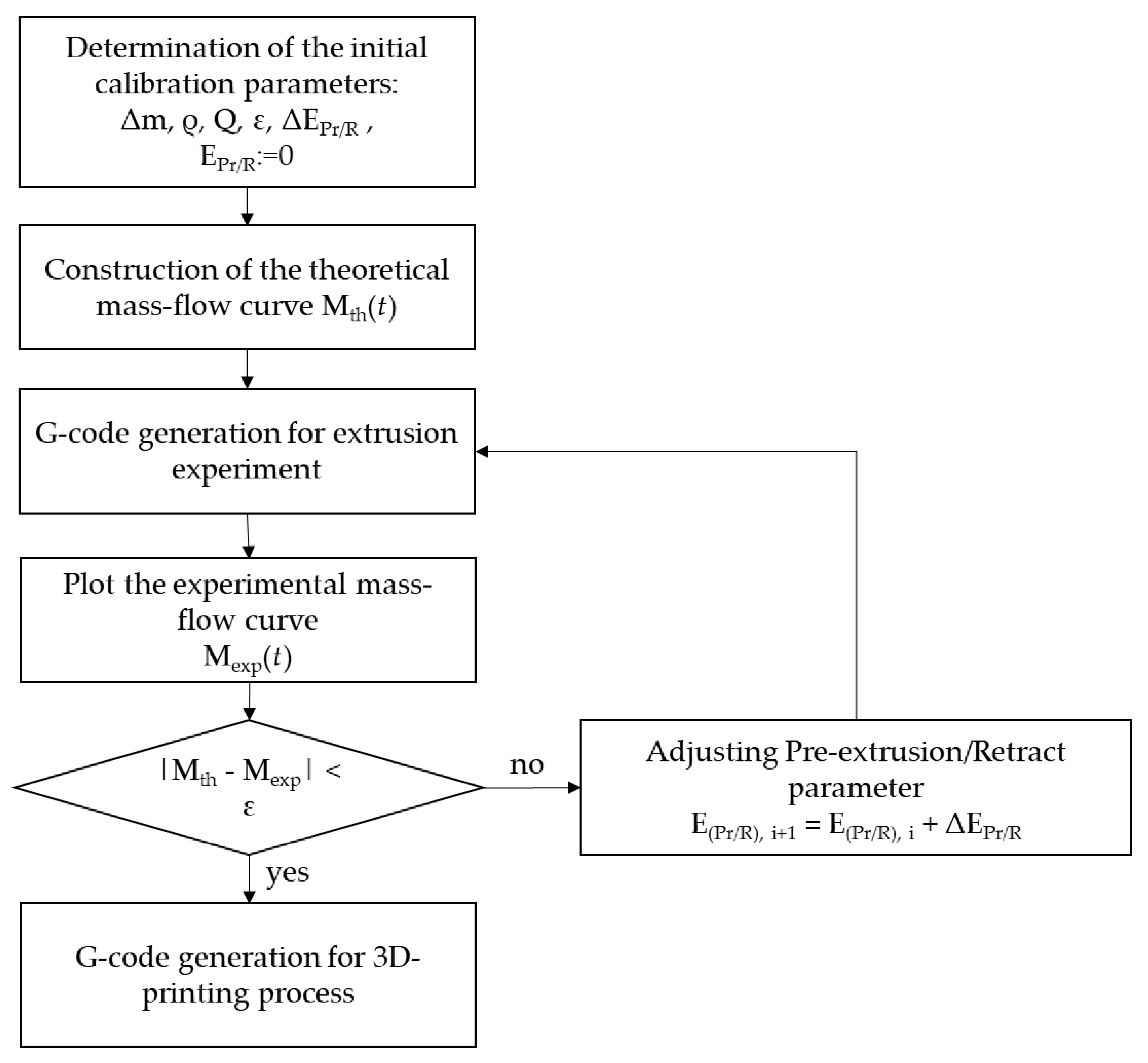
To compensate for the discrepancy between the experimental and theoretical extrusion curves, an algorithm was developed to optimize the flow rate of gel materials as a function of their rheological properties. This algorithm is based on introducing an additional piston displacement parameter, EPr/R, during pre-extrusion and retraction, defined as the distance travelled by the piston (in mm). Pre-extrusion is understood as preliminary material extrusion required to reduce the viscosity of the material before the start of printing. Retraction is the reverse piston motion aimed at reducing the pressure inside the extruder and preventing material oozing after the end of extrusion. The optimal values of the displacement parameter were determined according to the developed procedure (Figure 15).
The algorithm is implemented using an iterative approach. At each step, a control program is generated with a specified value of the EPr/R parameter. Based on the experimental results, the deviation between the theoretically calculated and experimentally measured material mass is evaluated, after which the value of EPr/R is adjusted until the desired dosing accuracy is achieved. A detailed description of the algorithm steps is given below.
In the first step, the input data required for the optimization algorithm are defined. The target mass Δm of the material with density ρ is specified, which is to be dosed at a given flow rate Q. The allowable error ε is set, defining the maximum permissible deviation between the theoretical and experimentally measured mass. In addition, the step parameters of the algorithm are assigned: the increment ΔEPr/R, which determines the change in the displacement value between successive iterations, as well as the initial value used as the first approximation. In this way, a set of initial parameters is formed that define the starting conditions and the accuracy of the algorithm.
At the next stage, the theoretical dependence of the dispensed material mass on time, Mth(t), is calculated for the selected material and printing parameters. The theoretical curve can be expressed as follows (Equitation (1)):
where t0 is the start time of extrusion and t1 is the end time of extrusion.
The resulting theoretical curve Mth(t) escribes the amount of material that should be extruded at each moment in time. This curve is used as a reference for subsequent comparison with the experimental data.
sing the parameters defined above and the theoretical model, a set of G-code control commands is generated for the extrusion of the gel materials. During execution of the program, the experimental dependence of the extruded material mass on time Mexp(t) is recorded. The theoretical curve Mth(t) is then compared with the experimental dependence Mexp(t). As the optimality criterion, the absolute mass deviation |Mth(t)− Mexp(t)| is used, which is evaluated at the end of each extrusion cycle.
If the condition |Mth(t)− Mexp(t)|< ε is not satisfied, the algorithm proceeds to the stage of adjusting the displacement parameter. The value of EPr/R is updated according to the following expression:
The updated value of EPr/R is then substituted into the G-code generation block, a new set of control commands is formed, and the experiment is repeated. If the calculated deviation does not exceed the specified tolerance ε, the selected value of EPr/R is considered to provide sufficient dosing accuracy for the material under study. In this case, the algorithm terminates the iterative process, and the obtained value of the coordinate is taken as optimal and is subsequently used for the 3D-printing process.
Author Contributions
Conceptualization, A.A. and N.M.; methodology, A.A. and Y.S; software, Y.S.; validation, Y.S., A.A.; investigation, Y.S.; writing—original draft preparation, A.A., Y.S. and N.M; writing—review and editing, N.M.; supervision, N.M.; project administration, A.A. All authors have read and agreed to the published version of the manuscript.
Funding
The research was funded by the Russian Science Foundation No. 23-13-00368.
Conflicts of Interest
The authors declare no conflict of interest. The funders had no role in the design of the study; in the collection, analyses, or interpretation of data; in the writing of the manuscript; or in the decision to publish the results.
References
- Abramov, A.A.; Men’shutina, N.V. Additive Technologies for Medicine, Pharmacy, and Chemical Industry: Applications and Outlook. Theoretical Foundations of Chemical Engineering 2023, 57, 532–544. [Google Scholar] [CrossRef]
- Iftekar, S.F.; Aabid, A.; Amir, A.; Baig, M. Advancements and Limitations in 3D Printing Materials and Technologies: A Critical Review. Polymers 2023, 15, 2519. [Google Scholar] [CrossRef] [PubMed]
- Generalova, A.N.; Demina, P.A.; Akasov, R.A.; Khaydukov, E.V. Photopolymerization in 3D printing of tissue-engineered constructs for regenerative medicine. Russian Chemical Reviews 2023, 92, RCR5068. [Google Scholar] [CrossRef]
- Vatani, M.; Choi, J.-W. Direct-print photopolymerization for 3D printing. Rapid Prototyping Journal 2017, 23, 337–343. [Google Scholar] [CrossRef]
- Davila, J.L.; d’Avila, M.A. Rheological Evaluation of Laponite/alginate Inks for 3D Extrusion-based Printing. Int J Adv Manuf Technol 2019, 101, 675–685. [Google Scholar] [CrossRef]
- Ouyang, L.; Yao, R.; Zhao, Y.; Sun, W. Effect of Bioink Properties on Printability and Cell Viability for 3D Bioplotting of Embryonic Stem Cells. Biofabrication 2016, 8, 035020. [Google Scholar] [CrossRef]
- Wickramasinghe, S.; Do, T.; Tran, P. FDM-Based 3D Printing of Polymer and Associated Composite: A Review on Mechanical Properties, Defects and Treatments. Polymers 2020, 12, 1529. [Google Scholar] [CrossRef]
- Saadi, M.A.S.R.; Maguire, A.; Pottackal, N.T.; Hoque, Md.T.H.; Thakur; Ikram, M, Md; Hart, J.H.; Ajayan, P.M.; Rahman, M.M. Direct Ink Writing: A 3D Printing Technology for Diverse Materials 2022. Advanced Materials 34, 2108855. [CrossRef]
- Baniasadi, H.; Abidnejad, R.; Fazeli, M.; Lipponen, J.; Niskanen, J.; Kontturi, E.; Seppälä, J.; Rojas, O.J. Innovations in hydrogel-based manufacturing: A comprehensive review of direct ink writing technique for biomedical applications. Advances in Colloid and Interface Science 2024, 324, 103095. [Google Scholar] [CrossRef]
- Leonov, D.V.; Spirina, Yu.A.; Yacenko, A.A.; Kushnarev, V.A.; Barannikov, S.V. Perspektivnye tehnologii 3D-biopechati. Citologiya 2021, 63, 309–321. [Google Scholar] [CrossRef]
- Rau, D.A.; Williams, C.B.; Bortner, M.J. Rheology and Printability: A Survey of Critical Relationships for Direct Ink Write Materials Design. Progress in Materials Science 2023, 140, 101188. [Google Scholar] [CrossRef]
- Amorim, P.A.; d’Avila, M.A.; Anand, R.; Moldenaers, P.; Puyvelde, P.Van; Bloemen, V. Insights on Shear Rheology of Inks for Extrusion-Based 3D Bioprinting. Bioprinting 2021, 22, e00129. [Google Scholar] [CrossRef]
- Herrada-Manchon, H.; Fernández, A.; Aguilar, E. Essential Guide to Hydrogel Rheology in Extrusion 3D: How to Measure It and Why It Matters? Bioprinting. Gels 2023, 9, 517. [Google Scholar] [CrossRef]
- GhavamiNejad, A.; Ashammakhi, N.; Wu, X.Y.; Khademhosseini, A. Crosslinking Strategies for 3D Bioprinting of Polymeric Hydrogels. Small 2020, 16, e2002931. [Google Scholar] [CrossRef]
- Palma, J.H.; Bertuola, M.; Hermida, E.B. Modeling calcium diffusion and crosslinking dynamics in a thermogelling Alginate-Gelatin-Hyaluronic acid ink: 3D bioprinting applications. Bioprinting 2024, 24, e00224. [Google Scholar] [CrossRef]
- Zennifer, A.; Manivannan, S.; Sethuraman, S.; Kumbar, S.G.; Sundaramuthi, D. 3D bioprinting and photocrosslinking: emerging strategies & future perspectives. Biomaterials 2022, 134, 112576. [Google Scholar] [CrossRef]
- Brown, N.C.; Ames, D.C.; Mueller, J. Multimaterial extrusion 3D printing printheads. Nature Reviews Materials 2025, 10, 807–825. [Google Scholar] [CrossRef]
- Rafiee, M.; Farahani, R.D.; Therriault, D. Multi-Material 3D and 4D Printing: A Survey. Advanced Science 2020, 7, 1902307. [Google Scholar] [CrossRef]
- Schuurman, W.; Khristov, V.; Pot, M.W.; van Weeren, P.R.; Dhert, W.J.A.; Malda, J. Bioprinting of hybrid tissue constructs with tailorable mechanical properties. Biofabrication 2011, 3, 021001. [Google Scholar] [CrossRef]
- Yuxuan, L.; Shengnan, C.; Huilong, W.; Xiao, L.; Deng, Z.; Huang, J.; Zhang, Z. Coaxial 3D printing of hierarchical structured hydrogel scaffolds for on-demand repair of spinal cord injury. Acta Biomaterialia 2023, 168, 400–415. [Google Scholar] [CrossRef] [PubMed]
- Ozbolat, I.T.; Hospodiuk, M. Current advances and future perspectives in extrusion-based bioprinting. Biomaterials 2016, 76, 321–343. [Google Scholar] [CrossRef] [PubMed]
- Estelle, K.T.; Gozen, B.A. Complex ink flow mechanisms in micro-direct-ink-writing and their implications on flow rate control. Additive Manufacturing 2022, 59, 103183. [Google Scholar] [CrossRef]
- Perera, Y.S.; Li, J.; Abeykoon, C. Machine learning enhanced grey box soft sensor for melt viscosity prediction in polymer extrusion processes. Scientific Reports 2025, 15. 5613. [Google Scholar] [CrossRef]
- Lorenz, J.; Hildner, M.; van den Bogert, W.; Zhu, B.; Yee, S.; Fazeli, N.; Shih, A.J. Modeling of the high-viscosity fluid transient flow for material deposition in direct ink writing. Additive Manufacturing 2025, 109, 104836. [Google Scholar] [CrossRef]
- Yongqiang, T.; Hassan, A.; Siadat, A.; Yang, G. Analytical modeling of deposited filaments for high viscosity material-based piston-driven direct ink writing. The International Journal of Advanced Manufacturing Technology 2022, 123, 3387–3398. [Google Scholar] [CrossRef]
- Estelle, K.T.; Gozen, B.A. Complex ink flow mechanisms in micro-direct-ink-writing and their implications on flow rate control. Additive Manufacturing 2022, 59, 103183. [Google Scholar] [CrossRef]
Figure 1.
Block diagram of the manufacturing process for parts using gel-based materials and 3D printing.
Figure 1.
Block diagram of the manufacturing process for parts using gel-based materials and 3D printing.
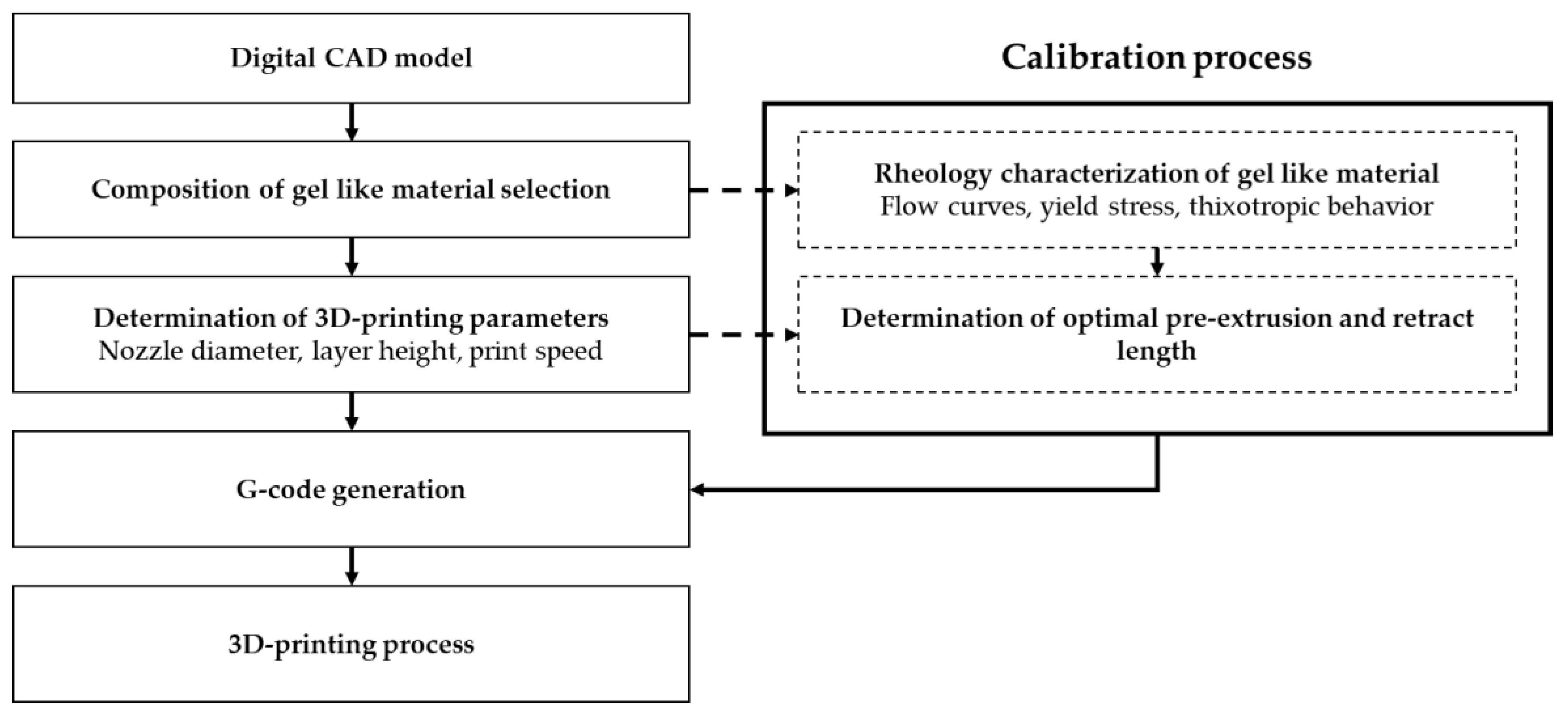
Figure 2.
Experimental and theoretical extrusion curves for pure water (a), partially crosslinked sodium alginate with a concentration of 0.05 wt% (b), and partially crosslinked sodium alginate with a concentration of 0.20 wt%.
Figure 2.
Experimental and theoretical extrusion curves for pure water (a), partially crosslinked sodium alginate with a concentration of 0.05 wt% (b), and partially crosslinked sodium alginate with a concentration of 0.20 wt%.
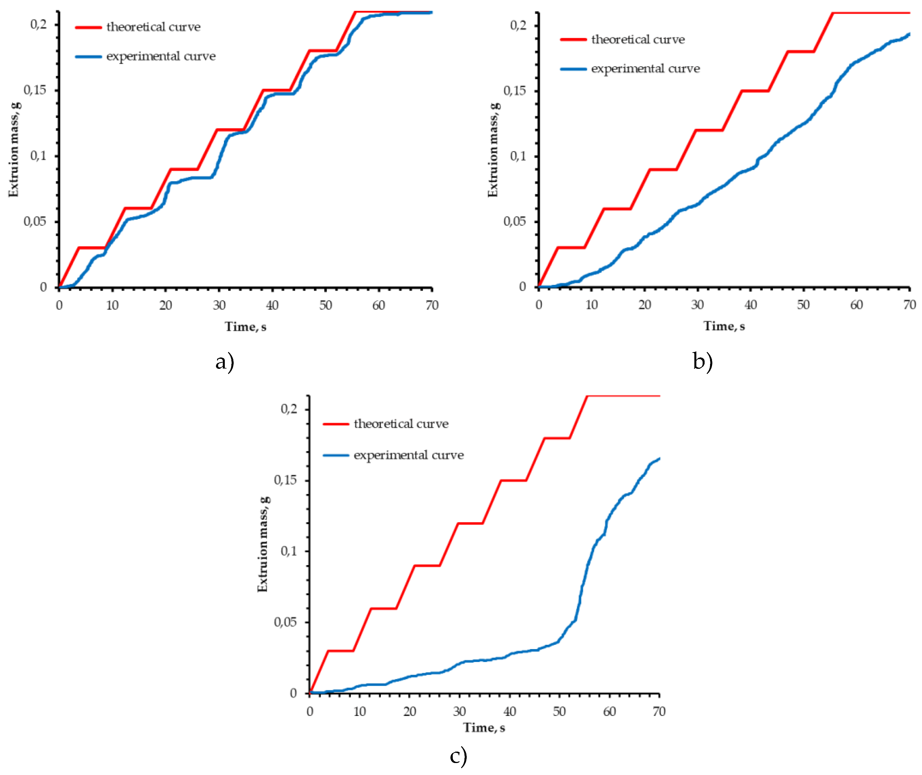
Figure 3.
Viscosity (a) and flow (b) curves of the materials used.
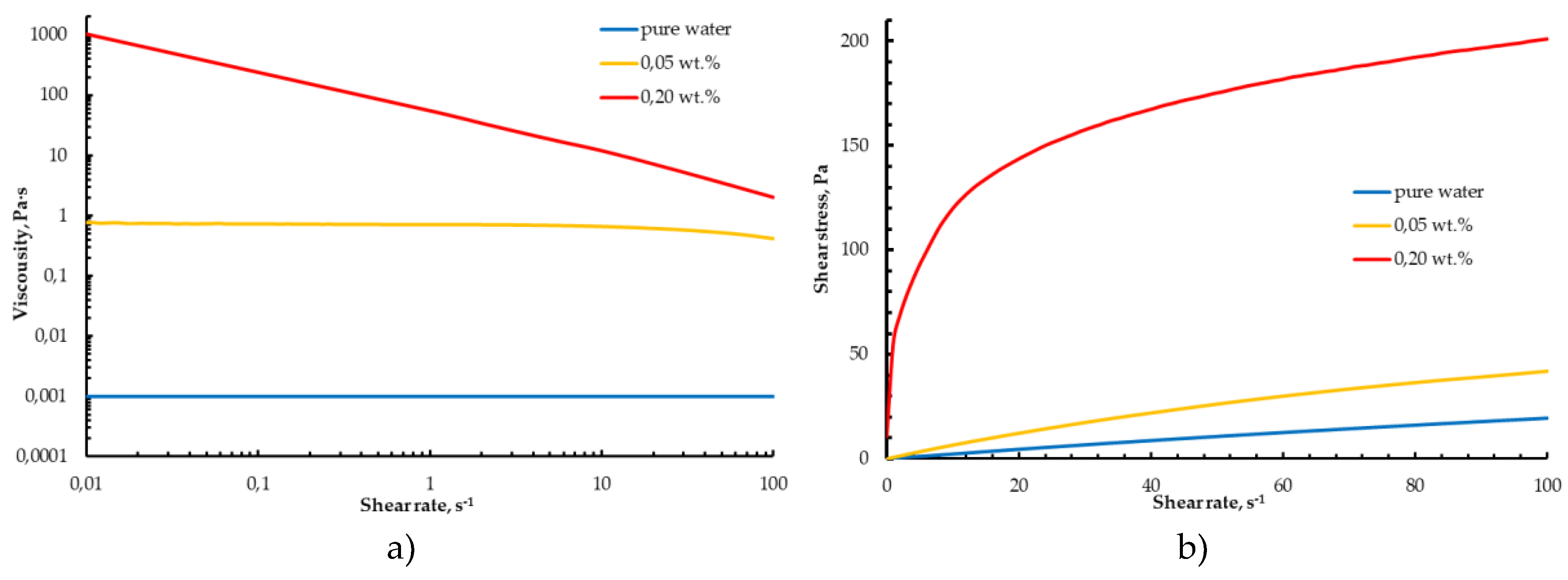
Figure 4.
Figure 4. Influence of the offset parameter EPr/R (mm) on the extrusion of gel materials\\ and the corresponding 3D-printed structures: (a) EPr/R = 0; (b) EPr/R = 0.051; (c) EPr/R = 0.115.
Figure 4.
Figure 4. Influence of the offset parameter EPr/R (mm) on the extrusion of gel materials\\ and the corresponding 3D-printed structures: (a) EPr/R = 0; (b) EPr/R = 0.051; (c) EPr/R = 0.115.
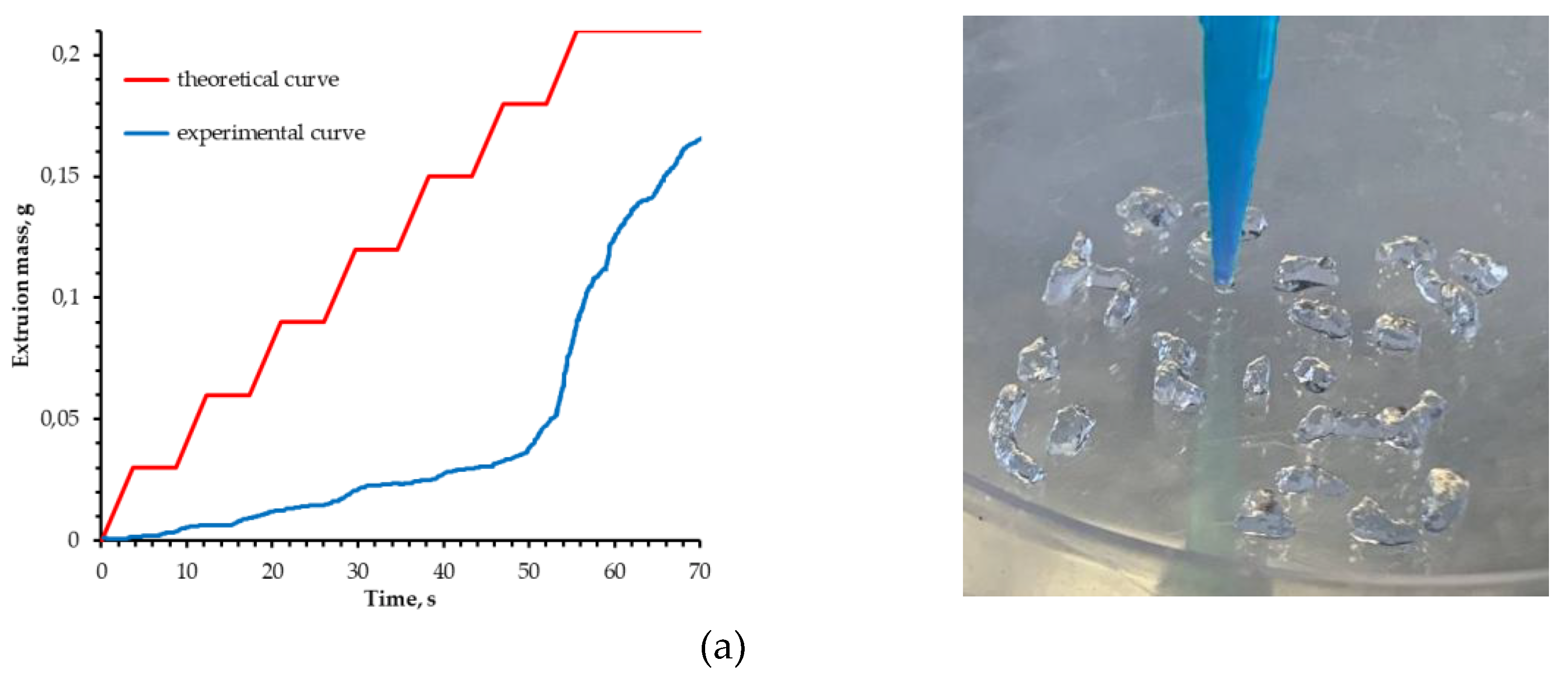
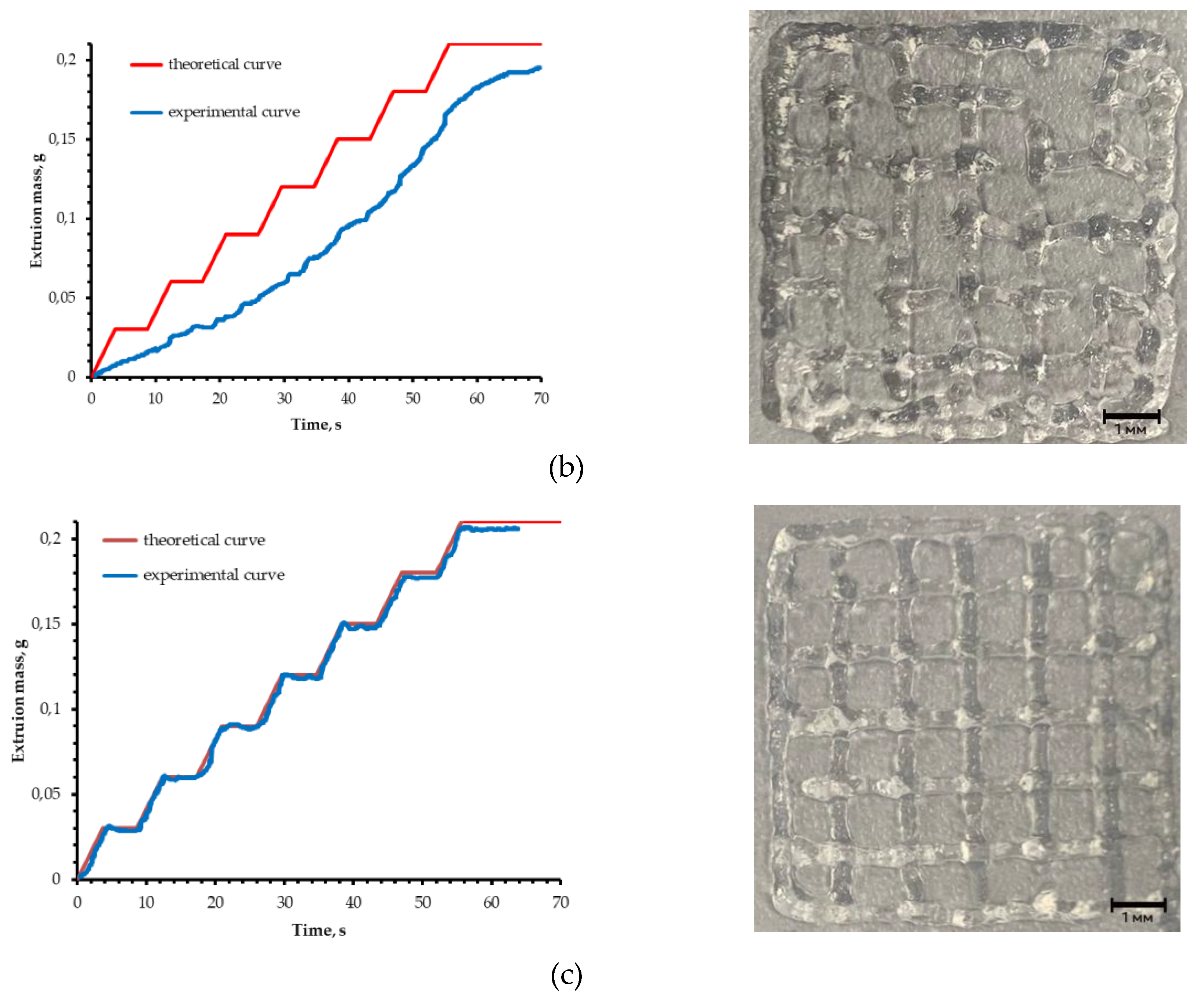
Figure 5.
Visualization of the layer structure used in the process (a) and the part geometry designed for the implementation of the multi-extrusion 3D-printing process (b).
Figure 5.
Visualization of the layer structure used in the process (a) and the part geometry designed for the implementation of the multi-extrusion 3D-printing process (b).
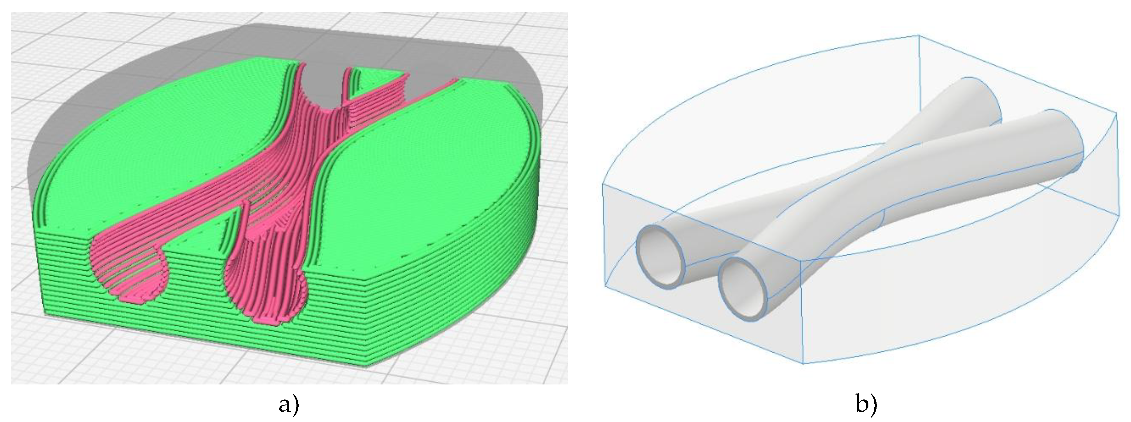
Figure 6.
Part based on partially crosslinked sodium alginate with an internal hollow channel after completion of the gelation process.
Figure 6.
Part based on partially crosslinked sodium alginate with an internal hollow channel after completion of the gelation process.
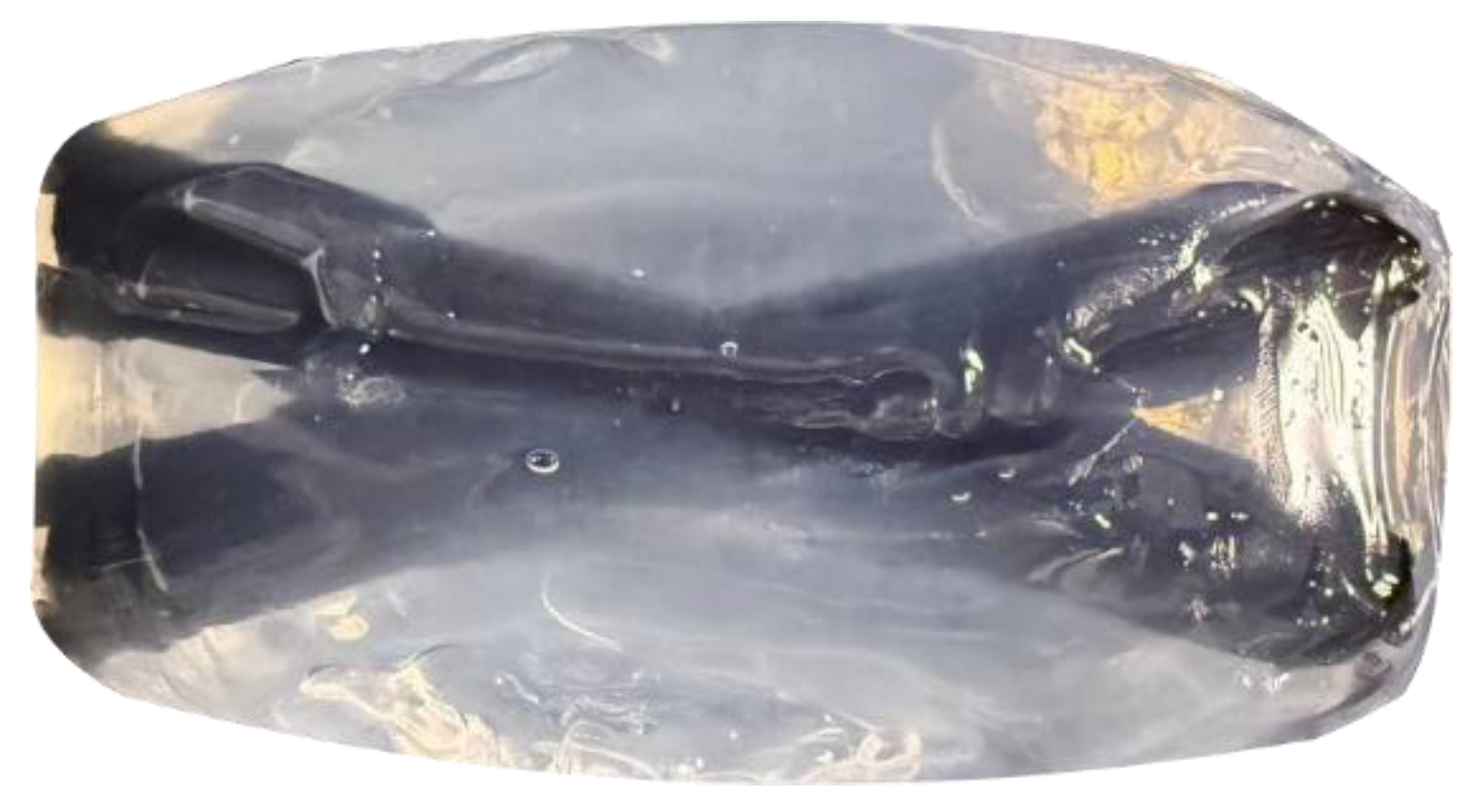
Figure 7.
Visualization of the material layers in the part based on a sodium alginate–chitosan polyelectrolyte complex.
Figure 7.
Visualization of the material layers in the part based on a sodium alginate–chitosan polyelectrolyte complex.
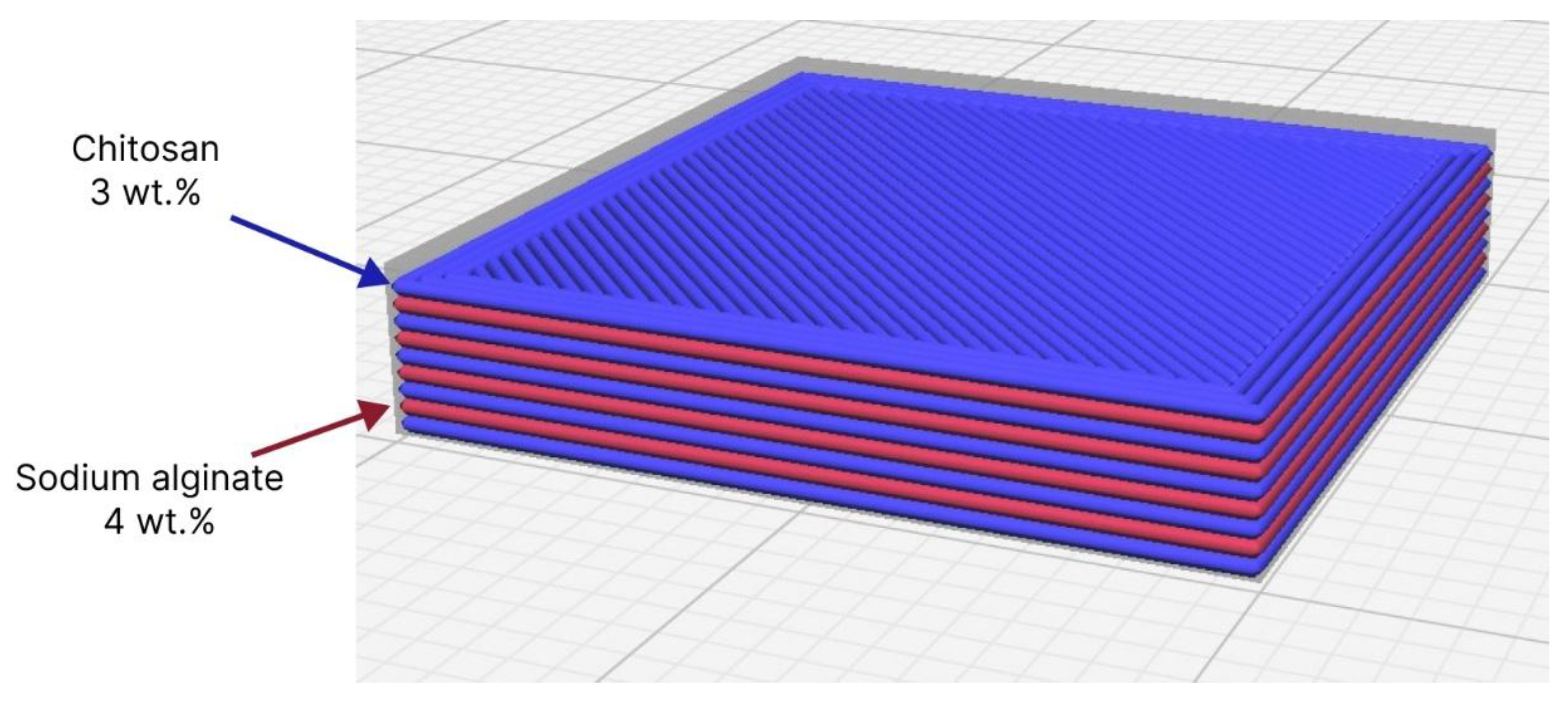
Figure 8.
Part based on the polyelectrolyte complex after completion of the 3D-printing process.
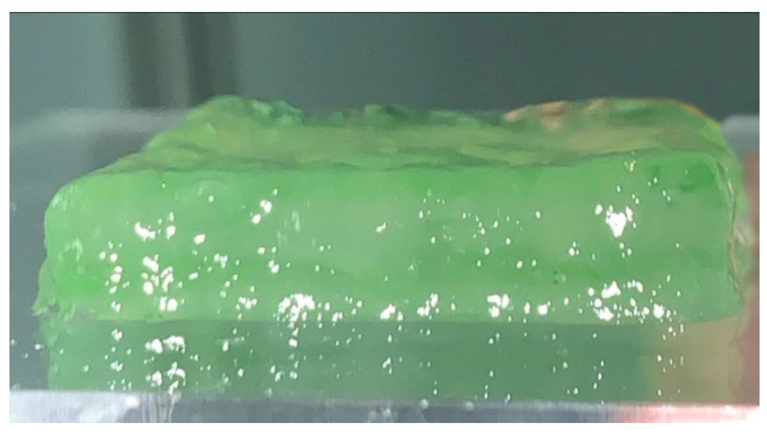
Figure 9.
Modular setup for implementing multi-material 3D printing.
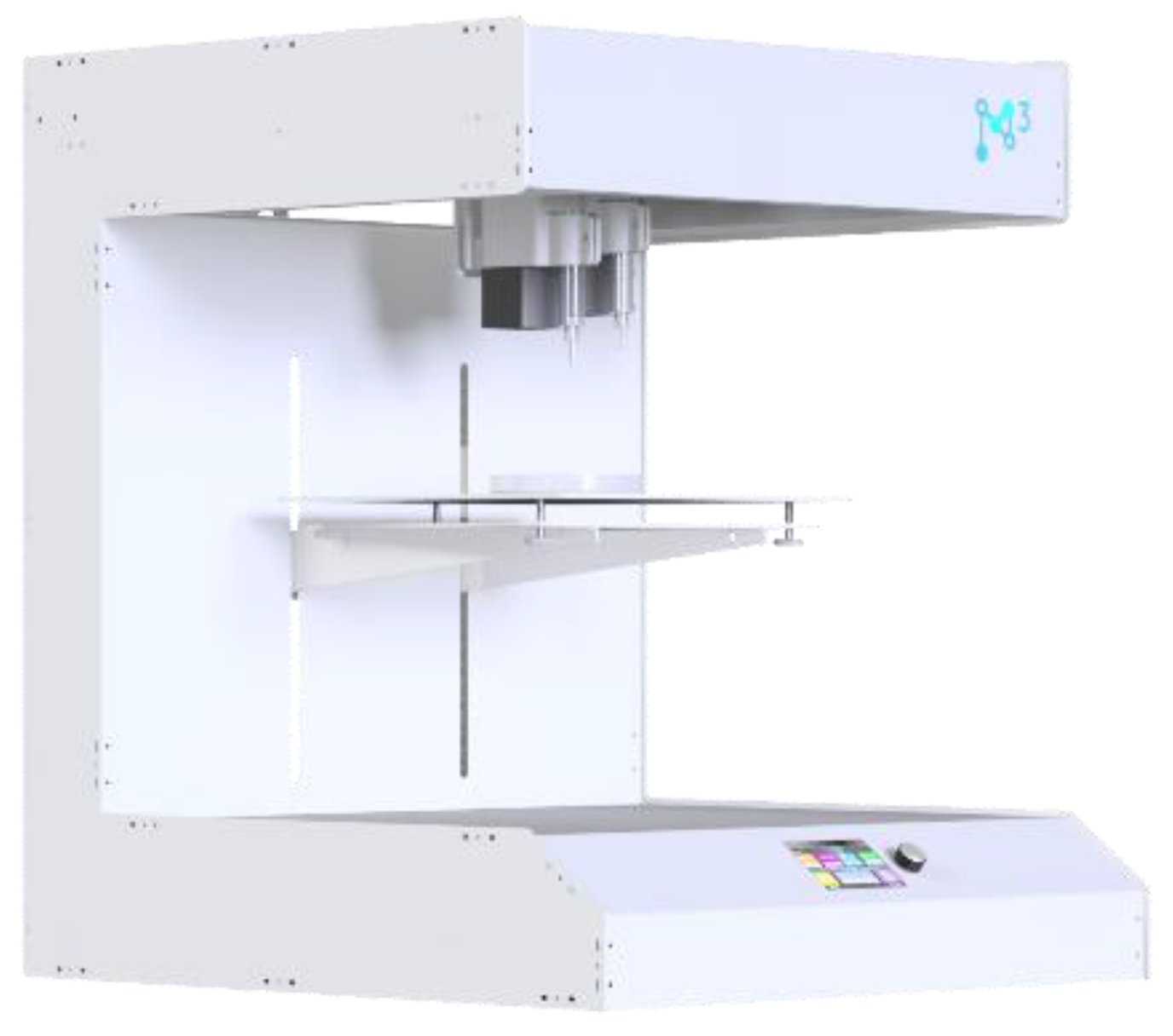
Figure 10.
Ensuring the modularity of the additive manufacturing equipment: (a) design of the 3D-printer carriage: 1 – slot for mounting the extruder; 2 – hole for the trapezoidal nut; 3 – holes for mounting on the linear guide; (b) mating slot component of the extruder module.
Figure 10.
Ensuring the modularity of the additive manufacturing equipment: (a) design of the 3D-printer carriage: 1 – slot for mounting the extruder; 2 – hole for the trapezoidal nut; 3 – holes for mounting on the linear guide; (b) mating slot component of the extruder module.
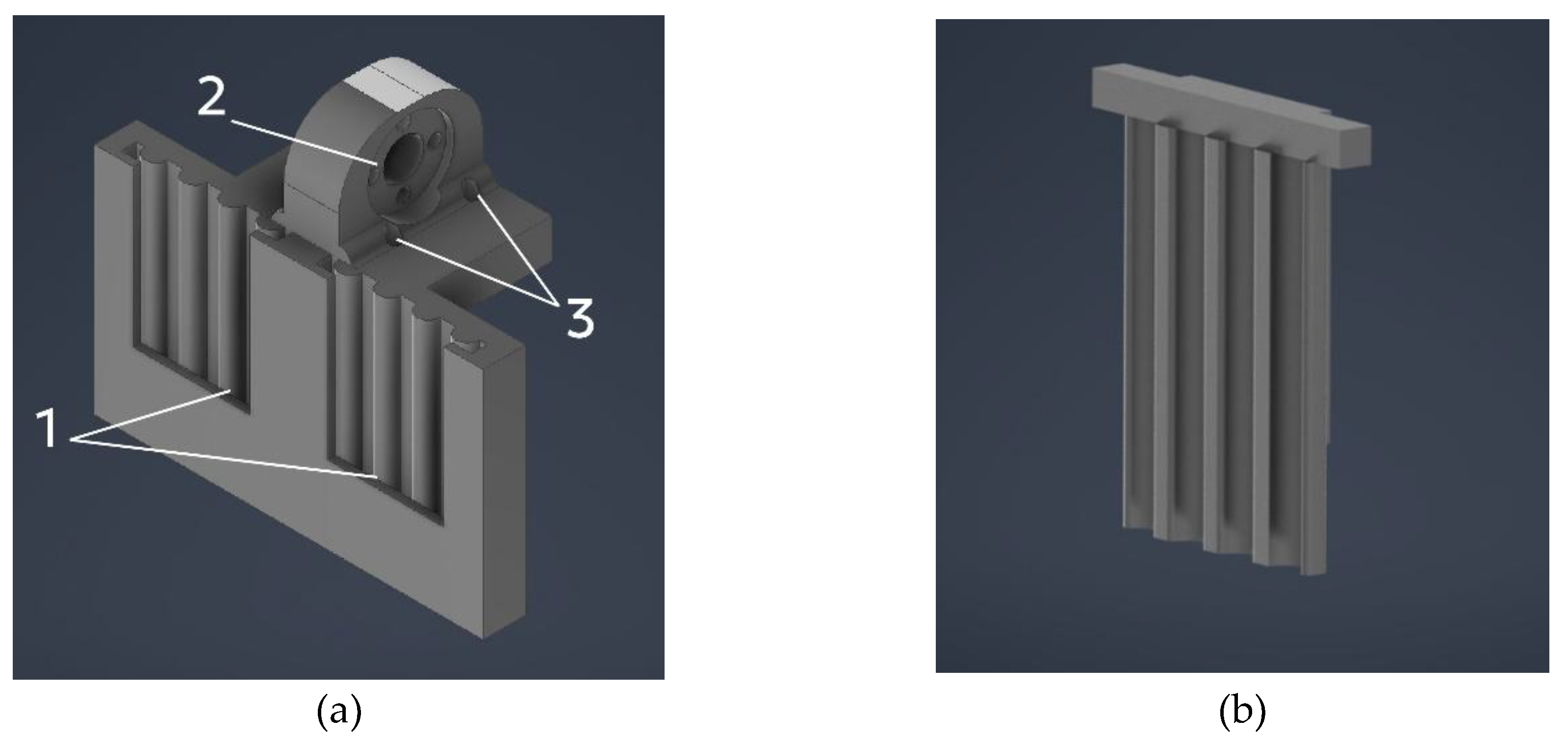
Figure 11.
Extruder for thermoplastic polymer: 1 – polymer filament; 2 – feeding mechanism; 3 – heat sink; 4 – heating block; 5 – nozzle.
Figure 11.
Extruder for thermoplastic polymer: 1 – polymer filament; 2 – feeding mechanism; 3 – heat sink; 4 – heating block; 5 – nozzle.
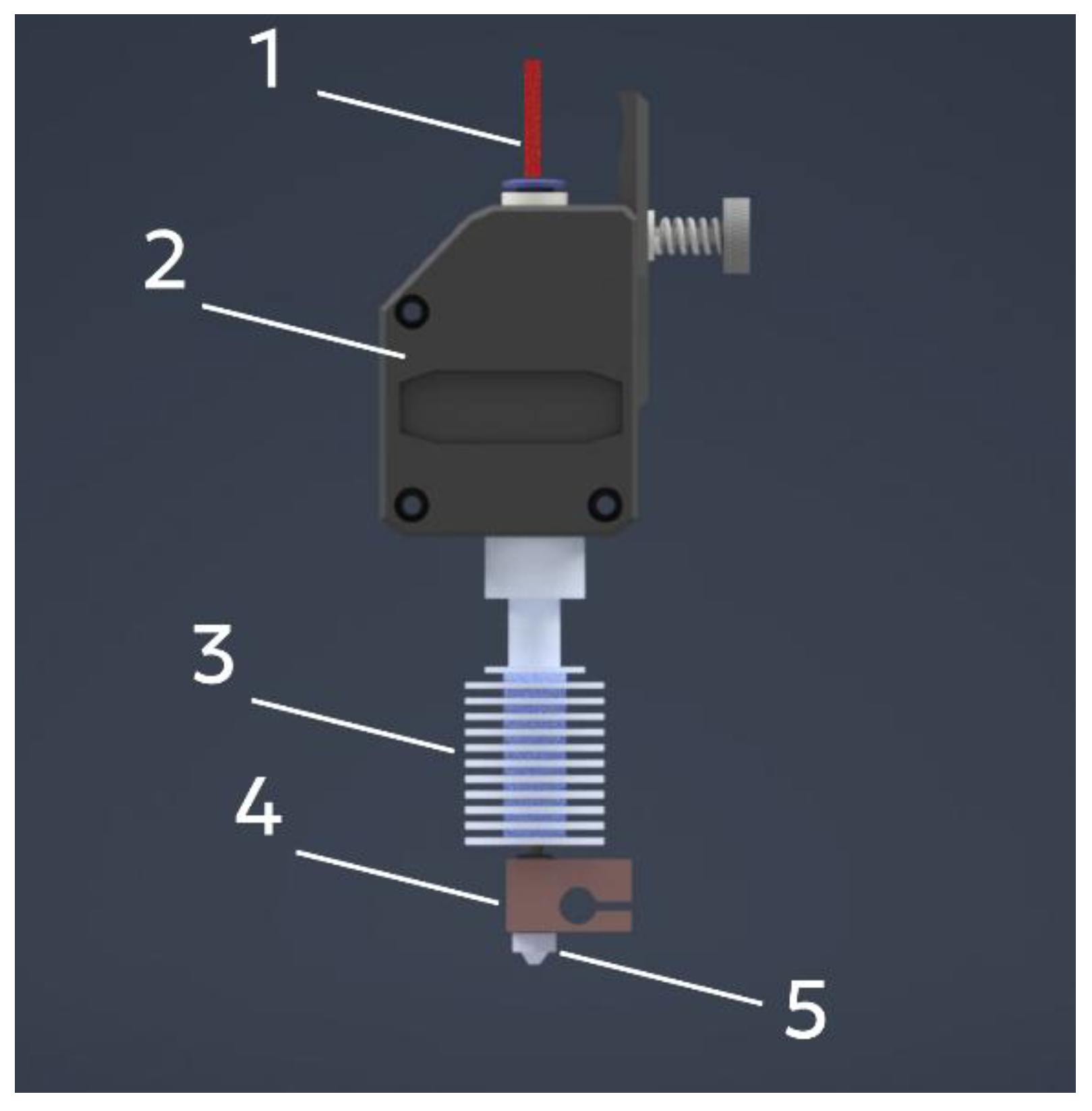
Figure 12.
Feeding mechanism in the thermoplastic polymer filament extruder: 1 – stepper motor; 2 – filament; 3 – adjustment screw; 4 – idler gear; 5 – pressure roller; 6 – drive gear; 7 – cover.
Figure 12.
Feeding mechanism in the thermoplastic polymer filament extruder: 1 – stepper motor; 2 – filament; 3 – adjustment screw; 4 – idler gear; 5 – pressure roller; 6 – drive gear; 7 – cover.
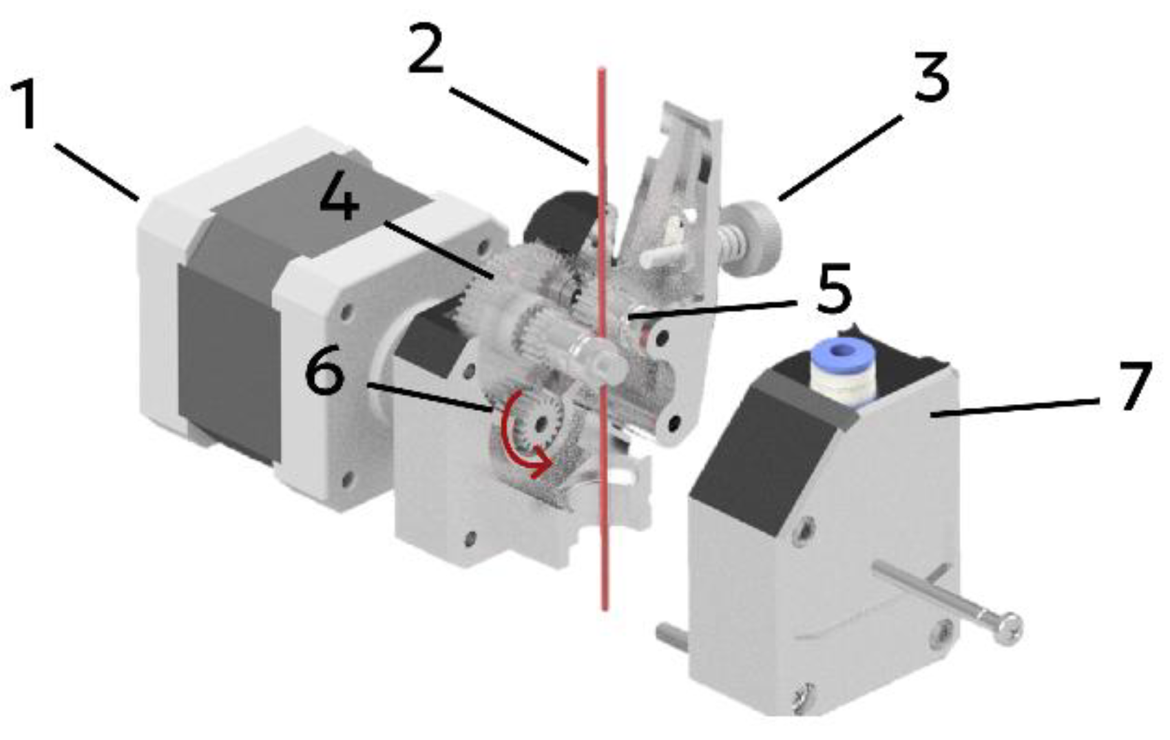
Figure 13.
Design of the extruder for 3D printing with gel materials: (1) stepper motor; (2) module housing; (3) belt drive; (4) plunger element; (5) lead screw; (6) linear guides; (7) holder for the material reservoir; (8) material reservoir.
Figure 13.
Design of the extruder for 3D printing with gel materials: (1) stepper motor; (2) module housing; (3) belt drive; (4) plunger element; (5) lead screw; (6) linear guides; (7) holder for the material reservoir; (8) material reservoir.
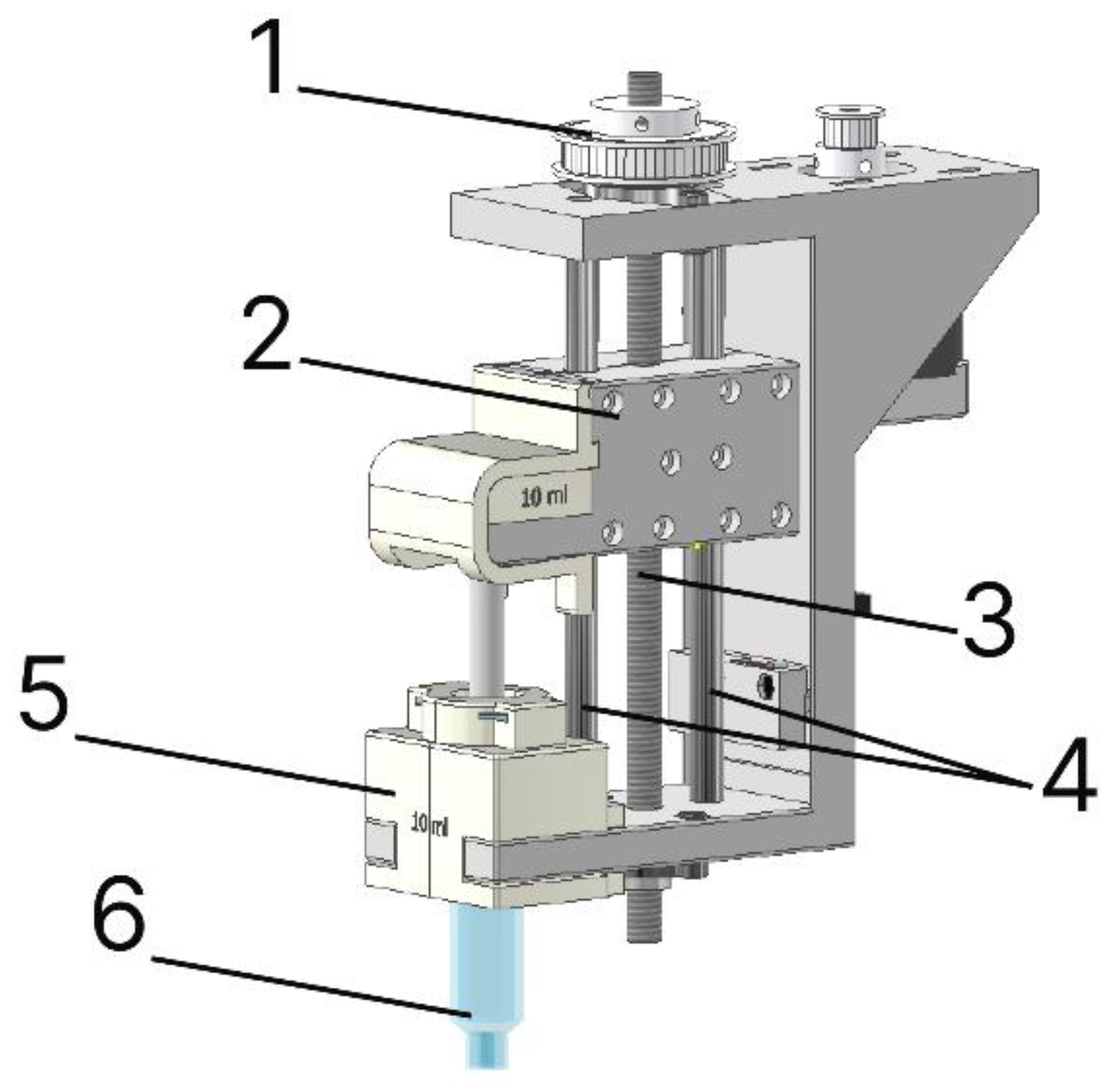
Figure 14.
Design of the plunger assembly: (a) carriage: 1 – nut; 2 – rolling bearing; (b) syringe adapter.
Figure 14.
Design of the plunger assembly: (a) carriage: 1 – nut; 2 – rolling bearing; (b) syringe adapter.
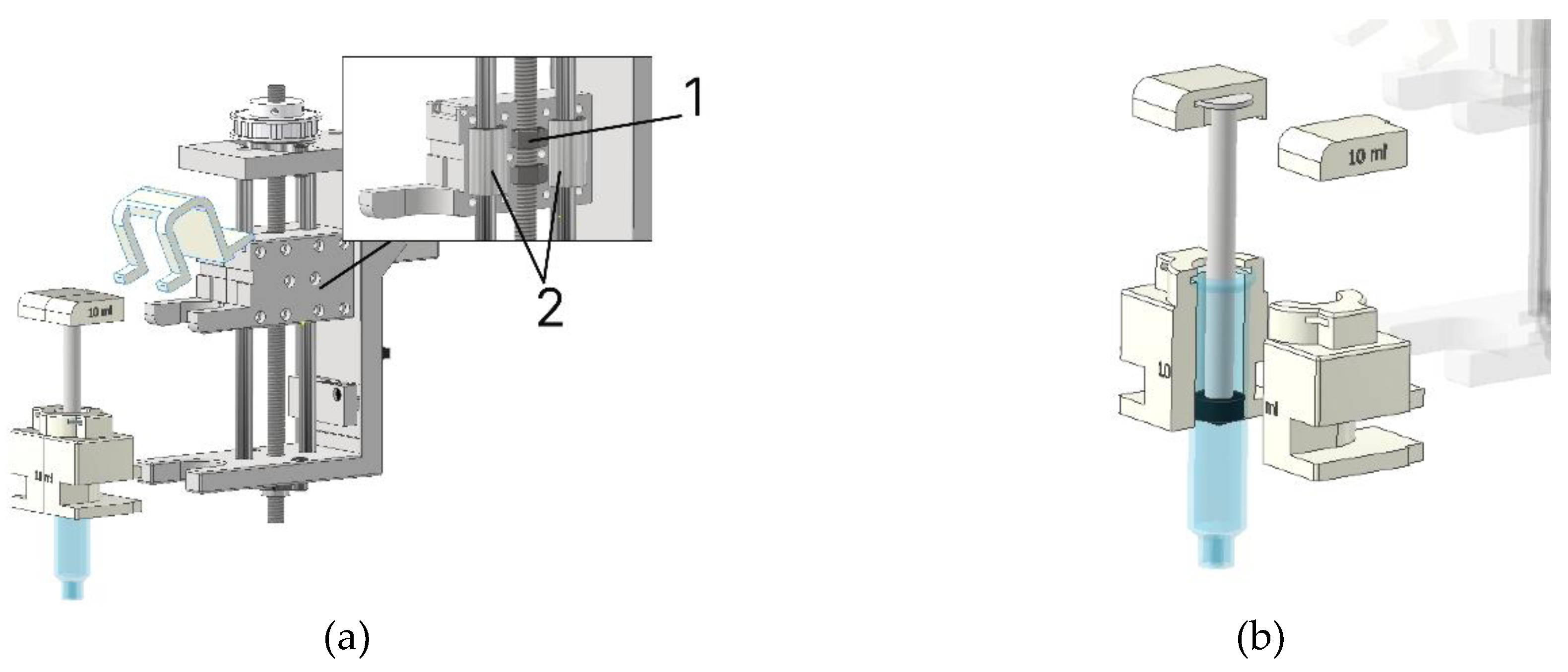
Figure 15.
Algorithm for calibrating additive manufacturing equipment for printing with gel materials.
Figure 15.
Algorithm for calibrating additive manufacturing equipment for printing with gel materials.
Disclaimer/Publisher’s Note: The statements, opinions and data contained in all publications are solely those of the individual author(s) and contributor(s) and not of MDPI and/or the editor(s). MDPI and/or the editor(s) disclaim responsibility for any injury to people or property resulting from any ideas, methods, instructions or products referred to in the content. |
© 2025 by the authors. Licensee MDPI, Basel, Switzerland. This article is an open access article distributed under the terms and conditions of the Creative Commons Attribution (CC BY) license (http://creativecommons.org/licenses/by/4.0/).
Copyright: This open access article is published under a Creative Commons CC BY 4.0 license, which permit the free download, distribution, and reuse, provided that the author and preprint are cited in any reuse.


