Submitted:
11 December 2025
Posted:
12 December 2025
You are already at the latest version
Abstract
Microgrids, as localized and flexible power systems capable of operating in both grid-connected and islanded modes, have introduced significant challenges in traditional power system analysis due to the high penetration of Distributed Energy Resources (DERs). These challenges particularly relate to short-circuit current (SCC) calculation and relay protection (RP) coordination, where conventional methods often fail to account for bidirectional power flows, inverter-based resources, and dynamic topologies. This paper presents a review of existing approaches to short-circuit analysis and relay protection coordination in microgrids. Through a critical examination of recent literature and practical implementations, we identify the current gaps and limitations in prevailing methodologies. Based on this review, the most promising methods for short-circuit calculation and relay protection coordination are selected and subjected to an in-depth analysis. These methods are applied and evaluated on a real-life microgrid system using ETAP (Electrical Transient Analyzer Program). Simulation results and performance assessments are presented, highlighting the strengths and weaknesses of the selected approaches. The findings provide valuable insights into current limitations and offer concrete directions for future research and development in the domain of microgrid protection and reliability.
Keywords:
DERs
; microgrids
; short-circuit calculation
; relay protection coordination
; ETAP simulation
1. Introduction
In the last decade, the term microgrid has almost become a part of an everyday topic of conversation among electrical engineers. According to the published definition of United States’ Department of Energy, microgrids are described as “a group of connected loads and Distribution Energy Resources (DERs) in terms of clearly defined electrical boundaries which function as one controllable unit in comparison to the main grid and which can work in two operational modes: grid-connected and islanded.” A study conducted by Precedence Research [1] states that based on the data collected so far, the global microgrid market size is accounted at 51.4 billion USD in 2025 and is predicted to be around 236 billion USD by 2034. This information indicates that microgrids are currently at their peak of real-life implementation (compared to historical growth, but with strong tendency to grow much further), and the subject of current research.
Integrating DERs in distribution network and forming microgrids brings myriad benefits to the table and is often associated with a concept of “3Ds” - decarbonization, decentralization, and digitalization. This concept is beneficial for the environment, grid resilience and reliability, modernization in monitoring and network management, power flow optimization, etc. [2,3]. Besides the benefits, a few challenges arise, and two of the main ones will be addressed in this paper.
Firstly, when calculating the short-circuit current, DER contribution to the total short-circuit current is not the same as the contribution of traditional synchronous machines. Additionally, conventional DER models according to standard IEC 60909 suggest that electronically coupled DERs should be treated as induction machines or to be cut out of the grid, depending on the fault location. Meaning, if the fault location is close to the DER location, it will contribute to an induction machine. On the other hand, if the fault location is far away enough, DER will make a small contribution to the total short-circuit current. This assumption is not correct, therefore new models which describe real-life DER behavior shall be standardized, so that the short-circuit current can be calculated properly. Another aspect that needs to be considered is that most of the methods for short-circuit calculation in distribution networks require the existence of the source node (slack bus), which does not exist in the microgrids islanded mode.
Secondly, the next challenge stems directly from the issue of short-circuit current calculation. If this value is not determined accurately, it becomes impossible to correctly set and coordinate relay protection. Moreover, traditional methods for calibrating relay protection cannot be used because they are applicable only to radial distribution networks. These traditional overcurrent methods do not consider DER contribution and consider only IEC 60909, whereas new Fault Ride Through (FRT) requirements dictates the DER behavior during the fault and require these be factored into the relaying scheme.
Thus, the primary objective of this review paper is to provide a comprehensive overview and critical analysis of the current state of the art in short-circuit calculation and overcurrent relay protection coordination methods in microgrids. In the following sections, a detailed state-of-the-art analysis will be presented, and based on this analysis, two of the most promising approaches currently available in the literature will be thoroughly examined and described, each addressing one of these key topics. Following this, the advantages and limitations of the selected methods will be highlighted, and clear suggestions will be provided for future work and research directions, including recommendations on how the identified shortcomings can be effectively addressed.
Section 2 presents an overview of existing short-circuit calculation methods, before focusing on the detailed analysis of the method proposed in [4], selected for its flexibility and suitability for islanded microgrids without requiring a slack bus. The method uses a generalized Δ-circuit and incorporates FRT requirements for accurate DER fault current estimation [5].
Section 3 reviews existing relay protection coordination approaches. Further, it provides an in-depth examination of the adaptive method from [6], which integrates FRT considerations for precise estimation of DER contributions. It ensures selectivity between main and backup protection devices but is limited to grid-connected radial topologies with a slack bus, making it unsuitable for islanded-microgrid operation.
The calculation results, presented in Section 4, demonstrate the applicability and performance of both reviewed methods when applied to a real-life microgrid scenario. Based on the analysis, Section 5 outlines the key lessons learned and provides directions for future research, particularly in the field of adaptive protection for microgrids.
Finally, Section 6 summarizes the main conclusions of the paper and highlights the importance of developing robust and flexible protection and calculation methods for modern distribution networks with high DER penetration.
2. Short-Circuit Calculation–State of the Art
In addition to load flow analysis, short-circuit calculation is a fundamental component of power system analysis. Together, these calculations provide essential insight into the system under both normal and faulted conditions, including voltage magnitudes and angles at each network node, active and reactive power flows, line current values, and other variables that provide insight into the grid conditions [8]. Such results are crucial for the planning and modeling of transmission and distribution networks, as well as microgrids. Specifically, short-circuit results are used to determine cable cross-sections, mechanical and insulation properties of components, and most importantly, the coordination and settings of protective relay devices. Inaccurate calculations may cause relay protection to be ineffective, potentially resulting in system-wide failures in the event of a fault.
Traditionally, short-circuit calculation involves decomposing the original network into two circuits: the pre-fault circuit, containing known voltages and currents from load flow analysis, and the Δ-circuit, which is passive except at the fault location. The Δ-circuit, though not physically existent, is a great mathematical representation of the change in system behavior caused by the fault, consisting solely of the impedances of system elements. Solving it requires calculating the equivalent impedance seen from the fault location. A detailed explanation of this traditional approach is provided in [8].
Due to their differing topologies, meshed for transmission networks and radial for distribution networks, different short-circuit calculation methods are used. For transmission networks, the Newton-Raphson method and Jacobian matrix are commonly applied [9,10]. In contrast, the radial nature of distribution networks makes this approach unnecessary. Instead, the most widely used method is the current summation and voltage correction method, also known as the Backward/Forward Sweep (BFS) method [11].
This iterative method involves three key steps, repeated until convergence criteria are met. First, the network must be organized into layers, with the source node at the top and the most distant node at the bottom. The steps include calculating node-injected currents, summing line currents from the bottom layer upward to the source, and calculating node voltages by sweeping from the source node down, using known line currents and impedances. A detailed description can be found in [11].
This brings us to a primary challenge in microgrid short-circuit analysis. Although microgrids generally have a radial topology like distribution networks, the BFS method requires the existence of a slack bus [12]. This poses a problem for microgrids operating in islanded mode, where no such node exists. Other methods for distribution networks focus on branches [13,14,15,16] but also rely on the presence of a source node and are thus unsuitable for islanded microgrid analysis.
Alternative methods that focus on network nodes were historically avoided due to high computational requirements. However, with modern computing capabilities, these node-based approaches have regained attention [17,18,19].
In general, short-circuit calculation methods for microgrids are significantly less developed than those for transmission and distribution systems. This is largely due to the relatively recent emergence of the microgrid concept, which has not yet been extensively researched. In [20], a short-circuit event in a grid-connected microgrid was analyzed using a Real-Time Digital Simulator (RTDS). As RTDS operates in the time domain, it is unsuitable for analyses requiring complex-domain results, where voltages and currents are expressed in phasor form—standard practice in power system analysis. Furthermore, due to the high execution time, RTDS is not ideal for applications such as adaptive relay protection.
A balanced three-phase fault in a grid-connected microgrid was analyzed in [21] using the Power System Analysis Toolbox (PSAT). However, PSAT was not originally designed for microgrids, especially those capable of operating in islanded mode. Like RTDS, PSAT cannot simulate complex fault types. The Electro-Magnetic Transient Program (EMTP), used in [21,22], shares similar limitations due to its reliance on time-domain simulation.
A method proposed in [23] specifically targets islanded microgrids with droop control. While innovative, it is not applicable to grid-connected systems. It is also the only reviewed method that does not require a defined network source node. However, it introduces a virtual root node that must be modeled, and its voltage variation must be considered. Additionally, as with previously discussed methods, this approach requires predefined fault conditions for each type of short circuit.
Another challenge that needs to be addressed, in both distribution grids and microgrids, is emergence of high penetration of inverter-based DERs (IBDERs).
With the integration of IBDERs, distribution networks are no longer passive, they have become active. When a fault occurs in passive distribution networks, or in a network with only traditional AC machines, the fault current is supplied exclusively by large-scale power plants, due to the absence of local generation. On the other hand, in networks with IBDERs, fault current is contributed by both utility grid and IBDERs. Because IBDERs cannot be passivized in the -circuit (unlike AC machines, which are represented by their sub-transient/transient impedances in the -circuit), the -circuit is no longer passive everywhere except the fault location. It is active in places (nodes) where DERs are connected to the grid [24]. This must be taken into account, and therefore -circuit must be modified. The generalized -circuit is used for short-circuit calculations in high DER penetration distribution networks. The generalized -circuit accounts for the presence of DERs and their contribution to the total short-circuit current. The fault current injected by DERs can be decomposed into two components: the current corresponding to the pre-fault operating state and the component represented in the generalized -circuit, referred to as the excessive current. The whole concept of the generalized -circuit is proposed in [5]. While it is necessary to modify the traditional Δ-circuit concept, the integration of DERs presents further challenges that extend beyond this initial requirement.
Most of these DERs are interfaced with the grid through power electronic converters, typically inverters. Due to their limited tolerance to high current magnitudes, they are equipped with specific control strategies that limit the fault current injection to approximately 1.5 times their rated current. This limitation is crucial to prevent overheating and potential damage. DER technologies such as DFIMs, which are partially interfaced via power electronics, and fully inverter-based DERs both follow such constraints. These current-limiting behaviors must be considered when modeling the system and calculating short-circuit currents, as they significantly affect the total fault contribution and the dynamic response of the network.
According to the IEC 60909, during the short-circuit, DFIMs should be modeled as induction machines, while IBDERs should be modeled as constant current sources [25]. In microgrids with high DER penetration, this assumption is no longer valid, as it leads to inaccurate short-circuit current calculations. Such inaccuracies can result in significant issues when modeling microgrids or distribution networks, particularly in determining cable cross-sections, insulation requirements, thermal resistivity, and most importantly, in the relay protection setting and coordination [25,26].
Thus, a particularly robust method was introduced in [4] that considers the generalized -circuit, the absence of a source node, as well as the requirements of the Grid Code standard managed and updated by NESO (National Energy System Operator). NESO is part of the UK’s government strategy to enhance energy security and accelerate transition to the use of DERs.
The Grid Code standard outlines the safe integration of DERs into the distribution grid while maintaining stable grid operation. Two essential requirements from the Grid Code stand out as particularly important for enhancing the models of DFIMs and IBDER, which are FRT and Reactive Current Injection (RCI) [4,26].
During short-circuit events, voltage levels at network nodes experience a significant drop, with the severity increasing closer to the fault location. The FRT standard specifies how long a DER must remain connected to the grid following a voltage drop caused by a fault. The duration of this connection is inversely proportional to the extent of the voltage drop—greater voltage dips allow for shorter connection times. Initially, DERs were designed to disconnect immediately when faults or voltage drops occurred. However, as modern distribution networks are now heavily penetrated with IBDERs, disconnections during such events could threaten overall system stability, necessitating the adoption of FRT standards. The most widely used Grid Code is from Germany, which is also the strictest among the standards [4,26].
Equally important is the RCI requirement. Based on the voltage deviation at the DER’s point of connection, this standard dictates the amount of reactive current that must be injected into the grid. The bigger the voltage drop, the greater the reactive component must be injected. On the Figures below, both FRT and RCI requirements are presented, respectively.
Figure 1.
FRT requirement. [28].
Figure 1.
FRT requirement. [28].
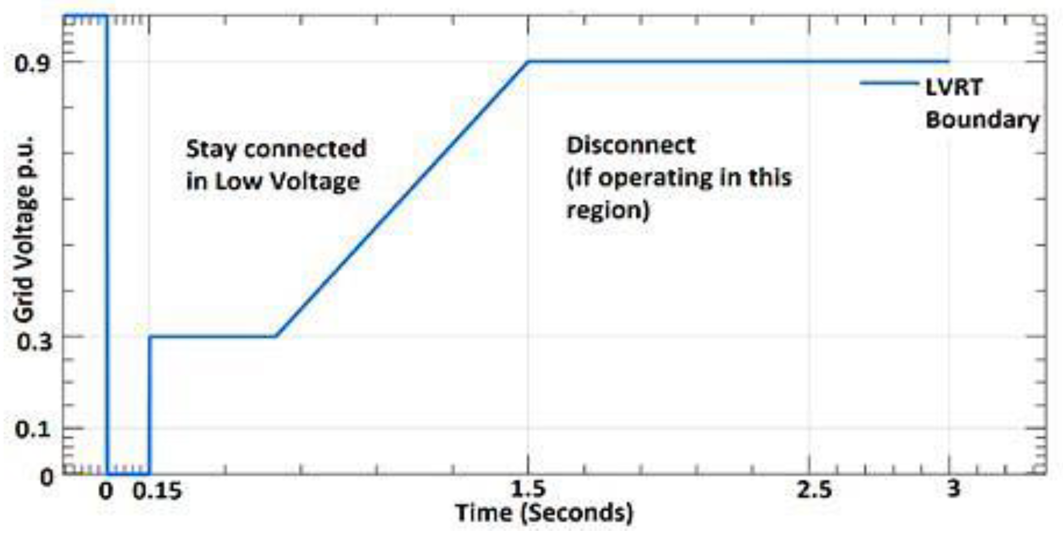
Figure 2.
RCI requirement. [29].
Figure 2.
RCI requirement. [29].
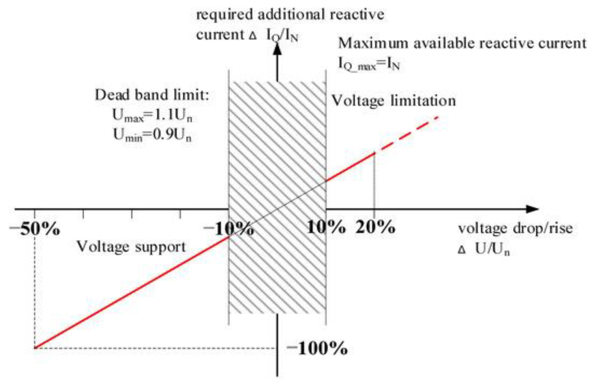
When both FRT and RCI standards are applied during a fault, they determine both the required duration of the DER’s connection to the grid and the reactive current contribution, based on the severity of the voltage drop. This is especially relevant in islanded microgrid scenarios, where DERs act as the primary power sources.
Among all the reviewed methods for short-circuit current calculation, the method proposed in [4] stands out due to its technical advantages and strong compliance with modern grid code standards. Specifically, it takes into account both FRT and RCI requirements, which allows for more accurate modeling of DER behavior during fault conditions. By incorporating advanced DER models that reflect their actual response during faults, this method provides a more realistic calculation of their contribution to the total fault current. In addition, the method can be applied to all types of short-circuit faults, including more complex high impedance faults, which increases its usefulness in real-world scenarios. One of its most important strengths is that it does not rely on the presence of a slack bus, making it suitable for both grid-connected and islanded microgrid operation. This flexibility is especially valuable in modern distribution networks with high DER penetration. For all these reasons, this method is considered the most promising and will be described and analyzed in detail in the following subsection.
A. A Robust Short-Circuit Calculation Method for Microgrids
The method described in the text below is adopted from the articles referenced in [4,5,29,30]. In [4], the method was tested on a real-life microgrid with a high penetration of IBDERs. The results obtained were then compared: on one hand, those calculated using the standard IEC 60909 method, and on the other hand, results from the robust method, in both grid-connected and islanded operating modes. The results of this study indicate that simplified DER models based on the IEC 60909 standard should be applied with caution in microgrids with a high penetration of IBDERs, particularly when the Grid Code requires compliance with FRT and RCI performance characteristics. In such scenarios, the error in calculating short-circuit current during islanded operation can reach up to 36%, potentially leading to incorrect relay protection settings and poor coordination within the microgrid. This issue should be taken into consideration in both grid-connected and islanded modes, although it is more pronounced in the islanded mode. The method is described in detail, as follows.
First, all elements within the microgrid, excluding the DERs, must be properly modeled. This includes loads, transformers, and distribution lines, which are represented according to the methodology outlined in [8]. The key novelty of this method, regarding the modeling step, lies in the incorporation of Grid Code requirements for DERs.
Second, the fault module is incorporated at the faulted node. The fault module is presented in Figure 3. The module is composed of five nodes and four branches. Phase nodes a, b and c represent connection points between microgrid and fault module. Two other nodes are n and reference node. On the three impedance branches, there are two ideal voltage sources with identical magnitudes, but facing away from each other. Voltage magnitude is equal to a pre-fault state of the node m. The fault module can be represented through the following equation:
To model the connection between fault module and microgrid, an incidence matrix T is used. Its dimensions are 3Nx3N1 (where N is number of nodes in microgrid in question). It is defined as:
where:
- I is identity matrix (3x3),
- 0 is zero matrix (3x3).
In this method, short-circuit calculation comes down to calculation of generalized -circuit of the microgrid in question (since the values in the pre-fault circuit are known after the load flow calculation). Durning the decomposition of the faulted network model to its pre-fault state and the generalized -circuit, both ideal voltage sources from traditional electrical machines and ideal voltage sources oriented to fault node are kept in a pre-fault circuit. Therefore, they are left out of the generalized -circuit. Additionally, the contribution from DFIMs and IBDERs must be considered. Since the value of the short-circuit currents of these DERs are slightly higher than their rated values, this difference, also known as excess current, is modeled as current source in the generalized -circuit, in the nodes where these DERs are connected. Excess currents can be calculated using the equation:
where:
- presents total fault current injected by DER k,
- presents total current injected by DER k during the normal operation (pre-fault state),
- presents excess current of DER k.
To summarize this section, the generalized -circuit of a microgrid consists of ideal voltage sources facing away from the fault nodes, and ideal current sources with excess current values, which are active elements and impedances of passive elements.
- a)
- Mathematical Models of the Fault Module in the Generalized -Circuit
In Figure 4, the operation mode of an -th fault module connected to the node k is presented. It is defined by two vectors , and one scalar .
The mathematical model of the fault module in the generalized -circuit in phase domain is described using following equations:
Parameters are defined as (5 - 10). Where represents phase a, b or c.
This mathematical model can be easily transformed into sequence domain, using transformation matrix S:
The model is described using the following equation:
In equation 12 superscript indicates that the value is in sequence domain, where represents direct (positive), inverse (negative), and zero sequence.
- b)
- Mathematical Model of the Generalized -Circuit
The generalized -circuit of a faulted microgrid is described as:
where:
- (3Nx1) represents the injected current vector in the sequence domain in generalized -circuit,
- represents the admittance matrix of the microgrid in the sequence domain,
- (3Nx1) represents the voltage vector of all the nodes within the microgrid vector in the sequence domain in generalized -circuit,
- T (3Nx3N1) represents the incident matrix, and
- (3N1x1) represents the current vector of all fault modules within the microgrid.
Since DERs are present in the microgrid and their short-circuit currents are function of the estimated voltage state in the node of connection in the fault state, the method consists of two steps:
- A preliminary step before iteration, in which the voltages of DER nodes are determined at the moment of the fault.
- Microgrid’s faulted state calculation.
By integrating the equations 12 and 13, the mathematical model of a microgrid’s generalized -circuit in the fault state is given by:
Which can also be expressed as:
Matrix is defined as:
where is a set of faulted node indexes.
Matrixes and are defined as:
Matrix is defined as:
Vector can be determined using the following equation:
Finally, vector is defined as:
- a)
- First Step - Calculation of DER’s Excess Currents
In this step, the goal is to determine the voltage values at the nodes where DERs are connected at the moment of the fault, as the values of these voltages will determine the values of the excess currents, based on the Grid Code requirements, as described above. It is assumed that at the moment of the fault, all DERs are injecting the same current value, as they were in the pre-fault state, as their controllers have still not detected that the fault occurred. Therefore, at this step, after decomposing the microgrid’s faulted state to the pre-fault state and microgrid’s generalized -circuit, excess current values in microgrid’s generalized -circuit are equal to 0. Consequently, vector (in equation 14) is zero vector, in other words vector has known values.
Vector of unknown values , which consists of both short-circuit currents at the fault location and voltage of nodes in generalized -circuit.
It is calculated using the equation below:
When the vector is determined, all the voltage values of the nodes inside the microgrid are calculated using the superposition of voltages calculated in generalized -circuit and those from the pre-fault state. Now, the excess currents in the faulted grid can be calculated based on the selected Grid Code requirements, as previously defined in the Equation (3). For each node where a DER is connected, the excess current is obtained by subtracting the pre-fault current injected by the DER from the total current it injects during the fault:
This expression, originally introduced at the beginning of this Section, defines the excess current considered in the generalized Δ-circuit model.
- b)
- Second Step - Calculation of Microgrid’s Faulted State
Since the excess currents are known from the process described above, the vector is no longer a zero vector, but instead has non-zero elements at the locations where DERs are connected to the microgrid. In other words, vector has known values, as does vector .
The accurate vector of unknown values is now calculated, using equation 22.
The state of the faulted microgrid is calculated using the superposition of the microgrid’s generalized -circuit and the know pre-fault state. This completes the robust method for microgrid fault currents.
Based on the analysis conducted, it can be concluded that the reviewed method is highly suitable for application in microgrids, particularly due to its ability to accurately model IBDERs in accordance with Grid Code requirements. Unlike conventional methods, this approach does not rely on the presence of a slack bus, which makes it applicable in both grid-connected and islanded modes. Its flexibility, broad applicability to complex fault types, and precise consideration of DER behavior during faults were the key reasons it was selected for further testing within this paper. The performance and applicability of this method will be evaluated and presented in the results section that follows.
After analyzing the main challenges and available methods for short-circuit current calculation in microgrids, the next step is to focus on overcurrent relay protection related aspects. As discussed, accurate fault current estimation is essential for proper relay setting and coordination. This becomes especially important in systems with a high share of IBDERs, where traditional protection approaches often fail.
Section 3 starts with an overview of general protection methods used in radial distribution networks, followed by approaches for relay setting and coordination in the presence of DERs. Finally, the section highlights the most promising method selected for detailed analysis, based on its ability to meet modern protection requirements in distribution grids.
3. Relay Protection of Microgrids–State of the Art
Relay protection in microgrids, particularly in AC systems (note that there are also DC microgrids, but they are usually easier to control and protect, and are currently out of scope of this work), presents significant challenges that differ significantly from those in traditional centralized power systems. The growing penetration of DERs introduces variability in fault current magnitudes and directions, complicating conventional protection coordination. In AC microgrids, these challenges are especially pronounced due to the dynamic nature of DER fault contributions, which depend on the operating mode (grid-connected or islanded), fault location, and the type of DER involved. Traditional overcurrent relays, commonly used in radial distribution networks, may not operate reliably under such conditions, particularly when fault current magnitudes are too low to trigger tripping mechanisms. This can lead to issues such as desensitization of protection, delayed tripping, false trips, or even protection system failure [31].
The magnitude of fault current in AC microgrids depends on several factors, including the type of DERs, the operational mode of the microgrid, fault location and type, and load characteristics. IBDERs generally contribute low and controlled fault currents due to built-in current-limiting features, usually not exceeding two times their rated current. In contrast, traditional AC machines, such as synchronous and induction generators, can deliver fault currents up to eight times their nominal value in the sub transient period. This results in non-uniform fault current behavior that complicates coordination of conventional overcurrent protection schemes. The total fault current in a microgrid is a sum of contributions from the utility grid (when connected), inverter-based DERs, rotating-based DERs, and local loads. Each source contributes based on its design, control strategy, and location relative to the fault. This complexity requires advanced protection strategies capable of dynamically adapting to changes in system configuration and DER participation [32,33].
Islanding detection is another critical concern in AC microgrid protection. If not detected and managed correctly, islanding can pose serious safety hazards for utility personnel and increase the risk of equipment damage. Detection methods are generally categorized into passive and active approaches. Passive methods monitor system parameters such as voltage, frequency, harmonics, and the rate of change of frequency. Active methods intentionally introduce small disturbances to detect the absence of the grid. Both methods face limitations in terms of accuracy, reliability, detection speed, and cost. Furthermore, faults that occur on the utility side of the PCC may not immediately result in islanding detection, especially if DERs continue supplying the load, thereby masking the disconnection [34].
Another major issue is protection blinding, which occurs when DERs alter the expected characteristics of fault currents. Protective relays, traditionally calibrated for radial systems with predictable fault levels, may fail to detect or isolate faults accurately in microgrids with high DER penetration [35]. The reduced and sometimes delayed fault current contributions from DERs can lead to missed or delayed trips, prolonged fault clearing times, and compromised system safety.
Resynchronization is essential when transitioning from island to grid-connected operation. This process involves matching the microgrid’s voltage, frequency, and phase angle at the Point of Common Coupling (PCC) with those of the utility grid before reconnection. PCC is the point of microgrids’ connection to the distribution network and in real-life implementation it always represents some kind of switching device, in most cases a circuit breaker.
Improper synchronization can result in transient surges, equipment stress, and unintentional trips. Ensuring a smooth and secure resynchronization process requires advanced control systems and coordination strategies that account for the real-time status of DERs and load conditions [36].
A particularly sensitive issue arises with auto-reclosers. These devices are designed to automatically restore power after temporary faults by reclosing circuit breakers. However, in a microgrid scenario, especially when operating in islanded mode, the utility and microgrid may be functioning asynchronously in terms of frequency and phase. Attempting to reconnect under such conditions can lead to severe voltage and current transients, damaging DER equipment and destabilizing the system. Conventional reclosers also assume that one side of the breaker is energized while the other is passive, which does not hold true in microgrids where active sources may exist on both sides [35].
When configuring and calibrating relay protection within microgrids, additional challenges arise. One of the primary issues is the significant difference in short-circuit current levels depending on the operating mode. For the same fault type and location, short-circuit current in islanded mode can be up to 10 times lower than in grid-connected mode, which is confirmed in research conducted in [20,21,22,38]. In islanded mode of operation, the fault location is supplied exclusively by DERs, making it difficult for traditional protection calibrated for higher fault currents in grid-connected mode to detect and respond appropriately. Therefore, relay protection must be adaptive, capable of switching between operating modes and reliably detecting faults in both.
Another challenge involves the direction of power flow. Under normal conditions and during faults, power typically flows downstream, from the substation toward the loads. However, with high DER penetration across the distribution feeders, a fault can be supplied from both ends, resulting in bidirectional power flow. This undermines the effectiveness of conventional protection schemes, such as overcurrent relays [22].
In response, undervoltage protection has been considered, particularly since inverters reduce their terminal voltage during a fault. However, in microgrids, especially when operating islanded, voltage fluctuations can also occur due to load changes or variations in the battery state of charge. These fluctuations complicate the differentiation between actual faults and normal operating behavior. To address this, superimposed or filtered undervoltage protection has been developed. These variants are less sensitive to slow voltage changes, offering more reliable fault detection, but they also raise system complexity and cost. Rapid battery state changes can still cause sharp voltage drops, which may trigger false fault indications [22].
For unbalanced faults, DERs contribute only balanced (positive-sequence) current, while the terminal voltages remain unbalanced. This makes negative-sequence voltage relays a viable solution, as they respond specifically to unbalanced faults. The idea of a Negative-Sequence circuit breaker was presented in [39] and adequately tested on a microgrid in a laboratory. However, this method does not detect balanced three-phase faults.
DERs are commonly connected via DY transformers, with the Y side grounded on the high-voltage end. In case of ground faults, zero-sequence currents appear in the network, originating not from the DERs but from the grid itself. Thus, installing zero-sequence current relays on the high-voltage side can effectively detect such faults, although this method is limited to ground fault detection only [22].
Finally, during faults, the network impedance drops regardless of the fault current source. This characteristic can be used to determine a threshold impedance value under fault conditions. A distance relay placed at the DER-grid connection point can monitor these impedance changes. If the measured impedance falls below the preset threshold, the relay trips. However, short lines within microgrids make coordination between relays difficult and make the definition of clear protection zones complicated [22].
While DC microgrids present their own distinct protection challenges, primarily due to the lack of natural current zero-crossing and high-speed fault propagation, which is thoroughly addressed in [40], since this section focuses primarily on the relay protection issues within AC microgrids. Understanding and addressing these issues is essential for developing reliable, fast, and selective protection systems that ensure safe operation under all possible conditions.
A study conducted in [41] analyzes grid-supporting-grid-forming inverter during fault event and compares two strategies for current limitation in such scenarios. The Current Saturation Algorithm (CSA) and Virtual Impedance (VI) are compared, and their advantages and limitations were presented. It concludes while CSA has a better response, VI smoothens the systems response, therefore offers better transient stability. The paper also proposed a Hybrid Current Limiting Control strategy (HCL), combining the benefits from both above-mentioned algorithms. However, VI also presents a risk of instability if the fault duration is too long, indicating careful calibration and hybrid approach.
Since technology is rapidly developing and Artificial Intelligence (AI) started to take place in various professions, in some cases even replacing human contribution, some researches are based on implementing AI and Machine Learning (ML) into relay protection methods. Therefore, in the article presented in [40], AI and ML based protection methods were proposed and identified challenges discussed.
In AC microgrids, accurate fault detection is critical for ensuring system stability and safety. Traditional fault detection methods often struggle with distinguishing between different types of faults, particularly in the presence of fluctuating energy inputs from renewable sources. Deep Neural Networks (DNNs) are employed to analyze both historical fault data and real-time system parameters such as voltage, current, and power. These networks are trained to classify fault types and predict faults before they escalate, enabling faster isolation of affected areas and minimizing downtime. However, while DNN offer high accuracy in fault detection, they require substantial training data to recognize fault patterns, and real-time implementation can be computationally expensive. Additionally, the variability of DERs complicates the classification process due to changing system behaviors [40].
In microgrids, the coordination of protection devices (like relays, fuses, and circuit breakers) is crucial to ensure a selective response to faults. With the integration of DERs, the power flow becomes less predictable, complicating the coordination process. Metaheuristic algorithms such as Genetic Algorithms (GA) and Particle Swarm Optimization (PSO) are used to optimize the coordination of protection devices. These algorithms ensure that protection devices are activated in the correct sequence, minimizing the impact of faults and ensuring rapid recovery. Unfortunately, microgrids are complex systems, in terms of dynamic load profiles, and two operational modes, which makes it difficult to achieve perfect coordination. Moreover, the time required to run optimization algorithms can be an issue in real-time operations [40,42].
Voltage regulation in AC microgrids is critical for ensuring that equipment operates within safe voltage limits and to maintain power quality. Variations in DER generation and load demand can cause voltage fluctuations and power quality issues, especially in island mode. Adaptive control algorithms powered by AI, such as those based on fuzzy logic or neural networks, dynamically adjust the voltage setpoints to maintain optimal performance. These algorithms monitor voltage levels in real-time and apply correction actions as needed to prevent over-voltage or under-voltage conditions. Moreover, voltage protection systems that rely on AI must be highly responsive to system changes. The complexity of real-time decision-making can lead to delays or errors in fault conditions, especially when there is a high penetration of intermittent DERs [40,42].
Although AI holds huge potential for improving relay protection setting and coordination, there are still a lot of open questions and challenges that are topics of ongoing research. Some of the challenges are:
- Data quality and availability: AI algorithms rely heavily on accurate, high-quality data to function properly. In microgrids, particularly in remote areas or those with limited communication infrastructure, therefore Incomplete or noisy data can lead to incorrect fault diagnosis, improper protection device activation, and suboptimal system performance. Given that relay protection is one of the most critical—if not the most critical—areas in power systems, the authors believe it is still too early to rely on AI for such functions
- Real-time computation: The complexity of AI algorithms, particularly those used for fault detection and coordination, can lead to high computational requirements, especially when dealing with large amounts of real-time data from various microgrid components. This can limit their practical deployment in scenarios where speed and reliability are crucial.
- Adaptation to Dynamic System Behavior: The presence of DERs in microgrids introduces variability in both generation and load patterns. AI algorithms must constantly adapt to these changes to maintain stable system performance. AI models must be continuously trained and updated to handle new operational scenarios, which increases system complexity. Additionally, the algorithms must be robust enough to function under various operating conditions, including abnormal or transient system behavior.
- Integration with Existing Protection Devices: Many existing protection devices lack the ability to communicate with modern AI-based systems, which creates integration issues. The adaptation of traditional devices to work with new technologies requires substantial upgrades and standardization efforts.
- Cybersecurity Risks: The integration of AI and communication technologies increases the vulnerability of microgrids to cyberattacks. Protecting sensitive data and ensuring secure communication between devices becomes increasingly important. Ensuring that AI systems are secure from attacks while maintaining operational integrity is a significant challenge [40].
Thus, applying AI techniques in critical asks such as relay protection of electrical power systems, should be performed with high caution.
Regarding traditional distribution networks, methods for relay protection setting and coordination have been established in the last several decades and they have been working as expected. However, introduction of DERs, and especially IBDERs complicates the traditional methods and hinders their accuracy.
Since IBDERs cannot be accurately represented within traditional fault calculation methods, new approaches for fault analysis in distribution networks with DERs have been developed in the articles referenced in [4,5,29,30], as discussed in previous sections. In most of these works, IBDERs are modeled as constant current sources injecting currents in phase with the voltages at their points of connection. However, distribution codes clearly define FRT requirements, mandating that IBDERs remain connected during faults and inject reactive power to support faster network recovery [45,46,47]. Therefore, DER models must incorporate these FRT requirements.
Several new protection methods for distribution networks with IBDERs have been proposed in [48,49,50]. However, these methods rely on simplified models where IBDER fault currents are limited to 1.5 times their rated values and do not account for reactive current injection as required by FRT standards. Furthermore, these protection strategies assume that protection devices are installed on nearly every feeder section. While this would ensure high reliability, such an approach is economically unfeasible for real-life distribution networks. In reality, protection devices are typically placed at the beginning of feeders, and in some cases, at midpoints or on critical laterals [43,44].
Similarly, protection methods for DFIM-integrated networks are proposed in [51,52,53,54]. Yet, most of these works also assume total loss of current control by DFIMs during any fault, modeling them as asynchronous machines. Only the method in [53] recognizes the potential for DFIMs to maintain current control during mild faults, but the models are time-domain based, making them computationally intensive and impractical for large-scale relay protection studies. Additionally, like earlier approaches, these methods also assume dense deployment of protection devices across the network, which is not realistic.
From the review of existing literature, it is evident that many of the proposed protection strategies are highly complex and often depend on a dense deployment of protection devices across the network. Although such approaches can improve reliability and precision, they are not suitable for practical microgrid applications due to high installation and maintenance costs. Even in larger distribution networks, protection devices are usually placed only at the beginning of feeders and, in some cases, at critical points, making the implementation of complex protection architectures unrealistic. These economic limitations underline the need for simpler and more cost-effective protection solutions that can still meet the required reliability standards.
In addition to financial constraints, many of the existing overcurrent protection strategies also present significant technical challenges. Many of them do not properly model the behavior of inverter-based DERs and DFIMs during faults, especially in accordance with modern Grid Code requirements, such as FRT. Additionally, islanded operation is often ignored or overly simplified, despite being a key part of microgrid functionality. Because of these limitations, existing methods often prove either unreliable or too inflexible to adapt to real-life conditions.
Given the challenges and limitations outlined above, in the following section, a relatively novel adaptive overcurrent relay protection method, which overcomes most of the aforementioned challenges will be presented [6]. However, it needs to be noted at this place, the following method is tailored for radial distribution grids, with an existing slack bus, which introduces some technical challenges when microgrids are considered. These challenges will also be discussed in the following sections, providing a basis for recommendations for future research directions.
Adaptive Relay Protection for Distribution Grids with High DER Penetration
In the following text, a relatively new method for relay protection setting and coordination in radial distribution networks with IBDERs, will be described. Since the challenges regarding relay protection coordination in distribution networks with high DER penetration were presented earlier in the text, this method suggests a solution. Before describing the method, overcurrent relay setting in radial distribution networks will be addressed.
Setting the relay involves setting two variables: tripping current and time. In other words, current-time characteristic, which defines relay tripping time based on the fault current. These characteristics are different for different relays. In order of magnitude, the current is in kA and tripping time is in ms. The current setting is determined based on the maximum allowable current which certain protected element can withstand, and tripping time is set in a way where selectivity level between main-backup relay pair is secured. In other words, the main relay must trip before the backup relay if the fault occurs in the primary zone of protection [55].
For current setting of the instantaneous overcurrent relay maximum value of the fault current is used for given network configuration. In distribution networks with high DER penetration, maximum fault current through a relay is achieved when all downstream DERs are disconnected and all DERs upstream (looking from the relay location) connected [43,44]. For the short-circuit calculation, the method described in the previous paragraph can be used.
Regarding the overcurrent protection, to achieve acceptable selectivity level for all fault current values, it is enough to achieve selectivity level for the maximum fault current value. In other words, setting the tripping time for relay protection is based on the short-circuit calculation for both network condition and configuration which provide maximum short-circuit current through a protective device. Finally, selectivity has been met if the tripping time of a backup relay is higher than the main one for the maximum value of the short-circuit current, when a fault occurs at the primary zone of protection of the main relay. The difference between a tripping time is called selectivity level.
Specifically, in Figure 5, if the tripping time of the relay R1, as a backup relay is greater than tripping time of relay R2 as the main one for the fault on the Bus 2, selectivity has been met.
The previously established overcurrent relay protection settings are suitable for radial distribution networks in the absence of DERs, where power flow is strictly unidirectional and fault current contributions come solely from the main substation and traditional synchronous machines. However, with the integration of DERs into the network, these traditional protection methods are no longer fully applicable.
As illustrated in Figure 5, let us consider a simplified case with only relays R1, R2, and DER1. If a fault occurs, DER1 contributes to the fault current, affecting both its magnitude and direction. This bidirectional contribution violates the basic assumption of unidirectional fault current flow in radial systems, compromising the coordination and selectivity of relays R1 and R2.
For example, if the fault occurs at the transformer bus, both the main transformer and DER1 supply fault current from opposite directions. As a result, the relays may not detect the fault correctly or operate in the correct sequence, leading to sensitivity and selectivity issues. Similarly, if the fault is located downstream, the current through R1 may be significantly lower than expected due to DER1’s upstream contribution, which further disturbs the designed current ratio used for relay coordination.
Therefore, in reference [6] a relatively new method for relay protection setting and calibration in distribution networks with high DER penetration is proposed.
In contrast to traditional methods, the new method proposes time intervals from the moment of the fault until relay tripping time. These time intervals are determined based on the DER disconnection time from the grid in accordance with a selected FRT requirement, presented in Figure 6. This general requirement can be easily adapted to fit the FRT requirement of any country. Sensitivity and coordination of the relay protection is checked in every interval, with short-circuit current values that are affected by number of DERs connected to the grid at given time interval. Therefore, relay tripping time is calculated over again for every interval, considering the change in short-circuit current.
Let us now consider coordination between main (R2) – backup (R1) relay pair on Figure 5. Coordination and selectivity for this pair of relays is verified in the case of a short-circuit at the end of the primary zone of the protection of relay R2.
As it was explained in the previous paragraph, according to the FRT requirement, after the fault occurs, all DERs must stay connected for the certain period of time. Therefore, as shown in the Figure 6, during the first 150 ms after the fault occurs, all DERs remain connected to the grid. It is important to note that the analyzed method can operate accurately under any FRT requirement. In this case, the German FRT requirement was selected because it is considered one of the most stringent.
Consequently, the first time-interval of interest spans from the fault occurrence to 150 ms (marked as Interval I). The same approach is used to determine time intervals for any FRT requirement. Within this interval, the complete short-circuit current calculation is performed, considering the IBDER and DFIM models described earlier.
The fault current through relay R2 in this interval is , and through R1 is . Their tripping times are and , respectively.
If is less than 150 ms, R2 trips before DER disconnection, and the calculation ends. If exceeds 150 ms, a second time interval is defined—from 150 ms to (Interval II on Figure 6). During this period, DER disconnection times are calculated based on the voltage profile using equation below which is based on the LVRT characteristic:
where represents the relative voltage deviation and is calculated as the ratio of the positive-sequence voltage component at the DER connection node to the nominal voltage value of that node using the equation:
If at least one DER disconnects during this interval, a second short-circuit calculation is carried out, excluding those DERs.
New short-circuit currents and are determined, and corresponding relay operating times and are calculated. Since relays were already exposed to current during the first interval, corrected relay times are calculated using the following equations:
Finally, the approach checks whether any remaining DERs will disconnect between 150 ms and If not, the calculation ends. If they do, the cycle repeats until no DER disconnects before R2 trips.
This calculation must be repeated for each main-backup relay pair in the network and is also applicable for recloser-fuse coordination [6].
This is where the calculation ends. In the article [6], the robust method was tested on the IEEE 37 and verified on the real-life distribution network. Based on the results obtained in the research, it was concluded that the method is useful and applicable for real-life distribution networks with high DER penetration.
In order to test the applicability of the presented method for overcurrent relay protection of microgrids, the next step in this paper is to apply the described method on a real-life microgrid. The goal is to estimate how the method performs under realistic conditions, including varying fault type and location, dynamic power flows, and DER contributions. Once the simulation results are obtained, a detailed discussion will follow, focusing on the method’s applicability, observed benefits, and identified limitations. Finally, key conclusions will be drawn that will serve as a foundation for future research and possible improvements in this domain.
To ensure a comprehensive evaluation, both the short-circuit calculation and the adaptive overcurrent protection method, are applied to the selected real-life microgrid. Their performance is analyzed through a series of targeted simulation scenarios, aimed at verifying the validity of their theoretical assumptions and assessing their practical relevance under complex operating conditions.
The results of these simulations, along with a comparative analysis and discussion, are presented in the following section.
4. Calculation Results
The following tests, on a real-life microgrid system, were performed exclusively for better understanding of the current state of the art and existing methods for short-circuit calculation and relay protection coordination, especially for two selected methods. Later in the paper, pros and cons will be discussed regarding both methods, and the conclusions regarding future research directions in short circuit calculation and overcurrent relay protection of microgrids will be derived.
The testing microgrid in question is Case Western Reserve University (CWRU) campus microgrid, located in Cleveland, Ohio [56]. All the microgrid components described in further text can be seen in the Figure below. Short-circuit faults will be simulated on Buses 2 and 5 (yellow lightning illustrated in Figure 7). For each bus, two boundary fault conditions will be analyzed: single-phase (lowest fault current) and three-phase short-circuits (highest fault current). The single-phase fault is selected as one of the most common fault types in distribution networks and typically results in the lowest fault current. Conversely, the three-phase fault produces the highest fault current and represents the most severe fault condition, making it essential for evaluating the worst-case scenario. Additionally, on each bus, both fault types will be tested under grid-connected and islanded modes of microgrid operation.
The microgrid consists of 28 three-phase nodes, and Bus 1 being the source node which is connected to the Utility grid at the PCC. Three voltage levels exist within the microgrid, and these are: 11.2 kV, 0.48 kV and 0.207 kV.
The Utility grid has a three-phase short-circuit power of 1000MVA and X/R=22. Two identical diesel generators are connected in Bus 4 and 5. Their rated power is 200 kVA.
Wind turbine with rated power and the Energy Storage System, with rated powers of 60 and 40 kVA, respectively are connected to the Bus 6. PV Array with the rated power of 40 kVA is connected to the Bus 13.
Line impedance of cables L1, L2, L3, and L4 is , while L1 and L2 being 150 ft long and L3 and L4 200 ft. Line impedance of L5, L6, L7, L8, L9, and L10 is . The length of these cables is 400 ft. At the end of these cables Lump loads are located, each having a rated power of 60 kVA. Single Motor load is connected to the Bus 9 with the rated power of 40 kW.
Transformers TG1 and TG2 have parameters: 0.48/11.2 kV, , 2 MVA, Z=5.75%, X/R=6.
Transformers T1-T4 have parameters: 11.2/0.48 kV, , 0.5 MVA, Z=5.75%, X/R=6.
Transformers T5-T10 have parameters: 0.48/0.207 kV, , 0.25 MVA, Z=5.75%, X/R=3.
Microgrid modeling and fault simulation were conducted in the software application ETAP (Electrical Transient Analyzer Program). ETAP is an advanced software application used for modeling, analysis, and simulation of electrical power systems. It provides tools such as short-circuit analysis, load flow studies, protective device coordination, etc. It is widely used in both academia and industrial applications for designing and verifying the performance of power systems.
The following subsections present short-circuit analyses for Buses 2 and 5. These buses were chosen to represent different conditions within the microgrid. For each location, both single-phase and three-phase faults are simulated to cover a range of fault severities. Each fault type is also tested under grid-connected and islanded modes to evaluate the microgrid’s behavior in different operating scenarios.
For each analysis, a table will be provided showing the short-circuit current magnitude at the faulted bus and at buses where DERs are connected, labeled as and expressed in kA. Additionally, the relative voltage deviation at each of these buses will be shown, labeled as and expressed as a percentage.
After the short-circuit analyses, the subsequent section will focus on the relay protection setting method previously described. This will involve evaluating the coordination and settings of protective relays based on the simulation results obtained using ETAP, to ensure appropriate response to various fault conditions and maintain system reliability.
A. Short-Circuit at Bus 2
In this subsection, the short-circuit location is set at Bus 2, as shown in Figure 7. This location is specifically selected because Bus 2 is connected to various loads and DERs on one side, while being relatively close to the utility grid on the other. This makes it an ideal point to demonstrate the contributions of both the utility grid and DERs to the total short-circuit current in both grid-connected and islanded operating modes. Firstly, a three-phase short-circuit study will be conducted, followed by a single-phase short-circuit.
1) Three-Phase Short-Circuit Study
A three-phase short-circuit simulation was conducted at Bus 2 for both grid-connected and islanded operating modes. In the grid-connected mode, the fault current amplitude reached approximately 52 kA, while in the islanded mode it was significantly lower, only around 260 A. This results in a difference of nearly 200 times, clearly highlighting the dominant contribution of the utility grid to the total short-circuit current. These results confirm the expected behavior, as Bus 2 was deliberately chosen due to its close connection to the utility grid. However, the difference in magnitude, reaching up to 200 times, is significant. As mentioned in the previous section, this difference typically reaches up to 11 times when switching between microgrid operation modes. The primary reason lies in the Utility Grid’s three-phase short-circuit power, which is 1000 MVA. In contrast, the other sources within the grid have generation capacities not exceeding 200 kW. When combined with the fault location, these factors explain the substantial diversity in short-circuit current magnitudes.
The following table presents the short-circuit current magnitudes at the buses of interest for a fault occurring at Bus 2, along with the relative voltage deviation at each of these buses. Values highlighted in red represent the short-circuit current at Bus 2 for both grid-connected and islanded modes of operation. These values will also be referenced in the analyses that follow.

Table 1.
Three-phase short-circuit current and voltage deviation for faulted Bus 2.
| THREE-PHASE SHORT-CIRCUIT | ||||
| Mode | Grid-connected | Islanded | ||
| Parameter | [kA] | [%] | [kA] | [%] |
| Bus 2 | 51.807 | 0 | 0.262 | 0 |
| Bus 5 | 1.776 | 4.17 | 1.776 | 4.17 |
| Bus 6 | 1.097 | 12.33 | 1.097 | 12.33 |
| Bus 13 | 0.62 | 7.47 | 0.62 | 7.47 |
Following the analysis of the three-phase short circuit, a single-phase fault was also simulated at Bus 2. This type of fault is among the most common in distribution networks and typically results in significantly lower fault current levels. The goal of this analysis is to observe system behavior under asymmetrical fault conditions and to further evaluate the contributions of DERs and the utility grid in both operating modes.
2) Single-Phase Short-Circuit Study
A single-phase short-circuit simulation was performed on phase A at Bus 2 for both grid-connected and islanded operating modes. In the grid-connected case, the fault current reached approximately 25 kA, while in the islanded mode it dropped drastically to just around 380 A. Again, this extreme difference clearly emphasizes the minimal fault current contribution from DERs when the system operates in islanded mode. Looking at the single-line diagram of the network in Figure 7, it is evident that the DERs are located far from Bus 2, which is one of the reasons for their limited impact in this case. The simulation results of interest are shown in the Table below, as was done for the previous case.
Table 2.
Single-phase short-circuit current and voltage deviation for faulted Bus 2.
| SINGLE-PHASE SHORT-CIRCUIT | |||||
| Mode | Grid-connected | Islanded | |||
| Parameter | [kA] | [%] | [kA] | [%] | |
| Bus 2 | 25.529 | 0 | 0.384 | 0 | |
| Bus 5 | 0.489 | 50.21 | 1.513 | 32.29 | |
| Bus 6 | 0 | 88.26 | 0.035 | 56.87 | |
| Bus 13 | 0.138 | 87.42 | 0.051 | 55.76 | |
In summary, analyzing the results given in the tables above it can be concluded that Utility grid contributes significantly to the total fault current at the Bus 2 because of its location. This clearly demonstrates the dominant influence of the utility grid in supplying fault current. Both three and single-phase fault results show the limited contribution of DERs in islanded mode, partly due to their distance from Bus 2 as seen in the network diagram. Moreover, the previously described short-circuit calculation method has proven to accurately capture fault currents in both microgrid operating modes and for different fault types, as demonstrated here.
The following subsection focuses on Bus 5, where similar fault simulations are conducted to evaluate the behavior of both fault types under grid-connected and islanded conditions, providing further insight into the microgrid’s overall fault response.
B. Short-Circuit at Bus 5
In this subsection, the short-circuit location is set at Bus 5, and it is specifically selected because it is the connection point of Diesel Generator 2 (DG2), making it suitable for observing how the presence of a local generation source affects short-circuit current levels. Unlike the previous case at Bus 2, this fault location is not as close to the utility grid, though it is not too far either. This setup allows us to compare the influence of the utility grid and local DERs under different conditions. As before, both three-phase and single-phase faults will be analyzed in grid-connected and islanded operating modes, starting with the three-phase short-circuit study.
1) Three-Phase Short-Circuit Study
A three-phase short-circuit simulation was carried out at Bus 5 under both grid-connected and islanded operating conditions. In the grid-connected mode, the fault current amplitude reached approximately 45 kA, while in the islanded mode it was significantly lower, around 5 kA. Although the difference is still substantial, it is notably smaller compared to the case at Bus 2. This is expected, given that the fault at Bus 5 occurs directly at the connection point of the diesel generator, allowing it to contribute more significantly to the fault current even when the microgrid is operating in islanded mode.
As in the previous case, Table 3 shows the output values generated by ETAP for the grid-connected and islanded scenarios. The layout is the same as it was in the study case of the Bus 2, with key parameters highlighted using red color.
Finally, the last case to be tested is the single-phase short-circuit at Bus 5. As previously mentioned, this is the most common type of short-circuit in distribution systems. In this scenario, the fault is again applied to phase A, consistent with the earlier single-phase analysis at Bus 2.
2) Single-Phase Short-Circuit Study
The single-phase short-circuit at Bus 5, applied on phase A, resulted in a fault current of approximately 11 kA in the grid-connected mode and around 5 kA in the islanded mode. Although the difference is still notable, it is significantly smaller than in the case of Bus 2, where the fault current reached about 51 kA in grid-connected mode and around 380 A in islanded mode. This clearly highlights the influence of fault location: Bus 2, being closer to the utility grid, experienced a much stronger contribution from it, especially in the grid-connected scenario. On the contrary, the higher fault current at Bus 5 in islanded mode is due to the fault occurring directly at the connection point of the diesel generator. Detailed parameter explanations are excluded here, as they follow the same format and logic already discussed in previous sections. The simulation results are presented in Table 4.
The short-circuit simulations clearly demonstrate how fault type, location, and operating mode significantly influence the magnitude of fault currents in a microgrid. As expected, three-phase faults produced the highest current levels, while single-phase faults resulted in considerably lower values. The comparison between Bus 2 and Bus 5 highlights the importance of fault location, proximity to the utility grid drastically increases fault current in grid-connected mode, while local sources like diesel generators contribute more in islanded conditions when faults occur nearby.
The short-circuit calculation method described earlier proved to be highly useful and accurate in modeling fault behavior in microgrids. The consistency and reliability of the results across different fault types and operating modes confirm its practical applicability in real-life protection studies.
With short-circuit levels now established across different scenarios, the next step involves analyzing the performance of the selected overcurrent relay protection method.
C. Relay Protection Coordination for Faulted Buses 2 And 5
The study was once again conducted in ETAP software using the Star-Protection and Coordination mode, which is specialized in relay protection coordination. In this case, three-phase faults were simulated at Buses 2 and 5, maintaining consistency with the previous section, where short-circuit analysis was performed on the same buses. However, this study was conducted only in grid-connected mode, due to certain limitations of the method used for relay protection settings and coordination. These limitations will be discussed after presenting the results.
It is very important to note that ETAP Star does not have an option to integrate certain mathematical functions and calculate based on them. Instead, an official standard is chosen (IEC, ANSI, IEEE, etc.), and relay protection coordination is conducted accordingly. In Figures 8 and 9, relay reaction times were listed for a three-phase fault in Buses 2 and 5, respectively. These reaction times were calculated using the IEC standard and the traditional relay protection method for radial distribution networks, where selectivity is set solely based on the relay location in the network and the short-circuit current magnitude at that location. In this method, relays are set according to their time-current characteristic curves, which determine operating time as a function of the fault current magnitude. The closer a relay to the slack bus, the later should it operate (serving as backup protection for relays in the lower network layers) in order to avoid immediate disconnection of larger parts of the network that are not affected by the fault.
On the other hand, the chosen method for relay protection coordination in distribution networks with high DER penetration takes into account DERs’ disconnection times according to the FRT standard and calculates relay reaction times in separate time intervals, based on those disconnection times. Discussion will be carried out in the following text and a comparison will be made regarding those two approaches.
The analysis was performed on the same microgrid as in the previous study, the CWRU campus microgrid, with only minor differences on the 11.2 kV side of the network. As illustrated in Figure 7, High Voltage Circuit Breakers (HVCBs) must be properly set and coordinated using Current Transformers (CTs) and Overcurrent Relays (OCRs). Each HVCB is equipped with its own dedicated CT and OCR pair. When a fault occurs, the CT detects and scales the fault current according to its ratio, allowing the OCR to process the signal without damage. Based on the recalculated fault current, the OCR then determines whether or not the corresponding HVCB should trip.
In the following paragraph, results given in Figures 8 and 9 using the traditional method for relay protection in distribution networks will be discussed. After that, focus will shift towards the method of interest for coordination in distribution networks with high DER penetration.
1) Traditional Method for Relay Protection Coordination
Table 5 and Table 6, respectively, present the results for three-phase faults occurring on Buses 2 and 5, displaying the sequence and timing of relay and corresponding circuit breaker operations. The relevant data in each table is highlighted with a green rectangle. The left column indicates the reaction time in ms, while the right column specifies the device that responded at that moment.
By examining Table 5, together with the relay and circuit breaker positions shown in Figure 7, the obtained results appear to be very reasonable in terms of protection selectivity. Specifically, Relay 2 was the first to respond, tripping HVCB2, which is appropriate since HVCB2 is located closest to Bus 2, where the fault occurred. In case HVCB2 fails to operate, Relay 12 serves as backup and trips the breaker at the PPC, thereby disconnecting the faulty section from the grid. As seen in the table, a clear level of selectivity has been achieved.
The other eight breakers listed are Low Voltage Circuit Breakers (LVCBs) on the 0.48 kV side. These are connected DERs and local loads, and are expected to operate later, which makes sense considering their downstream position in the network hierarchy.
The same principle applies to the fault at Bus 5, as shown in the results presented in Table 6. Relay 10 is the first to operate, tripping HVCB10, which is expected, given that HVCB10 is the closest breaker to Bus 5. If HVCB10 were to fail, the protection system would continue to operate in a selective manner: Relay 3 would then respond and trip HVCB3, followed, as a last level of backup, by Relay 12 tripping the breaker at the PPC.
The results obtained for the grid-connected mode, as shown in Table 5 and Table 6, confirm the proper functioning of the traditional relay protection method. The relay coordination logic responded selectively and appropriately in both fault scenarios, at Bus 2 and Bus 5, ensuring that the nearest protection devices operated first, while backup relays followed in a well-ordered sequence.
2) Adaptive Relay Protection for Distribution Grids With High DER Penetration
Unlike the previous method, this approach takes into account the FRT standard, displayed in Figure 6, thereby considering the period of time during which all DERs must remain connected to the grid depending on the relative voltage drop at the point of connection. Based on these time intervals, the relay operating times are calculated accordingly. DER disconnection times are calculated using the equation 23, where the relative voltage drop is used from the Table 1 and Table 3, for three-phase short-circuit in Buses 2 and 5, respectively.
Equation 23 is, again due to simplicity, displayed below:
Calculated disconnection times are displayed in Table 5 and Table 6. In the left colums, Buses with associated DER, and in the right disconnection times in ms are displayed.
Firstly, the results of the three-phase fault at Bus 2 will be discussed, followed by a discussion of the results on Bus 5.
- a) Three-Phase Short-Circuit Simulated in Bus 2
According to the adaptive relay protection method and based on the FRT requirement shown in Figure 6, if the relay protecting the bus operates during the first interval, meaning it trips while all DERs are still connected to the network, the calculation process stops at that point. In this case, as shown in Table 5, Relay_2 operates at 20 ms, which falls within the first interval while all DERs are still connected. Therefore, no further calculation is required.
- b) Three-Phase Short-Circuit Simulated in Bus 5
In contrast to previous subsection, for the three-phase short-circuit simulated at Bus 5, Relay_10, which is responsible for protecting this bus, operates at 390 ms (Table 6). Since this value exceeds 150 ms, further calculations are required. Table 8 presents the DER disconnection times, while Table 6 shows the relay reaction times within the first interval. For the continuation of the calculation process, the corrected relay time equations are applied once again (these correspond to equations 25 and 26 from the previous section:
Both equations mentioned above are necessary because this method is applied to a main–backup relay pair. In this scenario, for the fault at Bus 5, Relay_10 serves as the main relay, while Relay_3 acts as its backup.
After applying the adaptive relay protection method and calculating the values using the two equations, new relay reaction times were obtained for the main–backup pair. Instead of the original 390 ms, the updated reaction time for Relay_10 is 508 ms, while the recalculated time for its backup, Relay_3, is 1280 ms, compared to the initial 1837 ms shown in Table 6. Both of these updated times fall within Interval II of the FRT requirement, demonstrating that the adaptive relay protection method provides a more accurate estimation of relay reaction times compared to the traditional approach. This is because it considers both the FRT requirements and the real-time conditions in the network, allowing for a dynamic and more realistic coordination of protection devices.
As presented, this method considers IBDERs and their specific FRT requirements, with high precision. However, this method has a clear limitation when applied outside the grid-connected context. Specifically, it is not suitable for islanded microgrids, where fault current levels are significantly lower and the dynamic behavior of DERs differs. Furthermore, the method is not equipped to handle the most complex scenarios, those involving transitions between islanded and grid-connected modes, or vice versa, where protection settings must dynamically adapt in real time. For this reason, future research will focus on developing an adaptive protection strategy capable of responding accurately in all operational modes of a microgrid, as discussed in the following section.
5. Lessons Learned and Future Work
Both methods reviewed and tested in this study were applied to a real-world microgrid: the campus microgrid of CWRU in North America. The microgrid was simulated using the ETAP software platform, which provided a realistic and detailed environment for analyzing short-circuit behavior and relay protection performance under varying operating conditions, including grid-connected and islanded modes.
One of the key insights gained from this analysis is that the short-circuit calculation method demonstrated full functionality and high accuracy in both microgrid operating modes. Its ability to compute fault currents without requiring the presence of a slack bus makes it particularly suitable for islanded operation, an environment in which many conventional methods fail. Furthermore, by incorporating DER contributions under FRT requirements, the method produces realistic fault current values with minimal error, thereby supporting more accurate and reliable protection system settings.
In contrast, the method for relay protection setting and coordination, although effective in radial distribution systems with a defined slack bus, proved to be inadequate for islanded microgrid operation. As it is designed for radial topologies and explicitly depends on the presence of a slack bus, it cannot be applied in islanded scenarios where these assumptions no longer hold. This limitation presents a significant obstacle for implementing reliable protection in modern, flexible microgrid environments.
These findings highlight the necessity of developing new, robust approaches to relay protection coordination that are adaptable to the structural and operational characteristics of microgrids. While the short-circuit method addresses these needs effectively, the existing protection coordination methods do not.
Accordingly, future work will be focused on designing and implementing an improved method for adaptive relay protection coordination that is suitable for both grid-connected and islanded modes of microgrid operation. The goal is to eliminate the dependency on radial topologies and slack bus configurations and instead develop a dynamic protection scheme that responds to real-time system conditions and DER behavior.
6. Conclusions
In this paper, the authors conducted a comprehensive review of short-circuit calculation and overcurrent relay protection methods in microgrids, with a particular emphasis on identifying their strengths and limitations. The analysis of available literature revealed that most conventional short-circuit calculation methods assume the presence of a slack bus, rely on simplified DER models, and inadequately represent islanded operation, thereby producing inaccurate fault current estimates. Likewise, many existing relay protection strategies are either too complex and economically impractical, requiring dense deployment of protection devices, or fail to adapt to the dynamic behavior of inverter-based DERs under varying operating conditions. To address these shortcomings, one most promising method for short-circuit calculation and one for relay protection were selected for in-depth analysis and evaluation.
Simulation studies carried out on the Case Western Reserve University campus microgrid validated these findings. The robust short-circuit calculation method, based on the generalized Δ-circuit and compliant with FRT/RCI requirements, proved highly accurate in both grid-connected and islanded modes, offering a significant improvement over traditional approach. Conversely, the adaptive relay protection method, while effective for radial distribution systems with a slack bus, demonstrated clear limitations in islanded microgrids with low and variable fault currents. These results underscore the pressing need for topology-independent, adaptive protection coordination frameworks that can dynamically respond to real-time microgrid conditions. Future research should therefore focus on developing robust, cost-effective, and secure overcurrent relay protection methodologies, to ensure reliable protection performance across all operating scenarios of modern microgrids.
References
- Precedence.research. https://www.precedenceresearch.com/microgrid-market.
- L. Mariam, M. Basu, M.F. Colon “Microgrid: Architecture, policy and future trends”, vol 64, 2016, pp 477-489. [CrossRef]
- Di Silvestre, M. L., Favuzza, S., Riva Sanseverino, E., Zizzo, G. “How Decarbonization, Digitalization and Decentralization are Changing Key Power Infrastructures.” Renewable and Sustainable Energy Reviews, vol. 93, 2018, pp. 483– 498. [CrossRef]
- L. V. Strezoski, N. G. Simic and K. A. Loparo, “A Robust Short-circuit Calculation Method for Islanded, Grid-connected, and Utility Microgrids,” in Journal of Modern Power Systems and Clean Energy, vol. 13, no. 1, pp. 325-337, January 2025. [CrossRef]
- Strezoski, L., Prica, M., Loparo, K. A. “Generalized Δ-Circuit Concept for Integration of Distributed Generation in Real-Time Short-Circuit Calculations.” IEEE Transactions on Power Systems, vol. 32, no. 4, 2017, pp. 3237–3245. [CrossRef]
- Luka Strezoski, Iz abela Stefani, Dusko Bekut, Novel method for adaptive relay protection in distribution systems with electronically-coupled DERs, International Journal of Electrical Power & Energy Systems, Volume 116, 2020, 105551, ISSN 0142-0615. [CrossRef]
- Žilović A., Strezoski L., Abbey C., “Microgrids-Current Developments and Challenges”, presented at Energy 2025 Conference, Zlatibor, Serbia, April 2025.
- Strezoski, V. Osnovni proračuni elektroenergetskih sistema (Tom I i Tom II). Novi Sad, Srbija: Fakultet tehničkih nauka, 2017.
- Anderson, P. M. Analysis of Faulted Power Systems. New York, NY, USA: IEEE Press, 1995.
- Bergen, R., Vittal, V. Power System Analysis (2nd ed.). New Jersey: Prentice Hall, 2000.
- Teng, J.-H. “Systematic Short-Circuit-Analysis Method for Unbalanced Distribution Systems.” IEE Generation, Transmission & Distribution, vol. 152, no. 4, July 2005, pp. 549–555. [CrossRef]
- Simić, N., Strezoski, L., Dumnic, B. “Short-Circuit Analysis of DER-Based Microgrids in Connected and Islanded Modes of Operation.” Energies, vol. 14, no. 19, 2021, 6372. [CrossRef]
- Xiaofeng, Z., Soudi, F., Shirmohammadi, D., Cheng, C.S. “A Distribution Short Circuit Analysis Method Using Hybrid Compensation Method.” IEEE Transactions on Power Systems, vol. 10, no. 4, Nov. 1995, pp. 2053–2059. [CrossRef]
- Lin, W. M., Ou, T. C. “Unbalanced Distribution Network Fault Analysis with Hybrid Compensation.” IET Generation, Transmission & Distribution, vol. 1, 2011, pp. 92–100. [CrossRef]
- Teng, J.-H. “Systematic Short-Circuit-Analysis Method for Unbalanced Distribution Systems.” IEE Generation, Transmission & Distribution, vol. 152, no. 4, July 2005, pp. 549–555. [CrossRef]
- Teng, J.-H. “Unsymmetrical Short-Circuit Fault Analysis for Weakly Meshed Distribution Systems.” IEEE Transactions on Power Systems, vol. 25, no. 1, Feb. 2010, pp. 96–105. [CrossRef]
- Jabr, R. A., Dzafic, I. “A Fortescue Approach for Real-Time Short Circuit Computation in Multiphase Distribution Networks.” IEEETransactions on Power Systems, vol. 30, no. 6, Aug. 2015, pp. 3276–3285. [CrossRef]
- Ghanaatian, M., Lotfifard, S. “Sparsity-Based Short-Circuit Analysis of Power Distribution Systems with Inverter-Interfaced Distributed Generators.” IEEE Transactions on Power Systems, vol. 34, no. 6, Nov. 2019, pp. 4857–4868. [CrossRef]
- Kim, I. “Short-Circuit Analysis Models for Unbalanced Inverter-Based Distributed Generation Sources and Loads.” IEEE Transactions on Power Systems, vol. 34, no. 5, Sept. 2019, pp. 3515–3526. [CrossRef]
- Mosetlhe, T. C., Babatunde, O. M., Ayodele, T. R., Yusuff, A. A. “Fault Analysis in a Grid-Tied Microgrid System.” 2022 30th Southern African Universities Power Engineering Conference (SAUPEC), 2022, pp. 1–4. [CrossRef]
- Ghosh, S., Chanda, C.K., Das, J.K. “Performance Analysis of a Grid-Connected Microgrid System Under Fault Condition.” Microsystem Technologies, vol. 28, 2022, pp. 2689–2696. [CrossRef]
- M. Khatib, J. Alvidrez, A. Ellis, Fault Analysis and Detection in Microgrids with High PV Penetration, Semantic Scholar, 2017. [CrossRef]
- Pompodakis, E. E., Strezoski, L., Simić, N., Paspatis, A. G., Alexiadis, M. C., Tsikalakis, A. G., Katsigiannis, Y. A., Karapidakis, E. S. “Short-Circuit Calculation of Droop-Controlled Islanded AC Microgrids with Virtual Impedance Current Limiters.” Electric Power Systems Research, vol. 218, 2023, 109184. [CrossRef]
- L. Strezoski “Modelovanje i fundamentalni proračuni aktivnih distributivnih mreža”, Fakultet tehničkih nauka, Novi Sad, 2021.
- Strezoski, L., Prica, M., Loparo, K. A. “Sequence Domain Calculation of Active Unbalanced Distribution Systems Affected by Complex Short Circuits.” IEEE Transactions on Power Systems, vol. 33, no. 2, 2018, pp. 1891–1902. [CrossRef]
- Strezoski, L., Stefani, I., Bekut, D., Novel method for adaptive relay protection in distribution systems with electronically-coupled DERs, vol 116, 2020. [CrossRef]
- Research gate. https://www.researchgate.net/publication/350716768/figure/Figure 1/AS:1023127588970496@1620944034522/LVRT-Grid-Code-Requirement.ppm.
- MDPI, https://www.mdpi.com/micromachines/micromachines-13 00039/article_deploy/html/images/micromachines-13-00039-g002-550.jpg.
- L. Strezoski, “Complex Short-Circuit Calculation in Unbalanced Distribution Networks with Distributed Energy Resources”, Faculty of Technical Sciences, Novi Sad, 2017.
- Strezoski, V., Bekut, D., “A canonical model for the study of faults in power systems”, IEEE, vol. 6, no. 4, 1991, pp. 1493-1499. [CrossRef]
- Yadav, G.K., Kirar, M.K., Gupta, S.C., Microgrid Protection: A Technological, Challenge-Based, and Future-Oriented Review, Research Square 2025. [CrossRef]
- J. M. Gers and E. J. Holmes, “Protection of electricity distribution networks, 3rd edition,” Prot. Electr. Distrib. Networks, pp. 1–350, 2011.
- K. Kauhaniemi and L. Kumpulainen, Impact of distributed generation on the protection of distribution networks, vol. 1. 2004.
- W. Qian, N. Zhou, J. Wu, Y. Li, Q. Wang, and P. Guo, “Probabilistic Short-Circuit Current in Active Distribution Networks Considering Low Voltage Ride-Through of Photovoltaic Generation,” IEEE Access, vol. 7, pp. 140071–140083, 2019. [CrossRef]
- S. E. Razavi et al., “Impact of distributed generation on protection and voltage regulation of distribution systems: A review,” Renew. Sustain. Energy Rev., vol. 105, no. February, pp. 157–167, 2019. [CrossRef]
- N. W. A. Lidula and A. D. Rajapakse, “Voltage balancing and synchronization of microgrids with highly unbalanced loads,” Renew. Sustain. Energ Rev., vol. 31, pp. 907–920, 2014. [CrossRef]
- Žilović, A. Short circuit calculations in microgrid, Faculty of Technical Sciences, 2024.
- Ghanbari, T., Farjah, E. “Unidirectional Fault Current Limiter: An Efficient Interface Between the Microgrid and Main Network.” IEEE Transactions on Power Systems, vol. 28, no. 2, May 2013, pp. 1591–1598. [CrossRef]
- Ghodrati, M., Borrell, A., Castilla, M., Miret, J., Velasco, M., “Negative-Sequence Virtual Circuit Breaker in Islanded Inverter-Based Microgrids”, IEEE, vol 39., Issue: 10, October 2024. [CrossRef]
- Satpathy, P.R., Ramachandaramurthy, V.K., Padmanaban, S., “Advanced protection technologies for microgrids: Evolution, challenges, and future trends”, vol 58, March 2025. [CrossRef]
- Quria T., Gruson, F., Colas, F., Kestelyn, X., Guillaud, X., “Current limiting algorthms and transient stability analysis of grid-forming VSCs”, vol 189, December 2020. [CrossRef]
- Saldarriaga-Zuluaga, S.D., Lopez-Lezama, J.M., Munoz-Galeano, N., “Adaptive protection coordination scheme in microgrids using directional over-current relays with non-standard characteristics”, April 2021. [CrossRef]
- J. M. Gers, E. J. Holmes: “Protection of electricity distribution networks”, 2nd Ed. London, UK: The Institution of Electrical Engineers; 2004.M. Young, The Technical Writer’s Handbook. Mill Valley, CA: University Science, 1989.
- S.H. Horowitz and A.G. Phadke, Power System Relaying, 4th Ed. West Sussex, UK: John Willey and Sons, 2014. D. P. Kingma and M. Welling, “Auto-encoding variational Bayes,” 2013,.
- M. Tsili, S. Papathanassiou: “A Review of Grid Code Technical Requirements for Wind Farms”, IET Renew. Power Gen., 2009, Vol. 3, No. 3, pp. 308–332, 2009.
- BDWE Bundesverband der Energie und Wasserwirtschaft e.V.: “Guideline for generating plants’ connection to and parallel operation with the medium-voltage network”, 2008.
- Distribution System Operators – ESB Networks, ‘Irish Distribution Code’, 2015.
- M. H. Cintuglu, T. Ma and O. A. Mohammed, “Protection of Autonomous Microgrids Using Agent-Based Distributed Communication,” in IEEE Transactions on Power Delivery, vol. 32, no. 1, pp. 351-360, Feb. 2017.
- H. Muda and P. Jena, “Superimposed Adaptive Sequence Current Based Microgrid Protection: A New Technique,” in IEEE Transactions on Power Delivery, vol. 32, no. 2, pp. 757-767, April 2017.
- S. F. Zarei and M. Parniani, “A Comprehensive Digital Protection Scheme for Low-Voltage Microgrids with Inverter-Based and Conventional Distributed Generations,” in IEEE Transactions on Power Delivery, vol. 32, no. 1, pp. 441-452, Feb. 2017.
- X. Kong, Z. Zhang, X. Yin and M. Wen, “Study of Fault Current Characteristics of the DFIG Considering Dynamic Response of the RSC,” in IEEE Transactions on Energy Conversion, vol. 29, no. 2, pp. 278-287, June 2014.
- S. Chen, N. Tai, C. Fan, J. Liu, S. Hong, “Adaptive distance protection for grounded fault of lines connected with doubly-fed induction generators” IET Generation, Transmission & Distribution; 11(6), pp. 1513–1520, 2017.
- K. A. Saleh, M. S. El Moursi, H. H. Zeineldin, “A new protection scheme considering fault ride through requirements for transmission level interconnected wind parks” IEEE Transaction on Industrial Informatics, 11(6), pp. 1324–1333, Dec. 2015.
- L.V. Strezoski, M. D. Prica, V. A. Katic, B. Dumnic, “Short-circuit modeling of inverter based distributed generators considering the FRT requirements” North American Power Symposium (NAPS), pp. 1-6, Denver, CO. 2016.
- D. Bekut: “Relay Protection”, Stylos, Novi Sad, 1999.
- M. Hong. (2014, Jul.). The Case Western Reserve University campus microgrid. [Online]. Available: https://www.energy.gov/sites/prod/files/ 2014/07/f18/CaseWesternReserveUniversityCampusGrid.pdf.
Figure 3.
Fault module [29].
Figure 3.
Fault module [29].
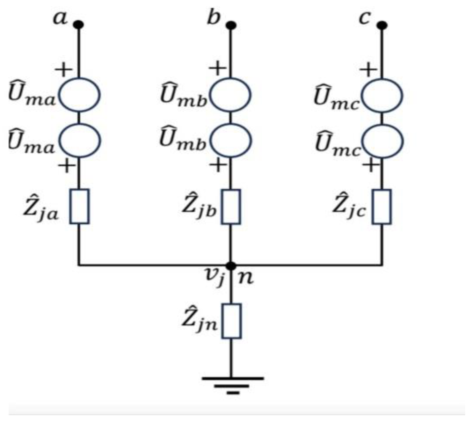
Figure 4.
Fault module in generalized -circuit [29].
Figure 4.
Fault module in generalized -circuit [29].
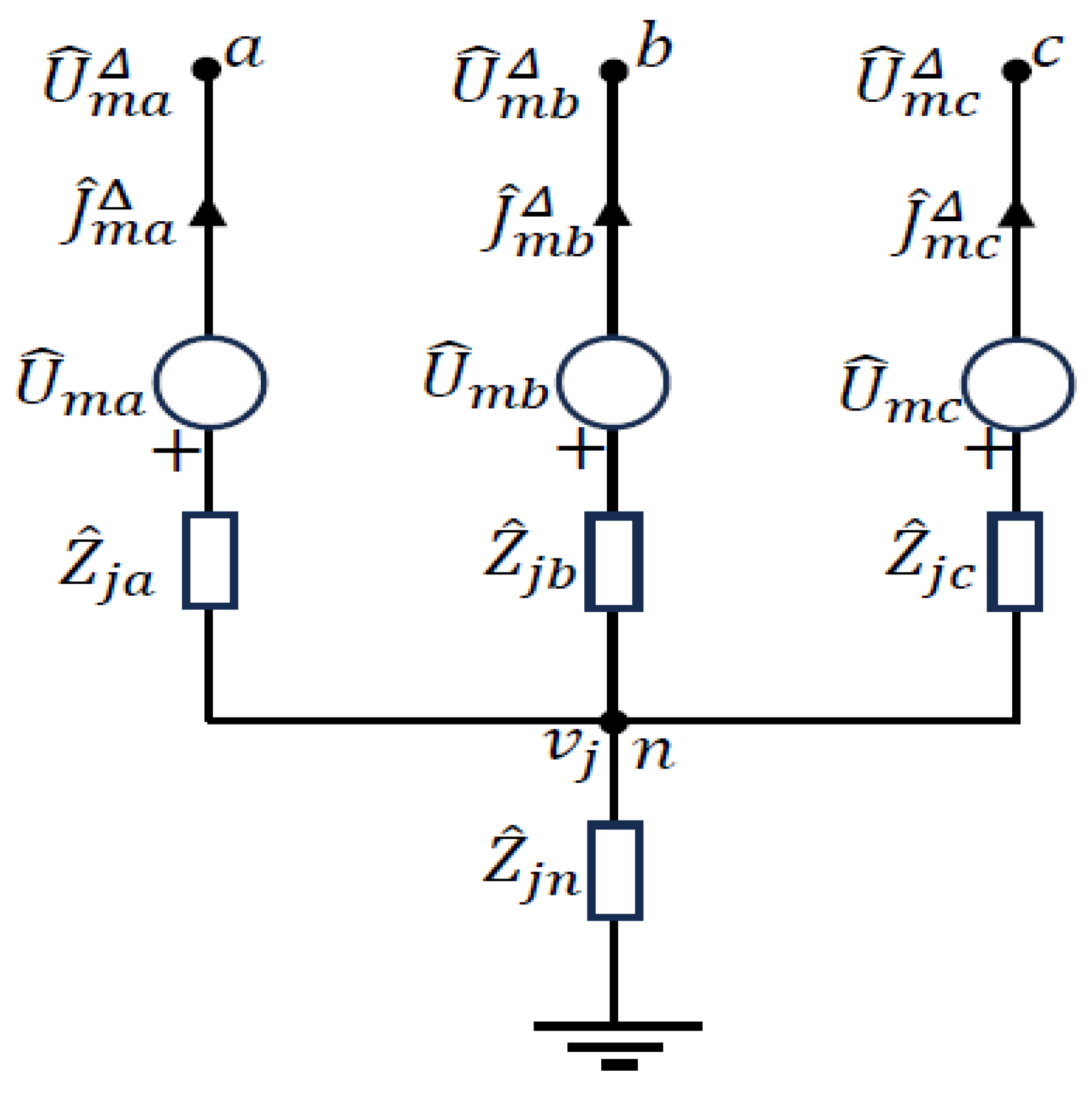
Figure 5.
Single line diagram of a fictional distribution network used in [6].
Figure 5.
Single line diagram of a fictional distribution network used in [6].
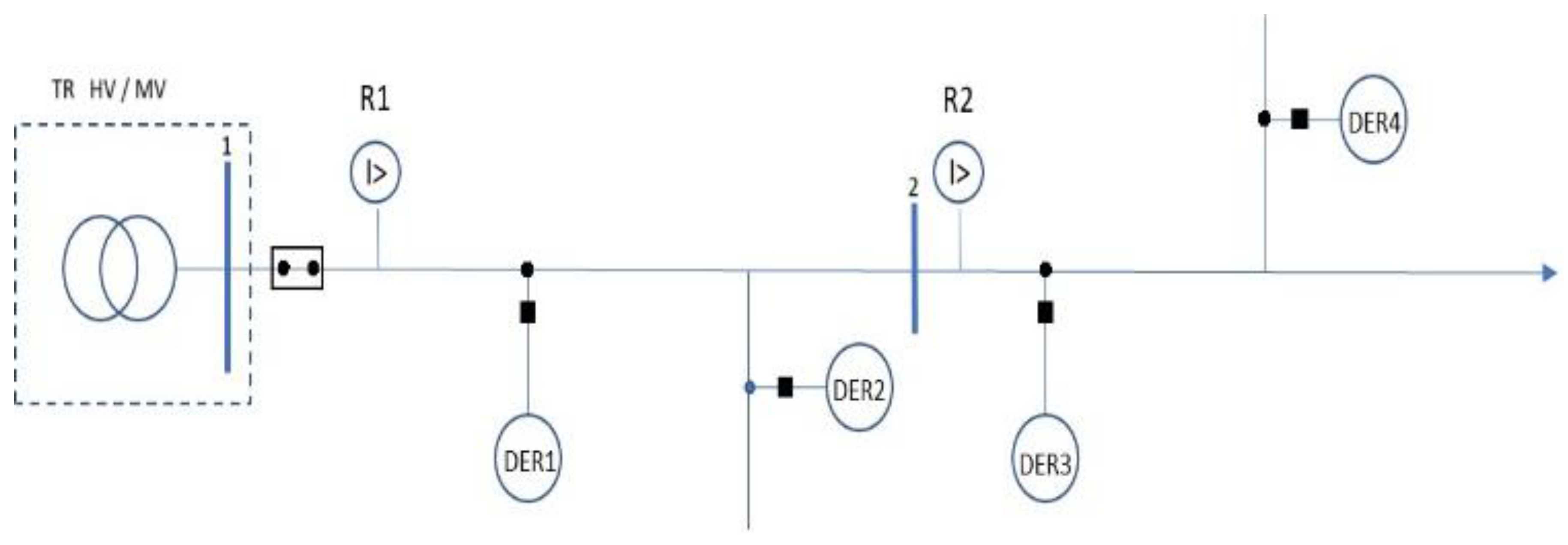
Figure 6.
German FRT standard [6].
Figure 6.
German FRT standard [6].
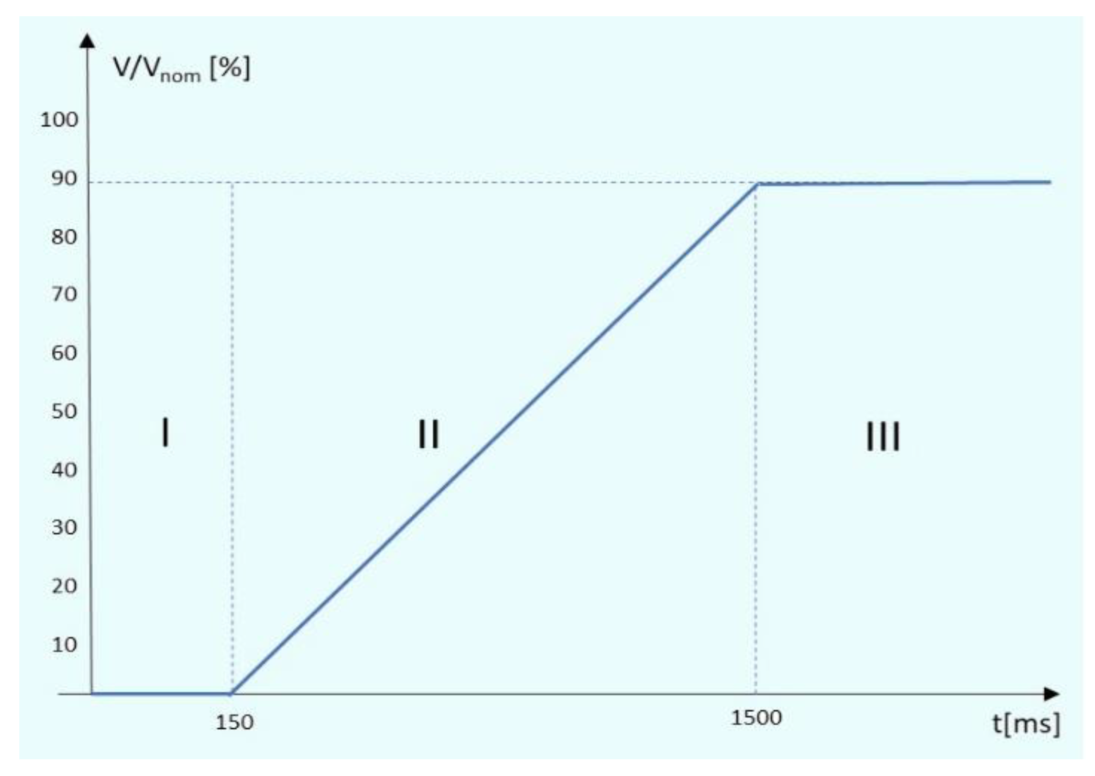
Figure 7.
Single line diagram of CWRU microgrid with faulted Buses 2 and 5.
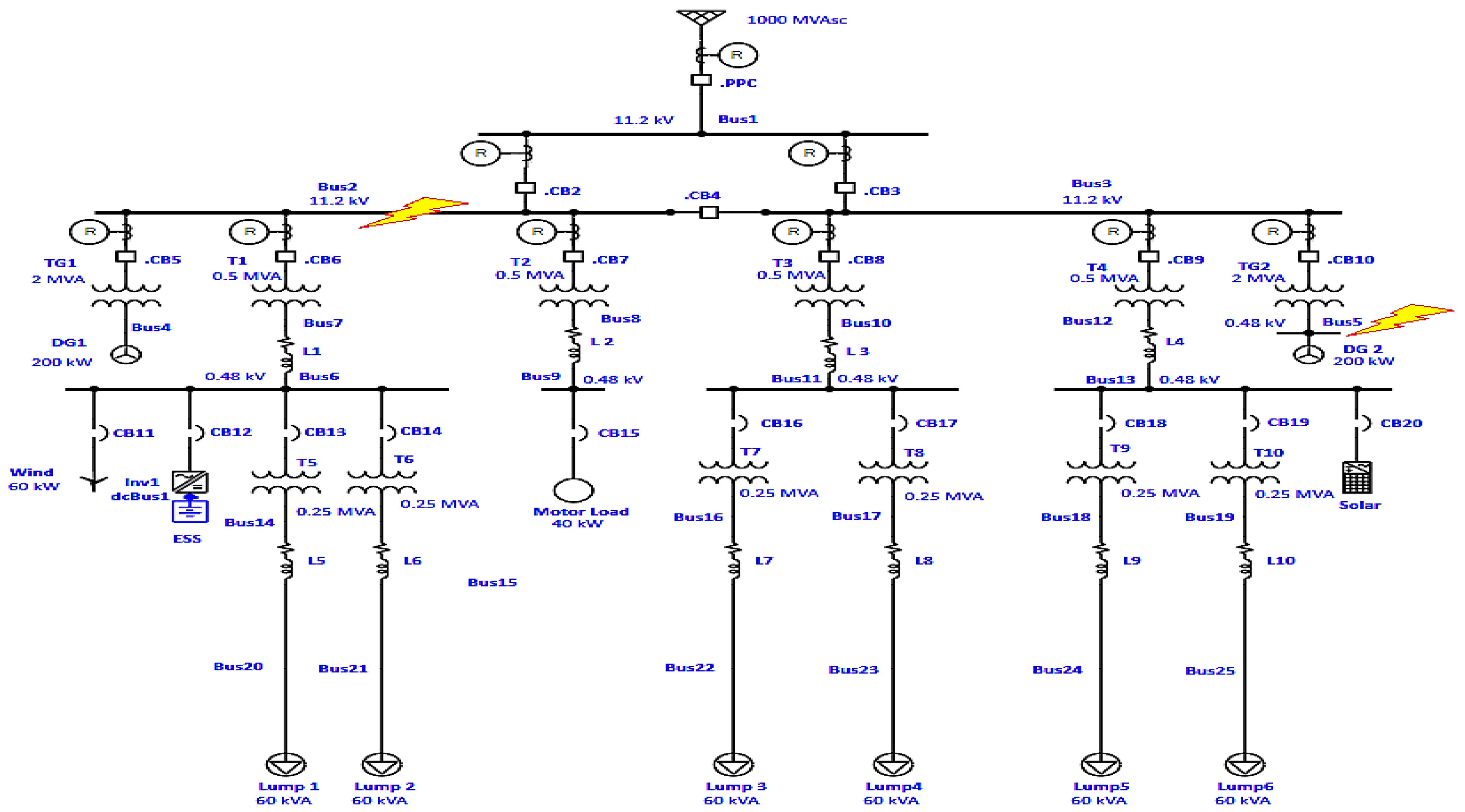
Table 3.
Three-phase short-circuit current and voltage deviation for faulted Bus 5.
| THREE-PHASE SHORT-CIRCUIT | |||||
| Mode | Grid-connected | Islanded | |||
| Parameter | [kA] | [%] | [kA] | [%] | |
| Bus 5 | 45.568 | 0 | 5.564 | 0 | |
| Bus 4 | 0.064 | 101.43 | 1.554 | 8.84 | |
| Bus 6 | 0.038 | 101.47 | 0.506 | 19.79 | |
| Bus 13 | 0.066 | 101.51 | 0.549 | 15.42 | |
Table 4.
Single-phase short-circuit current and voltage deviation for faulted Bus 5.
| SINGLE-PHASE SHORT-CIRCUIT | |||||
| Mode | Grid-connected | Islanded | |||
| Parameter | [kA] | [%] | [kA] | [%] | |
| Bus 5 | 11.768 | 0 | 5.283 | 0 | |
| Bus 4 | 0.011 | 104.74 | 1 | 38.75 | |
| Bus 6 | 0.007 | 104.39 | 0.579 | 51.07 | |
| Bus 13 | 0.05 | 104.58 | 0.371 | 48.96 | |
Table 5.
Result table generated by ETAP for a three-phase short-circuit in grid-connected mode simulated on Bus 2.
Table 5.
Result table generated by ETAP for a three-phase short-circuit in grid-connected mode simulated on Bus 2.
| BUS 2 | |
| Protection device | Reaction time [ms] |
| Relay_2 | 20.1 |
| CB2 | 70.1 |
| Relay_3 | 227 |
| CB3 | 277 |
| Relay12 | 680 |
| PPC | 780 |
| CB11 | 3350 |
| CB15 | 6074 |
| CB16 | 9506 |
| CB17 | 9506 |
| CB18 | 9562 |
| CB19 | 9562 |
| CB13 | 10536 |
| CB14 | 10536 |
Table 6.
Result table generated by ETAP for a three-phase short-circuit in grid-connected mode simulated in Bus 5.
Table 6.
Result table generated by ETAP for a three-phase short-circuit in grid-connected mode simulated in Bus 5.
| BUS 5 | |
| Protection device | Reaction time [ms] |
| Relay_10 | 390 |
| CB10 | 400 |
| Relay_3 | 1837 |
| CB3 | 1887 |
| Relay12 | 2451 |
| PPC | 2551 |
| Relay_2 | 4467 |
| CB2 | 4517 |
Next subsection will focus on applying adaptive relay protection method to the CWRU microgrid and discussing the given results.
Table 7.
DER disconnection times for a three-phase short-circuit simulated on Bus 2 in grid-connected mode.
Table 7.
DER disconnection times for a three-phase short-circuit simulated on Bus 2 in grid-connected mode.
| Buses with connected DERs | Disconnection time [ms] |
| Bus 2 (DG1) | 150 |
| Bus 5 (DG2) | 212.55 |
| Bus 6 (Wind + ESS) | 334.95 |
| Bus 13 (Solar) | 262.05 |
Table 8.
DER disconnection times for a three-phase short-circuit simulated on Bus 5 in grid-connected mode.
Table 8.
DER disconnection times for a three-phase short-circuit simulated on Bus 5 in grid-connected mode.
| Buses with connected DERs | Disconnection time [ms] |
| Bus 5 (DG2) | 150 |
| Bus 1 (DG1) | 1671.45 |
| Bus 6 (Wind + ESS) | 1672.05 |
| Bus 13 (Solar) | 1672.65 |
Disclaimer/Publisher’s Note: The statements, opinions and data contained in all publications are solely those of the individual author(s) and contributor(s) and not of MDPI and/or the editor(s). MDPI and/or the editor(s) disclaim responsibility for any injury to people or property resulting from any ideas, methods, instructions or products referred to in the content. |
© 2025 by the authors. Licensee MDPI, Basel, Switzerland. This article is an open access article distributed under the terms and conditions of the Creative Commons Attribution (CC BY) license (http://creativecommons.org/licenses/by/4.0/).
Copyright: This open access article is published under a Creative Commons CC BY 4.0 license, which permit the free download, distribution, and reuse, provided that the author and preprint are cited in any reuse.


