
Submitted:
03 December 2025
Posted:
05 December 2025
You are already at the latest version
Abstract
This study investigates the differences in flexural behavior of ultra-high-performance concrete (UHPC) arising from variations in test methods and key experimental parameters. Flexural tensile tests were conducted on 51 specimens representing 17 combinations of test variables, including steel fiber length (13 mm and 19.5 mm), specimen cross-sectional dimensions (75×75 mm, 100×100 mm, and 150×150 mm), presence or absence of a notch, and loading configuration (three-point and four-point loading). The tests were performed in accordance with ASTM C1609 and EN 14651, and both deflection and crack mouth opening displacement (CMOD) were normalized by the span length to compare the influence of each parameter. The notched specimens demonstrated significantly improved reliability, exhibiting up to an 8.4-fold reduction in standard deviation due to the consistent initiation of cracking. Regarding size effects, the 75×75 mm specimens showed an overestimation of flexural performance due to the wall effect of fiber distribution, whereas the 100×100 mm and 150×150 mm specimens exhibited similar flexural responses. The comparison of loading configurations revealed that three-point loading produced up to 11.7% higher flexural tensile strength than four-point loading, attributable to concentrated moment–shear interaction and the combined effects of fiber bridging and shear resistance mechanisms. In addition, specimens with longer steel fibers (19.5 mm) exhibited 5.2–9.7% higher flexural performance than those with shorter fibers (13 mm), which is attributed to enhanced interfacial bonding and improved crack dispersion capacity.
Keywords:
flexural tensile test
; ultra-high performance concrete(UHPC)
; specimen size
; notch
; loading method
; steel fiber
1. Introduction
In the 21st century, construction structures have undergone rapid development, becoming larger, more diverse, and increasingly irregular in shape depending on their intended functions and purposes. Consequently, structural materials with higher performance than those traditionally used are now required, leading to continuous advancements in construction materials.
Conventional concrete, widely used in practice, exhibits high compressive strength but low tensile resistance. Due to this intrinsic characteristic, ordinary concrete is prone to cracking, shows low ductility and limited energy absorption capacity, and ultimately undergoes brittle failure. To overcome these shortcomings, fiber-reinforced concrete (FRC), in which short fibers are incorporated into the concrete matrix to enhance its toughness and ductility, was introduced and has been extensively studied [1,2,3,4]. In addition, the increasing demand for FRC and the need for further improvements in material performance have led to the development of ultra-high-performance concrete (UHPC), which maximizes not only compressive strength but also toughness and ductility. Research on UHPC has been actively conducted worldwide [5,6,7,8].
Despite the growing demand for UHPC, standardized testing methods for evaluating its unique material characteristics remain insufficient at the global level. ASTM C1856 [9] is the only standard that specifies test procedures specifically for UHPC. Among various testing items, flexural tensile strength testing for UHPC generally follows the apparatus and procedures specified in ASTM C1609 [10], which was originally established for general FRC. The standard additionally recommends adjusting the dimensions of prismatic specimens depending on the maximum fiber length incorporated in the mixture.
Internationally, the two most widely recognized flexural tensile test standards for FRC are ASTM C1609 [10] and EN 14651 [11]. When flexural tests are conducted using the third-point loading configuration of ASTM C1609, flexural cracking occurs at an arbitrary weak section within the constant-moment region between the applied loads. In contrast, EN 14651 specifies the use of centrally notched prismatic specimens subjected to center-point loading. The notch induces an initial crack at a predetermined location by reducing the tensile area, resulting in smaller variability and generally more conservative flexural performance outcomes [12].
In this study, the differences between ASTM C1609 [10] and EN 14651 [11] flexural tensile test methods, as well as the effects of various test conditions, were experimentally investigated to determine how they influence the flexural behavior of UHPC. Key variables included fiber length, specimen size, loading configuration, and the presence or absence of a notch. Through these parametric flexural tests, this study proposes detailed test conditions that can most accurately and reliably evaluate the flexural behavior of UHPC.
2. Flexural Tensile Test Method for Fiber Reinforced Concrete
The flexural tensile strength test methods for fiber-reinforced concrete can be broadly classified into two categories. The first is the third-point loading method specified in standards such as ASTM C1609 [10] and KS F 2566 [13]. The second is the center-point loading method for notched beams recommended by RILEM TC 162-TDF [14] and standardized in EN 14651 [11].
2.1. ASTM C 1609
The dimensions of the test specimen are determined based on the length of the incorporated fibers. A cross-sectional size of 100 × 100 mm is used for fiber lengths of 50 mm or less, whereas a 150 × 150 mm cross-section is used for fibers longer than 50 mm. The specimen length must be at least three times the specimen depth (H) plus an additional 50 mm, and in all cases, the total length shall not be less than 350 mm.
The loading configuration is the third-point loading method, in which the span length (L) is divided into three equal parts and two loads are applied at the upper third points. A schematic illustration of the testing configuration is shown in Figure 1. The loading rate is adjusted to approximately 900/L, as summarized in Table 1.
2.2. EN 14651
EN 14651 recommends the use of prismatic specimens with a cross-sectional dimension of 150 × 150 mm, a span length of 500 mm, and an overall specimen length between 550 mm and 700 mm. A notch must be introduced at the mid-span on the tensile side by cutting a slit with a width of 5 mm and a height of 25 ± 1 mm.
The loading method involves applying a center-point load on the compression side of a simply supported notched beam. A schematic illustration of the testing setup is provided in Figure 2. The loading rate is controlled at 0.05 mm/min until a crack mouth opening displacement (CMOD) of 0.1 mm is reached, after which it is increased to 0.2 mm/min. The detailed loading procedure is summarized in Table 2.
3. Experiments
3.1. Test Variables
In this study, four major variables were considered: steel fiber length, specimen size, presence or absence of a notch, and loading configuration. A total of 17 specimen types were prepared according to these variables, and the details are summarized in Table 3.
The orientation of steel fibers in UHPC is governed by the casting method, and the resulting fiber orientation significantly influences the tensile performance of UHPC specimens [15,16,17]. Yoo et al. [17] reported that when UHPC was cast along the longitudinal axis of the mold, the initial cracking strength and flexural strength increased by 5.5% and 61%, respectively, compared with specimens cast perpendicular to the mold axis. When long steel fibers are placed in relatively small molds, the confinement of the mold and the wall effect at the specimen boundaries may cause fibers to align parallel to the mold surfaces, potentially leading to an overestimation of tensile performance [12]. To address this issue, ASTM C1856 [9] specifies allowable specimen sizes for flexural testing depending on fiber length, as presented in Table 4. To evaluate the validity of this specification, two fiber lengths—13.0 mm and 19.5 mm—were used in the current study, and the influence of specimen size was examined.
Introducing a notch in the tensile region of a prismatic specimen induces stress concentration at the notch tip, promotes crack initiation at a consistent location, reduces variability in test results, and enhances the reliability of flexural performance evaluation [12,18]. In contrast, flexural tests without a notch—particularly under third-point loading—generally lead to random crack initiation within the constant-moment region between loading points. To examine the differences caused by the presence or absence of a notch, notches were fabricated at proportions consistent with those specified in EN 14651 [11] for each specimen size, as summarized in Table 5.
Specimen size may also affect the flexural tensile performance of UHPC. Thicker specimens may exhibit reduced effective fiber bridging and greater fiber distribution nonuniformity, potentially decreasing flexural performance [19]. Moreover, even in the absence of fibers, increasing specimen size may increase the likelihood of internal flaws or defects due to material heterogeneity, leading to pronounced size effects in post-cracking damage propagation [20]. Therefore, three cross-sectional dimensions—75 × 75 mm, 100 × 100 mm, and 150 × 150 mm—were selected to assess the size effect on UHPC flexural behavior.
Flexural loading methods can be categorized into two main types: the third-point loading method specified in ASTM C1609 [10] and KS F 2566 [13], and the three-point loading method specified in EN 14651 [11]. Both methods were considered as variables in this study to examine their respective advantages, limitations, and differences when applied to UHPC.
3.2. Materials and Specimen Preparation
The UHPC mix was designed with a specified compressive strength of 150 MPa, and the mix details are shown in Table 3 [21]. The water-binder ratio (W/B) was 16.7%, and ordinary portland cement and silica fume with a specific surface area of 100,000 cm2/g were used. The aggregate did not include coarse aggregates, and Australian silica sand with a diameter of 0.5 mm or less and a SiO2 content of 90% or more was used. A filler with a SiO2 content of 90% or more and a density of 2.60 g/cm3 was used, and a dark brown, high-performance polycarboxylic acid-based air-entraining water-reducing agent with a density of 1.01 g/cm3 was used to secure the fluidity of the mix.
The steel fiber was a straight single fiber manufactured using brass-coated high-carbon steel wire. The steel fiber diameter provided by the steel fiber manufacturer is 0.2 mm, the length is 13.0 mm and 19.5 mm, and the minimum tensile strength is 2,650 MPa. The mechanical properties of the steel fiber used are presented in Table 7. The steel fiber was mixed with a volume fraction, Vf, of 2% to produce UHPC.
Based on the mix proportions in Table 6, 17 types of UHPC specimens were cast. Three specimens were prepared for each variable set, resulting in a total of 51 flexural tensile specimens. To minimize variations in fiber orientation and distribution, all specimens were cast along the mold’s longitudinal axis using a crossover-layering method, as illustrated in Figure 3 [22]. Prior to hardening, flowability was evaluated using the ASTM C1437 flow test, and the average flow value from two measurements was 210 mm. Air content was measured following KS F 2449, yielding an average air content of 4.5%.

Table 6.
UHPC mixture proportions.
| W/B (%) |
Unit weight (kg/m3) | ||||||||
|---|---|---|---|---|---|---|---|---|---|
| Water | Cement | Silica fume | Sand | Filler | SF | HWRA | AFA | ASR | |
| 16.7 | 163.6 | 782.4 | 195.6 | 860.7 | 234.7 | 156.0 | 46.9 | 2.3 | 7.8 |
| [Note] SF: steel fiber; HWRA: high-performance water reducing agent; AFA: antifoaming agent; ASR: autogeneous shrinkage reducing agent | |||||||||
Table 7.
Properties of steel fiber.
| Diameter, df (mm) |
Length, lf (mm) |
Aspect ratio (lf / df) |
Tensile strength (MPa) |
|---|---|---|---|
| 0.2 ± 0.01 | 13.0 | 65.0 | 2,650 |
| 19.5 | 97.5 |
After casting, an anti-corrosive lubricant was applied to the exposed concrete surface to prevent moisture loss. Specimens were covered with plastic sheets and demolded after one day of air curing. They were subsequently subjected to 72 hours of steam curing, during which temperature was increased and decreased at a rate of 10 °C per hour.
Following specimen preparation, notches were cut using a concrete saw according to the notch dimensions specified in Table 5. While notches may alternatively be formed by pre-installing inserts inside the mold prior to casting, this method tends to cause fibers to wrap around the notch boundary due to interface effects, resulting in atypical fiber orientation. Therefore, notches for all specimens were formed after curing using mechanical cutting to maintain consistent fiber distribution.
3.3. Testing Instrument and Method
Flexural tensile tests were performed using a 500 kN universal testing machine at the Intelligent Construction System Core-Support Center, Keimyung University, Republic of Korea, following the general procedures of ASTM C1609 [10] and EN 14651 [11]. The loading span and loading configuration were adjusted based on specimen size and the assigned loading method. For third-point loading, the length between the upper loading points was one specimen depth (h), and the lower span was set to three times the specimen depth (3h). For three-point loading, specimens with 150 × 150 mm cross-sections followed the EN 14651 [11] specification of a 500 mm span, while specimens with 75 × 75 mm and 100 × 100 mm cross-sections were tested using a span length equal to 3h, consistent with the third-point loading method.
Tests were conducted under displacement control. Instead of using CMOD-based control, flexural deflection was used as the controlling parameter. The relationship between CMOD and mid-span deflection provided by EN 14651 [11] was adopted to convert CMOD values into equivalent deflection rates, enabling a unified displacement control protocol. A loading rate that satisfies the requirements of both ASTM C1609 [10] and EN 14651 [11] was established, as shown in Table 8.
Displacement measurement methods differed depending on the presence of a notch. For unnotched specimens, the crack initiation location could not be predetermined due to the characteristics of third-point loading; therefore, two linear variable differential transformers (LVDTs) were installed at the front and rear mid-span locations. For notched specimens, deflection was measured using an LVDT at the mid-span, and CMOD was simultaneously measured using a PI gauge attached at the notch tip. The complete experimental setup for both third-point and three-point loading configurations is shown in Figure 4. The lower supports employed roller bearings, which produce relatively high lateral friction, as illustrated in Figure 4.
4. Test Result and Discussion
To evaluate and compare the flexural performance of UHPC specimens with different test variables—including notch condition and loading configuration—the measured deflection and CMOD values were normalized by the span length. This normalization allowed for a consistent comparison of displacement responses across specimens. Furthermore, because the load magnitude also varied depending on the specimen size, flexural behavior was compared in terms of stress. Accordingly, all results are presented in terms of the relationship between stress and either CMOD/Span or Deflection/Span, enabling unified comparison of behavior under different test conditions. For each specimen type, the average response of three identical specimens was plotted, and the experimental results are analyzed by variable in the following sections.
4.1. Effect of Notch Condition
To evaluate the effect of notch presence, flexural tests were conducted under the same third-point loading configuration using specimens of identical size and identical fiber type. The results are presented in Table 9 and Figure 5. Table 9 reports the average stresses at L/600 and L/150 deflection, as well as the peak stress. The unnotched (UN) specimens exhibited significantly larger variability compared with the notched (N) specimens. When reinforced with F13 fibers, the UN specimens displayed a standard deviation as high as 10.58 MPa, whereas the N specimens exhibited much smaller standard deviations of 0.69–2.69 MPa—up to 8.4 times lower than those of the UN specimens. A similar trend was observed for the F19 fiber series, although the magnitude of the difference was smaller.
The reduced scatter in the results of the notched specimens can be attributed to the stress concentration and consistent crack initiation at the notch tip. In contrast, unnotched specimens experience crack initiation at random weak points within the constant moment region under third-point loading, resulting in larger variability in flexural strength [18]. The lower scatter of notched specimen results is advantageous when attempting to quantify and generalize the flexural tensile performance of UHPC.
When comparing peak flexural strength, the UN specimens exhibited similar or slightly higher maximum stress than the N specimens. This finding contradicts the statement by Wille & Parra-Montesinos [12], who argued that “the equivalent flexural strength of FRC evaluated through testing of notched beams should, in general, be greater than that obtained through testing of unnotched beams.” The difference arises because Wille & Parra-Montesinos evaluated notched specimens under three-point loading, whereas the unnotched specimens were tested under third-point loading, resulting in different crack initiation behaviors.
In notched beams, the notch enforces cracking at a predetermined location that is not necessarily the weakest section, leading to relatively higher flexural strength. Meanwhile, in unnotched beams, cracking may initiate at an inherently weaker point, producing lower strength. However, under identical loading conditions, the notched specimens—having a 25-mm notch depth—possess a smaller effective section depth, causing a larger reduction in flexural stiffness after cracking and earlier attainment of the flexural strength limit. As shown in Figure 5, UN specimens display earlier stiffness degradation due to lower initial cracking stress, but the post-cracking stiffness degradation is more pronounced in N specimens, ultimately resulting in higher peak flexural strength in the UN specimens.
Additionally, the roller supports used in this study exhibited relatively high lateral friction, which may contribute to increased measured flexural strength [12]. Since unnotched specimens have a deeper effective depth than notched specimens, they are more affected by this friction-induced strength increase. For these reasons, under identical loading conditions, the UN specimens showed equal or slightly higher flexural tensile strength compared with the N specimens.
Shear failures were also observed in several unnotched specimens. As shown in Figure 6, all notched beams (Figure 6a) exhibited flexural cracking initiated at the notch, followed by typical flexural failure. In contrast, some unnotched beams (Figure 6b,c) failed by shear cracking. The probability of shear failure in UN specimens was approximately 30%, and it increased as the specimen size decreased.
Shear failure in unnotched UHPC beams under third-point loading is attributable to a combination of test configuration and material characteristics. Third-point loading produces high shear forces in the regions between the supports and the loading points, while the pure bending region between the two loading points is relatively narrow. This moment–shear distribution tends to shift initial cracking toward the shear region. Without a notch to enforce crack initiation, UHPC’s high tensile strength and fiber-bridging capability may delay flexural cracking, allowing shear-dominant cracking to occur first in regions of high shear. As loading increases, such shear cracks may propagate rapidly and evolve into the governing failure mode. Although UHPC exhibits excellent crack-bridging capacity under flexure, steel fibers provide limited resistance against shear cracking, particularly when shear demand is high [25,26]. The likelihood of shear-dominant failure increases further for small cross-sectional areas and short spans, explaining the higher shear failure rate in the A75 specimens.
Given these observations, conducting third-point loading tests on unnotched UHPC beams is not suitable for evaluating pure flexural performance, as the test configuration promotes shear-dominant failures and prevents accurate assessment of the intrinsic flexural behavior of UHPC.
4.2. Effect of Specimen Size
The flexural performance of notched beams with identical fiber lengths and identical loading configurations, but with different specimen sizes, was compared. The results were categorized into three groups—N-F13-3P, N-F13-4P, and N-F19-4P—and are presented in Figure 7. Overall, the A75 specimens exhibited the highest flexural performance in all cases. Notably, the N-F13-3P-75 specimens showed flexural tensile strengths 31.9% and 20.8% higher than the N-F13-3P-100 and N-F13-3P-150 specimens, respectively. Meanwhile, the A100 and A150 specimens demonstrated similar flexural behavior.
Generally, as specimen size increases, fiber distribution and material heterogeneity tend to become more pronounced, and the likelihood of flaws increases, potentially reducing flexural performance [19,20]. In this study, such behavior was clearly observed only in the A75 specimens. This is because, in the A75 series, the specimen size was excessively small relative to the fiber length, resulting in a significant fiber wall effect influenced by the mold dimensions [23,24]. According to ASTM C1856 (Table 4), the A75 size is permitted for UHPC containing 13 mm fibers. However, based on the present results, the wall effect considerably overestimated the flexural performance, indicating that larger specimens are more appropriate for accurately evaluating UHPC flexural behavior.
In contrast, the A100 and A150 specimens did not exhibit a pronounced size effect. This is likely because all specimens were cast using the same crossover-layering method along the mold axis, minimizing differences in fiber orientation and distribution. Additionally, since all specimens were notched, the notch served as the predetermined weak section, reducing the influence of randomly distributed internal flaws. Although larger specimens inherently contain more flaws and exhibit greater heterogeneity, the enforced crack initiation at the notch diminishes these size-dependent weaknesses.
Across all cases shown in Figure 7a–c, the size effect of the A75 specimens became more pronounced as the CMOD/Span ratio approached 1%. Moreover, size effects also began to appear in the A100 and A150 specimens in the later stages of loading. Specifically, at higher CMOD/Span ratios, the A100 specimens consistently showed higher flexural performance than the A150 specimens. This trend can be attributed to the propagation of cracks away from the notch. As CMOD increases, cracks extend further into the specimen, and larger specimens—containing a higher probability of flaws—tend to exhibit reduced flexural resistance. Although the size effect is less apparent during the initial cracking near the notch, it becomes evident as cracks propagate further from the notch into regions where the influence of flaws and heterogeneity grows.
4.3. Effect of Loading Configuration
The influence of loading configuration on the flexural tensile performance was examined using notched specimens of identical size. Two loading methods—the third-point loading test (4P) and the three-point loading test (3P)—were compared. The results for specimens reinforced with 13.0 mm fibers and 19.5 mm fibers are presented in Figure 8a and Figure 8b, respectively.
As shown in Figure 8, both fiber types exhibited consistent trends. The specimens tested under the three-point loading configuration (3P) demonstrated higher flexural tensile performance than those tested under the third-point loading configuration (4P). In the 3P specimens, the initial cracking occurred later, resulting in delayed stiffness degradation and higher flexural tensile strength. The flexural strength of the 3P specimens was up to 11.7% higher than that of the 4P specimens.
This difference can be attributed to the distinct distributions of bending moment and shear force associated with each loading method. In the three-point loading test, the maximum bending moment and maximum shear force occur simultaneously at the notch, resulting in a steep moment gradient and strong localization of damage (cracking + fiber bridging) within a very small region around the notch. Consequently, steel fibers are mobilized more effectively across the dominant crack at the notch, leading to higher flexural resistance. Moreover, with both bending moment and shear force acting at the notch, additional shear resistance mechanisms such as friction and aggregate interlock contribute to the increased flexural tensile strength of the 3P specimens [25,27].
In contrast, the third-point loading test produces a constant moment region between the two loading points. As a result, microcracking or multiple cracking is more likely to occur not only at the notch but also in its vicinity, forming a distributed damage zone rather than localized damage. Furthermore, because the notch experiences predominantly pure bending with relatively low shear force, the additional shear resistance mechanisms are less likely to be activated.
As the CMOD/Span ratio approaches 1%, the reduction in flexural stiffness becomes more pronounced in the 3P specimens than in the 4P specimens. This is because, as cracks propagate toward the compression zone, the central loading point in the 3P configuration induces significant stress concentration near the crack tip, accelerating stiffness degradation and reducing flexural resistance at higher deformation levels.
4.4. Effect of Fiber Length
The influence of fiber length on flexural tensile performance was examined using specimens incorporating fiber lengths of 13 mm and 19.5 mm at the same volume fraction of 2%, all tested under the third-point loading configuration. The results are presented as stress–CMOD/Span ratio curves in Figure 9. For all specimen sizes, the specimens incorporating 19.5 mm fibers exhibited 5.2–9.7% higher flexural tensile strength than those incorporating 13 mm fibers.
The improved flexural performance of UHPC beams with longer steel fibers can be attributed to enhanced pullout resistance at the fiber–mortar interface and the associated changes in crack behavior. As fiber length increases, the available embedment length within the concrete matrix also increases, expanding the region over which interfacial bond stress can be mobilized. This increase significantly strengthens the fiber-bridging stress that can be transmitted across crack surfaces. The increase in fiber pullout resistance is further amplified by the increased aspect ratio, allowing higher residual tensile stress to be maintained after cracking has occurred.
Additionally, long fibers help suppress the rapid widening of a single dominant crack and instead promote multiple crack formation and distribution across the beam. This multi-cracking behavior enhances ductility and energy absorption capacity under flexural loading. Long fibers also dissipate greater energy during the pullout process and may even undergo yielding or fracture prior to pullout, contributing to higher ultimate resistance. Through these combined mechanisms, longer and higher-aspect-ratio fibers play a critical role not only in increasing the initial flexural strength but also in improving residual strength and toughness of UHPC beams [28,29].
Both the F13 and F19 specimens showed significantly higher flexural performance in the A75 series, whereas the A100 and A150 specimens exhibited similar flexural behavior. As previously discussed, this is attributed to the fiber wall effect, which becomes pronounced when the specimen size is small relative to the fiber length, leading to an overestimation of flexural performance. Although ASTM C1856 permits the use of A75 specimens for UHPC incorporating 13 mm fibers, the present results suggest that the guideline—particularly the size thresholds based on the 15 mm fiber length criterion—may require further refinement. Additional research is needed to establish more reliable specimen-size recommendations for flexural testing of UHPC containing different fiber lengths.
5. Conclusions
In this study, a series of flexural tests was conducted on ultra-high-performance concrete (UHPC) beams reinforced with steel fibers to investigate the effects of various test methods and parameters—including notch condition, specimen size, loading configuration, and fiber length—on flexural behavior. The major findings of this research are summarized as follows:
1) The introduction of a notch led to consistent crack initiation and significantly reduced variability among specimens. The standard deviation of peak flexural stress for notched specimens was up to 8.4 times smaller than that of unnotched specimens.
2) Up to approximately 30% of unnotched specimens exhibited shear failure, with the likelihood increasing for smaller cross-sections (A75). This occurred because the high flexural resistance of UHPC delayed flexural cracking, allowing shear cracking to form first and develop into the governing failure mode. Consequently, the third-point loading test for unnotched beams is not suitable for evaluating the pure flexural performance of UHPC.
3) The 75×75 mm specimens exhibited overestimated flexural performance due to the fiber wall effect. The 100×100 mm and 150×150 mm specimens showed similar behavior at early cracking, but as CMOD increased, the larger specimens (A150) exhibited lower flexural strength due to a higher probability of internal flaws, confirming the presence of a size effect. The current ASTM C1856 recommendation that allows the use of 75×75 mm specimens for UHPC containing 13.0 mm fibers requires further review based on these findings.
4) Specimens tested under center-point loading (3P) exhibited up to 11.7% higher flexural tensile strength than those tested under third-point loading (4P). This was attributed to the simultaneous concentration of bending moment and shear force at the notch, which activated additional resistance mechanisms such as fiber bridging, friction, and aggregate interlock.
5) Specimens reinforced with longer fibers (F19) exhibited 5.2–9.7% higher flexural performance than those reinforced with shorter fibers (F13). This improvement is attributed to increased pullout resistance due to longer embedment length, enhanced crack dispersion, and greater energy absorption during fiber pullout.
Author Contributions
Conceptualization, J.-M.Y.; methodology, J.-M.Y. and S.-J.W.; writing—original draft preparation, S.-J.W. and I.-B.P.; writing—review and editing, J.-M.Y.; validation, I.-B.P. and D.-H.K.; investigation, S-J.W. and D.-H.K.; project administration, J.-M.Y.; funding acquisition, J.-M.Y. All authors have read and agreed to the published version of the manuscript.
Funding
This work was supported by the National Research Foundation of Korea(NRF) grant funded by the Korea government(MSIT). (No. 2023R1A2C2002761).
Conflicts of Interest
The authors declare no conflict of interest.
References
- Mindess, S.; Young, J.F.; Darwin, D. Concrete; Prentice-Hall, 2003. [Google Scholar]
- Zollo, R.F. Fiber-reinforced concrete: An overview after 30 years of research. Cem. Concr. Compos. 1997, 19, 107–122. [Google Scholar] [CrossRef]
- Hassan, H.Z.; Saeed, N.M. Fiber reinforced concrete: A state of the art. Innov. Infrastruct. Solut. 2024, 9, 171. [Google Scholar] [CrossRef]
- Banthia, N. Fiber-reinforced concrete in precast concrete applications: Research leads to innovative products. PCI J. 2012, 57, 33–46. [Google Scholar] [CrossRef]
- Richard, P.; Cheyrezy, M. Composition of reactive powder concretes. Cem. Concr. Res. 1995, 25, 1501–1511. [Google Scholar] [CrossRef]
- Graybeal, B.A. Structural behavior of ultra-high performance concrete prestressed I-girders. FHWA-HRT-06-115; Federal Highway Administration: Washington, DC, USA, 2006. [Google Scholar]
- Abbas, S.; Soliman, A.M.; Nehdi, M.L. Exploring mechanical and durability properties of ultra-high performance concrete incorporating various steel fiber lengths and dosages. Constr. Build. Mater. 2015, 75, 429–441. [Google Scholar] [CrossRef]
- Matiushin, E.; Sizyakov, I.; Shvetsova, V.; Soloviev, V. The effects of aggregate volume content and particle size on the properties of UHPC and UHPFRC. Buildings 2024, 14, 2891. [Google Scholar] [CrossRef]
- ASTM C 1856/C 1856M-17; Standard Practice for Fabricating and Testing Specimens of Ultra-High Performance Concrete. ASTM International: West Conshohocken, PA, 2017.
- ASTM C 1609/C 1609M-19; Standard Test Method for Flexural Performance of Fiber-Reinforced Concrete (Using Beam With Third-Point Loading). ASTM International: West Conshohocken, PA, 2019.
- BS EN 14651:2007; Test method for metallic Fibre Concrete—Measuring the Flexural Tensile Strength (Limit of Proportionality (LOP), Residual). BSI: London, UK, 2007.
- Wille, K.; Parra-Montesinos, G.J. Effect of beam size, casting method, and support conditions on flexural behavior of ultra high-performance fiber-reinforced concrete. ACI Mater. J. 2012, 109, 379–388. [Google Scholar]
- KS F 2566; Standard Test Method for Flexural Performance of Fiber Reinforced Concrete. Korean Agency for Technology and Standards KATS: Seoul, Korea, 2014.
- RILEM TC 162-TDF. Test and design methods for steel fibre reinforced concrete—Final recommendation. Mater. Struct. 2002, 35, 579–582. [Google Scholar] [CrossRef]
- Teng, L.; Huang, H.; Du, J.; Khayat, K.H. Prediction of fiber orientation and flexural performance of UHPC based on suspending mortar rheology and casting method. Cem. Concr. Compos. 2021, 122, 104142. [Google Scholar] [CrossRef]
- Yoo, D.Y.; Banthia, N.; Kang, S.T.; Yoon, Y.S. Effect of fiber orientation on the rate-dependent flexural behavior of ultra-high-performance fiber-reinforced concrete. Compos. Struct. 2016, 157, 62–70. [Google Scholar] [CrossRef]
- Yoo, D.Y.; Kang, S.T.; Yoon, Y.S. Effect of fiber length and placement method on flexural behavior, tension-softening curve, and fiber distribution characteristics of UHPFRC. Constr. Build. Mater. 2014, 64, 67–81. [Google Scholar] [CrossRef]
- Kang, S.T. Comparison of flexural tensile strength according to the presence of notch and fiber content in ultra-high-performance cementitious composites. J. Korea Concr. Inst. 2012, 24, 525–533. [Google Scholar] [CrossRef]
- Yoo, D.Y.; Banthia, N.; Kang, S.T.; Yoon, Y.S. Size effect in ultra-high-performance concrete beams. Eng. Fract. Mech. 2016, 157, 86–106. [Google Scholar] [CrossRef]
- Fládr, J.; Bílý, P. Specimen size effect on compressive and flexural strength of high--strength fibre-reinforced concrete containing coarse aggregate. Compos. Part B Eng. 2018, 138, 77–86. [Google Scholar] [CrossRef]
- Park, H.M.; Ryu, S.R.; Kwon, O.K.; Yang, J.M. Compressive creep test on fiber-reinforced ultra-high-performance concrete: Effects of strain measuring method, specimen size, sustained load intensity, and fiber length. Buildings 2024, 14, 2136. [Google Scholar] [CrossRef]
- Kang, S.T.; Ryu, G.S.; Koh, K.T.; Kim, S. Comparison of flexural tensile behaviors with different filling directions in producing UHPCC flexural members. KSCE J. Civ. Environ. Eng. Res. 2014, 34, 447–455. [Google Scholar] [CrossRef]
- Grünewald, S. Performance-Based Design of Self-Compacting Fibre Reinforced Concrete. Ph.D. Thesis, Delft University of Technology: Delft, The Netherlands, 2004; p. 233. [Google Scholar]
- Markovic, I. High-Performance Hybrid-Fibre Concrete—Development and Utilisation. Ph.D. Thesis, Delft University of Technology: Delft, The Netherlands, 2006; p. 228. [Google Scholar]
- Sadaghian, H.; Zhang, X.; Kim, K.; Yu, J.; Zhou, Q. Experimental and numerical study of flexural properties in UHPFRC beams with and without an initial notch under three-point and four-point bending. Constr. Build. Mater. 2021, 266, 121141. [Google Scholar]
- Chen, H.J.; Chao, S.J.; Graybeal, B.A.; Zheng, W.; Yao, Y. Flexural behaviour of ultra-high-performance fiber-reinforced concrete beams. Materials 2021, 14, 5315. [Google Scholar]
- Lochan, P.P.; Polak, M.A. Evaluation of 3-point and 4-point bending tests for tensile strength assessment of GFRP bars. Materials 2024, 17, 5261. [Google Scholar] [CrossRef] [PubMed]
- Kazemi, M.T.; Lubell, A.S. Flexural performance of reinforced ultra-high-performance fiber-reinforced concrete beams. Mater. Struct. 2015, 48, 3909–3923. [Google Scholar]
- Wille, K.; Naaman, A.E.; Parra-Montesinos, G.J. Ultra-high performance concrete with compressive strength exceeding 150 MPa: A review. Cem. Concr. Compos. 2011, 33, 326–341. [Google Scholar]
Figure 1.
Third-point loading method of ASTM C 1609 [10].
Figure 1.
Third-point loading method of ASTM C 1609 [10].
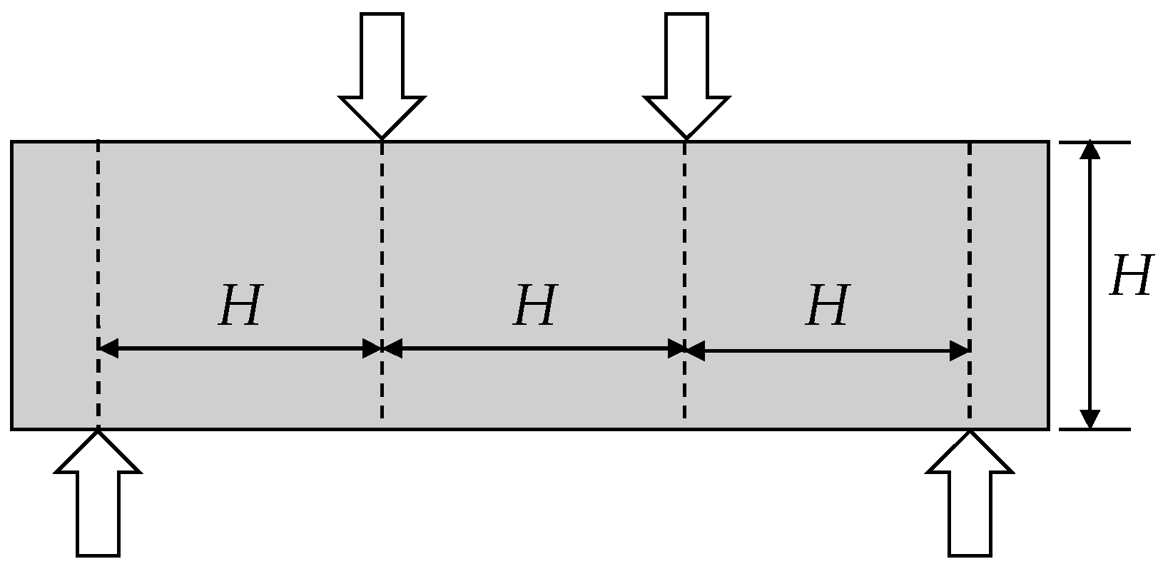
Figure 2.
Three-point loading method of EN 14651 [11].
Figure 2.
Three-point loading method of EN 14651 [11].
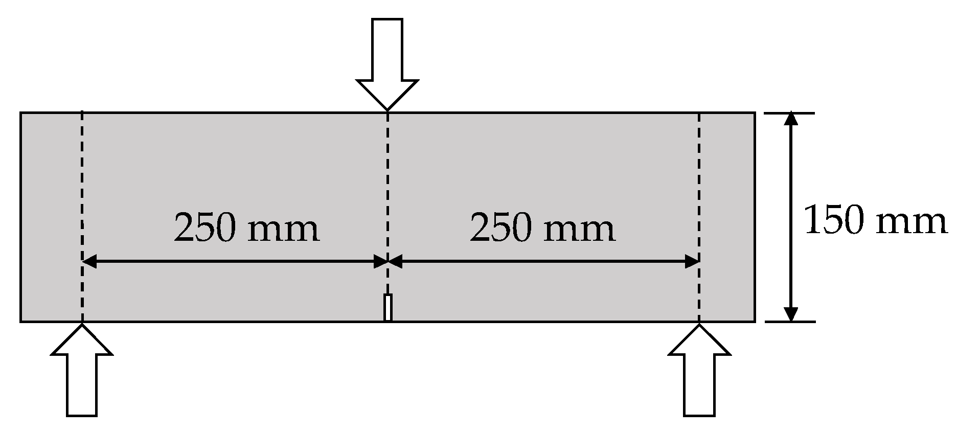
Figure 3.
Method of casting UHPC into molds for specimen preparation.
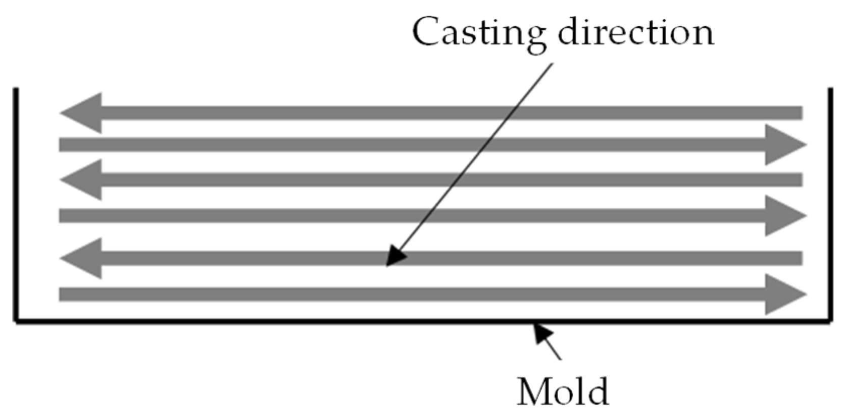
Figure 4.
Test set-up: (a) Three-point loading method; (b) Third-point loading method.
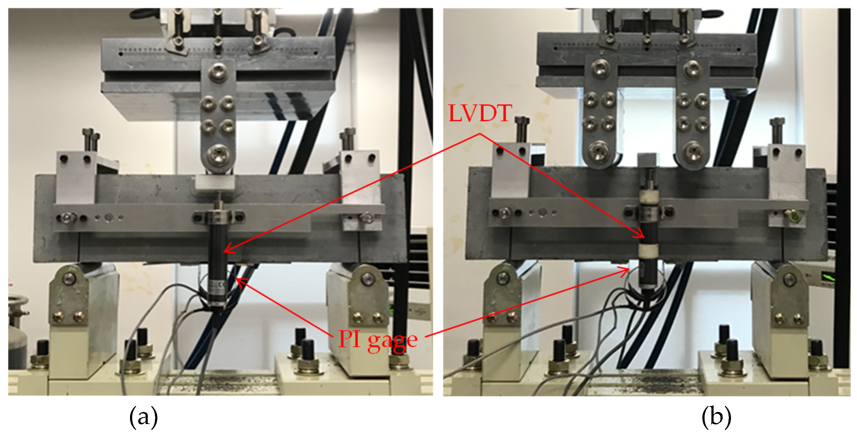
Figure 5.
Flexural tensile stress to deflection/span ratio relationship according to the presence of notch: (a) F13 specimens; (b) F19 specimens.
Figure 5.
Flexural tensile stress to deflection/span ratio relationship according to the presence of notch: (a) F13 specimens; (b) F19 specimens.
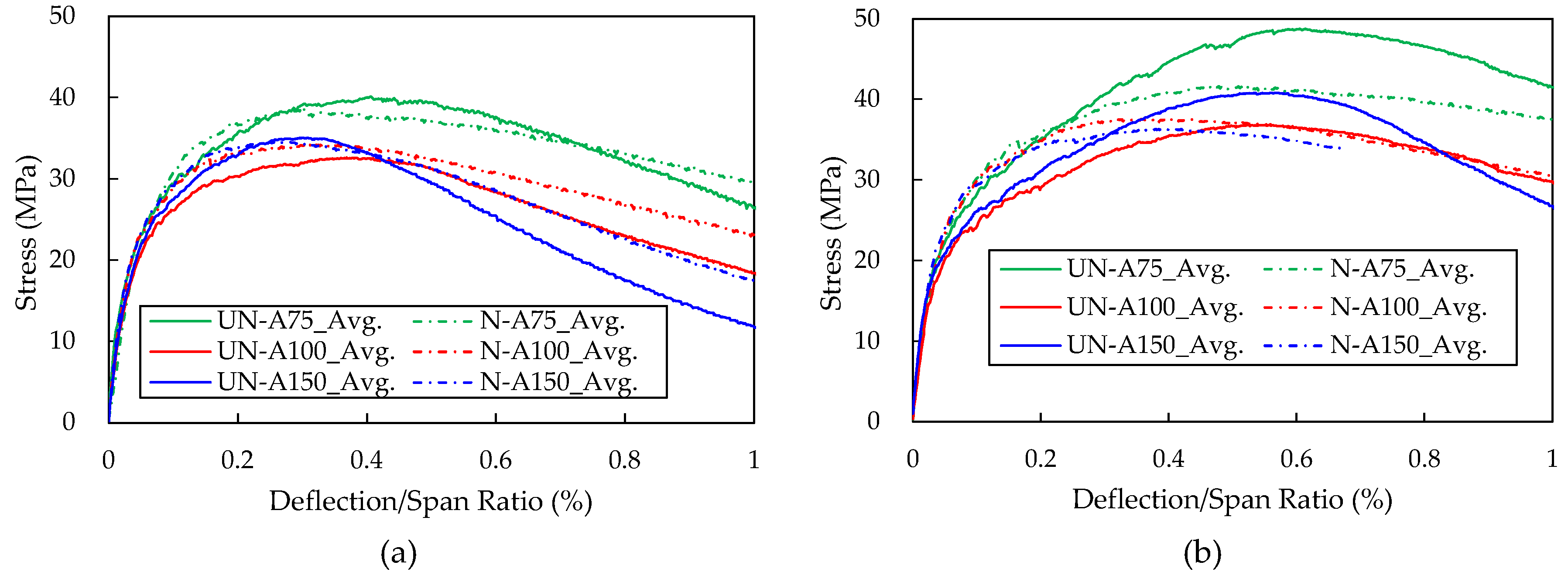
Figure 6.
Crack and failure patterns: (a) N-F19-4P-A75-#1 specimen; (b) UN-F19-4P-A75-#2 specimen; (c) UN-F19-4P-A150-#2 specimen.
Figure 6.
Crack and failure patterns: (a) N-F19-4P-A75-#1 specimen; (b) UN-F19-4P-A75-#2 specimen; (c) UN-F19-4P-A150-#2 specimen.
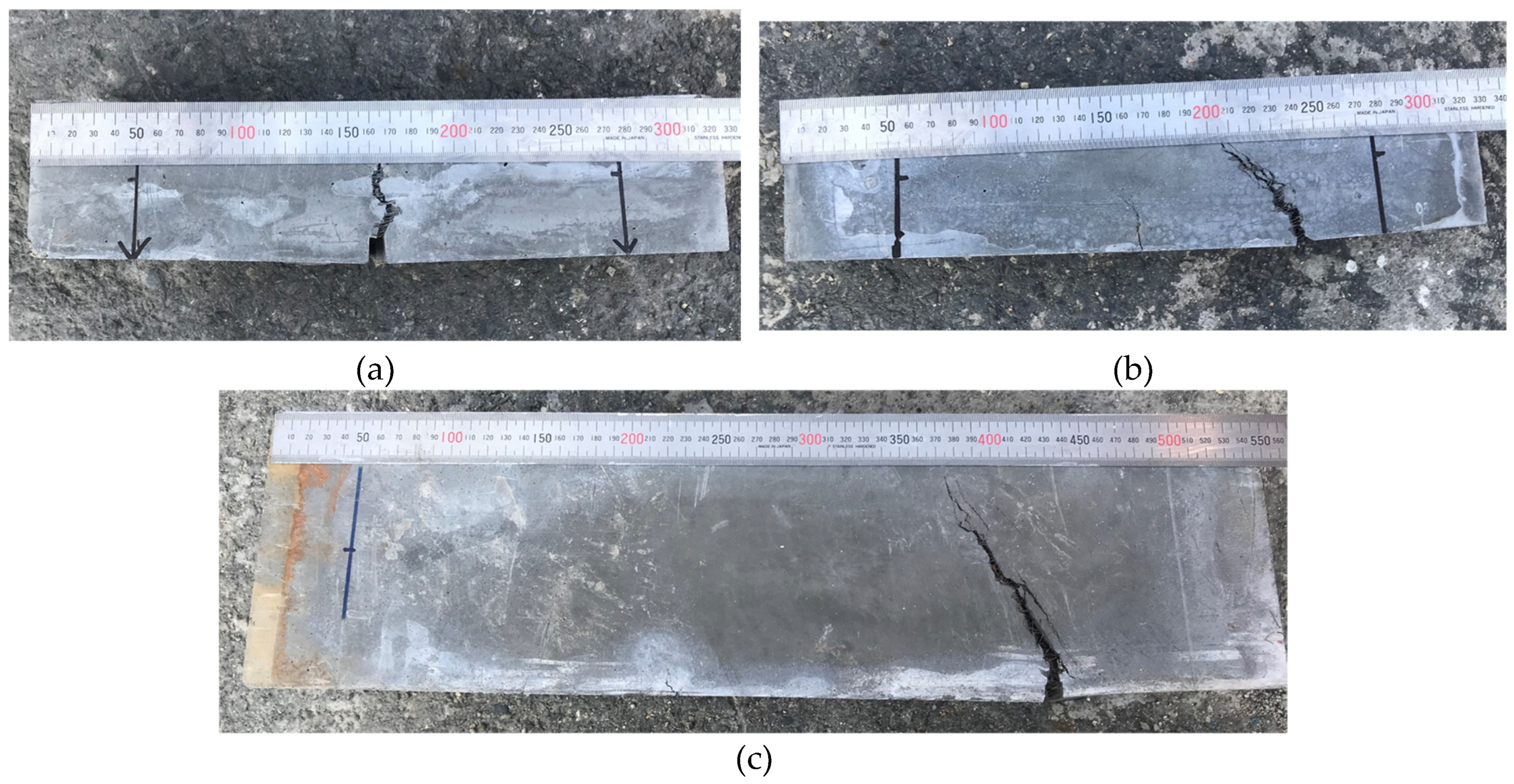
Figure 7.
Flexural tensile stress to CMOD/span ratio relationship according to the beam size: (a) N-F13-3P specimens; (b) N-F13-4P specimens; (c) N-F19-4P specimens.
Figure 7.
Flexural tensile stress to CMOD/span ratio relationship according to the beam size: (a) N-F13-3P specimens; (b) N-F13-4P specimens; (c) N-F19-4P specimens.
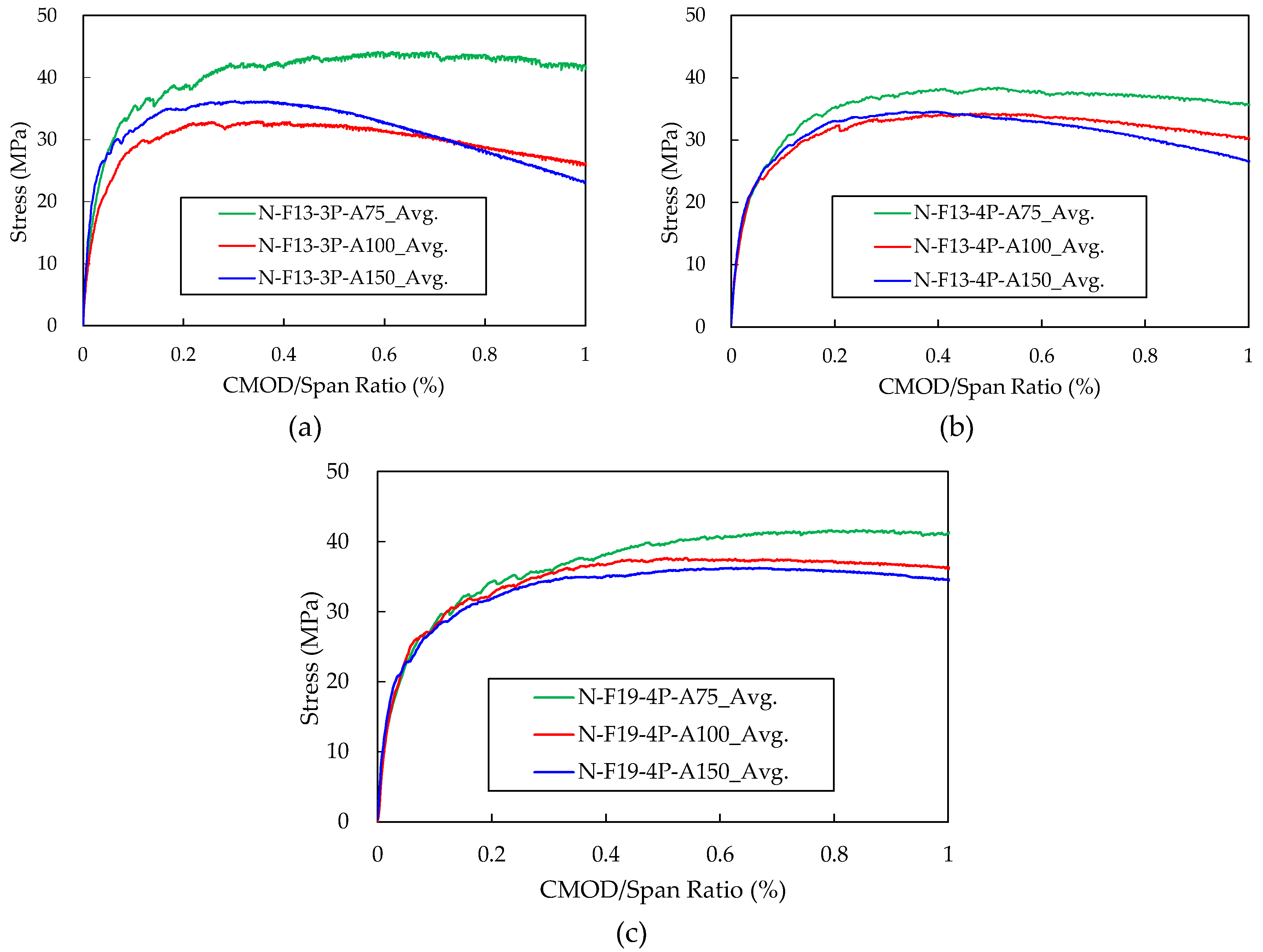
Figure 8.
Flexural tensile stress to deflection/span ratio relationship according to the loading method: (a) F13 specimens; (b) F19 specimens.
Figure 8.
Flexural tensile stress to deflection/span ratio relationship according to the loading method: (a) F13 specimens; (b) F19 specimens.
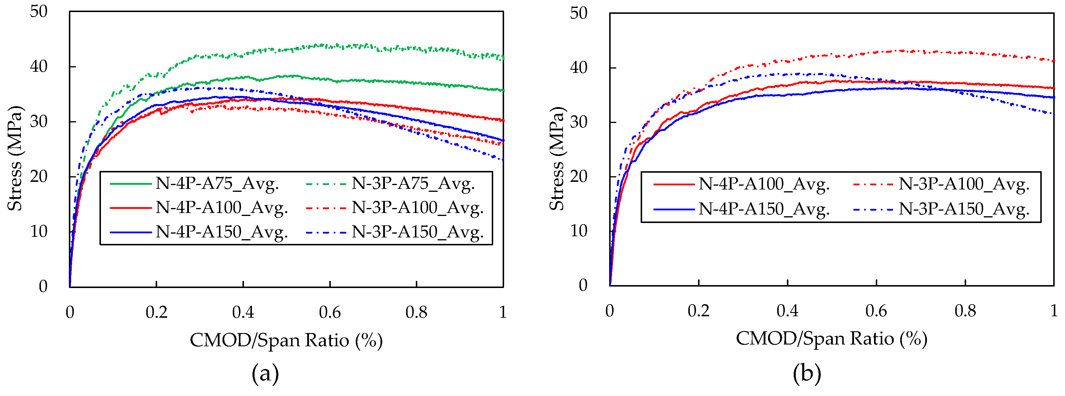
Figure 9.
Flexural tensile stress to CMOD/span ratio relationship according to the fiber length.
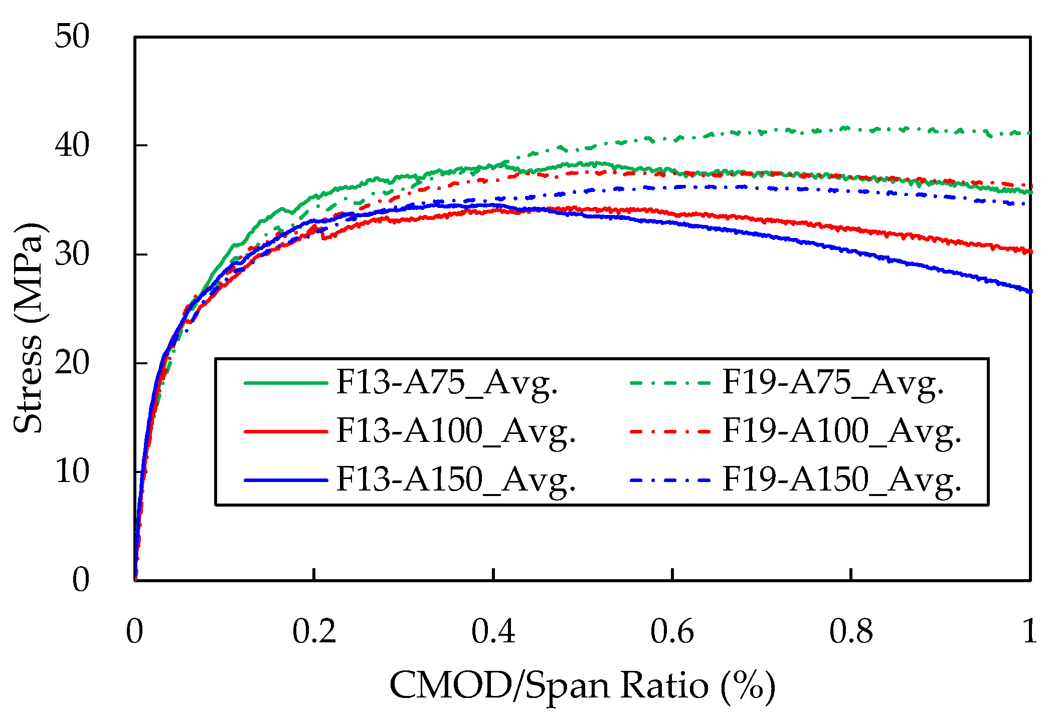
Table 1.
Load applying speed of ASTM C 1609 [10].
Table 1.
Load applying speed of ASTM C 1609 [10].
| Beam Size (mm) |
Span length, L (mm) |
L/900 (mm) |
Rate of increase in net deflection (mm/min) |
|
|---|---|---|---|---|
| Up to net deflection of L/900 | Beyond net deflection of L/900 | |||
| 100×100×350 | 300 | 0.33 | 0.025~0.075 | 0.05~0.20 |
| 150×150×500 | 450 | 0.50 | 0.035~0.100 | 0.05~0.30 |
Table 2.
Load applying speed of EN 14651 [11].
Table 2.
Load applying speed of EN 14651 [11].
| Beam Size (mm) |
Span length, L (mm) |
Rate of increase in CMOD (mm/min) | |
|---|---|---|---|
| Up to CMOD of 0.1 mm |
Beyond CMOD of 0.1 mm |
||
| 150×150×550 | 500 | 0.05 | 0.20 |
Table 3.
Test variables.
| Fiber length | 13.0 mm (F13) / 19.5 mm (F19) |
| Loading method | Third-point loading (4P) / three-point loading (3P) |
| Notch condition | Notched (N) / notched (UN) |
| Specimen cross-section geometry |
75 × 75 mm (A75) / 100 × 100 mm (A100) / 150 × 150 mm (A150) |
| [Note] Values in parentheses represent the variables shown in the specimen designation. | |
Table 4.
Specimen dimension according to fiber length in ASTM C 1856[9].
Table 4.
Specimen dimension according to fiber length in ASTM C 1856[9].
| Maximum fiber length (mm) | Specimen cross section |
|---|---|
| < 15 | 75 × 75 mm |
| 15 < < 20 | 100 × 100 mm |
| 20 < < 25 | 150 × 150 mm |
| 25 ≤ | 200 × 200 mm |
Table 5.
Notch size according to specimen size.
| Specimen cross section (mm) | Width of notch (mm) | Depth of notch (mm) |
|---|---|---|
| 75 × 75 mm | 5 | 12.5 |
| 100 × 100 mm | 5 | 16.7 |
| 150 × 150 mm | 5 | 25.0 |
Table 8.
Loading rate according to specimen size.
| Specimen cross section | Deflection criterion for changing the loading rate (mm) | Loading rate (mm/min) | |
|---|---|---|---|
| Up to the deflection criterion | Beyond the deflection criterion | ||
| 75 × 75 mm | 0.333 | 0.06 | 0.12 |
| 100 × 100 mm | 0.500 | 0.07 | 0.14 |
| 150 × 150 mm | 0.600 | 0.08 | 0.21 |
Table 9.
Average flexural tensile strength according to the presence of notch.
| Specimen | F13-4P | F19-4P | |||||||||||
|---|---|---|---|---|---|---|---|---|---|---|---|---|---|
| A75 | A100 | A150 | A75 | A100 | A150 | ||||||||
| UN | N | UN | N | UN | N | UN | N | UN | N | UN | N | ||
| Stress (MPa) |
@ deflection of L/600 | 33.55 (4.74) |
35.56 (0.69) |
29.70 (4.65) |
32.05 (1.08) |
31.80 (0.74) |
33.10 (1.04) |
32.94 (2.80)* |
33.87 (1.27) |
28.50 (0.30) |
33.74 (1.43) |
29.74 (0.60) |
33.06 (1.97) |
| @ deflection of L/150 | 35.90 (7.57) |
34.97 (0.90) |
26.48 (9.58) |
29.28 (2.38) |
22.53 (2.24) |
26.59 (2.58) |
48.34 (2.01) |
40.74 (1.83) |
35.92 (3.40) |
35.51 (2.17) |
39.43 (2.87) |
33.96 (2.35) |
|
| Max. | 41.23 (4.74) |
38.82 (0.79) |
33.95 (10.58) |
34.50 (2.69) |
35.61 (2.49) |
34.64 (1.71) |
49.50 (1.61) |
41.91 (2.15) |
36.99 (3.02) |
37.84 (1.84) |
41.19 (2.06) |
36.44 (2.15) |
|
| [Note] Values in parentheses indicate standard deviations. | |||||||||||||
Disclaimer/Publisher’s Note: The statements, opinions and data contained in all publications are solely those of the individual author(s) and contributor(s) and not of MDPI and/or the editor(s). MDPI and/or the editor(s) disclaim responsibility for any injury to people or property resulting from any ideas, methods, instructions or products referred to in the content. |
© 2025 by the authors. Licensee MDPI, Basel, Switzerland. This article is an open access article distributed under the terms and conditions of the Creative Commons Attribution (CC BY) license (http://creativecommons.org/licenses/by/4.0/).
Copyright: This open access article is published under a Creative Commons CC BY 4.0 license, which permit the free download, distribution, and reuse, provided that the author and preprint are cited in any reuse.


